CATALOG Welcome to the world of SmarAct.
|
|
|
- Buddy Lawrence
- 5 years ago
- Views:
Transcription
1 CATALOG 2017 Welcome to the world of SmarAct
2 TABLE OF CONTENTS INTRODUCTION... 3 LINEAR POSITIONERS...20 ROTARY POSITIONERS...54 GONIOMETERS...72 MICRO-GRIPPERS...82 OPTO-MECHANICS...92 PARALLEL KINEMATICS CONTROLLER AND SOFTWARE PICOSCALE
3 INTRODUCTION Welcome to the world of SmarAct
4 Copyright 2017 SmarAct GmbH Specifications are subject to change without notice. All rights reserved. Reproduction of images, tables or diagrams prohibited. The information given in this catalog was carefully checked by our team and is constantly updated. Nevertheless it is not possible to fully exclude the presence of errors. In order to always get the latest information, please contact our technical sales team. SmarAct GmbH, Schuette-Lanz-Straße 9, D Oldenburg Phone: +49 (0) , Telefax: +49 (0) Internet: 1
5 TABLE OF CONTENTS SMARACT - PERFECT MOTION...4 MISSION...4 EXPERIENCE...4 RESEARCH & DEVELOPMENT...4 UNIQUE PERFORMANCE...5 CUSTOMIZATION...5 INTRODUCTION...6 POSITIONING SYSTEMS...6 CONTROLLERS...7 POSITIONER PRODUCT RANGE...7 SERVICE...7 STICK-SLIP-PRINCIPLE...8 VACUUM COMPATIBILITY...9 SENSOR OPTIONS...10 OPTIONS...11 KEY FEATURE ICONS...12 TERMS AND DEFINITIONS
6 INTRODUCTION SMARACT - PERFECT MOTION Welcome to the world of SmarAct Mission SmarAct s mission is to supply high-quality positioning and position-measurement systems for high-precision applications down to the sub-nanometer-level. As freethinkers and with the ambition to be and stay technology leader in these fields we tackle daring requests with an open mind for new approaches and thus we often stun our customers with innovative solutions surpassing the requested performance. We love that our products and services help our customers in science and industry to achieve their goals in very different fields of technology and integration levels like in lab research, product development or OEM product integration. Experience SmarAct is located in Oldenburg (Germany) and was founded in As an independent, privately-owned company we have grown to a company with more than 100 employees. At SmarAct we cover not only the development of our product, but also the complete production process to ensure a high level of product quality and flexibility. We started with the development of piezo-based high-resolution positioning solutions for electron microscopes. Over the years we have broadened our portfolio with many new products like the unmatched parallel kinematics SmarPod and the miniaturized, high-performance interferometers PicoScale. We serve markets in research, photonics, microscopy as well as micro-assembly & automation - and more! Research & Development R&D forms the foundation of our success. With our experts in diverse fields as physics, material science, mechanical engineering, optics, electrical engineering and computer science we develop all parts of SmarAct products in-house, ranging from motor technology, controller, measurement technology to firmware and application software, leading to ever increasing performances of our products and thus strengthening our position as technology leader. In addition, our ap- 4
7 INTRODUCTION SMARACT - PERFECT MOTION Welcome to the world of SmarAct plication specialists are always ready to support you. Even if you are looking for a high-precision positioning or high-resolution measurement solution that is not available yet, please contact us - we may already be working on it. Unique Performance SmarAct systems are unique by their performance. SmarAct positioners are optimized for compactness and high stiffness and combine sub-nanometer-resolution motion with centimeter-travel ranges. The systems are robust and simple to use. With SmarAct s powerful controllers and software tools you can easily integrate nano-positioning systems into your setup. The PicoScale laser-interferometer is a powerful tool for displacement measurements with a picometer resolution. Moreover, it offers many on-board functions, like advanced universal signal processing in real-time. Customization Our experts from the sales team all have a technical background in fields as physics, material science, optics, or bio-material science and are looking forward to support you in finding the best solution for your positioning and/or measurement task. Here at SmarAct customization is a daily business. We have an unrivaled speed and flexibility in developing and building solutions as you need it - no matter whether it is a highly complex system or a recurrent, high-volume OEM system. I hope that this catalog is inspiring and I would be glad if SmarAct can be part of your next project. Axel Kortschack Managing Director HIGH QUALITY MADE IN GERMANY 5


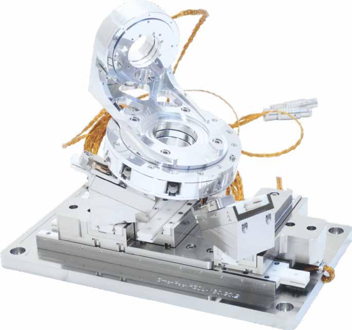
8 INTRODUCTION POSITIONING SYSTEMS Unique Features Extreme Miniaturization The SLC-1720-S with a size of 22 x 17 x 8.5 mm³ is the world s smallest closed-loop nano positioner with macroscopic travel. All-Inclusive Positioner Each positioner consists of a high quality guideway, a SmarAct drive and an optional high-resolution sensor. Optimized Straight Motion SmarAct drives are optimized to translate the maximum of the power into motion along the direction of the guideway. Wobbling and lateral motion are kept at a minimum required for real nanopositioning. Backlash-Free Since the movable part of the positioner is permanently connected to the drive by a friction contact there is no backlash. Self-Clamping Even with switched-off controllers, SmarAct drives keep their position. Vacuum Compatibility All positioning systems can be prepared for vacuum applications down to mbar. Robust Design Moving to mechanical endstops, obstacles or moving the slide of the positioner by hand does not damage the positioner. Versatility All positioners can be applied in any orientation. High Resolution and Accuracy SmarAct standard positioners provide about 1nm closed-loop positioning resolution and some tens of nanometer repeatability - over the whole travel range. High Dynamic Velocity Range The velocity of the positioners range from nm/s to several cm/s. Cost-Effective You are able to create very cost-effective solutions based on SmarAct s positioning systems and expertise. Future-Proof / Modular Consequent modularity and various options for the manipulators and controllers allow to build custom-specific solutions and ensure upgradability. Low Thermal Drift, High Resonance Frequencies Due to the high level of miniaturization, a sophisticated design, an optimized material combination as well as optimized control modes, low thermal drift and high resonance frequencies are achieved. Large Travel Range with Nanometer Resolution SmarAct standard positioners provide centimeter travel ranges - with sub-nanometer resolution of motion. Compact 3D Manipulator based on SLC-1720-S world s smallest closed-loop positioner with macroscopic travel 6


9 INTRODUCTION POSITIONING SYSTEMS Unique Features Controllers Plug-and-Position The micro- and nanopositioning systems are ready-to-use. Once you connect the motion system to the controller and power it up, you are ready for high-end micro- and nanopositioning. Compact Controllers SmarAct controllers are compact, even if equipped with many channels. Furthermore, all of SmarAct s controllers are available with table-top housings as well as very compact single board solutions for OEM customers and 19 rack mounted multi-channel control systems. MCS2 SmarAct s flagship controller Positioner Product Range Our product range includes several positioner lines, covering most micro- and nanopositioning tasks. SLC Series The SLC-Series covers linear positioners with crossed-roller slides, including the SLC-17 and SLC-24 lines. SL Series The SL-Series covers linear positioners with ball slides, including the ultra-compact SL-06 positioner. SLS Series The robust positioners of the SLS series can be easily combined. SHL Series Based on the SLC series, the SHL is designed for heavy loads up to a few kg. SR Series The SR-Series covers all rotary positioners. SGO Series The SGO-Series covers high-precision goniometers with crossed-roller slides. SmarPod Series Based on our positioners we offer a series of high precision parallel kinematic systems with 6 degrees of freedom and for a wide range of applications. Opto-Mechanics Opto-mechanic motion systems such as motorized filter wheels, motorized mirror mounts, optical slits and motorized iris diaphragms are available within SmarAct s product range. Service Complete Systems Based on our positioners we offer simple and complex kinematics, such as microassembling stations, microscope stages, fiber alignment systems and many more. Every systems can be tailored to your requirements. Customization Positioners, manipulators and controllers can be customized to non-standard requirements. If you need a positioner with a certain travel range, size or guideway or if you need a special controller, please contact us and we will find a solution. Complete Application Development On demand SmarAct supports the development of complete applications, based on customer specifications. This includes mechanics, electronics as well as application processes. 7
10 INTRODUCTION STICK-SLIP-PRINCIPLE High-Precision Piezoelectric Motors All positioners from SmarAct are available with a patented Stick-Slip drive, enabling macroscopic travel with high velocities. With this technique our positioners can move with sub-nanometer resolution. The basic principle is explained below. SLIDE PIEZO VOLTAGE TIME I: A piezo actuator is attached to the slide of the guideway by a friction element. The piezo actuator itself is fixed at the stationary base of the positioner. STICK SLOW VOLTAGE TIME II: The piezo actuator is changing its length proportional to the applied voltage. As long as the friction element is not accelerated too fast, the slide will follow the movement of the friction element and thus experiencing the same acceleration. This phase is called stick-phase. SLIP FAST VOLTAGE TIME III: The friction element is accelerated very fast. The inertial force of the accelerated mass of the slide is higher than the friction force. The friction element slips over the surface of the slide. As a result, the friction element is changing its position, while the slide stays in its position. This phase is called slip-phase. By repeating that sequence macroscopic travel of the slide can be achieved. This mode is called step mode. STICK SLOW VOLTAGE TIME IV: During the stick-phase the slide can be moved by slowly elongating the piezo actuator with subnanometer resolution. This mode is called scan mode. 8
 or ultra-high vacuum (UHV, down to 10-11 mbar) environment.")

 Ultra-High Vacuum (UHV) Ultra-High Vacuum (UHVT) Pressure down to 10-6 mbar down to 10-11 mbar Wiring Teflon - insulated stranded wires with braided shield and")
11 INTRODUCTION VACUUM COMPATIBILITY High-Precision Positioning at Vacuum Conditions SmarAct positioners are not only designed for normal ambient conditions. Most of our positioners can be prepared to work in a high vacuum (HV, down to 10-6 mbar) or ultra-high vacuum (UHV, down to mbar) environment. We deliver complete systems containing the feedthroughs, plugs and complete cabling. Different flange sizes and feedthroughs are available upon request. Vacuum Feedthrough with Sensor Module directly mounted onto the matching connectors of a flange. UHV Feedthrough Welded into a DN40CF Flange with three multipin feedthroughs and Kapton insulated wires. Standard Atmosphere High Vacuum (HV) Ultra-High Vacuum (UHV) Ultra-High Vacuum (UHVT) Pressure down to 10-6 mbar down to mbar Wiring Teflon - insulated stranded wires with braided shield and Teflon coating Teflon - insulated stranded wires with braided shield Kapton - insulated insulated stranded wires Teflon - insulated stranded wires with braided shield Grease standard grease HV compatible grease grease-free, ceramic-coated guideways Sensor Options -I, -M, -L, -S -I, -S -S T Bake-Out upon request 130 C recommended 130 C (max. 150 C) Vacuum Feedthrough SCU, MCS LEMO feedthroughs O-ring tightened by a screw nut flanges available upon request electronics outside the vacuum chamber metal or ceramic multipin as well as PEEK D-SUB15 feedthrough welded into a flange multipin feedthrough with brass, nickel, chrome, stainless steel DN40CF or DN63CF flange, other sizes upon request electronics outside the vacuum chamber 9
12 INTRODUCTION SENSOR OPTIONS High-Precision Closed-Loop Positioning If your application requires closed-loop positioning, optical encoders can be integrated into our positioners for feedback. With integrated sensors you can perform closed-loop operations such as defining the desired travel distance, the target position or the speed. We are offering different types of position measurement sensors. These sensors are available for microscopic resolutions (-I, -M) and nanoscopic resolutions (-L, -S, -SC) down to sub nanoscopic resolutions (PicoScale). Integrating -I, -M, -L, -S and -SC sensors into our positioners has no effect on their outer dimensions. Nanosensor Options Our optical linear -S/-SC nanosensor has a resolution of about 1 nm and an absolute accuracy of 1 μm/m. The rotary counterpart has a resolution of about 10 μ, depending on the diameter of the rotary positioner. Positioners with an integrated -S/-SC sensor must be connected to an MCS/MCS2 or SDC/SDC2 control system. The controller can then use the sensor values for closed-loop position control. The optical linear -L sensor, which can be connected to all SCU, MCS and SDC/SDC2 controllers, offers a resolution of 4 nm (depending on the controller). Microsensor Options Alternatively, most of the SmarAct positioners can be equipped with -M or -I sensor. These sensor types have a resolution of about 0.1 μm for the optical version, 0.3 μm for the inductive version and an absolute accuracy of about 10 μm/m (optical) or 25 μm/m (inductive). The optical rotary sensor has a resolution of about 10 m. Positioners with an integrated, optical microsensor can be connected to an HCU-3CM, CU-3CM, MCS or SDC/SDC2 controller, for closedloop position control. Our inductive microsensor can be controlled with one of our EMS controllers. Order Codes To order a positioner with integrated sensor please add -M, -I, -S, -SC or -L to the order code of the positioner (e.g. SLC-1730-S, SLC-1730-M, SLC I). -M -I -L -S/ -SC Principle optical inductive optical optical Resolution down to 100 nm 300 nm 4 nm 1 nm Repeatability down to 1 μm down to 2.5 μm down to 50 nm (depending on travel distance) down to 20 nm (depending on travel distance) Absolute Accuracy 10 μm/m 25 μm/m 5 μm/m 1 μm/m Reference Position endstop Controller SCU, MCS /MCS2 EMS 2D/3D, SCU endstop or multiple reference marks SCU, MCS /MCS2, SDC/SDC2 single (-S), multiple (-SC) reference marks MCS /MCS2, SDC/SDC2 Vacuum Compatibility atmospheric pressure only down to 10-6 mbar atmospheric pressure only down to mbar Smallest Positioner SLC-1730-M / SR-4011-M SLC-1730-I/ SR-4513-I SLC-1720-L / SR-4011-L SLC-1720-S / SR-2013-S 10
13 INTRODUCTION OPTIONS Individually Tailored High Precision Positioning Non-Magnetic Materials Many of our positioners, especially the SLC- and SR-series, are also available in a complete non-magnetic version, including the necessary guideways. Typical materials are copper beryllium, titanium, ceramics and copper wires insulated with Teflon or Kapton. In most cases the dimensions remain unchanged and it is possible to integrate a micro- or nanosensor. Coated ceramics can also be used upon request. Please add -NM to the order code for the non-magnetic version of the positioner or ask us for available customization. Higher Blocking Force and Constant Force Springs The blocking force is the maximum force that a positioner can apply to another object. For certain applications the blocking force required is higher than specified for our standard positioners. In this case the blocking force can be increased without changing the positioner s outer dimensions. To order positioners with increased blocking force please add -D to the order code of the positioner, e.g. SLC-2445-D. If high constant loads shall be lifted a constant force spring can be integrated to counterbalance the high load. In some cases this does not even change the outer dimensions of the positioner or positioning system. Guideways for Extended Lifetime Positioners of the SLC-series and SGO-series are also available with an extended lifetime of the positioner compared to the standard version. The dimensions of the positioners remain unchanged and it is completely compatible with a micro- or a nanosensor. To order this option, please add -Z to the order codes. Low-Vibration Mode For ultra-high precision applications SmarAct offers a patented special low-vibration mode for our MCS control systems. This mode reduces vibrations, which occur due to the stick-slip driving principle. The resulting smooth motion enables the use of our standard positioners for demanding applications, like AFM measurements and biological experiments. To order our control systems with the low vibration mode, the option -LV can be added to the MCS control systems. Advanced Sensor Calibration SmarAct s unique advanced sensor calibration algorithm allows to increase the overall absolute accuracy of all our nano encoded positioners by compensating variations in the position sensors without the need of an external mapping device. This means our positioners can be used for applications with highest demands in absolute accuracy. Customized Materials SmarAct offers different materials for the base plates, guideways or connection elements. With our high expertise in fine mechanics we are capable to handle many different materials. Typical materials are aluminum, titanium and stainless steel. Please feel free to contact us to learn more about the various options. 11
14 INTRODUCTION KEY FEATURE ICONS Main Features at a Glance SmarAct positioners are not only designed for normal ambient conditions. Most of our positioners can be prepared to work in a high vacuum (HV, down to 10-6 mbar) or ultra-high vacuum (UHV, down to mbar) environment. We deliver complete systems containing the feedthroughs, plugs and complete cabling. Different flange sizes and feedthroughs are available upon request. Minimum movement resolution Aperture of the motorized iris diaphragm resolution aperture Linear travel range Control mode (open-loop, closed-loop) travel range control rotation Rotation of the rotary positioner, tilting of the goniometer or optical mount control channels Number of available control channels for the specific control unit center of rotation Center of rotation of the goniometer sensor type Sensor types, which can be controlled with the given control unit Size of the positioner size N Maximum normal load normal load gripping force Maximum gripping force Vacuum compatibility vacuum non magnetic Non-magnetic materials available 12
15 13


16 INTRODUCTION TERMS AND DEFINITIONS What needs to be considered... Movement Resolution The resolution of movement is the smallest position increment that can be effectively achieved with the positioner. Closed-Loop Resolution Closed-loop positioning resolution is the smallest executable position increment when positioning with sensor feedback. Repeatability The repeatability (bidirectional) is the accuracy, the position can be approached again within the movement range of the positioner after any position change. Since the positioning goal is given with respect to the sensor system the repeatability is in the same order of magnitude as the closed-loop positioning resolution. Please note that the repeatability also depends on the thermal and mechanical conditions. Accuracy The absolute accuracy of a position sensor is the maximum difference between the target position and achieved position. This difference is caused by nonli- near behaviour of the actuator and sensor scale and by the alignment error of the sensor scale in relation to the axis of movement. The absolute accuracy also depends on the thermal and mechanical conditions. Angular Deviations Due to the imperfectness of the guideway a movement along the travel causes a deviation from the pure linear movement in roll (Q R ) pitch (Q P ) and yaw (Q Y ) Max. Load and Torque F N is the maximum force that can be applied perpendicularly to the center of the slide without damaging it. Please note that for an accurate and smooth rolling the maximum load should not exceed 2 kg (higher loads on request). F B is the blocking force of a linear positioner, wich is the maximum force an actuator can generate if infinitely rigid restrained. F L is the maximum weight which can be applied to a vertical orientated positioner. M P, M Y and M R are the maximum torques which can be applied to the positioner without damaging it. 14


17 INTRODUCTION TERMS AND DEFINITIONS What needs to be considered... Wobble Similar to the angular deviations for a linear movement, wobble is the tilt of the axis of rotation relative to the ideal axis. It results in a cyclic tilting of the rotating surface during each revolution. Eccentricity Eccentricity is the radial (perpendicular to the axis of rotation) deviation of the center of rotation from its mean position after rotating through one full revolution. It is also known as radial runout. A perfectly centered stage with perfect bearings would have no eccentricity. Max. Load and Torque M B is the maximum (blocking) torque the rotation stage can generate. M R /F R is the maximum torque/force one can apply perpendicular to the rotation axis of the positioner without damaging it. F N is the maximum nominal force the positioner can tolerate. 15
18 16
19 About SmarAct SmarAct develops high-performance solutions for handling and positioning in the micro- and nanometer range. The broad product portfolio - from single positioners to complex parallel kinematics, miniaturized robots and easy-to-use control systems - is completed by sophisticated measuring equipment based on powerful laser interferometers. We serve high accuracy positioning and metrology applications in research and industry within such fields as optics, life sciences, micro-assembly, semiconductors and microscopy. Maintaining the complete production in house allows a high level of customization so that we can always provide you the optimal individual or OEM solution. HEADQUARTERS SmarAct GmbH Schuette-Lanz-Strasse Oldenburg Germany T: info-de@smaract.com USA SmarAct Inc Shattuck Ave., Suite 1103 Berkeley, CA United States of America T: info-us@smaract.com 07/2017

20 LINEAR POSITIONERS Piezo-based high-performance linear micro- and nanopositioners
21 Copyright 2017 SmarAct GmbH Specifications are subject to change without notice. All rights reserved. Reproduction of images, tables or diagrams prohibited. The information given in this catalog was carefully checked by our team and is constantly updated. Nevertheless it is not possible to fully exclude the presence of errors. In order to always get the latest information, please contact our technical sales team. SmarAct GmbH, Schuette-Lanz-Straße 9, D Oldenburg Phone: +49 (0) , Telefax: +49 (0) Internet: 1
22
23 TABLE OF CONTENTS ABOUT LINEAR POSITIONERS...4 SLC-17 SERIES...5 SLC SLC SLC SLC SLC SLC SLC SLC-24 SERIES...14 SLC SLC SLC SLC SLC SLC SLC SLC SLC SL SERIES...24 SL SL-06xx...25 SLL SERIES...26 SLL ACCESSORIES...26 SLL SLLA SLLV SHL SERIES...30 SHL 20N
24 LINEAR POSITIONERS ABOUT LINEAR POSITIONERS Nanometer Precision Linear Positioners Based on our patented piezo driving technology, we are offering several lines of linear positioners. Some of those positioners are shown in the following section. Positioners from the SLC series are based on linear slides with ball or crossed-roller bearings and are characterized by their high rigidity and straightness. They should be chosen for compact nanopositioning systems with or without sensor feedback. Based on the SLC series, the SHL line for heavy loads is available. Positioners from the SLL series are based on ball or crossed-roller bearings. The small slide in combination with a long rail makes it an interesting solution for long range positioning within limited space and a cost effective micro- and nanopositioning system. Positioners from the SL series are ultra-compact and based on slides with linear ball bearings. They are well-suited for micro-positioning systems, where space is the top priority. Product Line SLC SL SLL SHL Positioner Series SLC-17 SLC-24 SL-06 SLL12 SLL(A/V)42 SHL-20N-10 Mechanical Open-Loop blocking force [N] max. normal force [N] max. lift force [N] 1.5, 2.2 (-D) 1.5, 2.2 (-D) cross section [mm 2 ] 17 x x x x x x 50 length [mm] weight [g] pitch torque [Nm] yaw torque [Nm] roll torque [Nm] travel [mm] step width [nm] piezo scan range [µm] > 1.5 > > 1.5 > scan resolution [nm] < 1 < 1 < 1 < 1 < 1 < 1 velocity [mm/s] > 20 > 20 > 13 > 20 > 20 > 9 Closed-Loop max. frequency [khz] sensor resolution [nm] cl resolution [nm] 1 (-S, -SC), 4 (-L), 100 (-M) 1 (-S, -SC), 4 (-L), 100 (-M) 1 (-S, -SC) 100 (-M) 1 (-S, -SC) 100 (-M) 1 (-S, -SC), 4 (-L), 100 (-M) repeatability, full stroke [nm] ± 25.. ± 80 ± 30.. ± 180 ± 70.. ± 450 ± 70.. ± 450 ± 100 no sensor sensor types -M, -S, -SC, -I, -L -M, -S, -SC, -I, -L -M, -S, -SC -M, -S, -SC -M, -S, -SC, -L available vacuum compatibility HV, UHV HV, UHV HV, UHV HV HV HV, UHV 4


25 LINEAR POSITIONERS SLC-17 SERIES Nanometer Precision Linear Positioner The positioners in the SLC-17 series are 17 mm wide and 8.5 mm high each. They are very rigid and therefore ideally suited for micro- and nanopositioning systems where stability and high accuracy have first priority. Despite their small size, a position sensor for micro- and nanopositioning tasks can be optionally integrated into each positioner without affecting the positioner s outer dimensions. Due to this high integration the SLC-1720-S is the smallest available closed-loop nanopositioner with macroscopic travel range. 5

26 LINEAR POSITIONERS SLC-1720 Nanometer Precision Linear Positioner resolution travel range N normal load non magnetic vacuum size < 1 nm 12 mm 20 N (2 kg) available down to mbar 22 x 17 x 8.5 mm 3 Mechanical Properties blocking force F B max. normal force F N max. lift force F L > 3.5 N 20 N > 1.5 N positioner dimension 22 x 17 x 8.5 mm 3 weight 13 g pitch torque M P 0.6 Nm yaw torque M Y 0.6 Nm roll torque M R 0.4 Nm Positioning travel ± 6 (12) mm step width 1-1,500 nm* scan range > 1.5 μm scan resolution < 1 nm velocity > 20 mm/s max. frequency 18.5 khz Materials and Vacuum Options*** steel base (-ST), titanium base (-TI) non magnetic materials (-NM****) black anodized (-BK) external support for increased M Y, M R (-W) high precision bearing (-P) increased blocking force (-D, +1.5 N) -HV (10-6 mbar), -UHV / -UHVT (10-11 mbar) Closed-Loop with -S sensor resolution 1 nm repeatability ± 25 nm** Closed-Loop with -L*** sensor resolution 4 nm closed loop resolution ± 500 nm (H)CU 4 nm MCS repeatability ± 1 μm (H)CU ± 50 nm MCS x M2 x x M2 x n2h7 x n2h7 x x M1.6 x Open-Loop x M1.6 x S Closed-Loop Linear dimensions are given in mm. 6 * for low-vibration mode (-LV), for scan-mode < 1 nm, otherwise 50-1,500 nm ** measured over the complete travel range, for shorter travel much better *** with mechanical end stops, 3 mm reduced travel **** positioner dimensions, mounting holes and travel range may vary and can be customized ***** all holes M1.6, no dowel holes, screwing depth: min. 3 mm, max. 3.5 mm

27 LINEAR POSITIONERS resolution travel range N normal load non magnetic vacuum size SLC-1730 Nanometer Precision Linear Positioner < 1 nm 21 mm 30 N (2 kg) available down to mbar 30 x 17 x 8.5 mm 3 Mechanical Properties blocking force F B max. normal force F N max. lift force F L > 3.5 N 30 N > 1.5 N positioner dimension 30 x 17 x 8.5 mm 3 weight pitch torque M P yaw torque M Y roll torque M R 20 g 1.2 Nm 1.2 Nm 0.6 Nm Positioning travel ± 10.5 (21) mm step width 1-1,500 nm* scan range > 1.5 μm scan resolution < 1 nm velocity > 20 mm/s max. frequency 18.5 khz Materials and Vacuum Options**** steel base (-ST), titanium base (-TI) non magnetic materials (-NM*****) black anodized (-BK) external support for increased M Y, M R (-W) high precision bearing (-P) increased blocking force (-D, +1.5 N) integrated connecting elements (-O) Closed-Loop with -S sensor resolution 1 nm repeatability ± 30 nm** Closed-Loop with -L*** sensor resolution 4 nm closed loop resolution ± 500 nm (H)CU 4 nm MCS repeatability sensor resolution closed loop resolution repeatability ± 1 μm (H)CU ± 60 nm MCS Closed-Loop with -M*** 100 nm ± 500 nm (H)CU 100 nm MCS ± 2.5 μm (H)CU ± 0.5 µm MCS x M2 x n2h7 x x M1.6 x 3.5 Linear dimensions are given in mm. 7 * for low-vibration mode (-LV), for scan-mode < 1 nm, otherwise 50-1,500 nm ** measured over the complete travel range, for shorter travel much better *** with mechanical end stops, 3 mm reduced travel **** positioner dimensions, mounting holes and travel range may vary and can be customized ***** all holes M1.6, no dowel holes, screwing depth: min. 3 mm, max. 3.5 mm

28 LINEAR POSITIONERS SLC-1740 Nanometer Precision Linear Positioner resolution travel range N normal load non magnetic vacuum size < 1 nm 26 mm 30 N (3 kg) available down to mbar 40 x 17 x 8.5 mm 3 Mechanical Properties blocking force F B max. normal force F N max. lift force F L > 3.5 N 30 N > 1.5 N positioner dimension 40 x 17 x 8.5 mm 3 weight pitch torque M P yaw torque M Y roll torque M R 26 g 3.0 Nm 3.0 Nm 1.0 Nm Positioning travel ± 13 (26) mm step width 1-1,500 nm* Closed-Loop with -S scan range > 1.5 μm sensor resolution 1 nm scan resolution < 1 nm repeatability ± 40 nm** velocity > 20 mm/s Closed-Loop with -L*** max. frequency 18.5 khz sensor resolution 4 nm Materials and Vacuum Options**** steel base (-ST), titanium base (-TI) non magnetic materials (-NM*****) closed loop resolution repeatability ± 500 nm (H)CU 4 nm MCS ± 1 μm (H)CU ± 80 nm MCS black anodized (-BK) integrated connecting elements (-O) sensor resolution Closed-Loop with -M*** 100 nm external support for increased M Y, M R (-W) high precision bearing (-P) increased blocking force (-D, +1.5 N) -HV (10-6 mbar), -UHV / -UHVT (10-11 mbar) closed loop resolution repeatability 500 nm (H)CU 100 nm MCS ± 2.5 μm (H)CU ± 0.5 µm MCS x M2 x n2h7 x x M1.6 x 3.5 Linear dimensions are given in mm. 8 * for low-vibration mode (-LV), for scan-mode < 1 nm, otherwise 50-1,500 nm ** measured over the complete travel range, for shorter travel much better *** with mechanical end stops, 3 mm reduced travel **** positioner dimensions, mounting holes and travel range may vary and can be customized ***** all holes M1.6, no dowel holes, screwing depth: min. 3 mm, max. 3.5 mm
29 LINEAR POSITIONERS resolution travel range N normal load non magnetic vacuum size SLC-1750 Nanometer Precision Linear Positioner < 1 nm 31 mm 30 N (3 kg) available down to mbar 40 x 17 x 8.5 mm 3 Mechanical Properties blocking force F B max. normal force F N max. lift force F L > 3.5 N 30 N > 1.5 N positioner dimension 50 x 17 x 8.5 mm 3 weight pitch torque M P yaw torque M Y roll torque M R 32 g 4.6 Nm 4.6 Nm 1.2 Nm Positioning travel ± 15.5 (31) mm step width 1-1,500 nm* scan range > 1.5 μm scan resolution < 1 nm velocity > 20 mm/s max. frequency 18.5 khz Materials and Vacuum Options**** steel base (-ST), titanium base (-TI) non magnetic materials (-NM*****) black anodized (-BK) integrated connecting elements (-O) external support for increased M Y, M R (-W) high precision bearing (-P) increased blocking force (-D, +1.5 N) Closed-Loop with -S sensor resolution 1 nm repeatability ± 50 nm** Closed-Loop with -L*** sensor resolution 4 nm closed loop resolution ± 500 nm (H)CU 4 nm MCS repeatability sensor resolution closed loop resolution repeatability ± 1 μm (H)CU ± 100 nm MCS Closed-Loop with -M*** 100 nm 500 nm (H)CU 100 nm MCS ± 2.5 μm (H)CU ± 0.5 µm MCS -HV (10-6 mbar), -UHV / -UHVT (10-11 mbar) x M2 x n2h7 x x M1.6 x 3.5 Linear dimensions are given in mm. 9 * for low-vibration mode (-LV), for scan-mode < 1 nm, otherwise 50-1,500 nm ** measured over the complete travel range, for shorter travel much better *** with mechanical end stops, 3 mm reduced travel **** positioner dimensions, mounting holes and travel range may vary and can be customized ***** all holes M1.6, no dowel holes, screwing depth: min. 3 mm, max. 3.5 mm
30 LINEAR POSITIONERS SLC-1760 Nanometer Precision Linear Positioner resolution travel range N normal load non magnetic vacuum size < 1 nm 41 mm 30 N (3 kg) available down to mbar 60 x 17 x 8.5 mm 3 Mechanical Properties blocking force F B max. normal force F N max. lift force F L > 3.5 N 30 N > 1.5 N positioner dimension 60 x 17 x 8.5 mm 3 weight pitch torque M P yaw torque M Y roll torque M R 38 g 7.6 Nm 7.6 Nm 1.4 Nm Positioning travel ± (41) mm step width 1-1,500 nm* Closed-Loop with -S scan range > 1.5 μm sensor resolution 1 nm scan resolution < 1 nm repeatability ± 60 nm** velocity > 20 mm/s Closed-Loop with -L*** max. frequency 18.5 k Hz sensor resolution 4 nm Materials and Vacuum Options**** steel base (-ST), titanium base (-TI) non magnetic materials (-NM*****) black anodized (-BK) closed loop resolution repeatability ± 500 nm (H)CU 4 nm MCS ± 1 μm (H)CU ± 120 nm MCS Closed-Loop with -M*** integrated connecting elements (-O) external support for increased M Y, M R (-W) high precision bearing (-P) increased blocking force (-D, +1.5 N) -HV (10-6 mbar), -UHV / -UHVT (10-11 mbar) sensor resolution closed loop resolution repeatability 100 nm 500 nm (H)CU 100 nm MCS ± 2.5 μm (H)CU ± 0.5 µm MCS x M2 x n2h7 x x M1.6 x 3.5 Linear dimensions are given in mm. 10 * for low-vibration mode (-LV), for scan-mode < 1 nm, otherwise 50-1,500 nm ** measured over the complete travel range, for shorter travel much better *** with mechanical end stops, 3 mm reduced travel **** positioner dimensions, mounting holes and travel range may vary and can be customized ***** all holes M1.6, no dowel holes, screwing depth: min. 3 mm, max. 3.5 mm
31 LINEAR POSITIONERS resolution travel range N normal load non magnetic vacuum size SLC-1770 Nanometer Precision Linear Positioner < 1 nm 46 mm 30 N (3 kg) available down to mbar 70 x 17 x 8.5 mm 3 Mechanical Properties blocking force F B max. normal force F N max. lift force F L > 3.5 N 30 N > 1.5 N positioner dimension 70 x 17 x 8.5 mm 3 weight pitch torque M P yaw torque M Y roll torque M R 45 g 10.1 Nm 10.1 Nm 1.6 Nm Positioning travel ± 23 (46) mm step width 1-1,500 nm* scan range > 1.5 μm scan resolution < 1 nm velocity > 20 mm/s max. frequency 18.5 k Hz Materials and Vacuum Options**** steel base (-ST), titanium base (-TI) non magnetic materials (-NM*****) black anodized (-BK) integrated connecting elements (-O) external support for increased M Y, M R (-W) high precision bearing (-P) increased blocking force (-D, +1.5 N) Closed-Loop with -S sensor resolution 1 nm repeatability ± 70 nm** Closed-Loop with -L*** sensor resolution 4 nm closed loop resolution ± 500 nm (H)CU 4 nm MCS repeatability sensor resolution closed loop resolution repeatability ± 1 μm (H)CU ± 140 nm MCS Closed-Loop with -M*** 100 nm 500 nm (H)CU 100 nm MCS ± 2.5 μm (H)CU ± 0.5 µm MCS -HV (10-6 mbar), -UHV / -UHVT (10-11 mbar) x M2 x n2h7 x x M1.6 x 3.5 Linear dimensions are given in mm. 11 * for low-vibration mode (-LV), for scan-mode < 1 nm, otherwise 50-1,500 nm ** measured over the complete travel range, for shorter travel much better *** with mechanical end stops, 3 mm reduced travel **** positioner dimensions, mounting holes and travel range may vary and can be customized ***** all holes M1.6, no dowel holes, screwing depth: min. 3 mm, max. 3.5 mm

32 LINEAR POSITIONERS SLC-1780 Nanometer Precision Linear Positioner resolution travel range N normal load non magnetic vacuum size < 1 nm 51 mm 30 N (3 kg) available down to mbar 80 x 17 x 8.5 mm 3 Mechanical Properties blocking force F B max. normal force F N max. lift force F L > 3.5 N 30 N > 1.5 N positioner dimension 80 x 17 x 8.5 mm 3 weight pitch torque M P yaw torque M Y roll torque M R 51 g 12.5 Nm 12.5 Nm 1.9 Nm Positioning travel ± 25.5 (51) mm step width 1-1,500 nm* Closed-Loop with -S scan range > 1.5 μm sensor resolution 1 nm scan resolution < 1 nm repeatability ± 80 nm** velocity > 20 mm/s Closed-Loop with -L*** max. frequency 18.5 khz Materials and Vacuum Options**** steel base (-ST), titanium base (-TI) non magnetic materials (-NM*****) black anodized (-BK) sensor resolution closed loop resolution repeatability 4 nm ± 500 nm (H)CU 4 nm MCS ± 1 μm (H)CU ± 160 nm MCS Closed-Loop with -M*** integrated connecting elements (-O) external support for increased M Y, M R (-W) high precision bearing (-P) increased blocking force (-D, +1.5 N) -HV (10-6 mbar), -UHV / -UHVT (10-11 mbar) sensor resolution closed loop resolution repeatability 100 nm 500 nm (H)CU 100 nm MCS ± 2.5 μm (H)CU ± 0.5 µm MCS x M2 x n2h7 x x M1.6 x 3.5 Linear dimensions are given in mm. 12 * for low-vibration mode (-LV), for scan-mode < 1 nm, otherwise 50-1,500 nm ** measured over the complete travel range, for shorter travel much better *** with mechanical end stops, 3 mm reduced travel **** positioner dimensions, mounting holes and travel range may vary and can be customized ***** all holes M1.6, no dowel holes, screwing depth: min. 3 mm, max. 3.5 mm

33 LINEAR POSITIONERS 13


34 LINEAR POSITIONERS SLC-24 SERIES Nanometer Precision Linear Positioner The positioners in the SLC-24 series are 24 mm wide and 10.5 mm high each. They are even more rigid than the positioners in the SLC-17 series and their high straightness allows for an excellent positioning accuracy. With positioners of this series you can perform nanopositioning tasks when you have the need of very large travel ranges. Optionally, a position sensor for closed loop microand nanopositioning tasks can be integrated without affecting the positioner s outer dimension. 14

35 LINEAR POSITIONERS resolution travel range N normal load non magnetic vacuum size SLC-2430 Nanometer Precision Linear Positioner < 1 nm 16 mm 20 N (2 kg) available down to mbar 30 x 24 x 10.5 mm 3 Mechanical Properties blocking force F B max. normal force F N max. lift force F L > 3.5 N 20 N > 1.5 N positioner dimension 30 x 24 x 10.5 mm 3 weight pitch torque M P yaw torque M Y roll torque M R 36 g 2.2 Nm 2.2 Nm 1.5 Nm Positioning travel ± 8 (16) mm step width 1-1,500 nm* Closed-Loop with -S scan range > 1.5 μm sensor resolution 1 nm scan resolution < 1 nm repeatability ± 30 nm** velocity > 20 mm/s Closed-Loop with -L*** max. frequency 18.5 k Hz Materials and Vacuum Options**** steel base (-ST), titanium base (-TI) non magnetic materials (-NM) black anodized (-BK) sensor resolution closed loop resolution repeatability 4 nm ± 500 nm (H)CU 4 nm MCS ± 1 μm (H)CU ± 60 nm MCS Closed-Loop with -M*** integrated connecting elements (-O) external support for increased M Y, M R (-W) high precision bearing (-P) increased blocking force (-D, +1.5 N) -HV (10-6 mbar), -UHV / -UHVT (10-11 mbar) sensor resolution closed loop resolution repeatability 100 nm 500 nm (H)CU 100 nm MCS ± 2.5 μm (H)CU ± 0.5 µm MCS n3h7 x3.5 2x M3 x x M2 x 3.5 Linear dimensions are given in mm. 15 * for low-vibration mode (-LV), for scan-mode < 1 nm, otherwise 50-1,500 nm ** measured over the complete travel range, for shorter travel much better *** with mechanical end stops, 3 mm reduced travel **** positioner dimensions, mounting holes and travel range may vary and can be customized

36 LINEAR POSITIONERS SLC-2445 Nanometer Precision Linear Positioner resolution travel range N normal load non magnetic vacuum size < 1 nm 29 mm 30 N (3 kg) available down to mbar 45 x 24 x 10.5 mm 3 Mechanical Properties blocking force F B max. normal force F N max. lift force F L > 3.5 N 30 N > 1.5 N positioner dimension 45 x 24 x 10.5 mm 3 weight pitch torque M P yaw torque M Y roll torque M R 54 g 7.5 Nm 7.5 Nm 2.6 Nm Positioning travel ± 14.5 (29) mm step width 1-1,500 nm* Closed-Loop with -S scan range > 1.5 μm sensor resolution 1 nm scan resolution < 1 nm repeatability ± 45 nm** velocity > 20 mm/s Closed-Loop with -L*** max. frequency 18.5 k Hz Materials and Vacuum Options**** steel base (-ST), titanium base (-TI) non magnetic materials (-NM) black anodized (-BK) sensor resolution closed loop resolution repeatability 4 nm ± 500 nm (H)CU 4 nm MCS ± 1 μm (H)CU ± 90 nm MCS Closed-Loop with -M*** integrated connecting elements (-O) external support for increased M Y, M R (-W) high precision bearing (-P) increased blocking force (-D, +1.5 N) -HV (10-6 mbar), -UHV / -UHVT (10-11 mbar) sensor resolution closed loop resolution repeatability 100 nm 500 nm (H)CU 100 nm MCS ± 2.5 μm (H)CU ± 0.5 µm MCS n3h7 x3.5 3x M3 x x M2 x 3.5 Linear dimensions are given in mm. 16 * for low-vibration mode (-LV), for scan-mode < 1 nm, otherwise 50-1,500 nm ** measured over the complete travel range, for shorter travel much better *** with mechanical end stops, 3 mm reduced travel **** positioner dimensions, mounting holes and travel range may vary and can be customized
37 LINEAR POSITIONERS resolution travel range N normal load non magnetic vacuum size SLC-2460 Nanometer Precision Linear Positioner < 1 nm 35 mm 30 N (3 kg) available down to mbar 60 x 24 x 10.5 mm 3 Mechanical Properties blocking force F B max. normal force F N max. lift force F L > 3.5 N 20 N > 1.5 N positioner dimension 60 x 24 x 10.5 mm 3 weight pitch torque M P yaw torque M Y roll torque M R 72 g 12.8 Nm 12.8 Nm 3.2 Nm Positioning travel ± 17.5 (35) mm step width 1-1,500 nm* Closed-Loop with -S scan range > 1.5 μm sensor resolution 1 nm scan resolution < 1 nm repeatability ± 60 nm** velocity > 20 mm/s Closed-Loop with -L*** max. frequency 18.5 k Hz Materials and Vacuum Options**** steel base (-ST), titanium base (-TI) non magnetic materials (-NM) black anodized (-BK) sensor resolution closed loop resolution repeatability 4 nm ± 500 nm (H)CU 4 nm MCS ± 1 μm (H)CU ± 120 nm MCS Closed-Loop with -M*** integrated connecting elements (-O) external support for increased M Y, M R (-W) high precision bearing (-P) increased blocking force (-D, +1.5 N) -HV (10-6 mbar), -UHV / -UHVT (10-11 mbar) sensor resolution closed loop resolution repeatability 100 nm 500 nm (H)CU 100 nm MCS ± 2.5 μm (H)CU ± 0.5 µm MCS n3h7 x3.5 4x M3 x x M2 x 3.5 Linear dimensions are given in mm. 17 * for low-vibration mode (-LV), for scan-mode < 1 nm, otherwise 50-1,500 nm ** measured over the complete travel range, for shorter travel much better *** with mechanical end stops, 3 mm reduced travel **** positioner dimensions, mounting holes and travel range may vary and can be customized
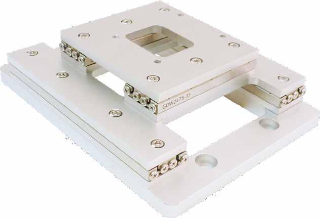
38 LINEAR POSITIONERS SLC-2475 Nanometer Precision Linear Positioner resolution travel range N normal load non magnetic vacuum size < 1 nm 49 mm 30 N (3 kg) available down to mbar 75 x 24 x 10.5 mm 3 Mechanical Properties blocking force F B max. normal force F N max. lift force F L > 3.5 N 30 N > 1.5 N positioner dimension 75 x 24 x 10.5 mm 3 weight pitch torque M P yaw torque M Y roll torque M R 90 g 18.1 Nm 18.1 Nm 3.9 Nm Positioning travel ± 24.5 (49) mm step width 1-1,500 nm* Closed-Loop with -S scan range > 1.5 μm sensor resolution 1 nm scan resolution < 1 nm repeatability ± 75 nm** velocity > 20 mm/s Closed-Loop with -L*** max. frequency 18.5 k Hz Materials and Vacuum Options**** steel base (-ST), titanium base (-TI) non magnetic materials (-NM) black anodized (-BK) sensor resolution closed loop resolution repeatability 4 nm ± 500 nm (H)CU 4 nm MCS ± 1 μm (H)CU ± 150 nm MCS Closed-Loop with -M*** integrated connecting elements (-O) external support for increased M Y, M R (-W) high precision bearing (-P) increased blocking force (-D, +1.5 N) -HV (10-6 mbar), -UHV / -UHVT (10-11 mbar) sensor resolution closed loop resolution repeatability 100 nm 500 nm (H)CU 100 nm MCS ± 2.5 μm (H)CU ± 0.5 µm MCS n3h7 x3.5 5x M3 x x M2 x 3.5 Linear dimensions are given in mm. 18 * for low-vibration mode (-LV), for scan-mode < 1 nm, otherwise 50-1,500 nm ** measured over the complete travel range, for shorter travel much better *** with mechanical end stops, 3 mm reduced travel **** positioner dimensions, mounting holes and travel range may vary and can be customized
39 LINEAR POSITIONERS resolution travel range N normal load non magnetic vacuum size SLC-2490 Nanometer Precision Linear Positioner < 1 nm 63 mm 30 N (3 kg) available down to mbar 90 x 24 x 10.5 mm 3 Mechanical Properties blocking force F B max. normal force F N max. lift force F L > 3.5 N 30 N > 1.5 N positioner dimension 90 x 24 x 10.5 mm 3 weight pitch torque M P yaw torque M Y roll torque M R 108 g 29.5 Nm 29.5 Nm 4.8 Nm Positioning travel ± 31.5 (63) mm step width 1-1,500 nm* Closed-Loop with -S scan range > 1.5 μm sensor resolution 1 nm scan resolution < 1 nm repeatability ± 90 nm** velocity > 20 mm/s Closed-Loop with -L*** max. frequency 18.5 k Hz Materials and Vacuum Options**** steel base (-ST), titanium base (-TI) non magnetic materials (-NM) black anodized (-BK) sensor resolution closed loop resolution repeatability 4 nm ± 500 nm (H)CU 4 nm MCS ± 1 μm (H)CU ± 180 nm MCS Closed-Loop with -M*** integrated connecting elements (-O) external support for increased M Y, M R (-W) high precision bearing (-P) increased blocking force (-D, +1.5 N) -HV (10-6 mbar), -UHV / -UHVT (10-11 mbar) sensor resolution closed loop resolution repeatability 100 nm 500 nm (H)CU 100 nm MCS ± 2.5 μm (H)CU ± 0.5 µm MCS n3h7 x3.5 6x M3 x x M2 x 3.5 Linear dimensions are given in mm. 19 * for low-vibration mode (-LV), for scan-mode < 1 nm, otherwise 50-1,500 nm ** measured over the complete travel range, for shorter travel much better *** with mechanical end stops, 3 mm reduced travel **** positioner dimensions, mounting holes and travel range may vary and can be customized
40 LINEAR POSITIONERS SLC Nanometer Precision Linear Positioner resolution travel range N normal load non magnetic vacuum size < 1 nm 69 mm 30 N (3 kg) available down to mbar 105 x 24 x 10.5 mm 3 Mechanical Properties blocking force F B max. normal force F N max. lift force F L > 3.5 N 30 N > 1.5 N positioner dimension 105 x 24 x 10.5 mm 3 weight pitch torque M P yaw torque M Y roll torque M R 126 g 37.5 Nm 37.5 Nm 5.8 Nm Positioning travel ± 34.5 (69) mm step width 1-1,500 nm* Closed-Loop with -S scan range > 1.5 μm sensor resolution 1 nm scan resolution < 1 nm repeatability ± 105 nm** velocity > 20 mm/s Closed-Loop with -L*** max. frequency 18.5 k Hz sensor resolution 4 nm Materials and Vacuum Options**** steel base (-ST), titanium base (-TI) non magnetic materials (-NM) closed loop resolution repeatability ± 500 nm (H)CU 4 nm MCS ± 1 μm (H)CU ± 210 nm MCS black anodized (-BK) integrated connecting elements (-O) sensor resolution Closed-Loop with -M*** 100 nm external support for increased M Y, M R (-W) high precision bearing (-P) increased blocking force (-D, +1.5 N) -HV (10-6 mbar), -UHV / -UHVT (10-11 mbar) closed loop resolution repeatability 500 nm (H)CU 100 nm MCS ± 2.5 μm (H)CU ± 0.5 µm MCS n3h7 x3.5 7x M3 x x M2 x 3.5 Linear dimensions are given in mm. 20 * for low-vibration mode (-LV), for scan-mode < 1 nm, otherwise 50-1,500 nm ** measured over the complete travel range, for shorter travel much better *** with mechanical end stops, 3 mm reduced travel **** positioner dimensions, mounting holes and travel range may vary and can be customized
41 LINEAR POSITIONERS resolution travel range N normal load non magnetic vacuum size SLC Nanometer Precision Linear Positioner < 1 nm 83 mm 30 N (3 kg) available down to mbar 120 x 24 x 10.5 mm 3 Mechanical Properties blocking force F B max. normal force F N max. lift force F L > 3.5 N 30 N > 1.5 N positioner dimension 120 x 24 x 10.5 mm 3 weight pitch torque M P yaw torque M Y roll torque M R 144 g 49.1 Nm 49.1 Nm 6.1 Nm Positioning travel ± 41.5 (83) mm step width 1-1,500 nm* Closed-Loop with -S scan range > 1.5 μm sensor resolution 1 nm scan resolution < 1 nm repeatability ± 120 nm** velocity > 20 mm/s Closed-Loop with -L*** max. frequency 18.5 k Hz sensor resolution 4 nm Materials and Vacuum Options**** steel base (-ST), titanium base (-TI) non magnetic materials (-NM) closed loop resolution repeatability ± 500 nm (H)CU 4 nm MCS ± 1 μm (H)CU ± 240 nm MCS black anodized (-BK) integrated connecting elements (-O) sensor resolution Closed-Loop with -M*** 100 nm external support for increased M Y, M R (-W) high precision bearing (-P) increased blocking force (-D, +1.5 N) -HV (10-6 mbar), -UHV / -UHVT (10-11 mbar) closed loop resolution repeatability 500 nm (H)CU 100 nm MCS ± 2.5 μm (H)CU ± 0.5 µm MCS n3h7 x3.5 8x M3 x x M2 x 3.5 Linear dimensions are given in mm. 21 * for low-vibration mode (-LV), for scan-mode < 1 nm, otherwise 50-1,500 nm ** measured over the complete travel range, for shorter travel much better *** with mechanical end stops, 3 mm reduced travel **** positioner dimensions, mounting holes and travel range may vary and can be customized

42 LINEAR POSITIONERS SLC Nanometer Precision Linear Positioner resolution travel range N normal load non magnetic vacuum size < 1 nm 103 mm 30 N (3 kg) available down to mbar 150 x 24 x 10.5 mm 3 Mechanical Properties blocking force F B max. normal force F N max. lift force F L > 3.5 N 30 N > 1.5 N positioner dimension 150 x 24 x 10.5 mm 3 weight pitch torque M P yaw torque M Y roll torque M R 180 g 49.1 Nm 49.1 Nm 6.1 Nm Positioning travel ± 51.5 (69) mm step width 1-1,500 nm* Closed-Loop with -S scan range > 1.5 μm sensor resolution 1 nm scan resolution < 1 nm repeatability ± 150 nm** velocity > 20 mm/s Closed-Loop with -L*** max. frequency 18.5 k Hz sensor resolution 4 nm Materials and Vacuum Options**** steel base (-ST), titanium base (-TI) non magnetic materials (-NM) closed loop resolution repeatability ± 500 nm (H)CU 4 nm MCS ± 1 μm (H)CU ± 300 nm MCS black anodized (-BK) integrated connecting elements (-O) sensor resolution Closed-Loop with -M*** 100 nm external support for increased M Y, M R (-W) high precision bearing (-P) increased blocking force (-D, +1.5 N) -HV (10-6 mbar), -UHV / -UHVT (10-11 mbar) closed loop resolution repeatability 500 nm (H)CU 100 nm MCS ± 2.5 μm (H)CU ± 0.5 µm MCS n3h7 x3.5 10x M3 x x M2 x 3.5 Linear dimensions are given in mm. 22 * for low-vibration mode (-LV), for scan-mode < 1 nm, otherwise 50-1,500 nm ** measured over the complete travel range, for shorter travel much better *** with mechanical end stops, 3 mm reduced travel **** positioner dimensions, mounting holes and travel range may vary and can be customized

43 LINEAR POSITIONERS resolution travel range N normal load non magnetic vacuum size SLC Nanometer Precision Linear Positioner < 1 nm 123 mm 30 N (3 kg) available down to mbar 180 x 24 x 10.5 mm 3 Mechanical Properties blocking force F B max. normal force F N max. lift force F L > 3.5 N 30 N > 1.5 N positioner dimension 180 x 24 x 10.5 mm 3 weight pitch torque M P yaw torque M Y roll torque M R 216 g 49.1 Nm 49.1 Nm 6.1 Nm Positioning travel ± 61.5 (123) mm step width 1-1,500 nm* Closed-Loop with -S scan range > 1.5 μm sensor resolution 1 nm scan resolution < 1 nm repeatability ± 180 nm** velocity > 20 mm/s Closed-Loop with -L*** max. frequency 18.5 k Hz sensor resolution 4 nm Materials and Vacuum Options**** steel base (-ST), titanium base (-TI) non magnetic materials (-NM) black anodized (-BK) closed loop resolution repeatability ± 500 nm (H)CU 4 nm MCS ± 1 μm (H)CU ± 360 nm MCS Closed-Loop with -M*** integrated connecting elements (-O) external support for increased M Y, M R (-W) high precision bearing (-P) increased blocking force (-D, +1.5 N) -HV (10-6 mbar), -UHV / -UHVT (10-11 mbar) sensor resolution closed loop resolution repeatability 100 nm 500 nm (H)CU 100 nm MCS ± 2.5 μm (H)CU ± 0.5 µm MCS x M2 x n2h7 x x M1.6 x 3.5 Linear dimensions are given in mm. 23 * for low-vibration mode (-LV), for scan-mode < 1 nm, otherwise 50-1,500 nm ** measured over the complete travel range, for shorter travel much better *** with mechanical end stops, 3 mm reduced travel **** positioner dimensions, mounting holes and travel range may vary and can be customized
 vacuum down to 10-6 mbar size 54 x 60 x 13 mm 3 Mechanical Properties blocking force F B 1.6 N max. normal force F N 1 N max. lift force F L 0.")
44 LINEAR POSITIONERS SL SERIES SL-06 Nanometer Precision Linear Positioner resolution < 1 nm travel range mm N normal load 30 N (3 kg) vacuum down to 10-6 mbar size 54 x 60 x 13 mm 3 Mechanical Properties blocking force F B 1.6 N max. normal force F N 1 N max. lift force F L 0.35 N positioner dimension 150 x 24 x 10.5 mm 3 weight 3-9 g pitch torque M P 0.1 Nm yaw torque M Y 0.1 Nm roll torque M R 0.1 Nm Positioning travel ± 51.5 (69) mm step width 1-1,500 nm resolution of motion 50 nm velocity > 15 mm/s max. frequency 18.5 khz Materials and Vacuum Options -HV (10-6 mbar), -UHV / -UHVT (10-11 mbar) 24


 mm 6 g positioner dimension 21 x 11 x 5.")


45 LINEAR POSITIONERS SL-06xx Nanometer Precision Linear Positioner SL-0610 travel weight ± 2.25 (4.5) mm 3 g positioner dimension 11 x 11 x 5.2 mm 3 4 x M1x0.25 x1 2 x M1x0.25 x x n SL-0620 travel weight ± 5.5 (11) mm 6 g positioner dimension 21 x 11 x 5.2 mm x M1x0.25 x1 4 x M1x0.25 x x n SL-0630 travel weight ± 8 (16) mm 9 g positioner dimension 31 x 11 x 5.2 mm x M1x0.25 x1 6 x M1x0.25 x x n Linear dimensions are given in mm. * other travel ranges upon request 25


46 LINEAR POSITIONERS SLL SERIES Nanometer Precision Linear Rail Positioner Positioners from the SLL line are based on recirculating ball slides. The small slide in combination with rails of different length make it an interesting solution either for precise long range positioning or if you need large travel ranges within limited space. It is possible to put multiple slides on the same rail. SLL positioners can be operated by any of our control units and are also available for high vacuum. SLL ACCESSORIES In order to use the SLL positioners as an optical bench SmarAct offers a large variety of equipment, including adapter plates. This allows easy integration of the piezo driven rails into your experimental setup. A small selection of the broad SLL product variety is given below. If you require special parts, please don t hesitate to contact us. Passive Carrier To mount existing components or other positioners onto the same rail we offer a passive carrier which is equipped with a clamp for fixation. Endstop Bracket In order to limit the travel range of SLL positioners we are offering removable and fixed endstops. Breadboard adapter To mount the rail to an existing bread board we are offering mounting adapters and variable end stops which are available for every common hole pattern. Optomechanical mounts To attach optomechanical components to the rails, various mounts are available, too. 26

47 LINEAR POSITIONERS resolution travel range N normal load vacuum size SLL12 Nanometer Precision Linear Positioner < 1 nm mm 30N (3 kg) down to 10-6 mbar 33.8 x 27 x 13 mm³ Mechanical Properties blocking force F B max. normal force F N max. lift force F L > 3 N 30 N > 1 N carriage dimension 33.8 x 27 x 13 mm 3 weight of carriage 44 g weight of rail 59 g / 100 mm pitch torque M P 6 Nm yaw torque M Y 6 Nm roll torque M R 11 Nm Positioning rail length mm step width 1-1,500 nm* scan range > 1.5 μm scan resolution < 1 nm velocity > 20 mm/s max. frequency 18.5 khz Materials and Vacuum Options*** multiple carriages counterbores, tapped holes (M4) tapped holes M4 necessary for closed-loop -HV (10-6 mbar)*** Closed-Loop with -S sensor resolution 1 nm repeatability ± nm** Closed-Loop with -M sensor resolution 100 nm closed loop resolution 500 nm (H)CU 100 nm MCS repeatability ± 2.5 μm (H)CU ± 0.5 µm MCS x M3 x3 A A Section A-A Ø 3.5 Ø SLL12 open-loop version, linear dimensions are given in mm. *** * for low-vibration mode (-LV), for scan-mode < 1 nm, otherwise 50-1,500 nm ** measured over the complete travel range, for shorter travel much better *** positioner dimensions, mounting holes and travel range may vary and can be customized 27
 54 x 60 x 13 mm 3 Mechanical Properties blocking force F B max. normal force F N max. lift force F L > 5 N 30 N > 1.")
48 LINEAR POSITIONERS SLLA42 Nanometer Precision Linear Positioner resolution travel range N normal load size < 1 nm mm 30 N (3 kg) 54 x 60 x 13 mm 3 Mechanical Properties blocking force F B max. normal force F N max. lift force F L > 5 N 30 N > 1.5 N carriage dimension 54 x 60 x 16 mm 3 weight of carriage 148 g weight of rail 286 g / 100 mm pitch torque M P 25 Nm yaw torque M Y 25 Nm roll torque M R 90 Nm Positioning rail length mm step width 1-1,500 nm* scan range > 3 μm scan resolution < 1 nm velocity > 20 mm/s max. frequency 18.5 khz Materials and Vacuum Options*** multiple carriages counterbores, tapped holes (M4) sensor resolution repeatability Closed-Loop with -S 1 nm ± nm** x M4 x4 A A 16 Section A-A 4.5 Linear dimensions are given in mm.*** 28 * for low-vibration mode (-LV), for scan-mode < 1 nm, otherwise 50-1,500 nm ** measured over the complete travel range, for shorter travel much better *** positioner dimensions, mounting holes and travel range may vary and can be customized


49 LINEAR POSITIONERS resolution travel range N normal load vacuum size SLLV42 Nanometer Precision Linear Positioner < 1 nm mm 30 N (3 kg) down to 10-6 mbar 54.8 x 60 x 13 mm 3 Mechanical Properties blocking force F B max. normal force F N max. lift force F L > 5 N 30 N > 1.5 N carriage dimension 54.8 x 60 x 16 mm 3 weight of carriage 148 g weight of rail 286 g / 100 mm pitch torque M P 25 Nm yaw torque M Y 25 Nm roll torque M R 90 Nm Positioning rail length mm step width 1-1,500 nm* scan range > 3 μm scan resolution < 1 nm velocity > 20 mm/s max. frequency 18.5 khz Materials and Vacuum Options*** multiple carriages counterbores, tapped holes (M4) -HV (10-6 mbar)*** external support for increased M Y, M R (-W) high precision bearing (-P) increased blocking force (-D, +1.5 N) -HV (10-6 mbar) Closed-Loop with -S sensor resolution 1 nm repeatability ± nm** Closed-Loop with -M sensor resolution 100 nm closed loop resolution 500 nm (H)CU 100 nm MCS repeatability ± 2.5 μm (H)CU ± 0.5 µm MCS x M4 x4 A A Section A-A Ø 4.5 Ø 8 Linear dimensions are given in mm.*** * for low-vibration mode (-LV), for scan-mode < 1 nm, otherwise 50-1,500 nm ** measured over the complete travel range, for shorter travel much better *** positioner dimensions, mounting holes and travel range may vary and can be customized 29

50 LINEAR POSITIONERS SHL SERIES N SHL 20N-10 Nanometer Precision Linear Positioner resolution < 1 nm travel range 11 mm normal load 20 N (2 kg) vacuum down to mbar size 65 x 75 x 50 mm 3 Mechanical Properties max. normal force F N max. lift force F L 20 N 20 N positioner dimension 65 x 75 x 50 mm 3 weight 200 g Positioning travel ± 5 (10) mm step width 1-1,500 nm* scan range > 500 nm scan resolution < 1 nm velocity > 9 mm/s max. frequency 10 khz Materials and Vacuum Options*** steel base (-ST), titanium base (-TI) black anodized (-BK) -M sensor on Demand (-M) -HV (10-6 mbar), -UHV / -UHVT (10-11 mbar) Closed-Loop with -S sensor resolution 1 nm repeatability ± 100 nm ** Closed-Loop with -L sensor resolution 4 nm closed loop resolution ± 500 nm (H)CU 4 nm MCS repeatability ± 1 μm (H)CU ± 200 nm MCS 25 x M3 x x15 75 Linear dimensions are given in mm. 30 * for low-vibration mode (-LV), for scan-mode < 1 nm, otherwise 50-1,500 nm ** measured over the complete travel range, for shorter travel much better *** with mechanical end stops, 3 mm reduced travel

51 LINEAR POSITIONERS 31
52 32
53 About SmarAct SmarAct develops high-performance solutions for handling and positioning in the micro- and nanometer range. The broad product portfolio - from single positioners to complex parallel kinematics, miniaturized robots and easy-to-use control systems - is completed by sophisticated measuring equipment based on powerful laser interferometers. We serve high accuracy positioning and metrology applications in research and industry within such fields as optics, life sciences, micro-assembly, semiconductors and microscopy. Maintaining the complete production in house allows a high level of customization so that we can always provide you the optimal individual or OEM solution. HEADQUARTERS SmarAct GmbH Schuette-Lanz-Strasse Oldenburg Germany T: info-de@smaract.com USA SmarAct Inc Shattuck Ave., Suite 1103 Berkeley, CA United States of America T: info-us@smaract.com 07/2017


54 ROTARY POSITIONERS Piezo-based high-performance rotary micro- and nanopositioners
55 Copyright 2017 SmarAct GmbH Specifications are subject to change without notice. All rights reserved. Reproduction of images, tables or diagrams prohibited. The information given in this catalog was carefully checked by our team and is constantly updated. Nevertheless it is not possible to fully exclude the presence of errors. In order to always get the latest information, please contact our technical sales team. SmarAct GmbH, Schuette-Lanz-Straße 9, D Oldenburg Phone: +49 (0) , Telefax: +49 (0) Internet: 1
56
57 TABLE OF CONTENTS ABOUT ROTARY POSITIONERS...4 SR SR SR SR SR SR SR SR-5714C...12 SR SR SR
58 ROTARY POSITIONERS ABOUT ROTARY POSITIONERS High-Precision Rotary Positioners SmarAct is offering different piezo-based rotary positioners with unlimited rotation. The motors define the strength and speed, the used sensor the closed-loop resolution, whereas the bearing defines the size and rigidity of the rotary positioner. Some rotary positioners are based on four-point bearings. For example the SR-1908 rotary positioner is very compact and provides a 7 mm aperture, which makes it suitable for applications with limited space. The SR-2013-S is an exceptionally compact, closed-loop nano positioner which can be delivered in a non-magnetic version, with an integrated preloaded ceramic bearing. The SR-4513, SR-5714 and SR-7021 rotary positioners are based on crossed roller bearings. The SR-4011, SR-7012 and SR are based on deep groove ball bearings. All of these rotary positioners are very rigid and allow high loads to be applied. Product Line Positioner Series SR SR SR SR SR SR SR SR SR- 5714C SR SR SR Mechanical Open-Loop Closed-Loop blocking torque [Ncm] max. normal force [N] dimensions [mm 2 ] x x x x40 45 x x x x x x 90 height [mm] weight [g] aperture [mm] stage diameter [mm] travel [ ] step width [m ] scan range [m ] scan resolution [μ ] < 2 < 1 < 1 < 1 < 1 < 0.5 < 0.5 < 0.5 < 0.5 < 1 angular speed [ /s] max. frequency [khz] sensor types -S -S closedloop resolution [μ ] -M MCS (H)CU -L MCS (H)CU vacuum compatibility -M, -L, -S I, -M, -L, -S M, -L, -S x 120 -S -S -S -S -S -S MCS HV HV, UHV HV, UHV HV HV HV HV HV, UHV HV HV, UHV HV 4

59 ROTARY POSITIONERS N SR-1908 High-Precision Rotary Positioners resolution rotation normal load vacuum size < 300 μ 5 N (500 g) 10-6 mbar 24.7 x 20 x 8.5 mm 3 Mechanical Properties blocking torque M B max. normal force F N 0.5 Ncm 5 N positioner dimensions 24.7 x 20 x 8.5 mm 3 stage diameter aperture weight Ø 19 mm Ø 7 mm 13 g Positioning travel step width m angular velocity 45 /s max. frequency 18.5 khz Materials and Vacuum Options* steel base (-ST) hard end stops, sample stub holder The SR-1908 is SmarAct s smallest standard rotary positioner. The very robust stainless steel bearing together with an aperture of 7 mm enables a broad range of possible applications. -HV (10-6 mbar) 4x M1.6 x x n Linear dimensions are given in mm. 5 * positioner dimensions, mounting holes and travel range may vary and can be customized

60 ROTARY POSITIONERS SR-2013 High-Precision Rotary Positioners resolution rotation non magnetic N normal load vacuum size < 2 μ available 3 N (300 g) mbar 25.5 x 20 x 10.2 mm³ Mechanical Properties blocking torque M B 0.5 Ncm max. normal force F N 3 N positioner dimensions 25.5 x 20 x 10.2 mm 3 stage diameter Ø 15 mm weight 11 g Positioning travel step width m scan range > 8 m scan resolution < 2 µ angular velocity 45 /s max. frequency 18.5 khz Materials and Vacuum Options steel base (-ST), titanium base (-TI) non-magnetic materials (-NM) -HV (10-6 mbar), -UHV / -UHVT (10-11 mbar) Clodsed-Loop with -S sensor resolution 25 µ closed-loop resolution 25 µ MCS/SDC The SR-2013 is our lightest and smallest closed-loop rotary positioner. An integrated ceramic precision bearing is the reason for the ultra-high accuracy as well as the extremely low radial run-out. 2x M1.6 x 2.5 mm 4x M1.6 x n9.5 n x M1.6 x 1.0 mm Linear dimensions are given in mm. 6 * positioner dimensions, mounting holes and travel range may vary and can be customized

61 ROTARY POSITIONERS resolution rotation non magnetic N normal load vacuum size SR-2812 High-Precision Rotary Positioners < 1 µ available 3 N (300 g) 10-6 mbar 24.7 x 20 x 8.5 mm 3 Mechanical Properties blocking torque M B max. normal force F N 3 N cm 3 N positioner dimensions 37.5 x 30 x 12 mm 3 stage diameter Ø 28 mm aperture Ø 9 mm weight 35 g Positioning travel step width m scan range > 4 m scan resolution < 1 µ angular velocity 5 /s max. frequency 18.5 k Hz Materials and Vacuum Options* steel base (-ST), titanium base (-TI) non-magnetic materials (-NM) -HV (10-6 mbar), -UHV / -UHVT (10-11 mbar) Clodsed-Loop with -S sensor resolution 25 µ closed-loop resolution 25 µ MCS/SDC The SR-2812 is the smallest closed-loop rotary positioner with an aperture of 9 mm. An integrated ceramic precision bearing is the reason for the ultra-high accuracy as well as the extremely low radial run-out. 4x 1 n.6 n9 n x M2 x Aperture: 9 mm Linear dimensions are given in mm. * positioner dimensions, mounting holes and travel range may vary and can be customized 7

62 ROTARY POSITIONERS SR-4011 High-Precision Rotary Positioners resolution rotation N normal load vacuum size < 1 μ 10 N (1 kg) down to 10-6 mbar 40 x 40 x 11 mm³ Mechanical Properties blocking torque M B 5 Ncm max. normal force F N 10 N positioner dimensions 40 x 40 x 11 mm 3 stage diameter Ø 31 mm aperture Ø 9 mm weight 60 g Positioning travel step width m scan range > 4 m scan resolution < 1 µ angular velocity 15 /s max. frequency 18.5 khz Materials and Vacuum Options* steel base (-ST), titanium base (-TI) hard end stops (-E) higher blocking force (-D) -HV (10-6 mbar) Clodsed-Loop with -S sensor resolution 15 µ closed-loop resolution 15 μ MCS/SDC Clodsed-Loop with -L sensor resolution 60 µ closed-loop resolution 60 μ MCS/SDC 1 m (H)CU Clodsed-Loop with -M sensor resolution 500 µ closed-loop resolution 500 μ MCS/SDC 1 m (H)CU M2 (4x) max. depth 4mm 40 Ø31 30 Ø20 Ø x Ø3.2 Aperture: 7 mm Linear dimensions are given in mm. 8 * positioner dimensions, mounting holes and travel range may vary and can be customized

63 ROTARY POSITIONERS resolution rotation N normal load vacuum size SR-4513 High-Precision Rotary Positioners < 1 μ 20 N (2 kg) 10-6 mbar 45 x 45 x 13.5 mm³ Mechanical Properties blocking torque M B max. normal force F N 5 Ncm 20 N positioner dimensions 45 x 45 x 13.5 mm 3 stage diameter aperture weight travel Ø 36 mm Ø 8 mm 89 g Positioning step width m scan range > 4 m scan resolution < 1 µ angular velocity max. frequency 15 /s 18.5 khz Materials and Vacuum Options* steel base (-ST), titanium base (-TI) hard end stops (-E) higher blocking force (-D) -HV (10-6 mbar) Due to the high-load stainless steel bearing, the SR is very robust. Compared to the footprint, the height is relatively low, making this positioner an excellent choice for integration into flat positioning systems. Clodsed-Loop with -S sensor resolution 15 µ closed-loop resolution 15 μ MCS/SDC Clodsed-Loop with -L sensor resolution 60 µ closed-loop resolution 60 μ MCS/SDC 1 m (H)CU Clodsed-Loop with -L sensor resolution 500 µ closed-loop resolution 500 μ MCS/SDC 1 m (H)CU 35 n x M3 x 4 n x n3.3 Aperture: 9 mm Linear dimensions are given in mm. * positioner dimensions, mounting holes and travel range may vary and can be customized 9

64 ROTARY POSITIONERS SR-5018 High-Precision Rotary Positioners N resolution rotation normal load vacuum size < 1 μ 20 N (2 kg) down to 10-6 mbar 50 x 50 x 16.5 mm³ Mechanical Properties blocking torque M B max. normal force F N 7 Ncm 20 N positioner dimensions 50 x 50 x 16.5 mm 3 stage diameter aperture weight Ø 41 mm Ø 8 mm 100 g Positioning travel step width m scan range > 3.8 m scan resolution < 1 µ Clodsed-Loop with -S angular velocity 15 /s sensor resolution 15 µ max. frequency 18.5 khz closed-loop resolution 15 μ MCS/SDC Materials and Vacuum Options* steel base (-ST), titanium base (-TI) Clodsed-Loop with -L sensor resolution 60 µ hard end stops (-E) closed-loop resolution 60 μ MCS/SDC higher blocking force (-D) -HV (10-6 mbar) 1 m (H)CU Clodsed-Loop with -M sensor resolution 500 µ closed-loop resolution 500 μ MCS/SDC 1 m (H)CU x M2 x 2.0 n x Aperture: 8 mm Linear dimensions are given in mm. 10 * positioner dimensions, mounting holes and travel range may vary and can be customized
 down to 10-6 mbar 57 x 57 x 14 mm³ Mechanical Properties blocking torque M B 5 N cm max.")
65 ROTARY POSITIONERS resolution rotation N normal load vacuum size SR-5714 High-Precision Rotary Positioners < 0.5 μ 25 N (2.5 kg) down to 10-6 mbar 57 x 57 x 14 mm³ Mechanical Properties blocking torque M B 5 N cm max. normal force F N 25 N positioner dimensions 57 x 57 x 14 mm 3 stage diameter Ø 57 mm aperture Ø 25 mm weight 110 g Positioning travel step width m scan range > 2.3 m scan resolution < 0.5 µ angular velocity 9 /s max. frequency 18.5 khz Materials and Vacuum Options* steel base (-ST), titanium base (-TI) higher blocking force (-D) -HV (10-6 mbar) Clodsed-Loop with -S sensor resolution 15 µ closed-loop resolution 15 µ MCS/SDC Designed with an aperture of 25 mm, the robust SR can be used for a broad range of applications. 4x M3.0 x5.0 n25 n44 n x M2.0 x Aperture: 25 mm Linear dimensions are given in mm. * positioner dimensions, mounting holes and travel range may vary and can be customized 11

66 ROTARY POSITIONERS SR-5714C High-Precision Rotary Positioners resolution rotation N normal load non magnetic vacuum size < 0.5 μ 25 N (2.5 kg) available down to mbar 57 x 57 x mm³ Mechanical Properties blocking torque M B 5 N cm max. normal force F N 25 N positioner dimensions 57 x 57 x mm 3 stage diameter Ø 48 mm aperture Ø 25 mm weight 105 g Positioning travel step width m scan range > 2.3 m scan resolution < 0.5 µ angular velocity 9 /s max. frequency 18.5 khz Materials and Vacuum Options* steel base (-ST), titanium base (-TI) non-magnetic materials (-NM) higher blocking force (-D) -HV (10-6 mbar), -UHV / -UHVT (10-11 m bar) Clodsed-Loop with -S sensor resolution 15 µ closed-loop resolution 15 µ MCS/SDC This robust positioner can be used also for applications in harsh environments, down to ultra-high vacuum environments. n30 n44 n57 n25 n30 n40 8x M2 x x M2 Aperture: 25 mm Linear dimensions are given in mm. 12 * positioner dimensions, mounting holes and travel range may vary and can be customized
 down to 10-6 mbar 70 x 70 x 12 mm³ Mechanical Properties blocking torque M B 10 Ncm max.")
67 ROTARY POSITIONERS resolution rotation N normal load vacuum size SR-7012 High-Precision Rotary Positioners < 0.5 μ 25 N (2.5 kg) down to 10-6 mbar 70 x 70 x 12 mm³ Mechanical Properties blocking torque M B 10 Ncm max. normal force F N 25 N positioner dimensions 70 x 70 x 12 mm³ stage diameter Ø 60 mm aperture Ø 30 mm weight 100 g Positioning travel step width m scan range > 2.5 m scan resolution < 0.5 µ angular velocity 9 /s max. frequency 18.5 khz Materials and Vacuum Options* steel base (-ST), titanium base (-TI) higher blocking force (-D) -HV (10-6 mbar) Clodsed-Loop with -S sensor resolution 15 µ closed-loop resolution 15 µ MCS/SDC 4 x Ø x M3 4 Ø Linear dimensions are given in mm. * positioner dimensions, mounting holes and travel range may vary and can be customized 13
 available down to 10-11 mbar 90 x 90 x 21 mm³ Mechanical Properties blocking torque M B max.")
68 ROTARY POSITIONERS SR-7021 High-Precision Rotary Positioners resolution rotation N normal load non magnetic vacuum size < 0.5 μ 25 N (2.5 kg) available down to mbar 90 x 90 x 21 mm³ Mechanical Properties blocking torque M B max. normal force F N 10 Ncm 25 N positioner dimensions 90 x 90 x 21 mm 3 stage diameter aperture weight Ø 70 mm Ø 25 mm 400 g Positioning travel step width m scan range > 3.1 m scan resolution < 0.5 µ Clodsed-Loop with -S angular velocity max. frequency 9 /s 18.5 khz sensor resolution 15 µ closed-loop resolution 15 µ MCS/SDC Materials and Vacuum Options* steel base (-ST), titanium base (-TI) non-magnetic materials (-NM) higher blocking force (-D) -HV (10-6 mbar), -UHV / -UHVT (10-11 m bar) Currently, the SR-7021 is our strongest rotary positioner and frequently chosen for heavy duty applications. 4x M3 x n90 8x 4 n.1 n n80 Aperture: 82 mm Linear dimensions are given in mm. 14 * positioner dimensions, mounting holes and travel range may vary and can be customized

, titanium base (-TI) higher blocking force (-D) -HV (10-6 mbar) Clodsed-Loop with -S sensor resolution 5 µ closed-loop resolution 5 µ MCS/SDC At")
69 ROTARY POSITIONERS resolution rotation N normal load vacuum size SR High-Precision Rotary Positioners < 1 μ 20 N (2 kg) down to 10-6 mbar 120 x 120 x 12 mm³ Mechanical Properties blocking torque M B max. normal force F N 15 Ncm 20 N positioner dimensions 120 x 120 x 12 mm 3 stage diameter Ø 110 mm aperture Ø 82 mm weight 320 g Positioning travel step width m scan range > 4.0 m scan resolution < 1 µ angular velocity 10 /s max. frequency 18.5 khz Materials and Vacuum Options* steel base (-ST), titanium base (-TI) higher blocking force (-D) -HV (10-6 mbar) Clodsed-Loop with -S sensor resolution 5 µ closed-loop resolution 5 µ MCS/SDC At the moment, the SR is our biggest rotary positioner and mostly chosen for special applications where a big aperture and highest precision is absolutely essential. 4 x M Ø110 Ø Ø x Ø3.20 Aperture: 82 mm Linear dimensions are given in mm. * positioner dimensions, mounting holes and travel range may vary and can be customized 15
70 16
71 About SmarAct SmarAct develops high-performance solutions for handling and positioning in the micro- and nanometer range. The broad product portfolio - from single positioners to complex parallel kinematics, miniaturized robots and easy-to-use control systems - is completed by sophisticated measuring equipment based on powerful laser interferometers. We serve high accuracy positioning and metrology applications in research and industry within such fields as optics, life sciences, micro-assembly, semiconductors and microscopy. Maintaining the complete production in house allows a high level of customization so that we can always provide you the optimal individual or OEM solution. HEADQUARTERS SmarAct GmbH Schuette-Lanz-Strasse Oldenburg Germany T: info-de@smaract.com USA SmarAct Inc Shattuck Ave., Suite 1103 Berkeley, CA United States of America T: info-us@smaract.com 07/2017


72 GONIOMETERS Stackable high-precision piezo goniometer for micro- and nanopositioning tasks
73 Copyright 2017 SmarAct GmbH Specifications are subject to change without notice. All rights reserved. Reproduction of images, tables or diagrams prohibited. The information given in this catalog was carefully checked by our team and is constantly updated. Nevertheless it is not possible to fully exclude the presence of errors. In order to always get the latest information, please contact our technical sales team. SmarAct GmbH, Schuette-Lanz-Straße 9, D Oldenburg Phone: +49 (0) , Telefax: +49 (0) Internet: 1
74
75 TABLE OF CONTENTS ABOUT GONIOMETERS...4 SGO SGO SGO


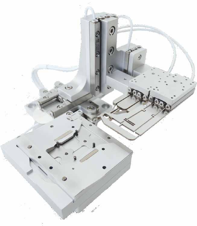
76 GONIOMETERS ABOUT GONIOMETERS Nanometer-Precision Piezo Goniometers Based on our piezo drive technologies, we are offering goniometers with different radii. In addition to their compactness, the goniometers of the SGO-series are very rigid and therefore ideally suited for micro- or nanopositioning tasks. Due to the usage of high precision crossed roller bearings, they provide a high angular accuracy. Our goniometers offer a high resolution of motion and are directly stackable. By combining two goniometers with appropriate ra- dii it is possible to build a compact Euler goniometer with a common center of rotation. The SmarAct goniometers can be operated by any of our control units and are also available with integrated positioning sensors. Furthermore, the SGO-series goniometers are available for different environmental conditions, such as high vacuum and ultra high vacuum environments. 3D Manipulator Stacked x-y-stage with SGO goniometer. 4
77 GONIOMETERS resolution rotation N normal load center of rotation vacuum size SGO Nanometer-Precision Piezo Goniometer < 2 µ (< 0.03 μrad) ± 5 5 N (500 g) 60.5 mm down to mbar 50 x 50 x 17 mm 3 Mechanical Properties blocking torque M B max. normal force F N lateral torque M R 20 Ncm 5 N 1.2 Nm positioner dimension 50 x 50 x 17 mm 3 center of rotation 60.5 mm weight 140 g Positioning travel ± 5 step width μrad scan range 10.5 μrad scan resolution 0.01 μrad velocity 4 /s max. frequency 18.5 khz Materials and Vacuum Options steel base (-ST) increased life time (-Z) -HV (10-6 mbar), -UHV / -UHVT (10-11 mbar) Closed-Loop with -S sensor resolution 0.03 μrad Closed-Loop with -L* sensor resolution 0.12 μrad 1.5 μrad (H)CU closed-loop resolution 0.12 μrad MCS sensor resolution closed-loop resolution Closed-Loop with -M* 1.5 μrad 4.5 μrad (H)CU 1.5 μrad MCS 70 4x n 2 x 5 n4 x x n 2 x2 n4.4x x M2 x x M2 x Linear dimensions are given in mm. * with mechanical end stops 5

 increased life time (-Z) -HV (10-6 mbar), -UHV / -UHVT (10-11 mbar) Closed-Loop with -S sensor resolution 0.")
78 GONIOMETERS SGO Nanometer-Precision Piezo Goniometer resolution rotation N normal load center of rotation vacuum size < 2 µ (< 0.03 μrad) ± 5 5 N (500 g) 77.5 mm down to mbar 50 x 50 x 17 mm 3 Mechanical Properties blocking torque M B max. normal force F N lateral torque M R 20 Ncm 5 N 1.2 Nm positioner dimension 50 x 50 x 17 mm 3 center of rotation 77.5 mm weight 140 g Positioning travel ± 5 step width μrad scan range 10.5 μrad scan resolution 0.01 μrad velocity 4 /s max. frequency 18.5 khz Materials and Vacuum Options steel base (-ST) increased life time (-Z) -HV (10-6 mbar), -UHV / -UHVT (10-11 mbar) Closed-Loop with -S sensor resolution 0.03 μrad Closed-Loop with -L* sensor resolution 0.12 μrad 1.5 μrad (H)CU closed-loop resolution 0.12 μrad MCS sensor resolution closed-loop resolution Closed-Loop with -M* 1.5 μrad 4.5 μrad (H)CU 1.5 μrad MCS 4x n 2 x 5 n4 x x n 2 x2 n4.4x x M2 x x M2 x Linear dimensions are given in mm. 6 * with mechanical end stops

79 GONIOMETERS resolution rotation N normal load center of rotation vacuum size SGO Nanometer-Precision Piezo Goniometer < 2 µ (< 0.03 μrad) ± 5 5 N (500 g) 93.5 mm down to mbar 50 x 50 x 17 mm 3 Mechanical Properties blocking torque M B max. normal force F N lateral torque M R 20 Ncm 5 N 1.2 Nm positioner dimension 50 x 50 x 17 mm 3 center of rotation 93.5 mm weight 140 g Positioning travel ± 5 step width μrad scan range 10.5 μrad scan resolution 0.01 μrad velocity 4 /s max. frequency 18.5 khz Materials and Vacuum Options steel base (-ST) increased life time (-Z) -HV (10-6 mbar), -UHV / -UHVT (10-11 mbar) Closed-Loop with -S sensor resolution 0.03 μrad Closed-Loop with -L* sensor resolution 0.12 μrad 1.5 μrad (H)CU closed-loop resolution 0.12 μrad MCS sensor resolution closed-loop resolution Closed-Loop with -M* 1.5 μrad 4.5 μrad (H)CU 1.5 μrad MCS x n 2 x 5 n4 x x n 2 x2 n4.4x x M2 x x M2 x Linear dimensions are given in mm. * with mechanical end stops 7
80 8
81 About SmarAct SmarAct develops high-performance solutions for handling and positioning in the micro- and nanometer range. The broad product portfolio - from single positioners to complex parallel kinematics, miniaturized robots and easy-to-use control systems - is completed by sophisticated measuring equipment based on powerful laser interferometers. We serve high accuracy positioning and metrology applications in research and industry within such fields as optics, life sciences, micro-assembly, semiconductors and microscopy. Maintaining the complete production in house allows a high level of customization so that we can always provide you the optimal individual or OEM solution. HEADQUARTERS SmarAct GmbH Schuette-Lanz-Strasse Oldenburg Germany T: info-de@smaract.com USA SmarAct Inc Shattuck Ave., Suite 1103 Berkeley, CA United States of America T: info-us@smaract.com 07/2017

82 MICRO-GRIPPERS Piezo-based gripper tools for your advanced handling demands
83 Copyright 2017 SmarAct GmbH Specifications are subject to change without notice. All rights reserved. Reproduction of images, tables or diagrams prohibited. The information given in this catalog was carefully checked by our team and is constantly updated. Nevertheless it is not possible to fully exclude the presence of errors. In order to always get the latest information, please contact our technical sales team. SmarAct GmbH, Schuette-Lanz-Straße 9, D Oldenburg Phone: +49 (0) , Telefax: +49 (0) Internet: 1
84
85 TABLE OF CONTENTS ABOUT MICRO-GRIPPERS...4 SG SG SGP-17F...7 STANDARD GRIPPER JAWS...8 CUSTOMIZED GRIPPER JAWS...8 3
 a linear positioner (eg.")


86 MICRO-GRIPPERS ABOUT MICRO-GRIPPERS Piezo-Based Gripper Tool SmarAct grippers (SG) are suitable for both microand macroscopic applications. Every gripper consists of two parts (a) a linear positioner (eg. SLC series) and (b) a flexure structure attached to the positioner. Depending on the application the gripper jaws are exchangeable or permanently welded to the positioner. Easily exchangeable jaws make your investment future proof. You can always work with exactly the jaw shape most suitable for your application. Due to the large travel ranges of SmarAct s positioners the grippers allow for an opening of up to several millimeters, while maintaining very precise control. This high precision is particularly important for the manipulation of small and fragile objects. The internal position sensors of the SLC series are of greatest importance, especially in automated microhandling, because they provide feedback on the success of a gripping process. Unlike most other micro-grippers, SmarAct grippers are able to hold objects even when there is no power supply, enabling long gripping times without any heat generation. All grippers can be designed to fit your needs. We look forward to discuss your individual requirements with you. 4
 Mechanical Properties gripping force gripping time gripping resolution gripper opening 0.3 N 100 ms < 100 nm 1 mm gripper dimension 11 x 18.")
87 MICRO-GRIPPERS resolution gripping force vacuum size SG-06 Piezo-Based Gripper Tool < 100 nm 0.3 N down to mbar 11 x 18.3 x 5 mm 3 (without jaw) Mechanical Properties gripping force gripping time gripping resolution gripper opening 0.3 N 100 ms < 100 nm 1 mm gripper dimension 11 x 18.3 x 5 mm 3 weight 2 g Materials and Vacuum Options exchangeable jaws (-EX) black anodized for optical applications (-BK) -HV (10-6 mbar), -UHV / UHVT (10-11 mbar) 2 x M1.6 x SLL12 open-loop version. Linear dimensions are given in mm. 5
 Mechanical Properties gripping force gripping time gripping resolution gripper opening 1 N < 10 ms < 10 nm > 1 mm gripper dimension 17 x 31.6 x 9.")
88 MICRO-GRIPPERS SG-1730 Piezo-Based Gripper Tool resolution gripping force vacuum size < 10 nm 1 N down to mbar 17 x 31.6 x 9.5 mm 3 (without jaw) Mechanical Properties gripping force gripping time gripping resolution gripper opening 1 N < 10 ms < 10 nm > 1 mm gripper dimension 17 x 31.6 x 9.5 mm 3 weight 25 g Materials and Vacuum Options exchangeable jaws (-EX) black anodized for optical applications (-BK) -HV (10-6 mbar), -UHV / UHVT (10-11 mbar) sensor feedback on request (-M, -S) Especially in automated microhandling the internal position sensors of the SLC series are of greatest importance since they provide feedback on the success of a gripping process. All SG-1730 micro-grippers are available with an integrated nano- (-S) or microsensor (-M), if sensor feedback is necessary for your specific application. 2 x M2 x Linear dimensions are given in mm. 6


89 MICRO-GRIPPERS resolution gripping force size SGP-17F Parallel Gripper with Force Feedback < 10 nm 3.5 N 35 x 30 x 14 mm 3 (without jaw) Mechanical Properties gripping force 3.5 N gripping time < 10 ms gripping resolution < 10 nm gripper opening > 10 mm gripper dimension 35 x 30 x 14 mm 3 weight 40 g Materials and Vacuum Options fully customizable jaws black anodized for optical applications (-BK) position sensor feedback (-M, -S) A new addition to the SmarAct gripper lineup comes in the shape of a parallel twin-biaxial force feedback gripper. This system uses a different mechanism than the SG-1730 and SG-06 type grippers. All three concepts serve unique purposes and allow for fundamentally new approaches to your advanced handling demands. The force-feedback gripper is equipped with one biaxial load cell per jaw, making it possible to detect both gripping force and orthogonal contact force individually for each jaw. Due to the perfectly parallel jaw movement, the gripping force orientation is constant over the entire travel range. This high level of flexibility makes the system ideal for handling variable or unreferenced workpieces. A wide range of jaw geometries can be fitted and exchanged to accommodate specific applications. 14 B 30 C C A A, B and C may vary depending on application. Linear dimensions are given in mm. Linear dimensions are given in mm. 7
90 MICRO-GRIPPERS STANDARD GRIPPER JAWS Piezo-Based Gripper Tool For various applications we offer different standard gripper jaws for both, grippers with a fixed gripper structure and with exchangeable gripper jaws. In the image below, you can find a small selection of different jaw shapes, which may also provide some ideas for your jaw design. Standard gripper jaws are made out of conductive materials like steel or copper beryllium. Other conductive as well as non-conductive materials are available on request. Standard gripper jaws for SG-06-EX (SGH-06-STD) Standard gripper jaws for SG-1730-EX (SGH-17-STD) CUSTOMIZED GRIPPER JAWS Piezo-Based Gripper Tool SmarAct offers customized gripper jaws for both, grippers with a fixed gripper structure and with exchangeable gripper jaws. Various structures like parallel grippers, slit apertures as well as cranked jaws have been designed and can be adapted to match your specifications. Like standard gripper jaws, our customized gripper jaws are made of conductive materials like steel or copper beryllium. Other conductive as well as non-conductive materials are available upon request. For us it is important to produce the optimal gripper for your application, so please feel free to contact us and our experts will help you design your gripper. We established a few design rules as given below: Please use our default model, which will be provided by us, keep the triangular part and only change the gripper jaws. The minimum concave radius is 0.11 mm. The minimum gap size is 0.22 mm. The material thickness should be 0.3 mm, 0.5 mm, 1.0 mm or 1.5 mm. Please send us the model in SolidWorks or STEP format. Micro-Gripper for Microassembly Customized micro-grippers SG-1730-S-EX used for the aligning of micro-optic components. 8
91 About SmarAct SmarAct develops high-performance solutions for handling and positioning in the micro- and nanometer range. The broad product portfolio - from single positioners to complex parallel kinematics, miniaturized robots and easy-to-use control systems - is completed by sophisticated measuring equipment based on powerful laser interferometers. We serve high accuracy positioning and metrology applications in research and industry within such fields as optics, life sciences, micro-assembly, semiconductors and microscopy. Maintaining the complete production in house allows a high level of customization so that we can always provide you the optimal individual or OEM solution. HEADQUARTERS SmarAct GmbH Schuette-Lanz-Strasse Oldenburg Germany T: info-de@smaract.com USA SmarAct Inc Shattuck Ave., Suite 1103 Berkeley, CA United States of America T: info-us@smaract.com 07/2017
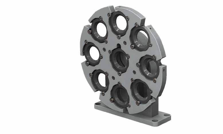

92 OPTO-MECHANICS Nanometer-Precision Opto-Mechanics
93 Copyright 2017 SmarAct GmbH Specifications are subject to change without notice. All rights reserved. Reproduction of images, tables or diagrams prohibited. The information given in this catalog was carefully checked by our team and is constantly updated. Nevertheless it is not possible to fully exclude the presence of errors. In order to always get the latest information, please contact our technical sales team. SmarAct GmbH, Schuette-Lanz-Straße 9, D Oldenburg Phone: +49 (0) , Telefax: +49 (0) Internet: 1
94
95 TABLE OF CONTENTS ABOUT OPTO-MECHANICS...4 SFW SID SID SID SID STT STT STT-25.4-CE...12 STT STT STT
96 OPTO-MECHANICS ABOUT OPTO-MECHANICS Nanometer Precision Opto-Mechanics For opto-mechanical setups SmarAct offers a variety of piezo driven components. With SmarAct s motorized iris diaphragms you can control remotely your optical setup. This is very useful for inaccessible setups, e.g. when working in an enclosed chamber or when automation is required. For automation our iris diaphragms can be equipped with optional micro- or nanosensors, providing a closed-loop control of the aperture. The aperture can be adapted to your application and we also offer vacuum compatible iris diaphragms. The STT positioners are motorized tip-tilt mirror mounts. They can be controlled by a manual remote control device via USB, Ethernet or RS232. The Tip-Tilt devices are available for 0.5, 1, 2 mirrors but other sizes and configurations can be made upon request. Our 1 mirror mounts are available with a high resolution position sensor. Motorized filter wheels are also available. If required by your application, special vacuum compatible versions can be made, too. 4

CU closed loop resolution 60 μ MCS Clodsed-Loop with -M sensor resolution 500μ")
97 OPTO-MECHANICS resolution rotation vacuum size SFW Motorized Filter Wheel < 1 μ 360 down to mbar 114 x 121 x 33 mm³ Mechanical Properties blocking force M B 5 Ncm positioner dimension 114 x 121 x 33 mm 3 weight 280 g Materials and Vacuum Options steel base (-ST), titanium base (-TI) non magnetic materials (-NM) higher blocking force (-D) -HV (10-6 mbar), -UHV / -UHVT (10-11 mbar) filter size: 0.5, 1, 1.5, 2 fully customizable Closed-Loop with -S sensor resolution 15 µ Closed-Loop with -L sensor resolution 60μ 1m (H)CU closed loop resolution 60 μ MCS Clodsed-Loop with -M sensor resolution 500μ closed loop resolution 1m (H)CU 500 μ MCS 9x n1" (Ø25.4mm) x n3.20 v n6.50 x n n113.8 Linear dimensions are given in mm and may change for different applications. 5

98 OPTO-MECHANICS SID-7 Motorized Iris Diaphragm aperture vacuum size 0.5 to 7 mm down to 10-6 mbar 60 x 55 x 13 mm 3 Mechanical Properties stainless spring steel positioner dimension 60 x 55 x 13 mm 3 minimum opening 0.5 mm maximum opening 7 mm weight 35 g number of leaves 12 Positioning step width nm opening resolution < 15 nm opening velocity 4 mm/s max. frequency 18.5 khz Materials and Vacuum Options black anodized (-BK) closed-loop on demand (-M)* 4 xm4 x focal plane Linear dimensions are given in mm and may change for different applications. 6 * positioner dimensions, mounting holes and travel range may vary and can be customized

99 OPTO-MECHANICS aperture vacuum size SID-18 Motorized Iris Diaphragm 1 to 18 mm down to 10-6 mbar 60 x 60 x 13 mm 3 Mechanical Properties stainless spring steel positioner dimension 60 x 60 x 13 mm 3 minimum opening 1 mm maximum opening 18 mm weight 35 g number of leaves 13 Positioning step width nm opening resolution < 30 nm opening velocity 6 mm/s max. frequency 18.5 khz Materials and Vacuum Options* black anodized (-BK) closed-loop on demand (-M) -HV (10-6 mbar, open-loop only) 4xM focal plane Linear dimensions are given in mm and may change for different applications. * positioner dimensions, mounting holes and travel range may vary and can be customized 7

100 OPTO-MECHANICS SID-50 Motorized Iris Diaphragm aperture vacuum size 5 to 50 mm down to 10-6 mbar 140 x 130 x 18 mm 3 Mechanical Properties stainless spring steel positioner dimension 140 x 130 x 18 mm 3 minimum opening 5 mm maximum opening 50 mm weight 60 g number of leaves 18 Positioning step width nm opening resolution < 30 nm opening velocity 6 mm/s max. frequency 18.5 khz Materials and Vacuum Options black anodized (-BK) closed-loop on demand (-M)* -HV (10-6 mbar, open loop only) 18 focal plane x n Linear dimensions are given in mm and may change for different applications. 8 * positioner dimensions, mounting holes and travel range may vary


101 OPTO-MECHANICS aperture vacuum non magnetic size SID-5714 Motorized Iris Diaphragm 0 to 25 mm down to 10-6 mbar available 57x57x19.9 mm 3 Mechanical Properties stainless spring steel positioner dimension 57 x 57 x 19.9 mm 3 weight 60 g Positioning step width nm scan resolution < 1 nm opening velocity 6 mm/s max. frequency 18.5 khz Materials and Vacuum Options black anodized (-BK) non magnetic materials (-NM) closed-loop on demand (-M) -HV (10-6 mbar, open-loop only) Iris Insert SID minimum aperture 1.2 mm maximum aperture 18 mm number of leaves 12 Iris Insert SID-0-22 minimum aperture fully closing maximum aperture 22 mm number of leaves 14 Iris Insert SID minimum aperture 1.5 mm maximum aperture 25 mm number of leaves 14 4x M3x0.5 x focal plane 30 n Linear dimensions are given in mm and may change for different applications. 9
 range Q ± 2.0 range F ± 2.")
 non magnetic materials (-NM) -HV (10-6 mbar), -UHV / -UHVT (10-11 mbar) M2 x2.")
102 OPTO-MECHANICS STT-12.7 Motorized Iris Diaphragm resolution rotation non magnetic vacuum size < 0.1 μrad F, Q: ± 2.0 available down to 10-6 mbar 20 x 20 x 10 mm³ Mechanical Properties mirror mount 12.7 mm (0.5 ) range Q ± 2.0 range F ± 2.0 thread for optical mount M2 positioner dimension 20 x 20 x 10 mm³ weight 20 g Positioning step width 2 μrad to 40 μrad scan range 40 μrad scan resolution < 0.1 μrad speed 15 /s max. frequency 18.5 khz Materials and Vacuum Options black anodized (-BK) non magnetic materials (-NM) -HV (10-6 mbar), -UHV / -UHVT (10-11 mbar) M2 x n Linear dimensions are given in mm and may change for different applications. 10
 range Q* ± 2.5 range F* ± 2.5 thread for optical mount M4 positioner dimension 35.6 x 35.6 x 12.")
103 OPTO-MECHANICS resolution rotation non magnetic vacuum size STT-25.4 Motorized Optical Mount < 0.1 μrad F, Q: ± 2.5 available down to mbar 35.6 x 35.6 x 12.3 mm³ Mechanical Properties mirror mount 25.4 mm (1 ) range Q* ± 2.5 range F* ± 2.5 thread for optical mount M4 positioner dimension 35.6 x 35.6 x 12.3 mm³ weight 25 g Positioning step width 2 μrad to 40 μrad scan range 40 μrad scan resolution < 0.1 μrad speed** 15 /s max. frequency 18.5 khz Materials and Vacuum Options black anodized (-BK) closed-loop on request only non magnetic materials (-NM) -HV (10-6 mbar), -UHV / -UHVT (10-11 mbar) Close Loop with inductive Sensor (-I) sensor resolution 1.4*10-3 accuracy ± 0.02 bidirectional position repeatability 0.01 M4 3,0 25,4 38,50 2,50 12,31 13,30 M4 3,0 38,50 19,80 19,80 35,60 38,50 2,50 38,50 Grey parts mark the optional position sensor. Linear dimensions are given in mm. * For close loop mirror mount +/ ** For close loop mirror mount 9 /s 11
104 OPTO-MECHANICS STT-25.4-CE Close-Loop Motorized Optical Mount in Clear Edge resolution rotation non magnetic vacuum size < 0.1 μrad F, Q: ± 2.5 available down to mbar 35.6 x 35.6 x 12.3 mm³ Mechanical Properties mirror mount 25.4 mm (1 ) range Q* ± 2.5 range F* ± 2.5 thread for optical mount M4 positioner dimension 38.5 x 38.5 x 13.3 mm³ weight 25 g Positioning step width 2 μrad to 40 μrad scan range 40 μrad scan resolution < 0.1 μrad speed** 15 /s max. frequency 18.5 khz Materials and Vacuum Options black anodized (-BK) closed-loop on request only non magnetic materials (-NM) -HV (10-6 mbar), -UHV / -UHVT (10-11 mbar) Close Loop with inductive Sensor (-I) sensor resolution 1.4*10^-3 accuracy ± 0.02 bidirectional position repeatability 0.01 M4 3,0 38,50 2,50 13,01 13,30 M4 3,0 38,50 19,80 25,4 19,80 38,50 35,60 2,50 38,50 Grey parts mark the optional position sensor. Linear dimensions are given in mm. 12 * For close loop mirror mount +/ ** For close loop mirror mount 9 /s
 range Q ± 1.0 range F ± 1.0 thread for optical mount M4 positioner dimension 60.5 x 60.5 x 18.")
 closed-loop on request only non magnetic materials (-NM) -HV (10-6 mbar), -UHV / -UHVT (10-11 mbar) M4 3,0 61 32,50")
105 OPTO-MECHANICS resolution rotation non magnetic vacuum size STT-50.8 Motorized Optical Mount < 0.1 μrad F, Q: ± 1.0 available down to mbar 60.5 x 60.5 x 18.3 mm³ Mechanical Properties mirror mount 50.8 mm (2 ) range Q ± 1.0 range F ± 1.0 thread for optical mount M4 positioner dimension 60.5 x 60.5 x 18.3 mm³ weight 30 g Positioning step width 2 μrad to 40 μrad scan range 40 μrad scan resolution < 0.1 μrad speed 15 /s max. frequency 18.5 khz Materials and Vacuum Options**** black anodized (-BK) closed-loop on request only non magnetic materials (-NM) -HV (10-6 mbar), -UHV / -UHVT (10-11 mbar) M4 3, ,50 4,50 Ø 50,80 32, ,50 18,30 M4 3,0 18,30 4,50 60,50 Linear dimensions are given in mm. 13

106 OPTO-MECHANICS STT-2013 Motorized Optical Mount resolution rotation non magnetic vacuum size < 2 μ F, Q: ± 90.0 available down to mbar 35 x x 60.7 mm³ Mechanical Properties range Q ± 90 range F ± 90 positioner dimension 35 x x 60.7 mm³ weight 30 g Positioning step width m scan range > 8 m scan resolution < 2 μ speed 45 /s max. frequency 18.5 khz 0.5 Mirror Mount maximum mirror size 12.7 mm 1.0 Mirror Mount maximum mirror size 25.4 mm Materials and Vacuum Options**** black anodized (-BK) steel base (-ST), titanium base (-TI) non magnetic materials (-NM) -HV (10-6 mbar), -UHV / -UHVT (10-11 mbar) Closed-Loop with Nanosensor (-S) sensor resolution 25 μ The STT-2013 consists of two SR-2013-S positioners and is able to provide full 360 in each DoF. It contains an exchangeable mirror mount for 0.5 to 1 mirrors and filters. This manipulator is available for ambient air, high vacuum and ultra high vacuum. The STT-2013 can also be delivered as an open-loop system. 45,70 Linear dimensions are given in mm. 14

107 OPTO-MECHANICS resolution rotation travel range vacuum size STT-50 Motorized Optical Mount < 0.2 μrad F, Q: ± mm down to mbar Ø 50 mm x 35 mm Mechanical Properties blocking torque M B max. normal force F N max. radial force F XY positioner dimension weight 2.1 Ncm 1.5 N 1.5 N 60.5 x 60.5 x 18.3 mm³ 120 g Positioning travel ± mm step width scan range scan resolution velocity μ rad nm 140 μ rad 1.3 μm < 0.1 μ rad < 1 nm 30 /s 10 mm/s Materials and Vacuum Options* -HV (10-6 mbar), -UHV / -UHVT (10-11 mbar) Closed-Loop with Nanosensor (-S) sensor resolution 0.1 μrad / 1 nm closed-loop resolution 0.2 μrad / 2 nm Closed-Loop with Microsensor (-M) sensor resolution 10 μ rad / 100 nm closed loop resolution (H)CU 50 μ rad / 300 nm MCS 10 μ rad / 100 nm x n2.1 6x M1.6 x3 n4 x A 1x M3 x3 Section A 4.95 n40 Linear dimensions are given in mm. * positioner dimensions, mounting holes and travel range may vary 15
108 16
109 About SmarAct SmarAct develops high-performance solutions for handling and positioning in the micro- and nanometer range. The broad product portfolio - from single positioners to complex parallel kinematics, miniaturized robots and easy-to-use control systems - is completed by sophisticated measuring equipment based on powerful laser interferometers. We serve high accuracy positioning and metrology applications in research and industry within such fields as optics, life sciences, micro-assembly, semiconductors and microscopy. Maintaining the complete production in house allows a high level of customization so that we can always provide you the optimal individual or OEM solution. HEADQUARTERS SmarAct GmbH Schuette-Lanz-Strasse Oldenburg Germany T: info-de@smaract.com USA SmarAct Inc Shattuck Ave., Suite 1103 Berkeley, CA United States of America T: info-us@smaract.com 07/2017

110 PARALLEL KINEMATICS Hexapodlike 6D parallel kinematics for ultra-precise applications
111 Copyright 2017 SmarAct GmbH Specifications are subject to change without notice. All rights reserved. Reproduction of images, tables or diagrams prohibited. The information given in this catalog was carefully checked by our team and is constantly updated. Nevertheless it is not possible to fully exclude the presence of errors. In order to always get the latest information, please contact our technical sales team. SmarAct GmbH, Schuette-Lanz-Straße 9, D Oldenburg Phone: +49 (0) , Telefax: +49 (0) Internet: 1
112
113 TABLE OF CONTENTS ABOUT SMARPOD...4 SMARPOD KEY FEATURES...4 SMARPOD MODELS...6 MODEL OVERVIEW...6 SMARPOD SMARPOD SMARPOD SMARPOD SMARPOD P-SLC SMARPOD P-SLC SMARPOD P-SLL...13 SMARPOD WAFER SMARPOD ACCESSORIES...15 SMARPOD CUSTOMIZATION
114 PARALLEL KINEMATICS ABOUT SMARPOD Parallel-Kinematics for Precise Applications Based on our linear positioners, we have developed parallel-kinematic systems for manipulating objects in all six degrees of freedom (three linear axes and three rotary axes), called SmarPod. The hexapod-like SmarPod is considerably more compact than common serial kinematics. It has many advantages such as higher rigidity, low moving mass hence improved dynamical response and a user-definable virtual pivot point. Due to the modular design of the SmarPod, its size and strength can be adapted to changing requirements, reaching from a few centimeters to almost a meter of travel with nanometer resolution. SMARPOD KEY FEATURES Six Degrees of Freedom The SmarPod is a parallel kinematics nanomanipulator. The stage is actuated by the simultaneous movement of multiple linear positioners, in contrast to a stacked (serial) design. The parallel arrangement of the positioners optimizes the overall system stiffness and allows to control all six degrees of freedom (X, Y, Z, roll, pitch and yaw). Control in Cartesian Coordinates Motion commands are expressed in Cartesian coordinates, and all transformations are encapsulated in the control libraries which gives you the possibility to issue commands from your own software, our graphical user interface or a SmarPod hand controller. User-Definable Pivot Point With the possibility to freely set the pivot point, it is easy to rotate around any point in space. Many Options Available High & ultra-high vacuum compatibility Non-magnetic material UV resilient materials Distance-coded reference marks for short referencing ways Black anodized for optical applications High Resolution and Repeatability A backlash-free mechanical design makes it possible to achieve a movement performance which is in the same order of magnitude as for our single positioners. The smallest movement increment is 1 nm for linear and 1 µrad for rotary motions. Over the whole travel the bidirectional repeatability is 200 nm in X, Y and Z and 10 µrad in roll, pitch and yaw. For smaller movements the repeatability is in the order of several nanometers as shown in the graphs on the next page. 4
![PARALLEL KINEMATICS SMARPOD KEY FEATURES Parallel-Kinematics for Precise Applications Linear Repeatability position [nm] time [s] Interferometer test 10 steps - back and forth Step width: 10 nm One](/docs-images/84/90580212/images/115-1.jpg "step every 200 ms Graph shows an excellent linear repeatability Angular Repeatability angle [µrad] time [s] Interferometer test 10 steps - back and forth Step width: 1 μrad One step every 500 ms")

115 PARALLEL KINEMATICS SMARPOD KEY FEATURES Parallel-Kinematics for Precise Applications Linear Repeatability position [nm] time [s] Interferometer test 10 steps - back and forth Step width: 10 nm One step every 200 ms Graph shows an excellent linear repeatability Angular Repeatability angle [µrad] time [s] Interferometer test 10 steps - back and forth Step width: 1 μrad One step every 500 ms Graph shows an excellent angular repeatability Linear Repeatability Test for 1 mm travel Interferometer test Travel range: 1 mm Standard deviation: 15 nm The figures show position data of a SmarPod during the cyclic linear displacement of 1 mm recorded with a laser interferometer. For illustration purposes the lower figure shows a zoom in the position range between -30 nm and 50 nm around the reference position. As it can be easily inferred from the figure, the reference position can be repeatedly reached with an accuracy of 15 nm (standard deviation). Therefore, the data show an excellent linear repeatability of the SmarPod. 5

116 PARALLEL KINEMATICS SMARPOD MODELS Parallel-Kinematics for Precise Applications SMARPOD NAMING The following examples show the dependencies between SmarPod naming and footprint for our standard circular SmarPods as well as the connection between name and movement range for our parallel SmarPods. Circular SmarPods SmarPod Diameter.Height Examples: SmarPod P-SLC x-axis SLC-1780, y-axis SLC 1750 (as shown below) SmarPod P-SLC x-axis SLC-24180, y-axis SLC 2475 SmarPod P-SLL x-axis SLL42-500, y-axis SLC-2475 Examples: SmarPod diameter 110 mm, height 45 mm Parallel SmarPods SmarPod P-Positioner-Series x-axis-length.y-axis-length MODEL OVERVIEW Product Line SmarPod Positioner Series P-SLC-17 P-SLC-24 P-SLL Wafer-200 max. vertical load [N] Mechanical max. horizontal load [N] dimension [mm 2 ] Ø 70 Ø 115 Ø 110 Ø 225 > 110 x 80 > 150 x 100 > 250 x x 430 height [mm] > 67.5 > 87 > weight [g] ,000 configuration dependent ,000 travel x [mm] Travel Ranges travel y [mm] travel z [mm] rotation x [ ] rotation y [ ] rotation z [ ] smallest increment [nm] Closed-Loop smallest increment [μrad] repeatability for [nm] < ± 200 < ± 200 < ± 200 < ± 200 < ± 200 < ± 200 < ± 200 < ± 200 full travel range [μrad] < ± 10 < ± 10 < ± 10 < ± 10 < ± 10 < ± 10 < ± 10 < ± 10 1mm linear travel [nm] < ± 15 < ± 15 < ± 15 < ± 15 < ± 15 < ± 15 < ± 15 < ± 15 sensor types -S, -SC -S, -SC -S, -SC -S, -SC -S, -SC -S, -SC -S, -SC -S, -SC vacuum compatibility HV, UHV HV, UHV HV, UHV HV, UHV HV, UHV HV, UHV HV HV 6
 available down to 10-11 mbar Ø 70 mm x 42 mm Mechanical Properties max. vertical load F V 5 N max. horizontal load F H 2.")
117 PARALLEL KINEMATICS resolution N normal load non magnetic vacuum size SMARPOD Parallel-Kinematics for Precise Applications < 1 nm 5 N (500 g) available down to mbar Ø 70 mm x 42 mm Mechanical Properties max. vertical load F V 5 N max. horizontal load F H 2.5 N positioner dimension Ø 70 x 42 mm³ weight 300 g Travel Ranges x 10 mm Q x 14 y 10 mm Q y 16 z 5 mm Q z 28 Materials and Vacuum Options** distance-coded sensor (-SC) non-magnetic materials (-NM) -HV (10-6 mbar), -UHV / -UHVT (10-11 mbar) smallest increment repeatability for full travel range* repeatability for 1 mm travel range* Closed-Loop with -S (x, y, z) 1 nm (Q x,y,z ) 1 μrad (x, y, z) ± 200 nm (Q x,y,z ) ± 10 μrad (x, y, z) ± 15 nm 3x n6.5 x5 n10.5 x3 3x n3.2 x5 n6.5 x n n70 SmaPod Linear dimensions are given in mm. * bidirectional for full travel range, unidirectional for 1 mm travel range ** positioner dimensions, mounting holes and travel range may vary 7

118 PARALLEL KINEMATICS SMARPOD Parallel-Kinematics for Precise Applications resolution N normal load non magnetic vacuum size < 1 nm 2.5 N (250 g) available down to mbar 115 x x 25 mm³ Mechanical Properties max. vertical load F V 2.5 N max. horizontal load F H 1.25 N positioner dimension 115 x x 25 mm³ weight 400 g Travel Ranges x 11 mm Q x 18 y 11 mm Q y 20 z 5 mm Q z 37 Materials and Vacuum Options** distance-coded sensor (-SC) non-magnetic materials (-NM) -HV (10-6 mbar), -UHV / -UHVT (10-11 mbar) smallest increment repeatability for full travel range* repeatability for 1 mm travel range* Closed-Loop with -S (x, y, z) 1 nm (Q x,y,z ) 1 μrad (x, y, z) ± 200 nm (Q x,y,z ) ± 10 μrad (x, y, z) ± 15 nm SmarPod Linear dimensions are given in mm. 8 * bidirectional for full travel range, unidirectional for 1 mm travel range ** positioner dimensions, mounting holes and travel range may vary
 available down to 10-11 mbar Ø 110 mm x 45 mm Mechanical Properties max. vertical load F V 5 N max. horizontal load F H 2.")
, -UHV / -UHVT (10-11 mbar) smallest increment repeatability for full travel range* repeatability for 1 mm travel range* Closed-Loop with -S (x, y, z) 1 nm (Q x,y,z ) 1 μrad (x, y, z)")
119 PARALLEL KINEMATICS resolution N normal load non magnetic vacuum size SMARPOD Parallel-Kinematics for Precise Applications < 1 nm 5 N (500 g) available down to mbar Ø 110 mm x 45 mm Mechanical Properties max. vertical load F V 5 N max. horizontal load F H 2.5 N positioner dimension Ø 110 x 45 mm³ weight 400 g Travel Ranges x 20 mm Q x 21 y 20 mm Q y 24 z 11 mm Q z 38 Materials and Vacuum Options** distance-coded sensor (-SC) non-magnetic materials (-NM) -HV (10-6 mbar), -UHV / -UHVT (10-11 mbar) smallest increment repeatability for full travel range* repeatability for 1 mm travel range* Closed-Loop with -S (x, y, z) 1 nm (Q x,y,z ) 1 μrad (x, y, z) ± 200 nm (Q x,y,z ) ± 10 μrad (x, y, z) ± 15 nm 3x n6.5 x5 n10.5 x n SmarPod Linear dimensions are given in mm. * bidirectional for full travel range, unidirectional for 1 mm travel range ** positioner dimensions, mounting holes and travel range may vary 9
 non magnetic available vacuum down to 10-11 mbar size Ø 225 mm x 75 mm Mechanical Properties* max.")
120 PARALLEL KINEMATICS SMARPOD Parallel-Kinematics for Precise Applications resolution < 1 nm N normal load 10 N (1000 g) non magnetic available vacuum down to mbar size Ø 225 mm x 75 mm Mechanical Properties* max. vertical load F V 10 N max. horizontal load F H 5 N positioner dimension ø 225 x 75 mm³ weight 1000 g Travel Ranges x 41 mm Q x 20 y 41 mm Q y 23 z 21 mm Q z 41 Materials and Vacuum Options** distance-coded sensor (-SC) non-magnetic materials (-NM) -HV (10-6 mbar), -UHV / -UHVT (10-11 mbar) smallest increment repeatability for full travel range* repeatability for 1 mm travel range* Closed-Loop with -S (x, y, z) 1 nm (Q x,y,z ) 1 μrad (x, y, z) ± 200 nm (Q x,y,z ) ± 10 μrad (x, y, z) ± 15 nm 3x n6.4 n11 x n SmarPod Linear dimensions are given in mm. 10 * bidirectional for full travel range, unidirectional for 1 mm travel range ** positioner dimensions, mounting holes and travel range may vary

 1 nm (Q x,y,z ) 1 μrad (x, y, z) ± 200 nm (Q x,y,z ) ± 10 μrad (x, y, z) ± 15 nm SmarPod P-SLC-17 80.50.")
121 PARALLEL KINEMATICS resolution N normal load non magnetic vacuum size SMARPOD P-SLC-17 Parallel-Kinematics for Precise Applications < 1 nm 5 N (500 g) available down to mbar 110 x 80 x 67.5 mm³ Mechanical Properties* max. vertical load F V 5 N max. horizontal load F H 2.5 N positioner dimension > 110 x 80 x 67.5 mm³ weight g Travel Ranges x 48 mm Q x 28 y mm Q y 26 z 9 mm Q z 20 Materials and Vacuum Options*** distance-coded sensor (-SC) non-magnetic materials (-NM) -HV (10-6 mbar), -UHV / -UHVT (10-11 mbar) smallest increment repeatability for full travel range** repeatability for 1 mm travel range** Closed-Loop with -S (x, y, z) 1 nm (Q x,y,z ) 1 μrad (x, y, z) ± 200 nm (Q x,y,z ) ± 10 μrad (x, y, z) ± 15 nm SmarPod P-SLC Linear dimensions are given in mm. * positioner dimension, weight and travel strongly depending on SmarPod configuration ** bidirectional for full travel range, unidirectional for 1 mm travel range *** positioner dimensions, mounting holes and travel range may vary 11

 1 nm (Q x,y,z ) 1 μrad (x, y, z) ± 200 nm (Q x,y,z ) ± 10 μrad (x, y, z) ± 15 nm 64 4 x 6.4 11 6.")
122 PARALLEL KINEMATICS SMARPOD P-SLC-24 Parallel-Kinematics for Precise Applications resolution < 1 nm N normal load 10 N (1000 g) non magnetic available vacuum down to mbar size > 150 x 100 x 87 mm³ Mechanical Properties* max. vertical load F V 10 N max. horizontal load F H 5 N positioner dimension > 150 x 100 x 87 mm³ weight g Travel Ranges x mm Q x 31 y mm Q y 27 z 12 mm Q z 42 Materials and Vacuum Options*** distance-coded sensor (-SC) non-magnetic materials (-NM) -HV (10-6 mbar), -UHV / -UHVT (10-11 mbar) smallest increment repeatability for full travel range** repeatability for 1 mm travel range** Closed-Loop with -S (x, y, z) 1 nm (Q x,y,z ) 1 μrad (x, y, z) ± 200 nm (Q x,y,z ) ± 10 μrad (x, y, z) ± 15 nm 64 4 x SmarPod P-SLC Linear dimensions are given in mm. 12 * positioner dimension, weight and travel strongly depending on SmarPod configuration ** bidirectional for full travel range, unidirectional for 1 mm travel range *** positioner dimensions, mounting holes and travel range may vary

 ± 200 nm (Q x,y,z ) ± 10 μrad (x, y, z) ± 15 nm SmarPod P-SLL 500.75.3 Linear dimensions are given in mm.")
123 PARALLEL KINEMATICS resolution < 1 nm N normal load 10 N (1000 g) vacuum down to 10-6 mbar size > 250 x 93 x 67.5 mm³ SMARPOD P-SLL Parallel-Kinematics for Precise Applications max. vertical load F V max. horizontal load F H positioner dimension weight Mechanical Properties* 10 N 5 N > 250 x 93 x 67.5 mm³ g Travel Ranges x mm Q x 42 y mm Q y 33 z 16 mm Q z 42 Materials and Vacuum Options*** distance-coded sensor (-SC) -HV (10-6 mbar) Closed-Loop with -S smallest increment (x, y, z) 1 nm (Q x,y,z ) 1 μrad repeatability for full travel range** repeatability for 1 mm travel range** (x, y, z) ± 200 nm (Q x,y,z ) ± 10 μrad (x, y, z) ± 15 nm SmarPod P-SLL Linear dimensions are given in mm. * positioner dimension, weight and travel strongly depending on SmarPod configuration ** bidirectional for full travel range, unidirectional for 1 mm travel range *** positioner dimensions, mounting holes and travel range may vary 13

124 PARALLEL KINEMATICS SMARPOD WAFER-200 Parallel-Kinematics for Precise Applications resolution < 1 nm N normal load 20 N (2000 g) non magnetic available vacuum down to 10-6 mbar size > 420 x 430 x 93 mm³ Mechanical Properties max. vertical load F V 20 N positioner dimension 420 x 430 x 93 mm³ weight 11 kg Travel Ranges x 200 mm Q x 6 y 200 mm Q y 7 z 10 mm Q z 24 Materials and Vacuum Options** distance-coded sensor (-SC) -HV (10-6 mbar) smallest increment repeatability for full travel range* repeatability for 1 mm travel range* Closed-Loop with -S (x, y, z) 1 nm (Q x,y,z ) 1 μrad (x, y, z) ± 200 nm (Q x,y,z ) ± 10 μrad (x, y, z) ± 15 nm 6x n6.4 n11 x SmarPod Wafer Linear dimensions are given in mm. 14 * bidirectional for full travel range, unidirectional for 1 mm travel range ** positioner dimensions, mounting holes and travel range may vary

 SMARPOD CUSTOMIZATION Exemplary Features for your Application")


125 PARALLEL KINEMATICS SMARPOD ACCESSORIES Parallel-Kinematics for Precise Applications SmarPod Hand Controller Manual control of the SmarPod One knob per direction or rotation Store & recall poses for defined positions Speed and step-size adjustment Simple pivot-point adjustment Embedded Control Module (ECM) Stand-alone control with embedded kinematic calculations (for multiple SmarPods) Network and serial communication interfaces ASCII based command language easy integration into existing control environments (e.g. EPICS, TANGO) SMARPOD CUSTOMIZATION Exemplary Features for your Application Anodization for Optical Applications Non-reflective surfaces Hard and robust surfaces Electrical insulated surfaces Different colors available SmarPods for Micro-Assembly Combination with micro-grippers Precise handling and alignment of optical components Integrated sensors for closed-loop control Synchrotron Applications Non-magnetic materials Compatibility for high and ultra-high vacuum Integrated sensors for closed-loop control UV resilient materials Customized Designs for SEM Applications Non-magnetic materials Insulated top plate for separate ground potential Compatibility for high and ultra-high vacuum 15
126 16
127 About SmarAct SmarAct develops high-performance solutions for handling and positioning in the micro- and nanometer range. The broad product portfolio - from single positioners to complex parallel kinematics, miniaturized robots and easy-to-use control systems - is completed by sophisticated measuring equipment based on powerful laser interferometers. We serve high accuracy positioning and metrology applications in research and industry within such fields as optics, life sciences, micro-assembly, semiconductors and microscopy. Maintaining the complete production in house allows a high level of customization so that we can always provide you the optimal individual or OEM solution. HEADQUARTERS SmarAct GmbH Schuette-Lanz-Strasse Oldenburg Germany T: info-de@smaract.com USA SmarAct Inc Shattuck Ave., Suite 1103 Berkeley, CA United States of America T: info-us@smaract.com 07/2017

128 SmarAct CONTROLLER AND SOFTWARE Versatile Control for Micro- and Nanopositioning
129 Copyright 2017 SmarAct GmbH Specifications are subject to change without notice. All rights reserved. Reproduction of images, tables or diagrams prohibited. The information given in this catalog was carefully checked by our team and is constantly updated. Nevertheless it is not possible to fully exclude the presence of errors. In order to always get the latest information, please contact our technical sales team. SmarAct GmbH, Schuette-Lanz-Straße 9, D Oldenburg Phone: +49 (0) , Telefax: +49 (0) Internet: 1
130
131 TABLE OF CONTENTS CONTROL SYSTEMS...4 HCU-1D, CU-1D...5 HCU-3C...6 CU-3C...7 MODULAR CONTROL SYSTEM...8 DRIVER MODULES...8 SENSOR MODULES...8 MCS...9 MCS MCS SENSOR MODULE...11 SENSOR READER...11 MCS HAND CONTROLLER...12 SMARPOD AND UNIVERSAL HAND CONTROLLER...12 EMBEDDED CONTROL MODULE...13 ANALOG VOLTAGE CONTROL...13 EMBEDDED MICROSENSOR SYSTEM (EMS 2D/ EMS 3D)...14 SDC / SDC SMARACT SOFTWARE...16 PRECISION TOOL COMMANDER...16 KEY FEATURES...17 SCANNING...17 AUTOMATIC ALIGNMENT...17 AUTOMATED FIBER ALIGNMENT SETUP...18 SMARPOD CONTROL SOFTWARE
132 CONTROL SYSTEMS CONTROL SYSTEMS Micro- and Nanopositioning Made Simple We offer several lines of control systems. The Simple Control Units (SCU) are stand-alone devices for small micropositioning systems. They can control positioning systems with sensor feedback (-M, -L, closed-loop) and without sensor feedback (open-loop). There are two versions available - the HCU with integrated hand control unit and the CU as OEM or table top unit. The Modular Control System (MCS) is a more advanced control system and it is the perfect choice for all positioning tasks up to sub-nm resolution. It is capable of controlling large positioning systems with up to n x 3 positioners with sensor feedback (-M, -L, -S) or without sensor feedback. The controller lines SCU and MCS come with a USB or Ethernet interface. A basic stand-alone control program, a Windows Dynamic Link Library (DLL), LabVIEW driver and Linux drivers are part of the included software package. Alternatively, an RS232 or Ethernet ASCII interface is available to communicate with the controllers via simple ASCII commands. The Step-Direction Controller (SDC) is a low-level control system which allows to move Smar- Act s positioners in a stepper motor like manner but with a very high resolution. Therefore, only two TTL signals are required in order to define number of steps and direction. Furthermore, the SDC2 control unit provides a quadrature signal feedback. With the Analog Voltage Control (AVC) SmarAct positioners can be controlled by an analog voltage between -10V and 10V which defines the speed and direction of the movement. The Embedded Microsensor System (EMS 2D/3D) provides an optimized OEM control unit for integration into your own control units. With the EMS it is possible to control axes with inductive sensors (-I). All our control units are customizable upon request in order to match your specific application requirements (e.g. OEM solutions). 4

133 CONTROL SYSTEMS control control channels sensor type HCU-1D, CU-1D Micropositioning Made Simple closed-loop 1 micro The CU-1D and HCU-1D are simple devices for controlling any SmarAct open-loop positioner with sub- µm resolution. The HCU-1D has a single knob and a USB interface so that you can immediately start using your positioner after connecting it. The LED array-display shows the selected speed level. The CU-1DM/1CL and HCU-1DM/1CL enable you to control closed-loop positioners with integrated -M or -L sensor. For remote control you can use SmarAct s standalone control-program or develop your own software application by using SmarAct s Dynamic Link Library or LabVIEW driver. Operation Mode channels 1 feedback loop sensor support -M, -L optional hand control (HCU) voltage range maximum output current positioner interface PC interface power supply scalability housing software / drivers data cable AC adapter Output Signals open-loop, closed-loop module with control knobs and LED array V 170 ma Interfaces 1 x DSUB 15, female USB 12 V, 24 W Integration of Controller Accessories 1-channel board table-top (-TAB), single control board (-OEM) Windows (version 7 and higher) Driver, LabVIEW Driver 1.5 m USB cable V, Hz 5
134 CONTROL SYSTEMS HCU-3C Micropositioning Made Simple control control channels sensor type closed-loop 3 micro The HCU-3C controller is a stand-alone device to control up to three SmarAct positioners. It has three control knobs, a joystick and a display which allows you to define several important driving parameters. The HCU-3CX/L/M enables you to control closedloop positioners with integrated M, -L or I-sensor. For remote control you can use SmarAct s standalone control-program or develop your own software application with SmarAct s Dynamic Link Library or LabVIEW drivers. Operation Mode channels 3 feedback loop sensor support -M, -L, -I hand control (HCU) voltage range maximum output current positioner interface PC interface power supply scalability housing software / drivers data cable AC adapter Output Signals Interfaces open-loop, closed-loop module with control knobs, joystick and LED display V 360 ma / channel 1 x DSUB 15 (-CL/M), 1x DSUB 26HD (-CX) USB, RS V, 48 W Integration of Controller Accessories 3-channel board table-top (-TAB), single control board (-OEM) Windows (version 7 and higher) Driver, LabVIEW Driver, for RS232 documentation only 1.5 m USB / RS232 cable V, Hz 6
. The CU-3C controller is equipped either with USB or RS232 interface.")

135 CONTROL SYSTEMS control control channels sensor type CU-3C Micropositioning Made Simple closed-loop 1 micro The CU-3C controller is a single board version of the HCU-3C controller. It can be provided with or without housing, thus, it is ideal for original equipment manufacturers (OEM). The CU-3C controller is equipped either with USB or RS232 interface. It enables you to control connected positioners with SmarAct s stand-alone control-program or your own developed software based on SmarAct s Dynamic Link Library or LabVIEW driver. The CU-3CX/L/M enables you to control closed-loop positioners with integrated -M, -L or -I sensor. Operation Mode channels 3 feedback loop sensor support -M, -L, -I voltage range maximum output current positioner interface PC interface power supply scalability housing software / drivers data cable AC adapter Output Signals Interfaces open-loop, closed-loop V 360 ma / channel 1 x DSUB 15 (-CL/M), 1x DSUB 26HD (-CX) USB, RS V, 48 W Integration of Controller Accessories 3-channel board table-top (-TAB), single control board (-OEM) Windows (version 7 and higher) Driver, LabVIEW Driver, for RS232 documentation only 1.5 m USB / RS232 cable V, Hz 7

136 CONTROL SYSTEMS MODULAR CONTROL SYSTEM Scalable Micro- and Nanopositioning Control The Modular Control System (MCS) is suitable for both micro- and nanopositioning tasks. Thanks to the modular concept we can assemble control systems with the number of channels matching the connected positioning systems. Accordingly, you can combine multiple driver modules and control them via the same computer-interface. with Windows DLL, LabVIEW driver and simple control program. If you prefer ASCII commands, you can choose between Ethernet- or RS-232-interface. Furthermore, you can control connected positioning systems manually when adding a hand-controller module to the MCS. Attaching a sensor-module allows you to control our positioners in closed-loop mode. It can connect up to three positioners to one driver module and is available for the three sensor-types -S, -L and -M. The MCS is also available as a 19 -rack mount chassis-module or as a naked board for OEM products. Three different computer interfaces are available: USB, Ethernet and RS-232. In case of USB and Ethernet, we deliver the controller DRIVER MODULES Each MCS controller contains driver modules and / or end effector modules to control different positioners and/or end- effectors. Each driver module can control up to three positioners. Therefore, MCS controllers with three, six, nine, etc. control channels are available. A driver module creates the necessary signals for driving the connected positioners in step- and scan-mode. Additionally, the driver module processes and controls the measured position (closed-loop control) when a closed-loop positioner is connected via a sensormodule. SENSOR MODULES MCS-3CC-3H-USB-TAB MCS three channel control system with integrated hand-control module for manual positioning. If you want to use closed-loop positioners with integrated nano- or microposition sensors an external sensor-module is necessary which digitizes the sensor data. The MCS driver module calculates and controls the current position based on the sensor signals. There are many different sensor-module options available: MCS-nM/L/S-.. for n positioners with integrated -M, -L or -S sensor MCS-..-TAB for table top housing (see image below) MCS-..-LEMO for housing with Lemo connectors MCS-..-OEM for integration into system baseplates MCS-3S-EP-SDS15-TAB MCS sensor module for a three channel control system. 8

 1 x DSUB 15, female USB, RS232, Ethernet Integration of Controller Accessories 12 V, 30 W (1 channel); 12-24 V, 60 W (3.")
137 CONTROL SYSTEMS control control channels sensor type MCS Scalable Micro- and Nanopositioning Control open-loop, closed-loop 1, 3, n x 3 micro, nano Operation Mode channels 1, 3, n x 3 feedback loop sensor support -M, -L, -S optional hand control voltage range maximum output current positioner interface PC interface power supply scalability housing software / drivers data cable AC adapter Output Signals Interfaces open-loop, closed-loop module with control knobs and LED display V 360 ma / channel (C), with booster 1.08 A / channel (B) 1 x DSUB 15, female USB, RS232, Ethernet Integration of Controller Accessories 12 V, 30 W (1 channel); V, 60 W (3.. 6 channels), with booster 180 W (3 channels) stackable 3-channel board table-top (-TAB), single control board (-OEM), 19 rack mount chassis module (-MOD) Windows software, Windows driver (version 7 and higher), Linux library, LabVIEW driver, for ASCII documentation only 1.5 m USB / RS232 cable V, Hz The MCS driver modules are available with different housing and interface options. For example, the MCS-3CC-USB-MOD (right) is a compact controller for up to three positioners which can be mounted in a 19 rack chassis. The MCS-3CC- ETH-TAB on the left has an Ethernet-interface and a compact table-top housing. In both cases an external hand-controller module can be added which allows convenient manual operation (p. 12). 9


138 CONTROL SYSTEMS MCS2 Modular Control System control control channels sensor type open-loop, closed-loop n x 3, max. 18 channels micro, nano Channels Control modes Supported sensors Interface Voltage range Frequency Output connectors Operation Mode Output Signals n x 3, max. 18 channels open-loop and closed-loop -S, -M, -L, PicoScale interferometer USB 2.0 or Ethernet V 0 20 khz D-SUB 15, female Scalability Housing options Software / Drivers Data cable Power supply Integration of Controller Accessories stackable 3-channel board tabletop, 19 rack, single control board (OEM) Windows driver (7 or higher), Linux drivers, LabVIEW 1.5 m USB 12 V AC/DC adapter The MCS2 belongs to the family of Modular Control Systems and is SmarAct s most powerful control system. The follow-up model of the MCS is a compact motion controller and suitable for high-resolution positioning applications from the meter down to the picometer scale. Following the modular design of the MCS product family, multiple positioners can be driven at the same time via a PC interface or a hand control unit. Whether you would like to simply control a single axis or a complex multi-axes system the MCS2 will be the right choice. The implemented streaming mode enables synchronized control of multiple positioners moving on complex trajectories. Additionally, the device offers software-tunable input and output trigger options. Its advanced Quiet Mode for working with reduced noise emission qualifies the MCS2 particularly for life science applications. Furthermore, the MCS2 is available in different housing options. 10


139 CONTROL SYSTEMS MCS SENSOR MODULE control closed-loop control channels 1, 2, 3 sensor type micro, nano Various housing and connector-options are available for the MCS sensor-module. Depending on your application we can use a simple adapter box with DSUB-connectors or mount the sensor module directly to vacuum feedthroughs. In addition, as an OEM-version, it can be directly integrated into baseplates of positioning and handling systems. SENSOR READER control closed-loop control channels 1, 2, 3 sensor type nano For high position data bandwidths the Sensor Reader is an ideal extension for SmarAct control systems like MCS or SDC. When connected to an MCS/SDC, the Sensor Reader extracts the raw data stream of the sensor module and provides position data with a bandwidth of up to 8kHz. Using the USB interface of the Sensor Reader the data is accessible via DLL or LabVIEW libraries. The Sensor Reader allows for additional capturing of up to three analog signals, enabling synchronization of position data with any external electrical signal. Properties standard cable length 1.5 m (max. 15 m) -S sensor -L sensor -M sensor analog inputs DSUB15 socket LEMO 1B plug LEMO 2B plug OEM board table-top housing table-top housing with mounting holes plug on cable socket Sensor Type one (-1S), two (-2S) or three (-3S) channels one (-1L), two (-2L) or three (-3L) channels one (-1M), two (-2M) or three (-3M) channels three additional analog input channels (-3ADC) Positioner Connector Type -SDS15 -LEMO1B -LEMO2B Integration of Controller -OEM -TAB -TABM -EP -ES 11


140 CONTROL SYSTEMS MCS HAND CONTROLLER Scalable Micro- and Nanopositioning Control The external hand-controller module can be connected to any MCS driver module. It allows ease of use of SmarAct positioning systems utilizing joysticks and control knobs. The hand-controller module is available either as a three channel or multi-channel device. Operation Mode controller type MCS-3H MCS-NH channels 3 unlimited operating elements 2 joysticks 3 knobs 2 joysticks 4 knobs SmarPod AND UNIVERSAL HAND CONTROLLER Scalable Micro- and Nanopositioning Human Interface Device The SmarPod Hand Controller makes it possible to control the SmarPod as well as any other SmarAct motion system in a convenient and easy way in all six degrees of freedom. Beside different speed levels and step sizes, it offers four quick save buttons to store and recall eight poses of the SmarPod or SmarAct positoners. The controller can be connected to a USB port of the computer. By using LabVIEW or the provided C programming library you can define the function of the buttons, rotary knobs and programmable LEDs. The detailed documentation allows a simple commissioning of the Human Interface Device. When using this controller with SmarAct s SmarPods, the hand module support is completely handled by the SmarPod Software and no further implemenation is necessary. compatible positioners control elements Operation Mode interface USB 2.0 software all SmarPod models, all SmarAct positioners and manipulators 6 knobs for Cartesian coordinates 2 speed level buttons 4 double assigned quicksave buttons mode button emergency stop C / LabVIEW SDK, SmarPod controller 12
 without the need of an additional PC. The ECM performs the kinematic calculations and works as a command interpreter for SmarPods and SmarAct positioners connected to MCS controllers.")

141 CONTROL SYSTEMS EMBEDDED CONTROL MODULE The Embedded Controller Module (ECM) offers an easy integration of SmarPods into existing control environments (e.g. EPICS, TANGO, etc.) without the need of an additional PC. The ECM performs the kinematic calculations and works as a command interpreter for SmarPods and SmarAct positioners connected to MCS controllers. No driver software is needed on the client side. Commands can be sent in an ASCII-based control language. Clients can connect to an ECM via Ethernet or RS232 serial cable. The ECM control unit is available as a rack module for SmarAct 19 racks or as a table-top device, both with an integrated LCD display. Due to its flexible software it is possible to adapt the system to customer requirements. interfaces controller compatibility housing Operation Mode RS232, Ethernet, USB all SmarAct MCS controllers 19 rack mount chassis (-MOD), table-top (-TAB) ANALOG VOLTAGE CONTROL The AVC is a low-level controller, which enables you to build your own external closed-loop control system with high resolution for SmarAct positioners by utilizing a suitable feedback signal. Thus, a computer is not needed which allows an easy integration into your products for different applications, such as beam stabilization. Properties compatible positioners power supply input signals for frequency and direction input signal for step size dimensions all SmarAct positioners with stick-slip drives V, 24W backward k -10 V.. 1 m -1 V no movement between -1 V.. 1 V forward - 1 m 1 V k 10 V V V 100 x 60 mm 2 OEM board 13


142 CONTROL SYSTEMS EMBEDDED MICROSENSOR SYSTEM (EMS 2D/ EMS 3D) Scalable Micro- and Nanopositioning Control The Embedded Microsensor System (EMS; 2D for two channels and 3D for three channels) are SmarAct s smallest control boards, perfectly suited for integration into your own control systems. The extremely small footprint 2D: 58 x 32 mm²; 3D: 76 x 60 mm² makes it the best choice to control closed-loop positioners with -I or -L sensors for OEM systems. The EMS is currently available in two different configurations to control two or three axes. Properties compatible positioners channels power supply positioner interface PC interface scalability voltage range, max. current dimensions all SmarAct positioners with Stick-Slip drives (60V), -I and -L sensors supported 2 for 2D, 3 for 3D (one channel controllable at a time) 2D: 5-12 V / V, 15W; 3D: 12-24V, 15W 2D: Micromatch; 3D: DSUB 25, female two wire interface (TWI) maximum 8 via TWI (depending on connected PC) V, 250 ma 2D: 58 x 32 mm 2 ; 3D: 76 x 60 mm 2 14


 Interfaces The SDC2 reads-in step-direction signals (1) from a stepper motor")

143 CONTROL SYSTEMS control control channels sensor type SDC / SDC2 Scalable Micro- and Nanopositioning Control closed-loop n x 1 micro, nano With the SDC and SDC2 we offer a low level control system to use SmarAct positioners like stepper motors. The standard inputs of the SDC controller are step and direction signals. So you can profit from the performance of our positioners with only minor changes to your own established control structure. For every step a closed-loop controlled position increment is performed in the specified direction. In order to get position data, the SDC2 supports quadrature signal feedback. Operation Mode channels n x 1 feedback loop open-loop, closed-loop sensor support -M, -L, -S Output Signals voltage range V maximum output current position feedback 360 ma / channel square shape signal, quadrature feedback (SDC2) Interfaces The SDC2 reads-in step-direction signals (1) from a stepper motor controller and then generates signals that drive the positioners. The position change in the positioner then leads to a sinus / cosinus signal of the integrated optical sensor (2). This signal is then digitized and transmitted with a serial RS485 data stream to the SDC2 controller. Based on this position feedback the SDC2 controller performs closed-loop position control and outputs quadrature signals (3). positioner interface PC interface power supply interface board scalability housing software / drivers data cable AC adapter 1 x DSUB 15, female STEP / DIR 5 V TTL or open collector RS232 for configuration V, 60 W (with 19 rack up to 600W) Integration of Controller euro-sized board with DSUB9 for CLK / DIR (-EUR) MAXV controller board with SCSI connector (-MAX) single channel board, adapter board for two SDC boards table-top (-TAB), single control board (-OEM), 19 rack module (-MOD) Accessories SDC configuration program for Windows 1.5 m RS232 cable V, Hz together with table-top unit 15


 is a graphical user interface for controlling SmarAct positioning systems.")
144 CONTROL SYSTEMS SMARACT SOFTWARE Motion Control Made Easy Our MCS controllers are bundled with software tools, such as the Precision Tool Commander and several other powerful programming interfaces. Precision Tool Commander Graphical software for controlling single positioners or positioning systems. MCS Configuration Tool Simple user interface to configure settings of all types of MCS controllers. SmarPod Control Software Simple user interface to configure settings of all types of SmarPod systems. Programming Programming interfaces for all SmarAct products. C/C++ interface (Windows, Linux, compatible with other programming languages) and Lab- VIEW APIs are supported. Functions for full control of all SmarPod models. PRECISION TOOL COMMANDER Powerful Control Software Precision Tool Commander (PTC) is a graphical user interface for controlling SmarAct positioning systems. It is free for all SmarAct customers. Positioners can be moved with a computer mouse or by entering positions with the keyboard. 16


145 CONTROL SYSTEMS SMARACT SOFTWARE Motion Control Made Easy KEY FEATURES The PTC2 supports MCS and SmarPod positioning systems. All MCS can be controlled in open-loop, closed-loop and piezo-scan mode. Multiple positioning systems can be used simultaneously. The PTC2 can be configured to match the users hardware setup. Configurations can be switched quickly. Measuring equipment can be integrated through software plug-ins. Support for new measuring hardware like power meters can be developed upon request. SCANNING PTC2 can record data from any connected sensor while scanning a 1D or 2D area. Measured data can be exported as image or CSV files. AUTOMATIC ALIGNMENT An advanced tool for aligning with up to six positioners simultaneously is integrated into the PTC2 as well. It uses an iterative algorithm to find the optimum configuration of the chosen parameters. Any supported sensor can be used as an indicator for alignment progress. Typical applications: fiber coupling, beam-profiling, quality assurance and assistance for part assembly. 17


146 CONTROL SYSTEMS SMARACT SOFTWARE Motion Control Made Easy AUTOMATED FIBER ALIGNMENT SETUP The fibers (left image) are coupled with scan and auto alignment features of the PTC2. Any DoF can be used for the auto alignment. In case of the SmarPod configuration (right image) x and z position as well as tip and tilt are adjusted for an optimum result. SMARPOD CONTROL SOFTWARE Intuitive SmarPod Control The SmarPod Control Software is a graphical user interface, which can control all current SmarPod models. Main Features of the SmarPod Control Software Simple control of SmarPods. Handles multiple SmarPod configurations. Stores and recalls up to 10 SmarPod poses. Moves SmarPods with a 6D mouse or the Smar- Pod hand controller. Convenient adjustment of pivot point with the hand controller. 18
147 19
148 20
149 About SmarAct SmarAct develops high-performance solutions for handling and positioning in the micro- and nanometer range. The broad product portfolio - from single positioners to complex parallel kinematics, miniaturized robots and easy-to-use control systems - is completed by sophisticated measuring equipment based on powerful laser interferometers. We serve high accuracy positioning and metrology applications in research and industry within such fields as optics, life sciences, micro-assembly, semiconductors and microscopy. Maintaining the complete production in house allows a high level of customization so that we can always provide you the optimal individual or OEM solution. HEADQUARTERS SmarAct GmbH Schuette-Lanz-Strasse Oldenburg Germany T: info-de@smaract.com USA SmarAct Inc Shattuck Ave., Suite 1103 Berkeley, CA United States of America T: info-us@smaract.com 07/2017

150 PICOSCALE Interferometric displacement sensor with picometer resolution
151 Copyright 2017 SmarAct GmbH Specifications are subject to change without notice. All rights reserved. Reproduction of images, tables or diagrams prohibited. The information given in this catalog was carefully checked by our team and is constantly updated. Nevertheless it is not possible to fully exclude the presence of errors. In order to always get the latest information, please contact our technical sales team. SmarAct GmbH, Schuette-Lanz-Straße 9, D Oldenburg Phone: +49 (0) , Telefax: +49 (0) Internet: 1
152
153 TABLE OF CONTENTS PICOSCALE BASICS...4 Working principle...6 Benefits of the PICOSCALE...7 INTERFACES...8 Digital Differential Interface...9 USB and Ethernet...9 SENSOR HEADS...10 Sensor head selection guide...11 Sensor head type C SmarAlign window and integrated pilot laser...13 Options for C01 head type...13 Sensor head type C Sensor head type C Sensor head type F Sensor head type L Sensor head assemblies...18 FIRMWARE MODULES...20 Advanced Trigger...21 Calculation System...22 Signal Generator...23 Stream Generator...24 Clock Generator...25 Counter...26 SOFTWARE...28 PICOSCALE CONTROL...28 API AND DLLS...33 ACCESSORIES...34 Breakout-Box...35 Environmental Module...36 MCS Sensor head mounting options...38 Kinematic mirror mounts...39 Additional optical components...40 APPLICATION EXAMPLES...41 Position stability measurements...42 Measurements on various surfaces...43 Differential measurements...44 Radial run-out measurement...45 Scanning interferometer...46 Angular measurements...47 CLOSING REMARKS...48 Loan service and customization

154 BASICS PICOSCALE Interferometric displacement sensor with picometer resolution Powerful firmware modules: Advanced Trigger module Real-time Calculation System Signal Generator Clock Generator Counter Michelson interferometer: Low restrictions on target reflectivity External reference mirror possible for true differential measurements Fast and user-friendly alignment and system configuration: Integrated pilot laser Convenient graphical user interface Useful accessory: Breakout-Box for easy access to GPIO interface Environmental Module Mounting options...and many more Direct and flexible customer support: Intensive consulting by our technical sales engineers Customization of hardware, software and applications 4

155 BASICS PICOSCALE Interferometric displacement sensor with picometer resolution Various sensor heads: Collimated probe beam Focused probe beam Electronic free design Low head dissipation Customized solutions Interfaces: USB Ethernet AquadB Serial Data Easy integration into existing periphery: Advanced Trigger system for synchronization of devices Direct interface for SmarAct s MCS2 motion controller Standard and customized solutions for mechanical integration Applications: Displacement measurements Angular measurements Vibrometry Closed-loop positioning...and many more PICOSCALE The PICOSCALE is a powerful system for optical and non-invasive displacement and vibration measurements. The three channel device offers several interfaces and flexible software modules. Useful accessories and a high degree of customization make it easy to efficiently integrate the PICOSCALE in your measurements. The graphical user interface allows for very user friendly operation and features versatile data visualization. In summary, these characteristics make the PICOSCALE a very powerful tool! Key features Resolution 1 pm Number of channels 3 Working distance mm Max. velocity 1 m/s Data rate up to 10 MHz Laser 1550 nm, 150 µw 5
156 BASICS PICOSCALE Working principle and key facts Reference mirror Target mirror PICOSCALE Beam splitter (in sensor head) Working distance The PICOSCALE is based on a Michelson interferometer consisting of a wavelength-stabilized laser, a beam splitter, a target and a reference mirror. Typically, the reference mirror is directly coated to one surface of the beam splitter which is built into the PICOSCALE sensor heads. The light is divided into two parts which are reflected at the reference and target mirror. After recombination in the beam splitter, the interference signal contains information on the displacement of the target mirror. Property Number of channels 3 Resolution Working distance Maximum target velocity Value 1 pm mm (depending on sensor head) Possible targets Retro-reflector, mirror, target reflectivity 4-100% Measurement laser Pilot laser Measurement conditions Environmental compensation Interfaces Data rate GPIO interface Software control Controller chassis Firmware modules Order Code 1 m/s 1550 nm, Laser class 1; stabilized (NIST traceable) 650 nm, Laser class 1 Ambient, high vacuum, ultra-high vacuum, cryogenic Possible with Environmental Module USB, Ethernet AquadB, Serial Data up to 10 MHz 9 x Digital in-/output 5 x Analog output 3 x Analog input Graphical user interface PICOSCALE Control C and LabVIEW drivers Software API and DLLs 33 x 27 x 7.3 cm³, weight 3.5 kg (table top version) 48.2 x 31 x 4.5 cm³, weight 3.8 kg (19 rack version) Advanced trigger (for convenient synchronization, e.g.) Calculation System (real-time data processing on internal FPGA) Signal Generator Clock Generator Counter PS-CTRL-V1.3-TAB (table top version) PS-CTRL-V1.3-RACK (rack version) 6


157 BASICS PICOSCALE Powerful displacement sensor Table-top version and Breakout-Box Rack version BENEFITS OF THE PICOSCALE Michelson principle enables Differential measurements Insensitivity to target reflectivity Non-invasive measurements Powerful firmware modules Real-time calculation system Trigger system for synchronization Environmenal compensation...and many more Easy to use Convenient graphical user interface Simple setup of complex experiments using firmware modules Wide range of accessories Customization Combination with SmarAct s motion systems Flexible and direct support Your application is part of our development! 7


158 INTERFACES PICOSCALE INTERFACES In- and output of data sources The PICOSCALE provides a great variety of interfaces that can be used to extract data from or input data to the PICOSCALE controller. Front A B C Back Connector Function A. Environmental Module Environmental Module connector B. Ext. Trigger External Trigger input C. Sensor heads FC/APC connectors for three sensor heads 1. Power switch On / Off 2. Power V, 1.2 A, Hz 3. GND Ground connector to reference other devices to the same electrical potential 4. GPIO / Breakout-Box connector Interface to access digital and analog signals of the PICOSCALE, including: - 9 digital IOs - 3 analog-to-digital converters (input only) - 5 digital-to-analog converters (output only) - 3 channels of the Digital Differential Interface (AquadB and Serial Data) For details, please refer to page SmarAct SI D-Sub15 connector to easily connect other SmarAct products like the MCS2 motion controller 6. USB B For connection with a user PC 7. SmarAct HSI High speed sensor interface. Please contact SmarAct for details. 8. USB A USB port to perform firmware updates or for maintenance 9. GBit Ethernet connector To establish a link with your Local Area Network (LAN) 8
159 INTERFACES USB AND ETHERNET Connect your PICOSCALE with your PC USB Ethernet The PICOSCALE offers connectivity via USB 2.0 and Gigabit Ethernet to a PC. Up to two users can connect to the controller to extract data. However, to prevent unintended usage, only one user can change basic properties of the PICOSCALE and the other serves as a passive observer, for example in a remote office. Position data can be transferred with a resolution of 48 bit and a data rate of up to 10 MHz per channel. PICOSCALE DIGITAL DIFFERENTIAL INTERFACE AquadB and Serial Data The PICOSCALE Digital Differential Interface (DDI) provides direct transfer of position data in two different modes. AquadB working principle. The user can define resolution/step size and step frequency (up to 20 MHz). Serial data working principle. The interface provides a clock and corresponding position data. The user can define word size, resolution, clock rate, and polarity of the signals. Examples of possible AquadB settings: Step frequency Step size Max. velocity 20 MHz 50 nm 1 m/s 10 MHz 1 nm 10 mm/s Setting Clock rate Clock polarity Range 100 khz - 10 MHz positive / negative 1 MHz 1 µm 1 m/s Clock phase 0 / MHz 1 pm 1 µm/s Word size 8-64 bit 9


160 SENSOR HEADS PICOSCALE SENSOR HEADS Large selection of sensor heads for your specific needs The PICOSCALE sensor heads are mandatory equipment to perform high resolution displacement measurements. Within the heads, the probe and the reference beam interfere, and the interference pattern contains the information on the target mirror s position. Currently, SmarAct offers four classes of sensor heads that were designed for a great variety of applications. Collimated The sensor heads using a collimated beam are mainly used for large working ranges and distances. These heads can have a very small form factor. Focused A focused beam is mainly used for measurements on very small targets. The focusing sensor heads additionally offer a large angular working range. Line focused Line focusing sensor heads are used for an enhancement of signal intensity in one dimension. This allows improved performance in measurements on cylindrical targets, for example. Head assemblies Special sensor head assemblies can be used for a wide range of applications. Three sensor heads can be pre-aligned for angular measurements, for example. Since SmarAct designs and manufactures all products in-house, we can efficiently design and produce customized sensor heads. This includes integration of PICOSCALE sensor heads into SmarAct s motion systems and customized solutions with specific properties according to your needs. Please contact SmarAct s direct and flexible customer support. 10

161 SENSOR HEADS SENSOR HEAD SELECTION GUIDE Choose the most appropriate sensor head Sensor head type Spot size / Divergence C µm 2.5 mrad C µm 0.6 mrad C µm 0.6 mrad Working distance Target Angular working range Dimensions, Ø x L mm Mirror ± 0.05 deg 4 mm x 13 mm mm Mirror Retro-reflector mm Mirror Retro-reflector Overview of standard PICOSCALE sensor heads ± 0.01 deg ± 5 deg ± 0.01 deg ± 5 deg 9 mm x 23 mm 6 mm x 21 mm F01 28 µm (*) 35 mrad (*) mm (*) Mirror ± 2 deg (*) 6 mm x 21 mm (*) Values apply for a sensor head with focal distance of 10 mm (customizable). C01 C02 C03 F Distance from sensor head / mm SmarAct also offers customized sensor heads. Please contact SmarAct in case you don t find the optimal solution here. 11

162 SENSOR HEADS SENSOR HEAD TYPE C01 Compact sensor head with collimated probe beam Property Value Waist diameter 400 µm Divergence Working distance Preferred target Angular working range Dimensions Ø x L 2.5 mrad mm Mirror ± 0.05 deg 4 mm x 13 mm Beam diameter / µm Distance from sleeve / mm The C01 is the standard sensor head type for the PICOSCALE laser interferometer. Due to its collimated output beam, the compact form factor and the various customization options, it is appropriate for most common applications. The C01 head type has a beam waist diameter of 400 µm and a divergence of 2.5 mrad. This provides high signal intensity over a wide working range due to small divergence of the beam. Order code: PS-SH-C01-B-C-D-E-F-G-H Category Shortcut Description -B Vacuum option No entry/default Operation in ambient conditions -HV -UHV -CRYO High vacuum compatibility; down to 10-6 mbar Ultra-high vacuum compatibility; down to mbar Cryostat compatibility. Please contact SmarAct for details. -C Reference mirror position No entry/default Reference mirror on side surface of beam splitter; probe beam exits at front of sensor head -FR Reference mirror at front surface of beam splitter; probe beam exits perpendicular -ER -D Beam splitter ration No entry/default Beam splitter has 50% transmission External reference mirror; two probe beams exit sensor head for differential measurements -BSR80 Beam splitter guides 80% of light into probe beam -E Fiber length No entry/default 1.5 m fiber length -x.y Fiber length in meters -F Fiber type No entry/default 900 µm jacket -A 150 µm bare fiber with polyimide coating -B 3 mm stainless steel tubing -G Housing material No entry/default Titanium housing -ST -AL -NO Steel housing Aluminum housing No housing; glass sleeve only (diameter 2.8 mm) -H Housing dimensions No entry/default Standard size; 4 mm diameter, 13 mm length -C.x.y -R.x.y.z Round housing with x mm diameter and y mm length Rectangular housing with x mm width, y mm height, z mm length 12
163 SENSOR HEADS SMARALIGN WINDOW AND INTEGRATED PILOT LASER Easy alignment of your sensor heads The SmarAlign window is a convenience feature that is included in a selection of PICOSCALE sensor heads (e.g. PS-SH-C01). With the help of the fully integrated, visible pilot laser beam the sensor head and target mirror can be aligned to superimpose the reference and probe beam at the beam splitter and thus to quickly obtain high signal quality. When the sensor head and target mirror are aligned coarsely, the PICOSCALE GUI can be used to further optimize the signal quality. reference mirror target mirror reference mirror target mirror SmarAlign window SmarAlign window Beam path of a misaligned sensor head with respect to the target; two spots of the pilot laser are visible in the SmarAlign Window. Beam path of an aligned sensor head with respect to the target; both spots of the pilot laser are overlapping. Thus, only one spot is visible in the SmarAlign window. Target A OPTIONS FOR C01 HEAD TYPE Customize your C01 sensor head Target B Reference Target Low reflective target Reference Due to the Michelson principle, PICOSCALE sensor heads allow to perform differential displacement measurements of two target mirrors with a single sensor head. Therefore, the ER (external reference) option utilizes a beam splitter without a reference mirror. In case of specific space constraints the FR (front reference) option utilizes a beam splitter, where the reference mirror of the Michelson interferometer is coated to the front surface so that the probe beam exits perpendicular compared to a standard sensor head. The BSR80 option utilizes a beam splitter with a 80:20 beam splitting ratio to guide more power into the probe beam and thus to increase the signal-to-noise ratio when targets with low reflectivity are used. 13

164 SENSOR HEADS SENSOR HEAD TYPE C02 Sensor head with collimated probe beam for large distances Property Value Waist diameter 1560 µm Divergence Working distance Preferred targets Angular working range Dimensions Ø x L 0.6 mrad mm Mirror, retroreflector ± 0.05 deg (mirror) ± 5 deg (retroreflector) 9 mm x 23 mm Beam diameter / µm Distance from sleeve / mm The C02 is a sensor head type optimized for large working distances. The probe beam is enlarged so that its divergence is reduced and more optical power can be collected after reflection at the target mirror. For the sensor head type C02, we recommend retroreflectors as targets to achieve higher angular tolerances. The C02 head type has a beam waist diameter of about 1560 µm and a divergence of 0.6 mrad. This provides high signal intensity over a wide working range due to small divergence of the beam. Order code: PS-SH-C02-B-D-E-F-G-H Category Shortcut Description -B Vacuum option No entry/default Operation in ambient conditions -HV -UHV High vacuum compatibility; down to 10-6 mbar Ultra-high vacuum compatibility; down to mbar. Please contact SmarAct. -D Beam splitter ration No entry/default Beam splitter has 50% transmission -BSR80 Beam splitter guides 80% of light into probe beam -E Fiber length No entry/default 1.5 m fiber length -x.y Fiber length in meters -F Fiber type No entry/default 900 µm jacket -A 150 µm bare fiber with polyimide coating -B 3 mm stainless steel tubing -G Housing material No entry/default Titanium housing -ST -AL Steel housing Aluminum housing -H Housing dimensions No entry/default Standard size; 9 mm diameter, 23 mm length -C.x.y -R.x.y.z Round housing with x mm diameter and y mm length Rectangular housing with x mm width, y mm height, z mm length 14

165 SENSOR HEADS SENSOR HEAD TYPE C03 Compact sensor head for retroreflector targets Property Value Waist diameter 1600 µm Divergence Working distance Preferred targets Angular working range Dimensions Ø x L 0.6 mrad mm Mirror, retroreflector ± 0.05 deg (mirror) ± 5 deg (retroreflector) 6 mm x 21 mm Beam diameter / µm Distance from sleeve / mm The C03 is a sensor head type optimized for moderate working distances and using retroreflectors as targets. Compared to the C02 head type, the beam properties are similar but the housing has a smaller form factor. The C03 head type has a beam waist diameter of about 1600 µm and a divergence of 0.6 mrad. This provides high signal intensity over a wide working range due to small divergence of the beam. For the sensor head type C03, we recommend retroreflectors as targets. Order code: PS-SH-C03-B-D-E-F-G-H Category Shortcut Description -B Vacuum option No entry/default Operation in ambient conditions -HV -UHV High vacuum compatibility; down to 10-6 mbar Ultra-high vacuum compatibility; down to mbar. Please contact SmarAct. -D Beam splitter ration No entry/default Beam splitter has 50% transmission -BSR80 Beam splitter guides 80% of light into probe beam -E Fiber length No entry/default 1.5 m fiber length -x.y Fiber length in meters -F Fiber type No entry/default 900 µm jacket -A 150 µm bare fiber with polyimide coating -B 3 mm stainless steel tubing -G Housing material No entry/default Titanium housing -ST -AL Steel housing Aluminum housing -H Housing dimensions No entry/default Standard size; 6 mm diameter, 21 mm length -C.x.y -R.x.y.z Round housing with x mm diameter and y mm length Rectangular housing with x mm width, y mm height, z mm length 15
166 SENSOR HEADS SENSOR HEAD TYPE F01 Focused probe beam for small targets Property Value Focal length 10 mm (*) Waist diameter 28 µm (*) Divergence 35 mrad (*) Working distance mm (*) Preferred target Angular working range Dimensions Ø x L Mirror ± 2 deg (*) 6 mm x 21 mm Spot diameter / µm Spot diameter Ang. working range Focal length / mm Angular working range / deg (* Values apply for a sensor head PS-SH-F01-10, i.e. a sensor head with 10 mm focal distance. Longer focal distances will result in lower divergence and angular working range, for example.) The F01 is a sensor head type with focused probe beam. This allows to measure displacements or vibrations of small targets. Furthermore, the sensor heads provide high angular working ranges. The F01 sensor heads have a beam waist diameter of about µm. However, SmarAct offers customized solutions if even smaller spot sizes are required. Order code: PS-SH-F01-A-B-D-E-F-G-H Category Shortcut Description -A Focal length -xx x mm focal length -B Vacuum option No entry/default Operation in ambient conditions -HV -UHV High vacuum compatibility; down to 10-6 mbar Ultra-high vacuum compatibility; down to mbar. Please contact SmarAct. -D Beam splitter ration No entry/default Beam splitter has 50% transmission -BSR80 Beam splitter guides 80% of light into probe beam -E Fiber length No entry/default 1.5 m fiber length -x.y Fiber length in meters -F Fiber type No entry/default 900 µm jacket -A 150 µm bare fiber with polyimide coating -B 3 mm stainless steel tubing -G Housing material No entry/default Titanium housing -ST -AL Steel housing Aluminum housing -H Housing dimensions No entry/default Standard size; 6 mm diameter, 21 mm length -C.x.y -R.x.y.z Round housing with x mm diameter and y mm length Rectangular housing with x mm width, y mm height, z mm length 16


167 SENSOR HEADS SENSOR HEAD TYPE L01 Line focused probe beam Property Waist diameter (*) Working distance (*) Preferred targets (*) Preliminary Value 50 µm (focused axis) 1500 µm (orthogonal axis) 30 mm Mirror, cylindrical surfaces Beam diameter / µm Focused axis Orthogonal axis Distance from sleeve / mm The sensor head type L01 has a line focusing probe beam. This feature is especially useful when eccentric movements of rotating targets need to be tracked. Due to the line focusing, the sensor head can follow large transversal displacements of a cylindric surface while being insensitive to its wobble. Please contact SmarAct for details. The L01 sensor heads allow to measure large transversal movements of a cylindrical surface. This is beneficial when eccentric movements of a rotating cylinder are to be tracked while being insensitive to its wobble. 17

168 SENSOR HEADS SENSOR HEAD ASSEMBLIES Differential sensor head This sensor head assembly makes use of the PC-SH-C01-ER option, i.e. a sensor head without reference mirror. This allows for differential displacement measurements with a single PICOSCALE channel. The probe beam is guided via a right angle prism mirror and propagates in parallel with the reference beam. probe beam movable target reference beam fixed base Possible application of the differential sensor head: The probe beam is guided to a mirror on a translation stage while the reference mirror tracks the movement of the stage s base plate. Consequently, differential movement of the stage with respect to the base plate is measured. For performance measurements of this setup please refer to page 44. This sensor head assembly is customizable to your specific needs. Please contact SmarAct. 18

169 SENSOR HEADS SENSOR HEAD ASSEMBLIES Assembly for angular measurements This sensor head assembly makes use of three PS-SH-C02 sensor heads. Three parallel probe beams may be used to measure angular displacements of a target. Application example of the angular sensor head. The head assembly is measuring the tip and tilt of an appropriate target consisting of three retroreflectors, mounted to a gimbal mount based on SmarAct nanopositioners. This sensor head assembly is customizable to your specific needs. Please contact SmarAct. 19
170 FIRMWARE MODULES MODULE OVERVIEW it s more than an interferometer PICOSCALE FIRMWARE MODULES The PICOSCALE provides a number of firmware features. The modular architecture allows to link different sub-systems almost arbitrarily! This adds much versatility to the system and makes the PICOSCALE a very powerful tool. Applications: Convenient synchronization of the PICOSCALE with external devices Powerful real-time data processing Frequency response analysis Setting up alerts Flexible timing of data...and many more 20
171 FIRMWARE MODULES ADVANCED TRIGGER Synchronize your PICOSCALE The Advanced Trigger module is an optional firmware feature for your PICOSCALE system and allows to control and synchronize other modules and devices. Alternatively, trigger pulses can be directly linked with the GPIO interface. The Advanced Trigger module can conveniently be configured using the PICOSCALE Control user interface. Interferometer Data GPIO Internal Alerts Counter A trigger can be initiated by different events: ADVANCED TRIGGER logical combination of up to 8 trigger sources Data Stream GPIO Counter Clock Signal Generator Event Specific data source value or threshold Specific data source increment External digital input Internal event Example A trigger can be initiated if a certain position value is reached. A trigger is initiated if a certain length increment is reached. Using an external trigger source to synchronize the PICOSCALE. Reacting to interrupts of the optical signal. Up to eight triggers can be defined. Additionally, these triggers can be logically combined almost arbitrarily to allow for sophisticated trigger networks. Applications Synchronization with external devices like function generators Triggered data acquisition Alert system in case of unforeseen events, e.g. loss of optical signal, to be used as an emergency stop of external motion systems. Order code: The Advanced Trigger module is a software package you can purchase at any time (order code PS-SP-AT). However, SmarAct offers an evaluation time of this module for 80 hours with every PICOSCALE for free. 21
172 FIRMWARE MODULES CALCULATION SYSTEM Perform real-time calculations The Calculation System module is an optional firmware feature for your PICOSCALE system. It allows for realtime calculation using many PICOSCALE data sources like position, counters, environmental data as well as data from the analog GPIO interface. Interferometer Data Data Stream GPIO Enviromental Module GPIO DDI Counter Within the Calculation System many different data sources can be processed in real-time. Basic mathematical operations including multiplication and division are possible. Furthermore, the data can be mapped to a userdefined look-up table to allow for almost arbitrary calculations. The results can be streamed to a user PC or they can be output through the analog GPIO interface or the digital-differential interface (AquadB or Serial Data). Realtime processing of data for time critical applications, for example: Calculation of angles Scaling of results Output of position data via the GPIO interface within control loops Output of functions based on user defined look-up tables Order code: The Calculation System module is a software package you can purchase at any time (order code PS-SP-CS). However, SmarAct offers an evaluation time of this module of 80 hours with every PICOSCALE for free. 22
173 FIRMWARE MODULES SIGNAL GENERATOR Output arbitrary signal shapes The Signal Generator module is an optional firmware feature for your PICOSCALE system. It allows to define standard and customized signal shapes that can be output via the analog GPIO interface. Sine Square GPIO Sawtooth Custom The Signal Generator can be configured to output waveforms of arbitrary frequency between 1 mhz and 10 MHz. Up to five different signals can be configured including their relative phase. Finally, the waveforms can be output via the analog GPIO interface. Applications: Basic signal generator functionality Excitation of targets and analysis of their frequency response Generate stick-slip actuation signal for SmarAct positioners Order code: The Signal Generator module is a software package you can purchase at any time (order code PS-SP-ASG). However, SmarAct offers an evaluation time of this module of 80 hours with every PICOSCALE for free. 23
174 FIRMWARE MODULES STREAM GENERATOR Get the data to your screen The data transfer between the PICOSCALE controller and the user PC is called streaming. A sophisticated protocol ensures very high data rate. The Stream Generator is the fundamental software module that handles PICOSCALE data sources. Within this module you can configure the data stream to your PC. Interferometer Data Calc. System GPIO Counter Enviromental Module STREAM GENERATOR - frame rate - bandwidth SmarAct SI USB Ethernet Trigger Basically all data sources can be streamed. The user can set a desired frame rate and bandwidth and may receive the data via USB or Gbit Ethernet - or both. The maximum data rate is as high as 10 MHz! Furthermore, the Stream Generator is connected to the trigger module so that synchronized data acquisition can be realized. Order code: Free with every PICOSCALE! 24
175 FIRMWARE MODULES CLOCK GENERATOR Configure accurate timing The Clock Generator module provides up to two clocks with user-defined frequency. Each clock generator may run in a direct mode or be started and stopped by user-defined trigger events. Each clock can be used in the GPIO interface for both digital and analog processing. CLOCK GENERATOR -frequency and phase Clock GPIO The Clock Generator may output clock with rates of 1 mhz to 10 MHz. Up to two clocks can be defined and a relative phase between them can be set. The clock may be output via the digital output interface. Typical applications: Timing of internal or external processes Generation of periodic trigger events Order code: Free with every PICOSCALE! 25
176 FIRMWARE MODULES COUNTER Counting triggers or clocks The Counter module allows to count either internal clocks (e.g., to use them as a timer) or trigger events. In total, two counters can be configured. Trigger Trigger COUNTER Data Stream System Clock Calc. System The Counter data can be streamed or used within the Calculation System. Furthermore, the counts can be used within the Advanced Trigger module to react if a certain number is reached, for example. Typical applications: Counting of user defined trigger events Counting the clock pulses between trigger events Counting of system clock pulses for timing of data Order code: Free with every PICOSCALE! 26
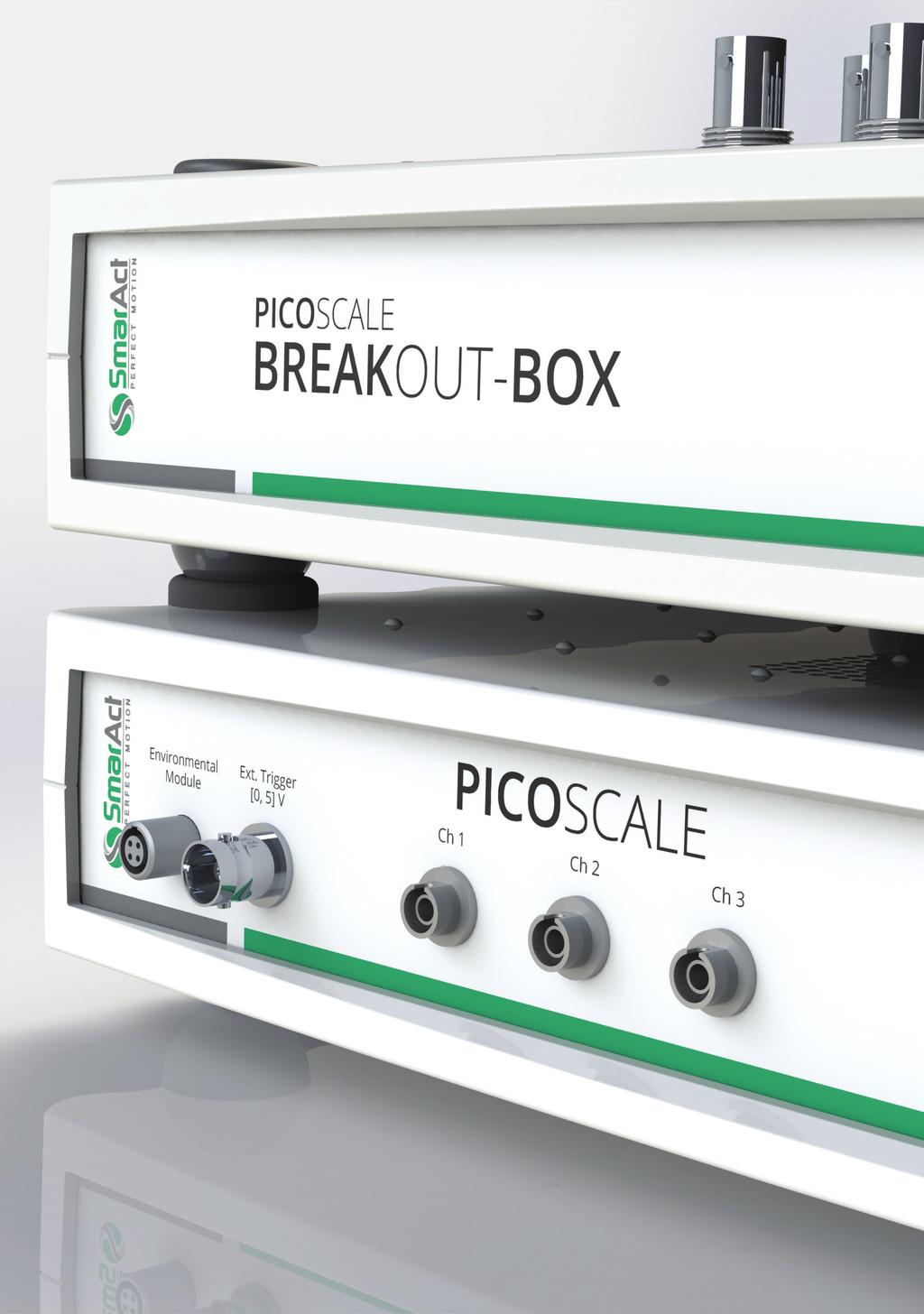
177 27
178 PICOSCALE SOFTWARE PICOSCALE CONTROL Convenient control of all PICOSCALE functions The PICOSCALE comes with a very powerful software package. This includes: PICOSCALE graphical user interface Adjustment panel Data visualization and processing PICOSCALE module configuration Environmental monitor PICOSCALE application programming interface (API) All drivers and libraries included Program your own software interface in C or LabVIEW Integration into large infrastructures The graphical user interface PICOSCALE Control allows easy access to all functions of the PICOSCALE. This includes convenience functions like adjustment routines, configuration of all firmware modules and - of course - visualization of PICOSCALE data. Overview of the functions of the PICOSCALE graphical user interface. On the left hand side, the connection as well as other information on the device s status is shown. On the right hand side, the main navigation panel is shown which allows fast access to all functions of the GUI. 28


 of a data source.")
179 PICOSCALE SOFTWARE PICOSCALE Control Data visualization PICOSCALE Control offers a very flexible and user-friendly Stream Monitor. The data can be visualized or processed in many different ways. Timeplot Classic panel to show time traces of data. Stacked timeplot Time traces of several data sources in individual plots. FFT Plot Display the Fast Fourier Transform (FFT) of a data source. Numeric Numeric display of data source values. XY Plot Plot one data source versus another, e.g. to generate Lissajous graphs. File Direct streaming of data sources into files. 29
180 PICOSCALE SOFTWARE PICOSCALE CONTROL Arrangement of plots PICOSCALE Control offers to arrange your plots in a very flexible way. The plot window can also be undocked so that you may monitor your data on a second screen while configuring PICOSCALE modules. The various plots can flexibly be arranged. You may, for example, set up a screen displaying the position data of all three PICOSCALE channels as well as their FFT - all in one window! 30
181 PICOSCALE SOFTWARE PICOSCALE Control Adjustment Monitor PICOSCALE Control allows you to maximize the signal quality of your measurement setup conveniently within the Adjustment Monitor. Adjustments Monitor: By maximizing the diameter of the Lissajous pattern and running the automated adjustment routine you can quickly obtain optimal performance of the PICOSCALE. 31
182 PICOSCALE SOFTWARE PICOSCALE CONTROL Module Configuration Within the PICOSCALE Control, all PICOSCALE modules can be configured. Module configuration: All PICOSCALE modules can conveniently be configured. Here, the panel for the Digital Differential Interface is shown, where you can define step size and step frequency of the AquadB protocol, for example. Configuration of the Calculation System. Up to three units can be configured using PICOSCALE data sources and user defined lookuptables. 32
183 PICOSCALE SOFTWARE PICOSCALE Control Environmental Monitor The PICOSCALE Environmental Module is able to record temperature, pressure and humidity of the vicinity of your experiment and correct the position data for changes of the ambient conditions. Without correction for these data, they would induce a virtual drift due to changes of the refractive index of air. Environmental Monitor: You can track drifts of the ambient conditions and correct the position data for these. PICOSCALE API AND DLL Tools to program your own software Beside the graphical user interface, the software package contains a full API and appropriate libraries. With these tools, the user may program his own code (for example in C or LabVIEW ) to control the PICOSCALE. 33


184 ACCESSORIES ACCESSORIES Enhance your possibilities SmarAct offers a great variety of accessories that can be purchased to make the PICOSCALE an even more powerful measurement tool or to make working with it even more convenient. Breakout-Box for convenient access to all PICOSCALE data sources. Environmental Module for correction of virtual drifts caused by air fluctuations. Self-centering adapter plates to mount PICOSCALE sensor heads. Open and closed-loop moveable mounts from SmarAct s motion devision to steer your sensor heads or targets remotely. Vacuum feedthroughs to use PICOSCALE sensor heads in vacuum. Various targets like mirrors and retroreflectors. 34
 signals are mapped to D- Sub 15 connectors.")
185 ACCESSORIES BREAKOUT-BOX Convenient access to all signals The PICOSCALE Breakout-Box (BOB) provides simple and convenient access to the many different interfaces of the PICOSCALE controller. Analog and digital GPIOs can be accessed via BNC connectors while the DDI (AquadB or Serial Data) signals are mapped to D- Sub 15 connectors. Additionally, a 12 V / 250 ma BNC pin is provided to supply optional external circuitry. Interfaces Digital1-4 Digital5-9 ADC1 ADC2, ADC3 DAC1 DAC2-5 DDI Ch1 Ch3 Power Properties 0-5 V output, rising/falling edge time < 50 ns V output, rising/falling edge time < 50 ns 16 bit resolution, 10 MSa/s, bandwidth 2 MHz, ± 10 V input voltage 16 bit resolution, 100 ksa/s, bandwidth 40 khz, ± 10 V input voltage 12 bit resolution, 10 MSa/s, bandwidth 2 MHz, ± 10 V output voltage 16 bit resolution, 200 ksa/s, bandwidth 150 khz, ± 10 V output voltage 0-5 V differential output 12 V / 250 ma source to supply external circuitry Order code: PS-BOB-V1.0-TAB Dimensions: (l x w x h): 33 x 27.5 x 8.5 cm³ 35

186 ACCESSORIES ENVIRONMENTAL MODULE Compact sensor of ambient conditions The environmental module is an accessory to measure temperature, humidity and pressure. This allows the compensation of the virtual drift induced by changes of the refractive index of air when measurements are performed in ambient conditions. Correction of the position data is performed in real-time on the controller. Feature Comment Temperature accuracy ± 200 mk Pressure accuracy ± 2 mbar Humidity accuracy ± 2 % Resulting position uncertainty < 1 ppm Connectivity Hot pluggable to PICOSCALE controller Order code: PS-EM-V1.0-TAB Dimensions (l x w x h): 54 x 34 x 16 mm³ 36

187 ACCESSORIES MCS2 Powerful motion controller The MCS2 is SmarAct s most powerful modular control system. This compact motion controller can be easily linked with the PICOSCALE displacement sensor. By using the interferometer s position data, the performance of closed-loop positioning can significantly be improved compared to standard sensor types. Furthermore, the results of the PICOSCALE Calculation System are available as data sources allowing for angular control, for example. Additionally, PICOSCALE sensor heads can be integrated into linear positioners upon request so that position feedback of the sensor heads may be used for closed-loop positioning even in harsh environments. 37

188 ACCESSORIES SENSOR HEAD MOUNTING OPTIONS Perfect tools to mount your sensors PICOSCALE sensor heads can easily be mounted to common optical mounts using adapter plates. We offer adapter plates to hold the most common sensor heads so that they can be fixed in ½ or 1 mounts. Outer diameter Inner diameter Order code 1/2" 4 mm PS-ACC-AP V1.1 1/2" 6 mm PS-ACC-AP V1.1 1/2" 9 mm PS-ACC-AP V1.1 1" 4 mm PS-ACC-AP V1.1 1" 6 mm PS-ACC-AP V1.1 1" 9 mm PS-ACC-AP V1.1 38

189 ACCESSORIES KINEMATIC MIRROR MOUNTS Remote alignment of your sensor heads Kinematic mirror mounts for remote alignment of sensor heads or targets. Closed-loop as well as open-loop mirror mounts are available. For the closed-loop systems inductive sensors are used. Size Order code 1/2" STT " STT-25.4 SmarAct offers mirror mounts with a great variety of sensor types and for specific environments like high vacuum and ultra-high vacuum. A full overview on all mirror mounts and their features can be found in the respective opto-mechanics catalog. Please contact SmarAct for details. 39
190 ACCESSORIES ADDITIONAL OPTICAL COMPONENTS what you might also need Vacuum feedthroughs Use PICOSCALE sensor heads in vacuum. Item Vacuum conditions Order code 1 channel DN 16 CF flange < mbar PS-VF-APC-UHV-1-CF16 1 channel DN 16 KF flange < 10-6 mbar PS-VF-APC-HV-1-KF16 1 channel DN 40 CF flange <10-11 mbar PS-VF-APC-UHV-1-CF40 1 channel DN 40 KF flange <10-6 mbar PS-VF-APC-HV-1-KF40 3 channel DN 40 CF flange <10-11 mbar PS-VF-APC-UHV-3-CF40 3 channel DN 40 KF flange <10-6 mbar PS-VF-APC-UHV-3-KF40 Fiber optic cleaning Optical fibers and connectors can be cleaned with this tool. Item Fiber cleaning pen Order code PSC: OneClick Cleaner Fiber optic patch cables Almost arbitrary length. Patch cable length Order code 1 m PS-ACC-PAT-APC-1M-APC 1.5 m PS-ACC-PAT-APC-1.5M-APC 5 m PS-ACC-PAT-APC-5M-APC 20 m PS-ACC-PAT-APC-20M-APC Reference targets We offer mirrors and retroreflectors with various dimensions. Please contact SmarAct. Order code: PS-ACC-TA-A-B-C -A Type -B Size in mm -C Shape / Type -M (mirror) 12.7 R (round) 25.4 S (square) -R (retro reflector) 3 C (corner cube)

191 APPLICATION EXAMPLES The PICOSCALE can be used for a great variety of applications. It is widely used in academic research and industrial environments. In the following you find a selection of applications that have been realized so far. However, please do not hesitate to contact SmarAct if you have different requests. Our direct and flexible customer support will be happy to help you! Overview: Position stability Various surfaces Differential measurements Radial run-out Scanning interferometer Angular measurements 41

192 APPLICATION EXAMPLES POSITION STABILITY MEASUREMENT The PICOSCALE interferometer allows the precise characterization of experimental setups. It achieves stabilities in the sub-nm region and can detect vibrations with single-pm amplitudes, which is demonstrated by the measurements presented here. Experimental setup: A PICOSCALE sensor head was aligned about 20 mm in front of a target mirror. The compact setup was placed in an enclosure to reduce air fluctuations. The mirror was mounted on a piezo element, so that small modulations of its position could be introduced Counts RMS signal amplitude / pm Deviation / pm Frequency / Hz Histogram of displacement data for a measurement with a standard sensor head over 20 seconds measurement time. No postprocessing of the data is performed. The standard deviation of the position data is 60 pm. Measurement of an artificially introduced vibration of the target mirror. The signal at 200 Hz is highly pronounced and the noise level is below 1 pm. 42

193 APPLICATION EXAMPLES MEASUREMENTS ON VARIOUS SURFACES The PICOSCALE optical working principle is based on a Michelson interferometer. This is beneficial in comparison with other interferometer types, especially if the target reflectivity is arbitrary. In a demonstrator setup we show that the PICOSCALE can measure displacements of targets with different reflectivities using the same sensor head in a single pass configuration. Experimental setup: A C01 sensor head is aligned to a sample holder where different targets are mounted. These targets have very different reflectivity and their displacement can be tracked with the same sensor head. The targets are: high reflective gold mirror LEGO brick ceramic plate glass plate polished aluminum cupper-beryllium sample 43
194 APPLICATION EXAMPLES DIFFERENTIAL MEASUREMENTS The PICOSCALE interferometer allows for differential measurements between a target mirror and a reference mirror. This allows measuring displacements relative to a certain fixed point of an experimental setup, as well as minimization of noise. Both arms are aligned in order to reduce environmental influences as much as possible. probe beam movable target reference beam fixed base Experimental setup for differential measurements. Both the probe and reference beam are guided to individual mirrors. The differential displacement of these two mirrors is measured with very high resolution. Measurement of small and slow modulations of the target mirror is possible even in ambient conditions: Position / nm FFT Amplitude / nm Time / seconds Frequency / Hz The probe mirror is modulated with a 0.5 Hz oscillation. The corresponding amplitude can be clearly seen in the time signal. Fourier transform of the time signal. The oscillation at 0.5 Hz is very pronounced. 44

195 APPLICATION EXAMPLES RADIAL RUN-OUT MEASUREMENT In many high precision applications the precise knowledge of the movement of a rotating target is of crucial interest. Radial run-out and wobble may have significant influence on the positioning process and thus need to be reduced. However, any correction requires an error signal, and thus the run-out and wobble need to be measured accurately. Subsequently, by applying adequate control loops or lookup-tables, the rotating target may be kept on the desired trajectory Experimental setup: Three line focusing sensor heads measure the eccentric movement and wobble of the rotating cylinder with surface irregularities. An eccentricity of more than 1 mm can be tracked using the line focusing sensor heads x y 120 o 60 o Position / µm o 0µ 1µ 2µ 3µ 4µ 0o Angle / degree Measurement of the eccentric movement. The x- and y-direction is shown. These are measured by sensor head 1 and 2, respectively. 240 o 300 o Calculated residues determined form measurements of sensor head 1 and 2. The eccentric movement of the pin is subtracted. 45


196 APPLICATION EXAMPLES SCANNING INTERFEROMETER A PICOSCALE laser interferometer was combined with a SmarAct 3D positioner system to create a scanning interferometer. The possibilities are demonstrated by measuring the thermal fluctuations of an atomic force microscope cantilever in order to calibrate its spring constant. This application also demonstrates the capability of the PICOSCALE to be used as a vibrometer. Experimental setup: The PICOSCALE probe beam is focused to a small sample which is mounted on a x-y-z translation stage. In addition to a microscope, the reflected intensity can be used to reconstruct an image of the sample which may allow for extremely compact setups even in harsh environments. Power / pm 2 /Hz 5 Fit 4.5 Data Frequency / Hz Microscope image of an AFM cantilever. scanned below the PICOSCALE probe beam. The sample can be Vibration of the sample. The thermal excitation is clearly pronounced. Here, the vibration of the second bending mode is shown. 46

197 APPLICATION EXAMPLES ANGULAR MEASUREMENTS The PICOSCALE allows for angular measurements in two dimensions, such as yaw and pitch of a target object. SmarAct provides a special sensor head assembly containing three sensor heads and retroreflectors. Furthermore, the PICOSCALE can be used as an encoder for closed-loop control of rotary axes. A direct interface between interferometer controller and the new SmarAct motion controller MCS2 is available. Experimental setup: Three PICOSCALE sensor heads are measuring the angle of the target plate to which three retroreflectors are mounted. Angle / degree 5 Tip 4 Tilt Time / seconds Measurement of the pitch and yaw of the target plate. Up to ±4 angular movement could be tracked with an angular resolution down to the µ level. Angles were calculated in real-time using the Calculation System module with minimal timing delay. 47


198 CLOSING REMARKS LOAN SERVICE AND CUSTOMIZATION Loan service SmarAct offers a loan service for the PICOSCALE product family. You may evaluate the functionality of all hardware and software in your specific experimental setup. The loan system comes with a broad selection of accessories that will make it easy for you to convince yourself on the outstanding performance of the PICOSCALE. The loan system comes with: PICOSCALE Controller with all firmware features Breakout-Box Environmental Module Broad selection of sensor heads Demonstration setup to evaluate basic functions at your desk MCS2 motion controller All necessary cables Customization This brochure gives an overview on the PICOSCALE interferometric displacement sensor and its product family. A selection of possible applications demonstrates the usability in all fields from fundamental research to industrial production. However, SmarAct constantly pushes the limits of the PICOSCALE resulting in more and more applications so it is worth checking our homepage regularly. SmarAct is outstanding in offering customized solutions, both in hardware and software. As SmarAct produces all main components in-house, we are very flexible and fast in prototyping. The PICOSCALE offers perfect compatibility with other SmarAct products like the linear and rotary stages, SmarPods, and many more. Our technical sales team and engineers will be very happy to find the optimal solution for your application. Please don t hesitate to contact us via or phone! 48
M-041 M-044 Tip/Tilt Stage
 M-041 M-044 Tip/Tilt Stage Piezo Drive Option for Nanometer Precision Ordering Information Linear Actuators & Motors M-041.00 Small Tilt Stage, Manual Micrometer Drive M-041.D01 Small Tilt Stage, DC-Motor
P-611.Z Piezo Z-Stage
 Physik Instrumente (PI) GmbH & Co. KG 2008. Subject to change without notice. All data are superseded by any new release. The newest release for data sheets is available for download at www.pi.ws. Cat120E
Compact Nanopositioning System Family with Long Travel Ranges
 P-620.1 P-629.1 PIHera Piezo Linear Stage Compact Nanopositioning System Family with Long Travel Ranges Physik Instrumente (PI) GmbH & Co. KG 2008. Subject to change without notice. All data are superseded
Angle Encoder Modules
 Angle Encoder Modules May 2015 Angle encoder modules Angle encoder modules from HEIDENHAIN are combinations of angle encoders and high-precision bearings that are optimally adjusted to each other. They
Fiber Optic Device Manufacturing
 Precision Motion Control for Fiber Optic Device Manufacturing Aerotech Overview Accuracy Error (µm) 3 2 1 0-1 -2 80-3 40 0-40 Position (mm) -80-80 80 40 0-40 Position (mm) Single-source supplier for precision
Q-Motion Miniature Linear Stage
 Q-Motion Miniature Stage Smallest linear stage with position control, high resolution and affordable price Q-521 Only 21 mm wide and 10 mm high Direct position measurement with integrated incremental,
PIHera Piezo Linear Precision Positioner
 PIHera Piezo Linear Precision Positioner Variable Travel Ranges and Axis Configuration P-620.1 P-629.1 Travel ranges 50 to 1800 µm Resolution to 0.1 nm Linearity error 0.02 % X, XY, Z versions; XYZ combination
Q-Motion Miniature Linear Stage
 Q-Motion Miniature Stage Piezo Motors for Small Dimensions, High Resolution, and a Favorable Price Q-522 Only 22 mm in width and 10 mm in height Direct position measurement with incremental with up to
PiezoMike Linear Actuator
 PiezoMike Linear Actuator With Position Sensor for Closed-Loop Operation N-472 High stability and holding force >100 N Self-locking at rest even when closed-loop control is switched off Compact design
P-810 P-830 Piezo Actuators
 P-810 P-830 Piezo Actuators For Light and Medium Loads The newest release for data sheets is available for download at www.pi.ws. Cat120E Inspirations2009 08/10.18 1-70 P-810 piezo actuators Outstanding
PIMag Precision Linear Stage
 PIMag Precision Linear Stage High Velocity and Precision due to Magnetic Direct Drive V-551 Travel ranges to 230 mm Velocity up to 0.5 m/s Absolute encoder with 1 nm resolution Highest precision with PIOne
PIglide AT3 Linear Stage with Air Bearings
 PIglide AT3 Linear Stage with Air Bearings High Performance Nanopositioning Stage A-123 Ideal for scanning applications or highprecision positioning Cleanroom compatible Size of the motion platform 210
Industrial Line. Nanoprecise Positioning at Ambient Temperature
 (c) 2018, attocube systems AG - Germany. attocube systems and the logo are trademarks of attocube systems AG. Registered and/or otherwise protected in various countries where attocube systems products
Rotary Encoder System Compact Model Range
 we set the standards RIK Rotary Encoder System Compact Model Range 2 Incremental rotary encoder Features Compact design, consisting of scanning head with round cable, 15pin D-sub connector and grating
RESOLUTE UHV absolute optical encoder
 L-9517-9530-01-L RESOLUTE UHV absolute optical encoder Clean RGA Low outgassing rate Bake-out temperature of 120 C True absolute non-contact optical encoder system: no batteries required Wide set-up tolerances
Fast Tip/Tilt Platform
 Fast Tip/Tilt Platform Short Settling Time and High Dynamic Linearity S-331 Tip/tilt angle up to 5 mrad, optical deflection angle up to 10 mrad (0.57 ) Parallel-kinematic design for identically high performance
This is how PI Does Measuring - Part I
 WHITEPAPER This is how PI Does Measuring - Part I This is how PI Does Measuring - Part I Measuring Environment / Measuring Equipment Portfolio / Data Evaluation Physik Instrumente (PI) GmbH & Co. KG, Auf
RESOLUTE FS absolute optical encoder with Siemens DRIVE-CLiQ serial communications
 L-9517-9701-01-C RESOLUTE FS absolute optical encoder with Siemens DRIVE-CLiQ serial communications True absolute non-contact optical encoder system: no batteries required ISO 13849: 2015 Pld IEC 61508:
Product Information. ERN 1085 Incremental Rotary Encoder with Z1 Track
 Product Information ERN 1085 Incremental Rotary Encoder with Z1 Track 02/2018 ERN 1085 Rotary encoder with mounted stator coupling Compact dimensions Blind hollow shaft 6 mm Z1 track for sine commutation
nano Motion Technology ANT130XY Series Two-Axis XY Direct-Drive Nanopositioning Stages ANT130XY Series NANO Technology Introduction
 ANTXY Series NANO Technology ANTXY Series Two-Axis XY Direct-Drive Nanopositioning Stages Integrated low-profile XY linear motor stage Nanometer-level performance in a large travel format High resolution
Automatic Testing of Photonics Components
 Automatic Testing of Photonics Components Fast, Accurate, and Suitable for Industry Physik Instrumente (PI) GmbH & Co. KG, Auf der Roemerstrasse 1, 76228 Karlsruhe, Germany Page 1 of 5 Silicon photonics
PRECISION AND DYNAMICS WITH PIEZO MOTOR STAGES Q-MOTION PIEZOWALK CONSTANT VELOCITY PRECISION REPEATABILITY SUBNANOMETER
 CUSTOM DESIGNS CONSTANT VELOCITY PRECISION AND DYNAMICS WITH PIEZO MOTOR STAGES MOTION CONTROL PIEZOMIKES COST EFFECTIVE REPEATABILITY SUBNANOMETER PARALLEL KINEMATICS COMPACT VACUUM PRECISION RELIABLE
absolute optical encoder for Panasonic serial communications
 L-9517-9460-05-B absolute optical encoder for Panasonic serial communications True absolute non-contact optical encoder system: no batteries required Wide set-up tolerances for quick and easy installation
Micro Precision Apertures
 National Aperture, Inc. Micro Precision Apertures Product Guide Precision apertures, targets and patterns, including round, slit, square, etc., for universal and high power applications National Aperture,
Synchronization Control Scheme for Hybrid Linear Actuator Based on One Common Position Sensor with Long Travel Range and Nanometer Resolution
 Sensors & Transducers 2014 by IFSA Publishing, S. L. http://www.sensorsportal.com Synchronization Control Scheme for Hybrid Linear Actuator Based on One Common Position Sensor with Long Travel Range and
Product Information. AK ERM 2xx0 TTR ERM 2x00 Modular Angle Encoders with Magnetic Scanning and Mechanical Fault Exclusion
 Product Information AK ERM 2xx0 TTR ERM 2x00 Modular Angle Encoders with Magnetic Scanning and Mechanical Fault Exclusion February 2017 ERM 2200 series Consisting of AK ERM 2280 and TTR ERM 2200 or TTR
RESOLUTE absolute optical encoder with Siemens DRIVE-CLiQ serial communications
 L-9517-9524-04-D RESOLUTE absolute optical encoder with Siemens DRIVE-CLiQ serial communications True absolute non-contact optical encoder system: no batteries required Wide set-up tolerances for quick
OPTICS IN MOTION. Introduction: Competing Technologies: 1 of 6 3/18/2012 6:27 PM.
 1 of 6 3/18/2012 6:27 PM OPTICS IN MOTION STANDARD AND CUSTOM FAST STEERING MIRRORS Home Products Contact Tutorial Navigate Our Site 1) Laser Beam Stabilization to design and build a custom 3.5 x 5 inch,
Fast Optical Form Measurements of Rough Cylindrical and Conical Surfaces in Diesel Fuel Injection Components
 Fast Optical Form Measurements of Rough Cylindrical and Conical Surfaces in Diesel Fuel Injection Components Thomas J. Dunn, Robert Michaels, Simon Lee, Mark Tronolone, and Andrew Kulawiec; Corning Tropel
queensgate a brand of Elektron Technology
 NanoSensors NX/NZ NanoSensor The NanoSensor is a non-contact position measuring system based on the principle of capacitance micrometry. Two sensor plates, a Target and a Probe, form a parallel plate capacitor.
Introduction... 3 Slits for AIR Operation... 4 Slits in Vacuum Vessels... 5 Slits for High Vacuum Operation... 6 Custom Slits... 7 Steel Slits...
 Introduction... 3 Slits for AIR Operation... 4 Slits in Vacuum Vessels... 5 Slits for High Vacuum Operation... 6 Custom Slits... 7 Steel Slits... 10 Non-magnetic Options for Slits... 12 Slits with Passive
RESOLUTE ETR (Extended Temperature Range) absolute encoder
 absolute encoder") L-9517-9420-02-H RESOLUTE ETR (Extended Temperature Range) absolute encoder True absolute non-contact optical encoder system: no batteries required Operates down to -40 C (-40 F) and up to +80 C (+176
L-9517-9420-02-H RESOLUTE ETR (Extended Temperature Range) absolute encoder True absolute non-contact optical encoder system: no batteries required Operates down to -40 C (-40 F) and up to +80 C (+176
New Long Stroke Vibration Shaker Design using Linear Motor Technology
 New Long Stroke Vibration Shaker Design using Linear Motor Technology The Modal Shop, Inc. A PCB Group Company Patrick Timmons Calibration Systems Engineer Mark Schiefer Senior Scientist Long Stroke Shaker
Screw Driven automation tables
 automation tables Precise multi-axis positioning systems play an integral part in today s semiconductor, computer peripheral, solar power, flat panel, life sciences, lab automation, biomedical and electronics
P-500 Series PZT Flexure Stages
 PZ 82E User Manual P-500 Series PZT Flexure Stages Release: 2.2.1 Date: 2005-10-24 This document describes the following products: P-517.2CL, P-517.3CD XY Stage, 100 x 100 µm P-517.3CL XYZ Stage, 100 x
ATX115SL/SLE Series Mechanical-Bearing, Screw-Driven Linear Stage
 ATX115/E Series Mechanical-Bearing, Screw-Driven Linear Stage Travel lengths up to 150 mm with anti-creep crossed-roller bearings Optional center-mounted linear encoder for direct position feedback Versatile
CamGrind L. Key data. Superproductive and perfect for batch production. A member of the United Grinding Group
 A member of the United Grinding Group Superproductive and perfect for batch production Key data The as a single-slide or two-slide machine allows you to machine shaft-type components with a length of up
Contents: Movement & Positioning News M&P 23, 1997, Text Only Version
 Contents: Sub-Nanometer Measurements Revolutionary 6-Axis Manipulator Hexapod Robot Improved Digital Piezo Controller Modular PZT Flexure Stages PZT Multilayer Benders for Fiberoptic Switching Windows
Precision Micro-Aperture Catalog
 National Aperture, Inc. Precision Micro-Aperture Catalog Version 2012 PLEASE CONTACT: Data Optics, Inc. Distributor for National Aperture, Inc. Phone: (734) 483-8228 (800) 321-9026 Fax: (734) 483-9879
Micro-manipulated Cryogenic & Vacuum Probe Systems
 Janis micro-manipulated probe stations are designed for non-destructive electrical testing using DC, RF, and fiber-optic probes. They are useful in a variety of fields including semiconductors, MEMS, superconductivity,
Mini-MAG Positioning Products
 Mini-MAG Positioning Products Miniature Linear Stage The Mini-MAG (MMG and MMX) line of miniature linear stages blends the ultimate in performance, reliability, and value, delivering nearly twice the accuracy
Description of options, upgrades and accessories for the laser beam stabilization system Compact
 Description of options, upgrades and accessories for the laser beam stabilization system Compact The basic configuration of the Compact laser beam stabilization system is fully equipped for stabilization
LENORD. +BAUER... automates motion. GEL 295x Customer-specific precision encoder. Technical Information Version General information.
 GEL 95x Customer-specific precision encoder LENORD +BAUER... automates motion. Technical Information Version 04- General information Extremly robust rotary encoder with stainless steel housing for measuring
6-Axis Nanopositioning Systems
 6-Axis Nanopositioning Systems Sophisticated Parallel-Kinematics Positioning Stages SOPHISTICATED PRECISE USER FRIENDLY W W W. P I. W S Click on the Images to Jump to Datasheet 6-Axis Nanopositioning Stages
ART50/100 Series. Mechanical-Bearing, Worm-Driven Rotary Stage. Low profile and small footprint. Ultra-fine resolution
 / Series Rotary Stages /100 Series Mechanical-Bearing, Worm-Driven Rotary Stage Low profile and small footprint Ultra-fine resolution Integral brushless servomotor or microstepping motor Optional aperture
absolute encoders and motors for -80 C
 absolute encoders and motors for -80 C motors Choosing a drive system for our application. To be taken into account: speed mechanical load characteristics smoothness of motion resolution temperature other
RPE Parallel Gripper- Electric Gripper Series
 1.14 RPE Parallel Gripper- Electric Gripper Series Failsafe Operation: Spring closed feature allows for full grip force during power off conditions. Electrically Actuated: Requires simple 24VDC pulsed
Manual Rotation Stages
 ~1mm Table mm Table Side-Mount, Aluminum Body, Slide Guide 88 mm Table Side-Mount, Aluminum Body, Slide Guide 88 mm Table Side-Mount, Aluminum Body, Cross-Roller or Slide Guide 9 mm Table Side-Mount, Aluminum
The New ID11 Nanoscope end-station A Nano-Tomography Scanner
 The New ID11 Nanoscope end-station A Nano-Tomography Scanner A focus on the sample positioning stages I. ID11 Beamline II. III. IV. Design architecture A rotation stage with nanometer-level performance
FPS Sensor Systems. Real-Time Interferometric Displacement Analysis PAGE 32 PAGE 1. pioneers of precision
 PAGE 32 PAGE 1 pioneers of precision (c) 2017, attocube systems AG - Germany. attocube systems and the logo are trademarks of attocube systems AG. Registered and/or otherwise protected in various countries
LEAD SCREW LINEAR ACTUATORS Profile Rail Linear Actuators
 LEAD SCREW LINEAR ACTUATORS Profile Rail Linear Actuators ITAR Helix Linear Technologies, Inc., Beachwood, Ohio COMPANY CULTURE Helix is a global supplier to the Medical Device, Life Science, Security,
RGH34 encoder system. Data sheet L A. RGH34 readhead and RGI34 interface: RGS40 scale:
 L-9517-978-01-A The Renishaw RGH34 series is a non-contact optical encoder system, providing highly-reliable positional feedback. This modular miniaturised encoder consists of an RGH34 readhead that reads
attocube systems Probe Stations for Extreme Environments CRYOGENIC PROBE STATION fundamentals principles of cryogenic probe stations
 PAGE 88 & 2008 2007 PRODUCT CATALOG CRYOGENIC PROBE STATION fundamentals...................... 90 principles of cryogenic probe stations attocps I.......................... 92 ultra stable cryogenic probe
R30D RVDTs DC-Operated Rotary Variable Differential Transformers
 R30D RVDTs DC-Operated Rotary Variable Differential Transformers RVDTs incorporate a proprietary noncontact design that dramatically improves long term reliability when compared to other traditional rotary
Mercury TM 1500V Vacuum Rated Digital Output Encoders
 Mercury TM 1500V Vacuum Rated Digital Output Encoders Factory Set Resolution to 0.50μm Reflective Linear and Rotary Vacuum Encoders Systems Customer Controller Typical Vacuum Encoder System Vacuum Wall
MA3. Miniature Absolute Magnetic Shaft Encoder Page 1 of 8. Description. Order Using #MA3 starting at $36.00 per unit. Features
 Page 1 of 8 Description The MA3 is a miniature rotary absolute shaft encoder that reports the shaft position over 360 with no stops or gaps. The MA3 is available with an analog or a pulse width modulated
Comp act Rotation Stages
 Comp act Rotation Stages Rotation Stage DT-6 N Rotation Stage RS-40 Rotation Stage DT-80 R Rotation Stage DT-0 www.pimicos.com // info@pi-usa.us Rotation Stage DT-80 Rotation Stage DT-34 // 08.832.346
PL112 PL140 PICMA Bender
 PL112 PL140 PICMA Bender All-Ceramic Bending Actuators with High Displacement Displacement to 2 mm Fast response in the ms range Nanometer resolution Low operating voltage Operating temperature up to 150
/DSM 070 HIGH MOMENT OVERLOAD CAPACITY, HIGH CAPACITY OF THE INTEGRATED RADIAL-AXIAL OUTPUT BEARINGS, HIGH DYNAMIC PERFORMANCE.
 /DSM 070 The high precision DriveSpin DS 070 actuators represent the medium-size serially produced member of the DriveSpin product range, meeting even the most demanding requirements of customers from
Precision Micro-Aperture Catalog
 National Aperture, Inc. Precision Micro-Aperture Catalog Version 2013 PLEASE CONTACT: Dan Gentile Sales Associate, National Aperture, Inc. Telephone: (603) 893-7393, (800) 360-4598, Fax: (603) 893-7857
Product Information ECI 1319S EQI 1331S. Absolute Rotary Encoders without Integral Bearing and with DRIVE-CLiQ Interface.
 Product Information ECI 1319S EQI 1331S Absolute Rotary Encoders without Integral Bearing and with DRIVE-CLiQ Interface Firmware 15 12/2018 ECI 1319S, EQI 1331S Rotary encoders for absolute position values
HexGen HEX HL Hexapod Six-DOF Positioning System
 HexGen HE300-230HL Hexapods and Robotics HexGen HE300-230HL Hexapod Six-DOF Positioning System Six degree-of-freedom positioning with linear travels to 60 mm and angular travels to 30 Precision design
Product Information. ECN 413 ECN 425 ERN 421 ERN 487 Rotary Encoders for Drive Control in Elevators
 Product Information ECN 413 ECN 425 ERN 421 ERN 487 Rotary Encoders for Drive Control in Elevators October 2007 ECN/ERN 400 Series Rotary Encoders with Integral Bearings for Elevator Technology Simple
PRODUCTS & SERVICES GUIDE
 PRODUCTS & SERVICES GUIDE IT S YOUR MOVE. 2 ROCKFORD BALL SCREW ABOUT US Ian McBain founded Rockford Ball Screw (RBS) in 1973 utilizing his years of experience in the industry with the goals of providing
QuantumScan-7 & 10 Moving Magnet Galvanometers
 QuantumScan-7 & 10 Moving Magnet Galvanometers QuantumScan-10 For 10-15 mm Beam Apertures Patent Pending Ceramic Rotor For Faster Step Response Patent Pending Rear Adjustable Stops 3X Greater Position
CamGrind L. Key data. Superproductive and perfect for batch production. A member of the UNITED GRINDING Group
 A member of the UNITED GRINDING Group Superproductive and perfect for batch production Key data The as a single-slide or two-slide machine allows you to machine shaft-type components with a length of up
n Measurable displacements between n Linearity: max. ± 0.05 % n Housing diameter 12.9 mm n Service life: 10 8 movements
 Potentiometric Displacement Sensor Miniature design Model 8709 Code: Delivery: Warranty: 8709 EN ex stock 24 months Application Potentiometric displacement sensors are used for direct, precise measurement
HexGen HEX HL Hexapod Six-DOF Positioning System
 HexGen HE300-230HL Hexapods and Robotics HexGen HE300-230HL Hexapod Six-DOF Positioning System Six degree-of-freedom positioning with linear travels to 60 mm and angular travels to 30 Precision design
10 Things to Consider when Acquiring a Nanopositioning System
 10 Things to Consider when Acquiring a Nanopositioning System There are many factors to consider when looking for nanopositioning piezo stages. This article will help explain some items that are important
HexGen HEX HL Hexapod Six-DOF Positioning System
 HexGen HE300-230HL Hexapods and Robotics HexGen HE300-230HL Hexapod Six-DOF Positioning System Six degree-of-freedom positioning with linear travels to 60 mm and angular travels to 30 Precision design
attocfm I for Surface Quality Inspection NANOSCOPY APPLICATION NOTE M01 RELATED PRODUCTS G
 APPLICATION NOTE M01 attocfm I for Surface Quality Inspection Confocal microscopes work by scanning a tiny light spot on a sample and by measuring the scattered light in the illuminated volume. First,
Miniature Nanopositioning Linear Stages
 Miniature Nanopositioning Linear Stages Flexure Drives, Closed Loop, Sub-Nanometer Precision HIGH PRECISION COMPACT LARGE VARIETY W W W. P I. W S Click on the Images to Jump to Datasheet Miniature Piezo
RSLA absolute high accuracy stainless steel scale
 L-9517-9387-03-C System features Single track optical absolute scale 30 µm nominal scale pitch ensures exceptional motion control performance Robust special composition stainless steel with defined coefficient
/DSM 050 HIGH MOMENT OVERLOAD CAPACITY, HIGH CAPACITY OF THE INTEGRATED RADIAL-AXIAL OUTPUT BEARINGS, HIGH DYNAMIC PERFORMANCE.
 /DSM 050 The high precision DriveSpin DS 050 actuators represent the smallest serially produced member of the DriveSpin product range, meeting even the most demanding requirements of customers from all
CamGrind S. Key data. Small and versatile. A member of the UNITED GRINDING Group
 A member of the UNITED GRINDING Group Small and versatile Key data The allows you to grind shaft-type workpieces with a length of up to 650 mm. This small, versatile grinding machine guarantees high-precision
Mercury TM 1500 Digital Output Encoder Systems
 Mercury TM 1500 Digital Output Encoder Systems Factory Set Resolution to 0.50μm Reflective Linear and Rotary Encoders Available with standard 15 pin D-sub connector or Micro connector Sensor the size of
RGH24 encoder system. Data sheet L C. RGH24 readhead: RGS20 scale:
 L-9517-9677-01-C Renishaw s RGH24 series is a non-contact optical encoder system. The compact readhead features a set-up led indicator, unique filtering optics for excellent dirt immunity, and integral
Study of Vee Plate Manufacturing Method for Indexing Table
 Study of Vee Plate Manufacturing Method for Indexing Table Yeon Taek OH Department of Robot System Engineering, Tongmyong University 428 Sinseon-ro, Nam-gu, Busan, Korea yeonoh@tu.ac.kr Abstract The indexing
H-824 Hexapod Microrobots
 Technical Note BRo, Contents H-824 Hexapod Microrobots Introduction... 1 Precision-Class 6-Axis Positioning System... 1 Model Overview... 1 Recommended Controller (to be ordered separately)... 1 Other
Tuning systems for superconducting cavities at Saclay
 Tuning systems for superconducting cavities at Saclay 1 MACSE: 1990: tuner in LHe bath at 1.8K TTF: 1995 tuner at 1.8K in the insulating vacuum SOLEIL: 1999 tuner at 4 K in the insulating vacuum Super-3HC:
MODELS SM SERVOTUBE MODULE
 Force» Peak: 46-92 N» Continuous: 6-27 N Maximum Velocity» Up to 10.8 m/s Feedback» Built-in position sensor» 1V pk-pk sin/cos» 6 micron repeatability» Optionally with high resolution encoder Range of
Motion Solutions for Digital Pathology. White Paper
 Motion Solutions for Digital Pathology White Paper Design Considerations for Digital Pathology Instruments With an ever increasing demand on throughput, pathology scanning applications are some of the
The Air Bearing Throughput Edge By Kevin McCarthy, Chief Technology Officer
 159 Swanson Rd. Boxborough, MA 01719 Phone +1.508.475.3400 dovermotion.com The Air Bearing Throughput Edge By Kevin McCarthy, Chief Technology Officer In addition to the numerous advantages described in
MINIATURE METAL BELLOWS COUPLINGS
 VERSATILE AND PRECISE. MINIATURE METAL BELLOWS COUPLINS SERIES MK 0.05 10 Nm THE ULTIMATE COUPLIN FROM 0.05 10 Nm BACKLASH FREE MINIATURE BELLOWS COUPLINS Areas of application: Ideal for precise transmission
M-227 DC-Mike Actuators
 MP 40E User Manual M-227 DC-Mike Actuators Release: 1.12 Date: 2003-06-02 This document describes the following Product(s): M-227.50 DC-Mike Drive, 50 mm M-227.25 DC-Mike Drive, 25 mm M-227.10 DC-Mike
HIGH PRECISION LINEAR ACTUATOR DEVELOPMENT
 HIGH PRECISION LINEAR ACTUATOR DEVELOPMENT I. Santos (1), G. Migliorero (2 (1) SENER-Structures & Mechanisms Section, Av. Zugazarte 56, 48930 Las Arenas (Vizcaya) Spain, Email: ignacio.santos@sener.es
Engineering Reference
 Engineering Reference Linear & Rotary Positioning Stages Table of Contents 1. Linear Positioning Stages...269 1.1 Precision Linear Angular Dynamic 1.2 Loading Accuracy Repeatability Resolution Straightness
ShaftGrind S. Key data. Compact and extremely versatile. A member of the UNITED GRINDING Group
 A member of the UNITED GRINDING Group Compact and extremely versatile Key data The allows you to grind shaft-type workpieces with a length of up to 650 mm. This small, versatile grinding machine guarantees
LENORD. +BAUER... automates motion. GEL 2351 with current or voltage interface. Technical information Version General. Features.
 GEL 2351 with current or voltage interface LENORD +BAUER... automates motion. Technical information Version 201-11 General Single turn absolute rotary encoder with a resolution of 16 bits Magneto-resistive
Parallel Grippers 1.1. For more information call us at: DESTACO or Fax: Visit us on the Internet at:
 Parallel Grippers PARALLEL GRIPPERS 1.1 PARALLEL GRIPPERS 1.2 Parallel Motion Gripper DPP Precision Series Precision parallel gripper featuring our DIRECTCONNECT mounting pattern Dual-V precision roller
XXXX e. X d.. X X X a
 The Heavy uty incremental encoder type 0H boasts a high degree of ruggedness in a very compact design. Its special construction makes it perfect for all applications in very harsh environments. / RoHS
Motion Solutions for Digital Pathology
 Parker Hannifin Electromechanical Dvision N. A. 1140 Sandy Hill Road Irwin, PA 1564203049 724-861-8200 www.parkermotion.com Motion Solutions for Digital Pathology By: Brian Handerhan and Jim Monnich Design
MINISLIDE MSQscale measuring system. Distance measuring system integrated into the MINISLIDE MSQ micro frictionless table
 MINISLIDE MSQscale measuring system Distance measuring system integrated into the MINISLIDE MSQ micro frictionless table Product catalog 2017 Latest version of the catalogs You can always find the latest
SGL Series. Single Guide Linear Motor Stage. Zero cogging and backlash ironless linear motor actuator. High speed and high acceleration
 SGL Series Single Guide Linear Motor Stage Direct drive Zero cogging and backlash ironless linear motor actuator High speed and high acceleration Fast response and quick settling time Smooth motion at
Scope of supply. Powerful precision P-SERIES K-SERIES T-SERIES MILLFORCE
 Scope of supply Powerful precision P-SERIES K-SERIES T-SERIES MILLFORCE 02 / Company 03 / Values 04 / Scope of supply 16 / Accessories 19 / Special machines UnionChemnitz Innovation based on tradition
eddyncdt 3010 Non-Contact Displacement Measuring Systems
 Eddy current sensors for displacement, distance and position Eddy current and inductive measurement system and sensors with micrometer resolution for linear measurement and displacement, distance and position
Product Information. RCN 2000 RCN 5000 RCN 8000 Absolute Angle Encoders for Safety-Related Applications
 Product Information RCN 2000 RCN 5000 RCN 8000 Absolute Angle Encoders for Safety-Related Applications September 2013 RCN 2000 series Absolute angle encoders for safety-related applications Safe absolute
Roller Guides C-Rail Systems Linear Guide Systems Ball-Bearing Guide Bushes Ball-bush block guides Shafts Accessories for Linear Slides
 Roller Guides C-Rail Systems Linear Guide Systems Ball-Bearing Guide Bushes Ball-bush block guides Shafts Accessories for Linear Slides Application example linear systems, drives and accessories 1 2 3
Product Information. ECA 4000 V Absolute Modular Angle Encoder for Application in High Vacuum
 Product Information ECA 4000 V Absolute Modular Angle Encoder for Application in High Vacuum December 2016 ECA 4412 V, ECA 4492 V Absolute angle encoder with high accuracy for use in high vacuum Steel
Temposonics. Magnetostrictive Linear Position Sensors. GB-M / GB-T SSI Data Sheet
 Temposonics Magnetostrictive Linear Position Sensors GB-M / GB-T SSI Sensor element and electronics can be changed Flat & compact sensor electronics housing Electrical connection is freely rotatable MEASURING