Deconvolution. Amy Mioduszewski National Radio Astronomy Observatory. Synthesis Imaging g in Radio Astronomy
|
|
|
- Blake Watts
- 5 years ago
- Views:
Transcription


1 Deconvolution Amy Mioduszewski National Radio Astronomy Observatory Synthesis Imaging g in Radio Astronomy (based on a talk given by David Wilner (CfA) at the NRAO s 2010 Synthesis Imaging Workshop) 1

")
2 The Fourier Domain acquire comfort o with the Fourier domain in older texts, functions and their Fourier transforms occupy upper and lower domains, as if functions circulated at ground level and their transforms in the underworld (Bracewell 1965) 2
3 Visibility and Sky Brightness from the van Citttert-Zernike theorem (TMS Chapter 14) for small fields of view: the complex visibility,v(u,v), is the 2D Fourier transform of the brightness on the sky,t(x,y) x T(x,y) y u,v (wavelengths) are spatial frequencies in E-W and N-S directions, i.e. the baseline lengths x,y (rad) are angles in tangent plane relative to a reference position in the E-W and N-S directions 3

 can")


 plane are")
 V(u,v) =")

4 The Fourier Transform Fourier theory states that any signal (including images) can be expressed as a sum of sinusoids signal 4 sinusoids sum Jean Baptiste Joseph Fourier (x,y) plane and (u,v) plane are conjugate coordinates T(x,y) V(u,v) = FT{T(x,y)} the Fourier Transform contains all information of the original 4
")


5 Some 2D Fourier Transform Pairs T(x,y) Amp{V(u,v)} δ Function Constant Gaussian Gaussian narrow features transform to wide features (and vice-versa) 5

}")


6 More 2D Fourier Transform Pairs T(x,y) Amp{V(u,v)} elliptical Gaussian elliptical Gaussian Disk Bessel sharp edges result in many high spatial frequencies 6


7 More 2D Fourier Transform Pairs T(x,y) Amp{V(u,v)} complicated structure on many scales 7
 Amp{V(u,v)} Pha{V(u,v)}")
8 Amplitude and Phase complex numbers: (real, imaginary) or (amplitude, phase) amplitude tells how much of a certain frequency component phase tells where this component is located T(x,y) Amp{V(u,v)} Pha{V(u,v)} 8
 or (amplitude, phase) amplitude tells how")
 Amp{V(u,v)}")
9 Amplitude and Phase complex numbers: (real, imaginary) or (amplitude, phase) amplitude tells how much of a certain frequency component phase tells where this component is located T(x,y) Amp{V(u,v)} Pha{V(u,v)} 9

 is real,")

 where *")

}")
10 Two Visibilities for One Measurement T(x,y) is real, but V(u,v) is complex (in general) V(-u,-v) = V*(u,v) where * is complex conjugation T(x,y) Amp{V(u,v)} V(u=0,v=0) integral of T(x,y)dxdy = total flux 10
11 Visibility and Sky Brightness 11
12 Visibility and Sky Brightness 12

 sample at a time Nt")
 plane by making use of Earth")


13 Aperture Synthesis sample V(u,v) at enough points to synthesis the equivalent large aperture of size (u max,v max ) 1 pair of telescopes 1 (u,v) sample at a time Nt telescopes number of samples = N(N-1)/2 fill in (u,v) plane by making use of Earth rotation: Sir Martin Ryle, 1974 Nobel Prize in Physics reconfigure physical layout of N telescopes for more Sir Martin Ryle configurations of 8 SMA antennas 345 GHz Dec = -24 deg 13

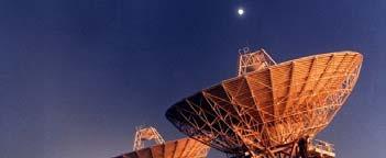
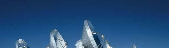

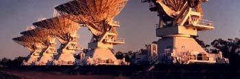
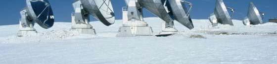
14 Examples of Millimeter Aperture Synthesis Telescopes EVLA ATCA IRAM PdBI CARMA SMA ALMA (2012+) 14

15 Imaging: g (u,v) plane Sampling in aperture synthesis, V(u,v) samples are limited by number of telescopes, and Earth-sky geometry high spatial frequencies maximum angular resolution low spatial frequencies extended structures invisible irregular within high/low limits sampling theorem violated information missing 15
16 Formal Description sample Fourier domain at discrete points the inverse Fourier transform is the convolution theorem tells us where (the point spread function) Fourier transform of sampled visibilities yields the true sky brightness convolved with the point spread function (the dirty image is the true image convolved with the dirty beam ) 16

")
")
 T")
")
17 Dirty Beam and Dirty Image b(x,y) (dirty beam) B(u,v) T(x,y) T D (x,y) (,y) (dirty image) 17


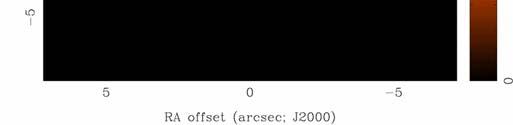
18 Dirty Beam Shape and N Antennas 2 Antennas 18


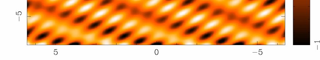
19 Dirty Beam Shape and N Antennas 3 Antennas 19


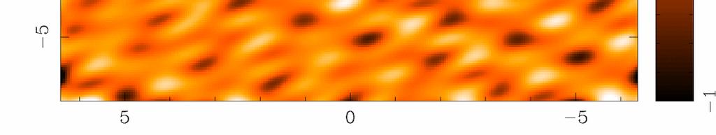
20 Dirty Beam Shape and N Antennas 4 Antennas 20
21 Dirty Beam Shape and N Antennas 5 Antennas 21
22 Dirty Beam Shape and N Antennas 6 Antennas 22


23 Dirty Beam Shape and N Antennas 7 Antennas 23


24 Dirty Beam Shape and N Antennas 8 Antennas 24


25 Dirty Beam Shape and N Antennas 8 Antennas x 6 Samples 25


26 Dirty Beam Shape and N Antennas 8 Antennas x 30 Samples 26


27 Dirty Beam Shape and N Antennas 8 Antennas x 60 Samples 27


28 Dirty Beam Shape and N Antennas 8 Antennas x 120 Samples 28


29 Dirty Beam Shape and N Antennas 8 Antennas x 240 Samples 29


30 Dirty Beam Shape and N Antennas 8 Antennas x 480 Samples 30


")
 T(x,y) visibilities")
31 How to analyze interferometer data? uv plane analysis best for simple sources, e.g. point sources, disks image plane analysis Fourier transform V(u,v) samples to image plane, get T D (x,y) but difficult to do science on dirty image deconvolve b(x,y) from T D (x,y) to determine (model of) T(x,y) visibilities dirty image sky brightness 31
32 Details of the Dirty Image Fourier Transform Fast Fourier Transform (FFT) much faster than simple Fourier summation, O(NlogN) for 2 N x 2 N image FFT requires data on regularly spaced grid aperture synthesis observations not on a regular grid Gridding is used to resample V(u,v) for FFT customary to use a convolution technique visibilities are noisy samples of a smooth function nearby visibilities not independent use special ( Spheroidal ) functions with nice properties fall off quickly in (u,v) plane (not too much smoothing) fall off quickly in image plane (avoid aliasing) 32

 A(x,y) primary beam response modifies sky brightness: T(x,y) A(x,y)T(x,y) ( correct with")
33 Primary Beam T(x,y) A telescope does not have uniform response across the entire sky main lobe approximately Gaussian, fwhm ~1.2λ/D, where D is ant diameter = primary beam limited field of view sidelobes, error beam (sometimes important) A(x,y) primary beam response modifies sky brightness: T(x,y) A(x,y)T(x,y) ( correct with division by A(x,y) in image plane SMA 345 GHz ALMA 690 GHz T(x,y) large A(x,y) small A(x,y) 33
34 pixel size Pixel Size and Image Size should satisfy sampling theorem for the longest baselines, Δx < 1/2 u max, Δy < 1/2 v max in practice, 3 to 5 pixels across the main lobe of the dirty beam (to aid deconvolution) e.g., SMA: 870 μm, 500 m baselines 600 kλ < 0.1 arcsec image size natural resolution in (u,v) plane samples FT{A(x,y)}, implies image size 2x primary beam e.g., SMA: 870 μm, 6 m telescope 2x 35 arcsec if there are bright sources in the sidelobes of A(x,y), then they will be aliased into the image (need to make a larger image) 34
 Natural weighting W(u,v) = 1/σ 2 (u,v) at points with data and zero")
 generally more weight to short baselines (large spatial scales), degrades d")
35 Dirty Beam Shape and Weighting g introduce weighting function W(u,v) W modifies sidelobes of dirty beam (W is also gridded for FFT) Natural weighting W(u,v) = 1/σ 2 (u,v) at points with data and zero elsewhere, where σ 2 (u,v) is the noise variance of the (u,v) sample maximizes point source sensitivity (lowest rms in image) generally more weight to short baselines (large spatial scales), degrades d resolution 35
36 Dirty Beam Shape and Weighting g Uniform weighting W(u,v) is inversely proportional to local density of (u,v) points, so sum of weights in a (u,v) cell is a constant (or zero) fills (u,v) plane more uniformly, so (outer) sidelobes are lower gives more weight to long baselines and therefore higher angular resolution degrades point source sensitivity (higher rms in image) can be trouble with sparse sampling: cells with few data points have same weight as cells with many data points 36


37 Dirty Beam Shape and Weighting g Robust (Briggs) weighting variant of uniform that avoids giving too much weight to cell with low natural weight implementations differ, e.g. S N is natural weight of a cell, S t is a threshold large threshold natural weighting small threshold uniform weighting an adjustable parameter that allows for continuous variation between highest angular resolution and optimal point source sensitivity 37

38 Dirty Beam Shape and Weighting g Tapering apodize the (u,v) sampling by a Gaussian t = tapering parameter (in kλ; arcsec) like smoothing in the image plane (convolution by a Gaussian) gives more weight to short baselines, degrades angular resolution degrades point source sensitivity but can improve sensitivity to extended structure could use elliptical Gaussian, other function limits to usefulness 38


39 Weighting g and Tapering: Noise Natural Robust x x0.36 σ=1.0 σ=1.66 Uniform 0.39x0.31 σ=3.7 Robust 0 + Taper x σ=1.7 39
40 Weighting g and Tapering: Summary imaging i parameters provide a lot of freedom appropriate choice depends on science goals Robust/Uniform Natural Taper Resolution higher medium lower Sidelobes lower higher depends Point Source lower maximum lower Sensitivity Extended Source lower medium higher Sensitivity 40


 from T D")
")


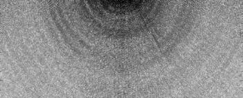
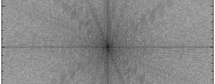
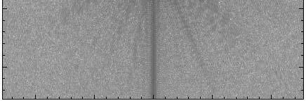
41 Deconvolution difficult to do science on dirty image deconvolve b(x,y) from T D (x,y) to recover T(x,y) information is missing, so be careful! (there s noise, too) dirty image CLEAN image 41
42 Deconvolution Philosophy to keep you awake at night an infinite it number of T(x,y) compatible with sampled V(u,v), i.e. invisible distributions R(x,y) where b(x,y) R(x,y) = 0 no data beyond u max,v max unresolved structure no data within u min,v min limit on largest size scale holes between u min,v min and u max,v max sidelobes noise undetected/corrupted structure in T(x,y) no unique prescription for extracting optimum estimate of true sky brightness from visibility data deconvolution uses non-linear techniques effectively interpolate/extrapolate samples of V(u,v) into unsampled regions of the (u,v) plane aims to find a sensible model of T(x,y) compatible with data requires aprioriassumptions assumptions about T(x,y) 42
43 Deconvolution Algorithms most ostcommon o ago algorithms in radio adoasto astronomyo CLEAN (Högbom 1974) a priori assumption: T(x,y) is a collection of point sources variants for computational efficiency, extended structure Maximum Entropy (Gull and Skilling 1983) aprioriassumption: assumption: T(x,y) is smooth and positive vast literature about the deep meaning of entropy (Bayesian) hybrid approaches of these can be effective deconvolution requires knowledge of beam shape and image noise properties (usually OK for aperture synthesis) atmospheric seeing can modify effective beam shape deconvolution process can modify image noise properties 43

 from residual map 5. If stopping criteria not reached, goto step 2 (an iteration) 6.")
44 Basic CLEAN Algorithm 1. Initialize a residual map to the dirty map a Clean component list to empty 2. Identify strongest feature in residual map as a point source 3. Add a fraction g (the loop gain) of this point source to the clean component list 4. Subtract the fraction g times b(x,y) from residual map 5. If stopping criteria not reached, goto step 2 (an iteration) 6. Convolve Clean component (cc) list by an estimate of the main lobe of the dirty beam (the Clean beam ) and add residual map to make the final restored image b(x,y) T D (x,y) 44
45 Basic CLEAN Algorithm (cont) stopping criteria residual map max < multiple of rms (when noise limited) residual map max < fraction of dirty map max (dynamic range limited) max number of clean components reached (no justification) loop gain good results for g ~ 01to lower values can work better for smoother emission, g ~ 0.05 easy to include a priori information about where to search for clean components ( clean boxes ) very useful but potentially dangerous! Schwarz (1978): CLEAN is equivalent to a least squares fit of sinusoids, id in the absense of noise 45
")


46 CLEAN T D (x,y) CLEAN model restored image residual map 46


47 CLEAN with Box T D (x,y) CLEAN model restored image residual map 47

 CLEAN")

48 CLEAN with Poor Choice of Box T D (x,y) CLEAN model restored image residual map 48
49 CLEAN Variants Clark CLEAN aims at faster speed for large images Högbom-like minor cycle w/ truncated dirty beam, subset of largest residuals in major cycle, cc s are FFT d and subtracted from the FFT of the residual image from the previous major cycle Cotton-Schwab CLEAN (MX) in major cycle, cc s are FFT d and subtracted from ungridded visibilities more accurate but slower (gridding steps repeated) Steer, Dewdny, Ito (SDI) CLEAN aims to supress CLEAN stripes in smooth, extended d emission i in minor cycles, any point in the residual map greater than a fraction (<1) of the maximum is taken as a cc Multi-Resolution l CLEAN aims to account for coupling between pixels by extended structure independently CLEAN a smooth map and a difference map, fewer cc s 49
50 Restored Images CLEAN beam size: natural choice is to fit the central peak of the dirty beam with elliptical Gaussian unit of deconvolved map is Jy per CLEAN beam area (= intensity, can convert to brightness temperature) minimize i i unit problems when adding dirty map residuals modest super resolution often OK, but be careful photometry should be done with caution CLEAN does not conserve flux (extrapolates) extended structure missed, attenuated, distorted phase errors (e.g. seeing) can spread signal around 50
51 Noise in Images point source sensitivity: s ty straightforward t a telescope area, bandwidth, integration time, weighting in image, modify noise by primary beam response extended source sensitivity: problematic not quite right to divide noise by n beams covered by source: smoothing = tapering, omitting data lower limitit Interferometers always missing flux at some spatial scale be careful with low signal-to-noise images if position known, 3σ OK for point source detection if position unknown, then 5σ required (flux biased by ~1σ) if < 6σ, cannot measure the source size (require ~3σ difference between long and short baselines) spectral lines may have unknown position, velocity, width 51
 subject to the")
 non-linear optimization solver due to")

52 Maximum Entropy Algorithm Maximize a measure of smoothness (the entropy) subject to the constraints b(x,y) M is the default image fast (NlogN) non-linear optimization solver due to Cornwell and Evans (1983) optional: convolve with Gaussian beam and add residual map to make image T D (x,y) 52
53 Maximum Entropy Algorithm (cont) easy to include apriori information o with default image flat default best only if nothing known (or nothing observed!) straightforward to generalize χ 2 to combine different observations/telescopes and obtain optimal image many measures of entropy available replace log with cosh emptiness (does not enforce positivity) less robust and harder to drive than CLEAN works well on smooth, extended emission trouble with point source sidelobes no noise estimate possible from image 53


54 Maximum Entropy T D (x,y) MAXEN model restored image residual map 54


55 Imaging g Results Natural Weight Beam CLEAN image 55


56 Imaging g Results Uniform Weight Beam CLEAN image 56


57 Imaging g Results Robust=0 Beam CLEAN image 57


58 Imaging g Results Robust=0 Beam MAXEN image 58
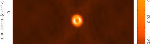
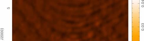
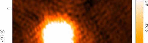
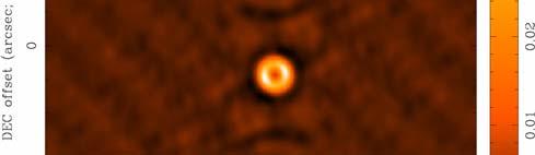
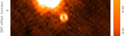
59 Tune Resolution/Sensitivity to suit Science e.g. Andrews, Wilner et al. 2009, ApJ, 700, 1502 SMA 870 μm images of transitional protoplanetary disks with resolved inner holes, note images of WSB AU 59


60 Missing Short Spacings Do the visibilities in the example discriminate between these models of the sky brightness distribution, T(x,y)? Yes but only on baselines shorter than ~100 kλ. 60


61 Missing Short Spacings: Demonstration T(x,y) CLEAN Image >100 kλ CLEAN Image 61
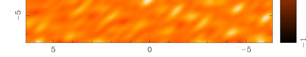
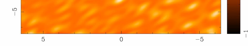
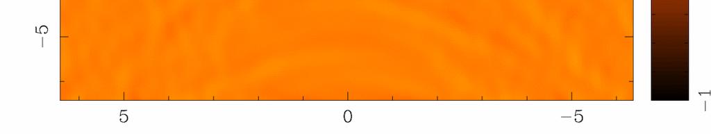
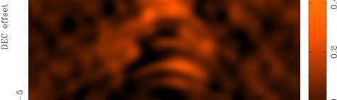
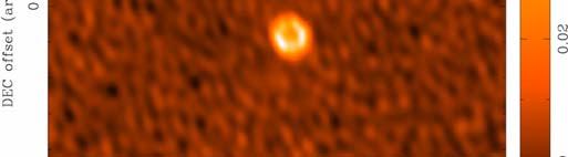
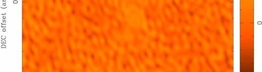
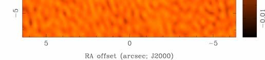
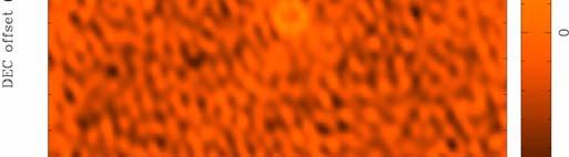
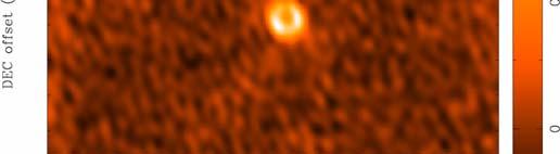
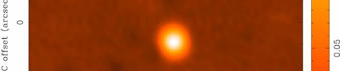
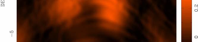
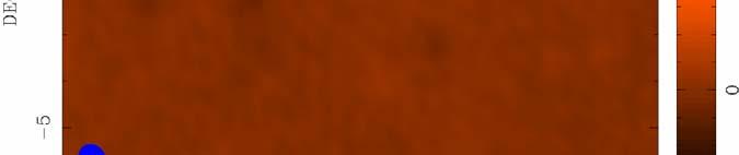
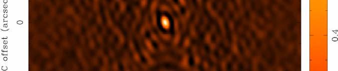
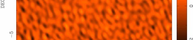
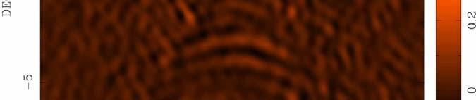
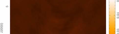
62 Missing Short Spacings: Real Data Observations of X- ray transient CI Cam at t15 and d5gh GHz with the VLBA+VLA1 u-v coverage for 1 5 GHz Because of the different frequencies they have different uv- coverage u-v cove erage for 5 GH Hz 62
63 Missing Short Spacings: Real Data 15 GHz 5 GHz Two possible explanations of differences between frequencies: 1. Real differences in the spectral index across the source 2. u-v coverage differences How do we tell the difference? Unfortunately, the standard wisdom is that all you have to do is convolve the 15 GHz 5 GHz 15 GHz image image put image to the 5 GHz beam. observed convolved with the 15 GHz u-v coverage 5 GHz But beam this only takes account of the differences in the long spacings and ignores the hole in the middle. A better approach is to put a model of the 5 GHz image though the u-v coverage of the 15 GHz data.
64 Low Spatial Frequencies (I) Large Single Telescope make an image by scanning across the sky all Fourier components from 0 to D sampled, where D is the telescope diameter (weighting depends on illumination) density of uv points (u,v) Fourier transform single dish map = T(x,y) A(x,y), then divide by a(x,y) = FT{A(x,y)}, to estimate V(u,v) choose D large enough to overlap interferometer samples of V(u,v) and avoid using data where a(x,y) becomes small 64


65 Low Spatial Frequencies (II) separate array of smaller telescopes use smaller telescopes observe short baselines not accessible to larger telescopes shortest baselines from larger telescopes total power maps ALMA with ACA 50 x 12 m: 12 m to 14 km +12 x 7 m: fills 7 to 12 m + 4 x 12 m: fills 0 to 7 m 65
66 Low Spatial Frequencies (III) mosaic with a homogeneous array recover a range of spatial frequencies around the nominal baseline b using knowledge of A(x,y) (Ekers and Rots 1979) (and get shortest baselines from total power maps) V(u,v) is linear combination of baselines from b-d Dto b+d depends on pointing direction (x o,y o ) as well as (u,v) (u,v) Fourier transform with respect to pointing direction (x o,y o ) 66

67 Measures of Image Quality dynamic range ratio of peak brightness to rms noise in a region void of emission (common in astronomy) an easy to calculate lower limit to the error in brightness in a non-empty region fidelity difference between any produced image and the correct image a convenient measure of how accurately it is possible to make an image that reproduces the brightness distribution on the sky need a priori knowledge of correct image to calculate fidelity image = input model / difference = model beam / abs( model beam reconstruction ) fidelity is the inverse of the relative error in practice, lowest values of difference need to be truncated 67
68 Measures of Image Quality ALMA Memo #387 Pety et al. ALMA Level 1 Science Goal #3 ALMA will have: The ability to provide precise images at an angular resolution of 0.1". Here the term precise image means accurately representing the sky brightness at all points where the brightness is greater than 0.1% of the peak /image brightness. 68
69 Self Calibration a priori calibration not perfect interpolated t from different time, different sky direction from source basic idea of self calibration correct for antenna-based errors together with imaging g works because at each time, measure N complex gains and N(N-1)/2 visibilities source structure t represented by small number of parameters highly overconstrained problem if N large and source simple in practice, an iterative, non-linear relaxation process assume initial model solve for time dependent gains form new sky model from corrected data using e.g. CLEAN solve for new gains requires sufficient i signal-to-noise i ratio for each solution interval loses absolute phase and therefore position information dangerous with small N, complex source, low signal-to-noise ose 69
70 Concluding Remarks interferometry samples visibilities that are related to a sky brightness image by the Fourier transform deconvolution corrects for incomplete sampling remember there are usually an infinite number of images compatible with the sampled visibilities astronomer must use judgement in imaging process imaging is generally fun (compared to calibration) many, many issues not covered today (see References) 70
71 References Thompson, A.R., Moran, J.M., & Swensen, G.W. 2004, Interferometry and Synthesis in Radio Astronomy 2nd edition (WILEY-VCH) NRAO Summer School proceedings Perley, R.A., Schwab, F.R. & Bridle, A.H., eds. 1989, ASP Conf. Series 6, Synthesis Imaging in Radio Astronomy (San Francisco: ASP) Chapter 6: Imaging (Sramek & Schwab), Chapter 8: Deconvolution (Cornwell) T. Cornwell 2002, S. Bhatnagar 2004, 2006 Imaging g and Deconvolution IRAM Summer School proceedings Guilloteau, S., ed. 2000, IRAM Millimeter Interferometry Summer School Chapter 13: Imaging Principles, Chapter 16: Imaging in Practice (Guilloteau) J. Pety 2004, 2006, 2008 Imaging and Deconvolution lectures CARMA Summer School proceedings - M. Wright The Complete Mel Lectures 71
Introduction to Imaging in CASA
 Introduction to Imaging in CASA Mark Rawlings, Juergen Ott (NRAO) Atacama Large Millimeter/submillimeter Array Expanded Very Large Array Robert C. Byrd Green Bank Telescope Very Long Baseline Array Overview
Large-field imaging. Frédéric Gueth, IRAM Grenoble. 7th IRAM Millimeter Interferometry School 4 8 October 2010
 Large-field imaging Frédéric Gueth, IRAM Grenoble 7th IRAM Millimeter Interferometry School 4 8 October 2010 Large-field imaging The problems The field of view is limited by the antenna primary beam width
Imaging Simulations with CARMA-23
 BIMA memo 101 - July 2004 Imaging Simulations with CARMA-23 M. C. H. Wright Radio Astronomy laboratory, University of California, Berkeley, CA, 94720 ABSTRACT We simulated imaging for the 23-antenna CARMA
Basic Mapping Simon Garrington JBO/Manchester
 Basic Mapping Simon Garrington JBO/Manchester Introduction Output from radio arrays (VLA, VLBI, MERLIN etc) is just a table of the correlation (amp. & phase) measured on each baseline every few seconds.
Introduction to Radio Interferometry Sabrina Stierwalt Alison Peck, Jim Braatz, Ashley Bemis
 Introduction to Radio Interferometry Sabrina Stierwalt Alison Peck, Jim Braatz, Ashley Bemis Atacama Large Millimeter/submillimeter Array Expanded Very Large Array Robert C. Byrd Green Bank Telescope Very
Principles of Radio Interferometry. Ast735: Submillimeter Astronomy IfA, University of Hawaii
 Principles of Radio Interferometry Ast735: Submillimeter Astronomy IfA, University of Hawaii 1 Resources IRAM millimeter interferometry school hdp://www.iram- inshtute.org/en/content- page- 248-7- 67-248-
Wide-Band Imaging. Outline : CASS Radio Astronomy School Sept 2012 Narrabri, NSW, Australia. - What is wideband imaging?
 Wide-Band Imaging 24-28 Sept 2012 Narrabri, NSW, Australia Outline : - What is wideband imaging? - Two Algorithms Urvashi Rau - Many Examples National Radio Astronomy Observatory Socorro, NM, USA 1/32
Fourier Transforms in Radio Astronomy
 Fourier Transforms in Radio Astronomy Kavilan Moodley, UKZN Slides taken from N Gupta s lectures: SKA School 2013 van-cittert Zernike theorem Extended, quasi-monochromatic, incoherent source X (l,m) Y
Heterogeneous Array Imaging with the CARMA Telescope
 Heterogeneous Array Imaging with the CARMA Telescope M. C. H. Wright Radio Astronomy laboratory, University of California, Berkeley, CA, 94720 February 1, 2011 ACKNOWLEDGMENTS Many people have made the
Mosaicking. Brian Mason (NRAO) Sixteenth Synthesis Imaging Workshop May 2018
 Sixteenth Synthesis Imaging Workshop May 2018") Mosaicking Brian Mason (NRAO) Sixteenth Synthesis Imaging Workshop 16-23 May 2018 The simplest observing scenario for an interferometer: Source at known location Size
Mosaicking Brian Mason (NRAO) Sixteenth Synthesis Imaging Workshop 16-23 May 2018 The simplest observing scenario for an interferometer: Source at known location Size
Introduction to Radio Interferometry Anand Crossley Alison Peck, Jim Braatz, Ashley Bemis (NRAO)
") Introduction to Radio Interferometry Anand Crossley Alison Peck, Jim Braatz, Ashley Bemis (NRAO) Atacama Large Millimeter/submillimeter Array Expanded Very Large Array Robert C. Byrd Green Bank Telescope
Introduction to Radio Interferometry Anand Crossley Alison Peck, Jim Braatz, Ashley Bemis (NRAO) Atacama Large Millimeter/submillimeter Array Expanded Very Large Array Robert C. Byrd Green Bank Telescope
The Basics of Radio Interferometry. Frédéric Boone LERMA, Observatoire de Paris
 The Basics of Radio Interferometry LERMA, Observatoire de Paris The Basics of Radio Interferometry The role of interferometry in astronomy = role of venetian blinds in Film Noir 2 The Basics of Radio Interferometry
Wide Bandwidth Imaging
 Wide Bandwidth Imaging 14th NRAO Synthesis Imaging Workshop 13 20 May, 2014, Socorro, NM Urvashi Rau National Radio Astronomy Observatory 1 Why do we need wide bandwidths? Broad-band receivers => Increased
INTERFEROMETRY: II Nissim Kanekar (NCRA TIFR)
") INTERFEROMETRY: II Nissim Kanekar (NCRA TIFR) WSRT GMRT VLA ATCA ALMA SKA MID PLAN Introduction. The van Cittert Zernike theorem. A 2 element interferometer. The fringe pattern. 2 D and 3 D interferometers.
INTERFEROMETRY: II Nissim Kanekar (NCRA TIFR) WSRT GMRT VLA ATCA ALMA SKA MID PLAN Introduction. The van Cittert Zernike theorem. A 2 element interferometer. The fringe pattern. 2 D and 3 D interferometers.
Sideband Smear: Sideband Separation with the ALMA 2SB and DSB Total Power Receivers
 and DSB Total Power Receivers SCI-00.00.00.00-001-A-PLA Version: A 2007-06-11 Prepared By: Organization Date Anthony J. Remijan NRAO A. Wootten T. Hunter J.M. Payne D.T. Emerson P.R. Jewell R.N. Martin
Fundamentals of Radio Interferometry
 Fundamentals of Radio Interferometry Rick Perley, NRAO/Socorro Fourteenth NRAO Synthesis Imaging Summer School Socorro, NM Topics Why Interferometry? The Single Dish as an interferometer The Basic Interferometer
Radio Interferometer Array Point Spread Functions I. Theory and Statistics
 ALMA MEMO 389 Radio Interferometer Array Point Spread Functions I. Theory and Statistics David Woody Abstract This paper relates the optical definition of the PSF to radio interferometer arrays. The statistical
Adaptive selective sidelobe canceller beamformer with applications in radio astronomy
 Adaptive selective sidelobe canceller beamformer with applications in radio astronomy Ronny Levanda and Amir Leshem 1 Abstract arxiv:1008.5066v1 [astro-ph.im] 30 Aug 2010 We propose a new algorithm, for
Introduction to Interferometry. Michelson Interferometer. Fourier Transforms. Optics: holes in a mask. Two ways of understanding interferometry
 Introduction to Interferometry P.J.Diamond MERLIN/VLBI National Facility Jodrell Bank Observatory University of Manchester ERIS: 5 Sept 005 Aim to lay the groundwork for following talks Discuss: General
Radio Interferometry. Xuening Bai. AST 542 Observational Seminar May 4, 2011
 Radio Interferometry Xuening Bai AST 542 Observational Seminar May 4, 2011 Outline Single-dish radio telescope Two-element interferometer Interferometer arrays and aperture synthesis Very-long base line
Wide-field, wide-band and multi-scale imaging - II
 Wide-field, wide-band and multi-scale imaging - II Radio Astronomy School 2017 National Centre for Radio Astrophysics / TIFR Pune, India 28 Aug 8 Sept, 2017 Urvashi Rau National Radio Astronomy Observatory,
Fundamentals of Interferometry
 Fundamentals of Interferometry ERIS, Rimini, Sept 5-9 2011 Outline What is an interferometer? Basic theory Interlude: Fourier transforms for birdwatchers Review of assumptions and complications Interferometers
GPU based imager for radio astronomy
 GPU based imager for radio astronomy GTC2014, San Jose, March 27th 2014 S. Bhatnagar, P. K. Gupta, M. Clark, National Radio Astronomy Observatory, NM, USA NVIDIA-India, Pune NVIDIA-US, CA Introduction
Dealing with Noise. Stéphane GUILLOTEAU. Laboratoire d Astrophysique de Bordeaux Observatoire Aquitain des Sciences de l Univers
 Dealing with Noise Stéphane GUILLOTEAU Laboratoire d Astrophysique de Bordeaux Observatoire Aquitain des Sciences de l Univers I - Theory & Practice of noise II Low S/N analysis Outline 1. Basic Theory
Fundamentals of Interferometry
 Fundamentals of Interferometry ERIS, Dwingeloo, Sept 8-13 2013 Outline What is an interferometer? Basic theory Interlude: Fourier transforms for birdwatchers Review of assumptions and complications Interferometers
EVLA and LWA Imaging Challenges
 EVLA and LWA Imaging Challenges Steven T. Myers IGPP, Los Alamos National Laboratory and National Radio Astronomy Observatory, Socorro, NM 1 EVLA key issues 2 Key algorithmic issues ambitious goals / hard
Plan for Imaging Algorithm Research and Development
 Plan for Imaging Algorithm Research and Development S. Bhatnagar July 05, 2009 Abstract Many scientific deliverables of the next generation radio telescopes require wide-field imaging or high dynamic range
REDUCTION OF ALMA DATA USING CASA SOFTWARE
 REDUCTION OF ALMA DATA USING CASA SOFTWARE Student: Nguyen Tran Hoang Supervisor: Pham Tuan Anh Hanoi, September - 2016 1 CONTENS Introduction Interferometry Scientific Target M100 Calibration Imaging
Spectral Line II: Calibration and Analysis. Spectral Bandpass: Bandpass Calibration (cont d) Bandpass Calibration. Bandpass Calibration
 Bandpass Calibration. Bandpass Calibration") Spectral Line II: Calibration and Analysis Bandpass Calibration Flagging Continuum Subtraction Imaging Visualization Analysis Spectral Bandpass: Spectral frequency response of antenna to a spectrally flat
Spectral Line II: Calibration and Analysis Bandpass Calibration Flagging Continuum Subtraction Imaging Visualization Analysis Spectral Bandpass: Spectral frequency response of antenna to a spectrally flat
Atacama Large Millimeter/submillimeter Array Expanded Very Large Array Robert C. Byrd Green Bank Telescope Very Long Baseline Array
 Atacama Large Millimeter/submillimeter Array Expanded Very Large Array Robert C. Byrd Green Bank Telescope Very Long Baseline Array Self-Calibration Ed Fomalont (NRAO) ALMA Data workshop Dec. 2, 2011 Atacama
A model for the SKA. Melvyn Wright. Radio Astronomy laboratory, University of California, Berkeley, CA, ABSTRACT
 SKA memo 16. 21 March 2002 A model for the SKA Melvyn Wright Radio Astronomy laboratory, University of California, Berkeley, CA, 94720 ABSTRACT This memo reviews the strawman design for the SKA telescope.
Next Generation Very Large Array Memo No. 47 Resolution and Sensitivity of ngvla-revb. C.L. Carilli (NRAO)
") Next Generation Very Large Array Memo No. 47 Resolution and Sensitivity of ngvla-revb C.L. Carilli (NRAO) Abstract I investigate the noise performance vs. resolution for the new ngvlarevb configuration.
Next Generation Very Large Array Memo No. 47 Resolution and Sensitivity of ngvla-revb C.L. Carilli (NRAO) Abstract I investigate the noise performance vs. resolution for the new ngvlarevb configuration.
Practicalities of Radio Interferometry
 Practicalities of Radio Interferometry Rick Perley, NRAO/Socorro 13 th Synthesis Imaging Summer School 29 May 5 June, 2012 Socorro, NM Topics Practical Extensions to the Theory: Finite bandwidth Rotating
Volume 82 VERY LONG BASELINE INTERFEROMETRY AND THE VLBA. J. A. Zensus, P. J. Diamond, and P. J. Napier
 ASTRONOMICAL SOCIETY OF THE PACIFIC CONFERENCE SERIES Volume 82 VERY LONG BASELINE INTERFEROMETRY AND THE VLBA Proceedings of a Summer School held in Socorro, New Mexico 23-30 June 1993 NRAO Workshop No.
Error Recognition Emil Lenc (and Arin)
") Error Recognition Emil Lenc (and Arin) University of Sydney / CAASTRO www.caastro.org CASS Radio Astronomy School 2017 Based on lectures given previously by Ron Ekers and Steven Tingay CSIRO; Swinburne
Error Recognition Emil Lenc (and Arin) University of Sydney / CAASTRO www.caastro.org CASS Radio Astronomy School 2017 Based on lectures given previously by Ron Ekers and Steven Tingay CSIRO; Swinburne
Technical Considerations: Nuts and Bolts Project Planning and Technical Justification
 Technical Considerations: Nuts and Bolts Project Planning and Technical Justification Atacama Large Millimeter/submillimeter Array Expanded Very Large Array Robert C. Byrd Green Bank Telescope Very Long
Fundamentals of Radio Interferometry. Robert Laing (ESO)
") Fundamentals of Radio Interferometry Robert Laing (ESO) 1 ERIS 2015 Objectives A more formal approach to radio interferometry using coherence functions A complementary way of looking at the technique Simplifying
Fundamentals of Radio Interferometry Robert Laing (ESO) 1 ERIS 2015 Objectives A more formal approach to radio interferometry using coherence functions A complementary way of looking at the technique Simplifying
Phased Array Feeds A new technology for wide-field radio astronomy
 Phased Array Feeds A new technology for wide-field radio astronomy Aidan Hotan ASKAP Project Scientist 29 th September 2017 CSIRO ASTRONOMY AND SPACE SCIENCE Outline Review of radio astronomy concepts
Phased Array Feeds A new technology for multi-beam radio astronomy
 Phased Array Feeds A new technology for multi-beam radio astronomy Aidan Hotan ASKAP Deputy Project Scientist 2 nd October 2015 CSIRO ASTRONOMY AND SPACE SCIENCE Outline Review of radio astronomy concepts.
ALMA Memo #289 Atmospheric Noise in Single Dish Observations Melvyn Wright Radio Astronomy Laboratory, University of California, Berkeley 29 February
 ALMA Memo #289 Atmospheric Noise in Single Dish Observations Melvyn Wright Radio Astronomy Laboratory, University of California, Berkeley 29 February 2000 Abstract Atmospheric noise and pointing fluctuations
Next Generation Very Large Array Memo No. 16 More on Synthesized Beams and Sensitivity. C.L. Carilli, NRAO, PO Box O, Socorro, NM
 Next Generation Very Large Array Memo No. 16 More on Synthesized Beams and Sensitivity C.L. Carilli, NRAO, PO Box O, Socorro, NM Abstract I present further calculations on synthesized beams and sensitivities
Cross Correlators. Jayce Dowell/Greg Taylor. University of New Mexico Spring Astronomy 423 at UNM Radio Astronomy
 Cross Correlators Jayce Dowell/Greg Taylor University of New Mexico Spring 2017 Astronomy 423 at UNM Radio Astronomy Outline 2 Re-cap of interferometry What is a correlator? The correlation function Simple
EVLA Memo 146 RFI Mitigation in AIPS. The New Task UVRFI
 EVLA Memo 1 RFI Mitigation in AIPS. The New Task UVRFI L. Kogan, F. Owen 1 (1) - National Radio Astronomy Observatory, Socorro, New Mexico, USA June, 1 Abstract Recently Ramana Athrea published a new algorithm
ATCA Antenna Beam Patterns and Aperture Illumination
 1 AT 39.3/116 ATCA Antenna Beam Patterns and Aperture Illumination Jared Cole and Ravi Subrahmanyan July 2002 Detailed here is a method and results from measurements of the beam characteristics of the
Parameterized Deconvolution for Wide-Band Radio Synthesis Imaging
 Parameterized Deconvolution for Wide-Band Radio Synthesis Imaging Urvashi Rao Venkata Ph.D. Thesis Defense Department of Physics, New Mexico Institute of Mining and Technology 17 May 2010 Advisors / Committee
Radio Astronomy: SKA-Era Interferometry and Other Challenges. Dr Jasper Horrell, SKA SA (and Dr Oleg Smirnov, Rhodes and SKA SA)
") Radio Astronomy: SKA-Era Interferometry and Other Challenges Dr Jasper Horrell, SKA SA (and Dr Oleg Smirnov, Rhodes and SKA SA) ASSA Symposium, Cape Town, Oct 2012 Scope SKA antenna types Single dishes
Radio Astronomy: SKA-Era Interferometry and Other Challenges Dr Jasper Horrell, SKA SA (and Dr Oleg Smirnov, Rhodes and SKA SA) ASSA Symposium, Cape Town, Oct 2012 Scope SKA antenna types Single dishes
Atacama Large Millimeter/submillimeter Array Expanded Very Large Array Robert C. Byrd Green Bank Telescope Very Long Baseline Array
 Atacama Large Millimeter/submillimeter Array Expanded Very Large Array Robert C. Byrd Green Bank Telescope Very Long Baseline Array Basics of Interferometry Data Reduction Scott Schnee (NRAO) ALMA Data
High Fidelity Imaging of Extended Sources. Rick Perley NRAO Socorro, NM
 High Fidelity Imaging of Extended Sources Rick Perley NRAO Socorro, NM A Brief History of Calibration (VLA) An Amazing Fact: The VLA was proposed, and funded, without any real concept of how to calibrate
Practicalities of Radio Interferometry
 Practicalities of Radio Interferometry Rick Perley, NRAO/Socorro Fourth INPE Course in Astrophysics: Radio Astronomy in the 21 st Century Topics Practical Extensions to the Theory: Finite bandwidth Rotating
Why? When? How What to do What to worry about
 Tom Muxlow Data Combination Why? When? How What to do What to worry about Combination imaging or separate imaging??..using (e-)merlin (e-)merlin covers a unique range of telescope separations, intermediate
USE OF FT IN IMAGE PROCESSING IMAGE PROCESSING (RRY025)
") IMAGE PROCESSIG (RRY25) USE OF FT I IMAGE PROCESSIG Optics- originofimperfectionsinimagingsystems(limited resolution/blurring related to 2D FTs)- need to understand using Continuous FT. Sampling -Capturecontinuousimageontoasetofdiscrete
IMAGE PROCESSIG (RRY25) USE OF FT I IMAGE PROCESSIG Optics- originofimperfectionsinimagingsystems(limited resolution/blurring related to 2D FTs)- need to understand using Continuous FT. Sampling -Capturecontinuousimageontoasetofdiscrete
Phased Array Feeds & Primary Beams
 Phased Array Feeds & Primary Beams Aidan Hotan ASKAP Deputy Project Scientist 3 rd October 2014 CSIRO ASTRONOMY AND SPACE SCIENCE Outline Review of parabolic (dish) antennas. Focal plane response to a
ESO/ALBiUS activities in ALMA imaging with CASA
 ESO/ALBiUS activities in ALMA imaging with CASA Dirk Petry (ESO), August 2010 Outline ALMA Overview ALMA CALIM challenges CASA status Ongoing work at ESO 1 ALMA Overview The Atacama Large Mm/sub-mm Array
Components of Imaging at Low Frequencies: Status & Challenges
 Components of Imaging at Low Frequencies: Status & Challenges Dec. 12th 2013 S. Bhatnagar NRAO Collaborators: T.J. Cornwell, R. Nityananda, K. Golap, U. Rau J. Uson, R. Perley, F. Owen Telescope sensitivity
Spectral Line Observing
 Spectral Line Observing Ylva Pihlström, UNM Eleventh Synthesis Imaging Workshop Socorro, June 10-17, 2008 Introduction 2 Spectral line observers use many channels of width δν, over a total bandwidth Δν.
How small can you get? reducing data volume, retaining good imaging
 How small can you get? reducing data volume, retaining good imaging Anita Richards UK ALMA Regional Centre Jodrell Bank Centre for Astrophysics University of Manchester thanks to Crystal Brogan and all
Array Configuration for the Long Wavelength Intermediate Array (LWIA): Choosing the First Four Station Sites
: Choosing the First Four Station Sites") Array Configuration for the Long Wavelength Intermediate Array (LWIA): Choosing the First Four Station Sites Aaron Cohen (NRL) and Greg Taylor (UNM) December 4, 2007 ABSTRACT The Long Wavelength Intermediate
Array Configuration for the Long Wavelength Intermediate Array (LWIA): Choosing the First Four Station Sites Aaron Cohen (NRL) and Greg Taylor (UNM) December 4, 2007 ABSTRACT The Long Wavelength Intermediate
Detrimental Interference Levels at Individual LWA Sites LWA Engineering Memo RFS0012
 Detrimental Interference Levels at Individual LWA Sites LWA Engineering Memo RFS0012 Y. Pihlström, University of New Mexico August 4, 2008 1 Introduction The Long Wavelength Array (LWA) will optimally
Recent imaging results with wide-band EVLA data, and lessons learnt so far
 Recent imaging results with wide-band EVLA data, and lessons learnt so far Urvashi Rau National Radio Astronomy Observatory (USA) 26 Jul 2011 (1) Introduction : Imaging wideband data (2) Wideband Imaging
Fundamentals of Radio Interferometry
 Fundamentals of Radio Interferometry Rick Perley, NRAO/Socorro ATNF Radio Astronomy School Narrabri, NSW 29 Sept. 03 Oct. 2014 Topics Introduction: Sensors, Antennas, Brightness, Power Quasi-Monochromatic
Real Time Imaging. Melvyn Wright. Radio Astronomy Laboratory, University of California, Berkeley, CA, ABSTRACT
 SKA MEMO 60, 24 May 2005 Real Time Imaging Melvyn Wright Radio Astronomy Laboratory, University of California, Berkeley, CA, 94720 ABSTRACT In this paper, we propose to integrate the imaging process with
Introduction to Radio Astronomy!
 Introduction to Radio Astronomy! Sources of radio emission! Radio telescopes - collecting the radiation! Processing the radio signal! Radio telescope characteristics! Observing radio sources Sources of
VLBI Post-Correlation Analysis and Fringe-Fitting
 VLBI Post-Correlation Analysis and Fringe-Fitting Michael Bietenholz With (many) Slides from George Moellenbroek and Craig Walker NRAO Calibration is important! What Is Delivered by a Synthesis Array?
Fundamentals of Radio Interferometry
 Fundamentals of Radio Interferometry Rick Perley, NRAO/Socorro 15 th Synthesis Imaging School Socorro, NM 01 09 June, 2016 Topics The Need for Interferometry Some Basics: Antennas as E-field Converters
Observational Astronomy
 Observational Astronomy Instruments The telescope- instruments combination forms a tightly coupled system: Telescope = collecting photons and forming an image Instruments = registering and analyzing the
Richard Dodson 1/28/2014 NARIT-KASI Winter School
 Goals: Technical introduction very short So what to cover? Things which are essential: How radio power is received - I How an interferometer works -II Antenna Fundamentals Black Body Radiation Brightness
Why Single Dish? Why Single Dish? Darrel Emerson NRAO Tucson
 Why Single Dish? Darrel Emerson NRAO Tucson Why Single Dish? What's the Alternative? Comparisons between Single-Dish, Phased Array & Interferometers Advantages and Disadvantages of Correlation Interferometer
OPTICS OF SINGLE BEAM, DUAL BEAM & ARRAY RECEIVERS ON LARGE TELESCOPES J A M E S W L A M B, C A L T E C H
 OPTICS OF SINGLE BEAM, DUAL BEAM & ARRAY RECEIVERS ON LARGE TELESCOPES J A M E S W L A M B, C A L T E C H OUTLINE Antenna optics Aberrations Diffraction Single feeds Types of feed Bandwidth Imaging feeds
Interferometry I Parkes Radio School Jamie Stevens ATCA Senior Systems Scientist
 Interferometry I Parkes Radio School 2011 Jamie Stevens ATCA Senior Systems Scientist 2011-09-28 References This talk will reuse material from many previous Radio School talks, and from the excellent textbook
Radio Interferometers Around the World. Amy J. Mioduszewski (NRAO)
") Radio Interferometers Around the World Amy J. Mioduszewski (NRAO) A somewhat biased view of current interferometers Limited to telescopes that exist or are in the process of being built (i.e., I am not
Radio Interferometers Around the World Amy J. Mioduszewski (NRAO) A somewhat biased view of current interferometers Limited to telescopes that exist or are in the process of being built (i.e., I am not
When, why and how to self-cal Nathan Brunetti, Crystal Brogan, Amanda Kepley
 When, why and how to self-cal Nathan Brunetti, Crystal Brogan, Amanda Kepley Atacama Large Millimeter/submillimeter Array Expanded Very Large Array Robert C. Byrd Green Bank Telescope Very Long Baseline
EVLA Memo 105. Phase coherence of the EVLA radio telescope
 EVLA Memo 105 Phase coherence of the EVLA radio telescope Steven Durand, James Jackson, and Keith Morris National Radio Astronomy Observatory, 1003 Lopezville Road, Socorro, NM, USA 87801 ABSTRACT The
Antennas & Receivers in Radio Astronomy
 Antennas & Receivers in Radio Astronomy Mark McKinnon Fifteenth Synthesis Imaging Workshop 1-8 June 2016 Purpose & Outline Purpose: describe how antenna elements can affect the quality of images produced
ALMA Memo 452: Passband Shape Deviation Limits Larry R. D Addario 2003 April 09
 ALMA Memo 452: Passband Shape Deviation Limits Larry R. D Addario 23 April 9 Abstract. Beginning with the ideal passband, which is constant from Nf s /2 to (N + 1)f s /2 and zero elsewhere, where N =,
A Crash Course in Radio Astronomy and Interferometry: 1. Basic Radio/mm Astronomy
 A Crash Course in Radio Astronomy and Interferometry: 1. Basic Radio/mm Astronomy James Di Francesco National Research Council of Canada North American ALMA Regional Center Victoria (thanks to S. Dougherty,
Imaging and Calibration Algorithms for EVLA, e-merlin and ALMA. Robert Laing ESO
 Imaging and Calibration Algorithms for EVLA, e-merlin and ALMA Socorro, April 3 2008 Workshop details Oxford, 2008 Dec 1-3 Sponsored by Radionet and the University of Oxford 56 participants http://astrowiki.physics.ox.ac.uk/cgi-bin/twiki/view/algorithms2008/webhome
Introduction to Radioastronomy: Interferometers and Aperture Synthesis
 Introduction to Radioastronomy: Interferometers and Aperture Synthesis J.Köppen joachim.koppen@astro.unistra.fr http://astro.u-strasbg.fr/~koppen/jkhome.html Problem No.2: Angular resolution Diffraction
Radio Interferometry -- II
 Radio Interferometry -- II Rick Perley, NRAO/Socorro ATNF School on Radio Astronomy Narrabri, NSW 29 Sept 3 Oct, 2014 Topics Practical Extensions to the Theory: Finite bandwidth Rotating reference frames
Section 2 ADVANCED TECHNOLOGY DEVELOPMENTS
 Section 2 ADVANCED TECHNOLOGY DEVELOPMENTS 2.A High-Power Laser Interferometry Central to the uniformity issue is the need to determine the factors that control the target-plane intensity distribution
Planning (VLA) observations
 observations") Planning () observations 14 th Synthesis Imaging Workshop (May 2014) Loránt Sjouwerman National Radio Astronomy Observatory (Socorro, NM) Atacama Large Millimeter/submillimeter Array Karl G. Jansky Very
Planning () observations 14 th Synthesis Imaging Workshop (May 2014) Loránt Sjouwerman National Radio Astronomy Observatory (Socorro, NM) Atacama Large Millimeter/submillimeter Array Karl G. Jansky Very
Radio Interferometry -- II
 Radio Interferometry -- II Rick Perley, NRAO/Socorro 15 th Synthesis Imaging Summer School June 1 9, 2016 Socorro, NM Topics Practical Extensions to the Theory: Real Sensors Finite bandwidth Rotating reference
DESIGN NOTE: DIFFRACTION EFFECTS
 NASA IRTF / UNIVERSITY OF HAWAII Document #: TMP-1.3.4.2-00-X.doc Template created on: 15 March 2009 Last Modified on: 5 April 2010 DESIGN NOTE: DIFFRACTION EFFECTS Original Author: John Rayner NASA Infrared
Self-calibration. Elisabetta Liuzzo Rosita Paladino
 Elisabetta Liuzzo Rosita Paladino Why self-calibration works When it is possible to self-calibrate in practice Calibration using external calibrators in not perfect interpolated from different time, different
To print higher-resolution math symbols, click the Hi-Res Fonts for Printing button on the jsmath control panel.
 To print higher-resolution math symbols, click the Hi-Res Fonts for Printing button on the jsmath control panel. Radiometers Natural radio emission from the cosmic microwave background, discrete astronomical
Pointing Calibration Steps
 ALMA-90.03.00.00-00x-A-SPE 2007 08 02 Specification Document Jeff Mangum & Robert The Man Lucas Page 2 Change Record Revision Date Author Section/ Remarks Page affected 1 2003-10-10 Jeff Mangum All Initial
Why Single Dish? Darrel Emerson NRAO Tucson. NAIC-NRAO School on Single-Dish Radio Astronomy. Green Bank, August 2003.
 Why Single Dish? Darrel Emerson NRAO Tucson NAIC-NRAO School on Single-Dish Radio Astronomy. Green Bank, August 2003. Why Single Dish? What's the Alternative? Comparisons between Single-Dish, Phased Array
Radio Data Archives. how to find, retrieve, and image radio data: a lay-person s primer. Michael P Rupen (NRAO)
") Radio Data Archives how to find, retrieve, and image radio data: a lay-person s primer Michael P Rupen (NRAO) By the end of this talk, you should know: The standard radio imaging surveys that provide FITS
Radio Data Archives how to find, retrieve, and image radio data: a lay-person s primer Michael P Rupen (NRAO) By the end of this talk, you should know: The standard radio imaging surveys that provide FITS
ARRAY DESIGN AND SIMULATIONS
 ARRAY DESIGN AND SIMULATIONS Craig Walker NRAO Based in part on 2008 lecture by Aaron Cohen TALK OUTLINE STEPS TO DESIGN AN ARRAY Clarify the science case Determine the technical requirements for the key
ASTRO 6525 Lecture #18:! (Sub-)Millimeter Interferometry I!! October 27, 2015!
Millimeter Interferometry I!! October 27, 2015!") ASTRO 6525 Lecture #18:! (Sub-)Millimeter Interferometry I!! October 27, 2015! Dominik A. Riechers Find me at office SSB 220 E-mail: dr@astro.cornell.edu Schedule for this Section Today: Introduction to
ASTRO 6525 Lecture #18:! (Sub-)Millimeter Interferometry I!! October 27, 2015! Dominik A. Riechers Find me at office SSB 220 E-mail: dr@astro.cornell.edu Schedule for this Section Today: Introduction to
Comparing MMA and VLA Capabilities in the GHz Band. Socorro, NM Abstract
 Comparing MMA and VLA Capabilities in the 36-50 GHz Band M.A. Holdaway National Radio Astronomy Observatory Socorro, NM 87801 September 29, 1995 Abstract I explore the capabilities of the MMA and the VLA,
DECEMBER 1964 NUMBER OF COPIES: 75
 NATIONAL RADIO ASTRONOMY OBSERVATORY Green Bank, West Virginia E ectronics Division Internal Report No. 42 A DIGITAL CROSS-CORRELATION INTERFEROMETER Nigel J. Keen DECEMBER 964 NUMBER OF COPIES: 75 A DIGITAL
Guide to observation planning with GREAT
 Guide to observation planning with GREAT G. Sandell GREAT is a heterodyne receiver designed to observe spectral lines in the THz region with high spectral resolution and sensitivity. Heterodyne receivers
James M Anderson. in collaboration with Jan Noordam and Oleg Smirnov. MPIfR, Bonn, 2006 Dec 07
 Ionospheric Calibration for Long-Baseline, Low-Frequency Interferometry in collaboration with Jan Noordam and Oleg Smirnov Page 1/36 Outline The challenge for radioastronomy Introduction to the ionosphere
PdBI data calibration. Vincent Pie tu IRAM Grenoble
 PdBI data calibration Vincent Pie tu IRAM Grenoble IRAM mm-interferometry School 2008 1 Data processing strategy 2 Data processing strategy Begins with proposal/setup preparation. Depends on the scientific
ELEC Dr Reji Mathew Electrical Engineering UNSW
 ELEC 4622 Dr Reji Mathew Electrical Engineering UNSW Filter Design Circularly symmetric 2-D low-pass filter Pass-band radial frequency: ω p Stop-band radial frequency: ω s 1 δ p Pass-band tolerances: δ
Planning ALMA Observations
 Planning Observations Atacama Large mm/sub-mm Array Mark Lacy North American Science Center Atacama Large Millimeter/submillimeter Array Expanded Very Large Array Robert C. Byrd Green Bank Telescope Very
ALMA Phase Calibration, Phase Correction and the Water Vapour Radiometers
 ALMA Phase Calibration, Phase Correction and the Water Vapour Radiometers B. Nikolic 1, J. S. Richer 1, R. E. Hills 1,2 1 MRAO, Cavendish Lab., University of Cambridge 2 Joint ALMA Office, Santiago, Chile
Circular Focal Plane Array for Astronomic Applications
 International Workshop on Phased Array Antenna Systems for Radio Astronomy Circular Focal Plane Array for Astronomic Applications Rémi Sarkis, Christophe Craeye May 3-5, 21 Provo, Utah, USA 1 Introduction