Olivier Thizy François Cochard
|
|
|
- Francis Holland
- 6 years ago
- Views:
Transcription


1 Alpy guiding User Guide Olivier Thizy François Cochard DC0017B : feb. 2014
2
3 Alpy guiding module User Guide Olivier Thizy François Cochard February 2014 Ref. DC rev B
4 Table of Contents Introduction 3 1 Discover your Alpy guiding module Out of the box Alpy guiding specifications Alpy guiding principle Installing & tuning the Alpy guiding module Mounting the mirror slit on the Alpy Assembling the Alpy 600 and guiding module Tuning the guiding camera Mounting the spectroscope on the telescope Observing with Alpy guiding Putting the star in the guiding field The star in the slit More light in the spectroscope Put the star (always) in the center of the slit Extended objects Conclusion

 while acquiring a spectrum. It helps you center the star in the slit and then track it during the exposure.")


5 Introduction Alpy is a family of modular elements for astronomical spectroscopy. The Alpy guiding module allows faint objects to be observed (in slit mode) using guided long exposures. Astronomical spectroscopy is quite easy, but there are a number of technical points to put under control. One thing is to master the spectroscope itself, another is to get the light from the object into the spectroscope. The Alpy guiding module is designed to make this part easy and efficient. Guiding means that you can continuously observe the spectroscope entrance (the slit) while acquiring a spectrum. It helps you center the star in the slit and then track it during the exposure. It ensures that most of light enters the instrument. Even if the quality of the spectrum comes from the spectroscope itself, it is very easy to lose 90% of the light with bad guiding - that s a pity, because astronomical objects are often faint, and the quality of your observation relies on the light intensity. Auto-guiding Guiding gives a large improvement in spectroscopy, however auto-guiding is even better. Auto-guiding means that you let the computer continuously analyze the guiding image and correct the telescope movement automatically. This of course makes observing more comfortable : you don t need to be looking at the guiding image all the time. But experience also shows that it significantly improves the quality of the observation, because the whole system always works the same way - and repeatability is a key for measurement quality. requirements). It will be easy for you to adapt the instructions to your own equipment & software: A Goto mount, able to point and track a star in autoguiding mode. A C8 telescope with F/6.3 reducer. A CCD camera Atik 314L+ for acquisition. A CCD camera Atik Titan for guiding. A PC running under Windows 7 with Audela software. You will find in the next chapters a presentation of the Alpy guiding module, how to install & tune it on the Alpy 600 and how to observe with it. Astronomical spectroscopy is a never ending story. We ve thought about a lot of applications (you can find some ideas on Shelyak Instruments website 1 ). However, we know that you ll invent new ones. We ll be very happy to take your experiences into account to continuously improve this product : do not hesitate to contact us if you have any comments! We invite you to join the growing Shelyak Instruments users and amateur spectroscopist community on the Spectro-L Yahoo group 2 and the Aras forum 3 to share your own experience and ask questions to the community. We are really interested to see your results there. Enjoy Spectroscopy! Olivier Thizy 4 François Cochard 5 It is important that you take some time to set up and tune the auto-guiding with your telescope : it will significantly improve the quality of your observations! Equipment configuration The Alpy guiding module is specifically dedicated to the Alpy 600 spectroscope. In this document, we will assume that you have an Alpy 600, and you re already familiar with this instrument. The Alpy guiding module can be used with various equipment configurations, but we cannot document all of them! This documentation is based on a specific configuration (which perfectly matches the Alpy olivier.thizy@shelyak.com 5. francois.cochard@shelyak.com 3

, one for attaching the spectroscope, the other one towards the telescope. The guider external body also has a T-mount thread.")
 is focused on the slit plane of the spectroscope. After going through the slit, it continues towards the spectroscope.")
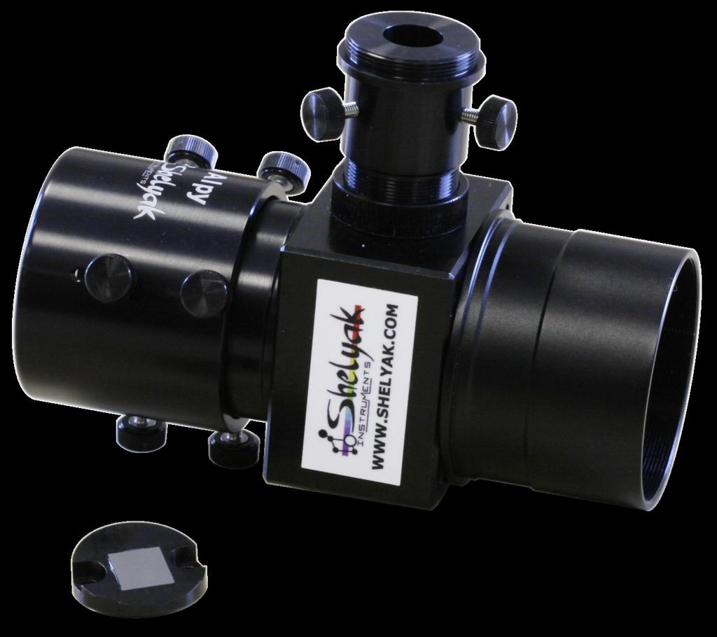
6 1 Discover your Alpy guiding module 1.1 Out of the box When you receive your Alpy guiding module, you ll find in the box the following parts: The Alpy guiding module itself, The mirror slit, 1.3 Alpy guiding principle 1.2 Alpy guiding specifications Table 1.1 gives detailed specifications of Alpy guiding. Figure 1.1 shows all dimensions. Mechanical interfaces The Alpy guiding module has several standard interfaces. You can use them to adapt it to your configuration. The main cube contains two T-mount threads (M42 x 0.75mm), one for attaching the spectroscope, the other one towards the telescope. The guider external body also has a T-mount thread. The CCD guiding port is a C-mount thread (1, 32 threads/inch): The principle of the Alpy guiding module is described in the figure below. The light beam coming from the star (collected by your telescope, on the axis) is focused on the slit plane of the spectroscope. After going through the slit, it continues towards the spectroscope. Another light beam, not exactly on the axis is reflected by the slit (manufactured with a mirror surface) at an angle towards the guiding mirror. The guiding mirror sends it towards the guiding optics, perpendicularly to the telescope axis, and finally to the guiding CCD: The guiding optics consist of two achromat doublets which transfer the slit plane image to the guiding CCD. 4
7 CHAPTER 1. DISCOVER YOUR ALPY GUIDING MODULE Feature Value Unit Comment Dimensions 90x65x75 mm see fig. 1.1 below Weight 260 g without guiding CCD camera F-ratio for guiding optics 1:1 - Guiding camera mount C-mount - Backfocus 17.5mm, can be extended to CS-mount (12.5mm) with an optional extender Guiding CCD max size 9,5 x 7,5 mm same as field size in focus plane Slit width 23 µm mirror slit Slit length 3 mm Table 1.1: Alpy guiding specifications Figure 1.1: Alpy guiding dimensions 5


8 Alpy guiding - User guide In the CCD image, you can then see the telescope field, and the slit (black line in the image below) Field of view calculation As a result, all the light which passes through the slit is spread out and analyzed by the spectroscope and all the light outside the slit is sent to the guiding CCD. In ideal conditions, when the telescope is aligned on the star, you should not see it any more in the guiding image. But in practise, you ll always see some of the light - it is almost impossible to send 100% of the starlight through the slit. It is sometime useful to calulate the Field Of View (FOV) of your guiding system. It depends not only on the Alpy guiding module optics, but also on your telescope focal length. The useable area of the guiding slit is 9,5 x 7.5 mm. If the guiding CCD is bigger than this size, the size of the slit limits the FOV (this is the max FOV). If the CCD is smaller, then this limits the FOV. In that case,use the CCD dimension instead of the mirror slit dimension. When looking at the guiding image, the less light you can see in the guiding image, the more is sent to the spectroscope (this is only true if the camera gain and image visualization thresholds are constant). The slit plane is the key location of your instrument. This is the focal plane for three elements : the spectroscope, the guiding camera and the telescope. In practise, we always recommend tuning these elements in this order: 1.Spectroscope 2.Guiding image 3.Telescope (based on the guiding image) Mirror slit The Alpy 600 spectroscope is shipped with a standard slit. This slit is not reflective and cannot be used for guiding. For this reason, the Alpy guiding module is shipped with its own reflective slit. This is a 23µm slit - optimized for the Alpy 600. In most cases, the FOV is limited by the guiding CCD size. The max FOV for your telescope focal length (F) is: α = 2 arctan( h 2F ) where h is the size of the slit field. For instance, if your telescope has a focus length of 1280mm, max FOV width is α = 2 arctan( 9,5mm mm ) = 25, 5 Here is the max FOV (in arcmin) for typical telescope focal lengths (FL): 6
9 CHAPTER 1. DISCOVER YOUR ALPY GUIDING MODULE FL (mm) width height diagonal ,3 51,6 83, ,8 32, ,7 25,8 41, ,5 20,1 32, ,8 17,2 27, ,3 12,9 20, ,9 8,6 13, ,2 6,4 10,4 7


 of the")


10 2 Installing & tuning the Alpy guiding module 2.1 Mounting the mirror slit on the Alpy 600 Replace it by the guiding slit. There is no specific orientation: Remove the external body from the Alpy 600; it will not be used with the Alpy guiding module: The Alpy 600 spectroscope has a removable slit holder. Remove the two screws, then the holder: The nominal thickness (base to slit) of the standard and guider slit holders are identical (5mm). However, there is some manufacturing tolerance so you should check that the focus of the Alpy 600 is still correct (refer to the Alpy 600 user guide). From the spectroscope standpoint, the guided slit is the equivalent of the standard 25µm slit (except the width is 23µm with guiding module). Attach the Alpy 600 to the CCD camera, and tune the spectroscope (focus and orientation - refer to the Alpy 600 user guide). 8


: Assemble this part onto the Alpy")

11 CHAPTER 2. INSTALLING & TUNING THE ALPY GUIDING MODULE 2.2 Assembling the Alpy 600 and guiding module Remove the guider external body from the guiding module (loosen the six knurled thumb screws): Rotate the spectroscope in such a way that the slit mirror is towards the guiding mirror (in the images below, the 2 adapter has been removed for a better view): Assemble this part onto the Alpy 600 body - tighten firmly: Push the Alpy 600 fully into the guiding module, and gently tighten the six screws. Assemble the Alpy 600 on the guiding module. 9


: The Alpy")


12 Alpy guiding - User guide Pushing the spectroscope fully in as far as it will go ensures that the slit is at the right position in the guiding module. Depending on the backfocus of your camera, the position of the spectroscope in the guiding module can vary. The picture above is valuable for an Atik 314L+ only. Remove the optics from the guiding module (loosen the two knurled thumb screws): Re-assemble the guiding camera on the module (tighten a little bit the knurled thumb screws): The Alpy guiding module is ready for use! 2.3 Tuning the guiding camera Start your PC, and launch the image acquisition software (The screen copies in this document werere made with Audela). Take a short exposure of the guiding image. You should have something like this: Mount the guiding camera on the guiding port, and tighten it firmly (the Atik Titan camera below has a T- mount thread - we ve added a C-mount to T-mount adapter): The dark band in the image is the slit, still very unfocused. Loosen the knurled thumb screws to allow the guiding optics to be rotated and loosen the locking ring to allow focusing: 10


13 CHAPTER 2. INSTALLING & TUNING THE ALPY GUIDING MODULE Take continuous images while turning the guiding optics. Try to maintain the camera orientation during this operation to make the image easier to read (it is not comfortable if the image is turning continuously). The slit image should become more and more focused. Eventually you should see it very sharp, and horizontal: Tuning this angle is done by rotating the spectroscope. Slightly loosen the six knurled thumb screws around the external body and adjust while continuously taking images: Tighten gently the locking ring and the knurled thumb screws. Mirror orientation The slit mirror can rotate around the telescope axis. Optimally, the slit mirror plane must be perpendicular to the guiding module plane (this is the plane formed by the telescope axis and the guiding optics axis). If the slit plane is at an angle, the sky image is sent towards the guiding CCD with the same angle, and the image quality will be poor. Also, you can have significant vignetting: The optimal position is when the vignetting is minimal. When you ve found it, tighten firmly the six knurled thumb screws. 11


 axis, the image moves across the slit.")

14 Alpy guiding - User guide It is probable that the slit direction will have moved : rotate the guiding camera to put it back horizontal. If required, re-focus the slit image in this position. When you rotate the spectroscope, the spectrum remains horizontal in the main CCD camera, because the acquisition camera is firmly attached to the spectroscope. After all these operations have been done, tighten firmly all the screws and the locking ring. From now on, the guiding camera will always give you a focused and horizontal image of the slit plane. The orientation of the instrument on the telescope should be such that when you move the telescope along the Right Ascension (RA) axis, the image moves across the slit. This is only a question of comfort, but it is easier to center the star in the guiding image if the movements of the telescope are aligned with the axes of the guiding image. In some special cases, you may decide to orientate the slit in another direction. It might be the case, for instance, for an extended object: 2.4 Mounting the spectroscope on the telescope Assembling the Alpy spectroscope on the telescope is an easy part: simply put the 2 nosepiece in the eyepiece holder. Focusing the telescope Point the telescope towards an object at the horizon (tree, mountain...), and focus it until you see this object sharp in the guiding image. 12
.")


15 CHAPTER 2. INSTALLING & TUNING THE ALPY GUIDING MODULE slit in the image any more (it is black on a black background). The focus of the slit comes from the guiding camera tuning (which should have been done on the bench). The focus of the object comes from the telescope tuning. When the instrument is ready, both slit & object must be focused in the guiding image. During daylight, ensure that your finder is aligned with the telescope: it will be much easier to find your target during the night. When an object is in the middle of the guiding image, it must be in the center of your finder. One final point to check before the night arrives: note where the center of the slit is in the guiding image (pixel X, Y). When night arrives, you don t see the 13
, high in the sky. Align it precisely with the finder.")
16 3 Observing with Alpy guiding Night has arrived, and your installation is now ready for your first star observation. Cool down your guiding camera (if it is a cooled camera). guiding image. 3.1 Putting the star in the guiding field Point your telescope towards a bright star (magnitude 0 to 3, for instance), high in the sky. Align it precisely with the finder. Take continuous guiding images, with a short exposure time (1 second or less). In most cases, with a small telescope (200mm or less), a bright star saturates the guiding camera in less than one second. The star should appear in the guiding camera. Check the image is not saturated and adjust the exposure time if necessary. Depending on your setup, the star can be saturated even with the shortest possible exposure time of your guiding camera. In this case, look for a fainter star - in any case, the image must be not saturated for the next steps. 3.2 The star in the slit Starlight enters the Alpy 600 spectroscope only when star is in the slit. During the night, you cannot see directly the slit in the guiding image: both background and slit are black. If not, move the telescope around slightly. If you still cannot see it, you can unfocus the telescope and increase the exposure time. Unfocusing the star makes it bigger and easier to see in the guiding camera. When you have caught the star, center it in the guiding image and focus it properly. Check also where exactly the star is in your finder when centered in the 14

17 CHAPTER 3. OBSERVING WITH ALPY GUIDING However, when you move the telescope in such a way that the star crosses the slit, it disappears. When the starlight disappears from the guiding image, it goes through the spectroscope. 3.3 More light in the spectroscope In general, astronomical targets are very faint, and you must maximise the quantity of light entering the spectroscope to improve the quality of your spectrum. A good spectrum is not only a spectrum with the right resolution, but also with a good Signal / Noise Ratio (SNR) for a given exposure time. It is key to understand that it is very easy to lose 90% or more of the light at the slit entrance! There are three ways to lose light at slit level: bad focus, star not exactly centered in the slit, poor guiding. Bad focus If the telescope is not precisely focused, the star image can be much bigger than the slit. In this case, only part of the starlight enters the spectroscope and the SNR is severely affected: In most cases, there will be always some remaining light in the guiding image. Only very faint objects will totally disappear. When the star is in the slit, you can take spectra with the Alpy 600 camera (refer to the Alpy 600 user guide). For a bright star (magnitude < 2), it should be saturated in few seconds. As soon as you can see your first spectrum, you can go to the next section. 15
.")
, the slit image is around 3 pixels wide. If we make an error of 1 pixel, it can affect about 30% of the light.")
18 Alpy guiding - User guide Star not exacltly centered in the slit The star image depends on your sky s seeing (quality), and on your telescope focal length. In most cases, the image size is of same order as the slit size (23µm). The alignment between star image and slit must be precise with only a few µm tolerance, to ensure that maximum light enters the spectroscope. With the configuration used in the document (Atik Titan camera), the slit image is around 3 pixels wide. If we make an error of 1 pixel, it can affect about 30% of the light. Poor guiding effect If the telescope mount alignment is not perfect (it is never perfect...), the star will move slightly in the guiding image. Then, it will probably leave the slit and again you ll reduce the level of light entering the spectroscope. This effect may not be significant for bright objects, because exposure times are short. But as soon as you go for fainter objects, guiding becomes critical. Guiding quality strongly depends on your mount tracking quality and on your guiding parameters. Guiding can be done manually - the observer looks continuously at the guiding image and corrects the telescope position when needed - but you will significantly improve the observation by working with auto-guiding - where the computer does the job, analyzing the image and correcting the telescope position. Auto-guiding is controlled by some parameters (correction thresholds, moving speed), and these parameters must be properly setup for your exact configuration. There is no general rule for this setup - it depends mainly on parameters like mount alignment, telescope tracking, wind, seeing. Global effect The three effects above are cumulative. If you loose 30% of the light because of focus, 30% because of centering and 30% because of tracking, at the end you ll lose about 66% of the light (0,7 x 0,7 x 0,7 = 0,34)! With the experience, you ll get these three effects under control. Just keep in mind that the difference between a poor and a good spectrum often comes from this point. Here are some keys to improve the SNR of your spectra: If the light level at slit is not under control, there will be a significant variation from one spectrum to another. Make a series of spectra, and measure the light level from one image to the next. If it is only few percent, you re fine. But if the variation is above 10%, it means that something is unstable in your setup. It can be a known source (wind or seeing for example), check what can be improved on your instrument. Compare your results with others. You will easily find in the forums people with a similar setup to yours. You should get similar results (SNR). Never hesitate to compare your results: our experience shows this is the best way to make significant progress. As explained above, when light enters the spectroscope, it disappears from the guiding image. This is true for all three effects (focus, centering, tracking). Then, if your star disappears, it definitely means that your setup is under control. It is important to be able to observe the disappearence of the star: tune the guiding image thresholds in such a way that image is not saturated. Saturation will greatly reduce the change in light level when star is in the slit. 16
19 CHAPTER 3. OBSERVING WITH ALPY GUIDING The less light remains in the guiding image, the more light enters the spectroscope and the better is the spectrum. 3.4 Put the star (always) in the center of the slit Here is another tip to improve your observations: always put the star at the same position in the slit, preferably right in the middle - this is the closest point to the instrument axis. By doing this, you will always use your instrument the same way, where the optical performance is best. Repeatablity is a key for quality. For this, auto-guiding can also help: if you keep the autoguiding target at the same position, the computer will do the job for you. In the image below, Autoguiding is activated in Audela, and the star remains at the same position X-Y: guiding), vs the telescope. Don t rotate the guiding camera, or the Alpy 600 camera - this will change the result, but not the way you want. Rotating the guiding camera will rotate the guiding image, but not the slit direction in the field image, Rotating the Alpy 600 camera will keep the spectrum unchanged... but it will no longer be horizontal. Rotating the Alpy 600 in the guiding module means that the field image will no longer be visible in the guiding image. 3.6 Conclusion You re now ready for high quality observations. Making good observations is not that difficult, but requires combining several elements. This document has described how to gett as much light as possible into the spectroscope. The Alpy 600 user guide explains how to proceed to get the best from this light. With experience, you ll go to fainter and fainter objects. Of course, the higher you go in magnitude, the more discoveries you have to make. This is really a never ending story. 3.5 Extended objects So far, only point-like objects (stars) have been considered. Of course, there are some astronomical objects which are extended : nebulae, galaxies, comets... Observing these objects is easier than stars, because of their surface area. You just need to keep in mind that only the light entering the slit will be analyzed by the spectroscope. In some cases, you may want to orientate the slit, to adapt it to your target. The rotation must be done with the whole Alpy instrument (Alpy Alpy 17
Whoppshel spectroscope Assembling the instrument
 Whoppshel spectroscope Assembling the instrument Rev Date Qui 0.1 29/12/2015 F. Cochard First revision, during test with O. Garde 0.2 06/01/2016 F. Cochard Text completion. 0.3 29/02/2016 F. Cochard Add
SYNGUIDER USER'S MANUAL
 SYNGUIDER USER'S MANUAL GETTING STARTED PREPARING THE SYNGUIDER BASIC OPERATIONS OPERATION UNDER THE NIGHT SKY SPECIFICATIONS 1 3 4 9 15 060613V1 Thank you for choosing the SynGuider. The SynGuider can
SIPS instructions for installation and use
 SIPS instructions for installation and use Introduction Thank you for purchasing the Starlight Integrated Paracorr System (referred to as SIPS hereafter), which incorporates the best focuser on the market
PlaneWave CDK Telescope Instructions. Setting the spacing and collimation for the CDK14/17/20/24
 PlaneWave CDK Telescope Instructions Setting the spacing and collimation for the CDK14/17/20/24 Collimation and Secondary Spacing Procedure The CDK optical design has four optical elements shown in Figure
First steps with a Slit Spectroscope
 First steps with a Slit Spectroscope Ken M Harrison September 2012 Ok, you ve taken the quantum leap and moved into your first slit spectroscope. Your initial experiences may have been with a grating (Star
Presented by Jerry Hubbell Lake of the Woods Observatory (MPC I24) President, Rappahannock Astronomy Club
 President, Rappahannock Astronomy Club") Presented by Jerry Hubbell Lake of the Woods Observatory (MPC I24) President, Rappahannock Astronomy Club ENGINEERING A FIBER-FED FED SPECTROMETER FOR ASTRONOMICAL USE Objectives Discuss the engineering
Presented by Jerry Hubbell Lake of the Woods Observatory (MPC I24) President, Rappahannock Astronomy Club ENGINEERING A FIBER-FED FED SPECTROMETER FOR ASTRONOMICAL USE Objectives Discuss the engineering
Astrophotography. An intro to night sky photography
 Astrophotography An intro to night sky photography Agenda Hardware Some myths exposed Image Acquisition Calibration Hardware Cameras, Lenses and Mounts Cameras for Astro-imaging Point and Shoot Limited
ECEN 4606, UNDERGRADUATE OPTICS LAB
 ECEN 4606, UNDERGRADUATE OPTICS LAB Lab 2: Imaging 1 the Telescope Original Version: Prof. McLeod SUMMARY: In this lab you will become familiar with the use of one or more lenses to create images of distant
Installation Instructions FW8S-STXL / FW8G-STXL Filter Wheel
 Installation Instructions FW8S-STXL / FW8G-STXL Filter Wheel SBIG Astronomical Instruments, A Division of Diffraction Limited. 59 Grenfell Crescent, Unit B, Ottawa, ON Canada, k2g 0G3 Tel: 613.225.2732
Supplementary Materials
 Supplementary Materials In the supplementary materials of this paper we discuss some practical consideration for alignment of optical components to help unexperienced users to achieve a high performance
Demetra User documentation DC0029A
 Demetra User documentation DC0029A Rev Date Who What 1.0 25/09/2017 F. Cochard First version (corrections from T. Rodda) Table of content 1 2 3 4 5 Introduction...2 Requirements...3 Installation...3 General
UV/Optical/IR Astronomy Part 2: Spectroscopy
 UV/Optical/IR Astronomy Part 2: Spectroscopy Introduction We now turn to spectroscopy. Much of what you need to know about this is the same as for imaging I ll concentrate on the differences. Slicing the
Hubble Optics CDK 17 Collimation Instructions 03/27/2012 Hubble Optics
 Hubble Optics CDK 17 Collimation Instructions 03/27/2012 Hubble Optics 1: CDK17 Specification: System Effective Focal Length: 2894.7 mm, (this might be slightly different for different set of optics) Figure
TVGuider astronomical telescope autoguider
 TVGuider astronomical telescope autoguider Components Sturdy aluminium case containing the electronics Sensitive black and white camera All connection cables Basic function A star image is captured with
Problems with filters can have the strangest causes
 Problems with filters can have the strangest causes If you switch from simple astrophotography to more difficult fields of activity and start working with different filters, correctors and systems, you
Improving the Collection Efficiency of Raman Scattering
 PERFORMANCE Unparalleled signal-to-noise ratio with diffraction-limited spectral and imaging resolution Deep-cooled CCD with excelon sensor technology Aberration-free optical design for uniform high resolution
Astroimaging Setup and Operation. S. Douglas Holland
 Outline: 1. Mount 2. Telescope 3. Cameras 4. Balance Mount 5. Acclimation 6. Cabling & Computer 7. Polar Alignment 8. CWD Position 9. 4 Star Align 10. Camera Control Software 11. Focus 12. Install Guide
Chapter 8. The Telescope. 8.1 Purpose. 8.2 Introduction A Brief History of the Early Telescope
 Chapter 8 The Telescope 8.1 Purpose In this lab, you will measure the focal lengths of two lenses and use them to construct a simple telescope which inverts the image like the one developed by Johannes
PHYS 3153 Methods of Experimental Physics II O2. Applications of Interferometry
 Purpose PHYS 3153 Methods of Experimental Physics II O2. Applications of Interferometry In this experiment, you will study the principles and applications of interferometry. Equipment and components PASCO
Introducing Celestron s EdgeHD Optical System
 Introducing Celestron s EdgeHD Optical System See the Universe in HD EdgeHD is an Aplanatic Schmidt telescope designed to produce aberration free images across a wide visual and photographic field of view.
Eric B. Burgh University of Wisconsin. 1. Scope
 Southern African Large Telescope Prime Focus Imaging Spectrograph Optical Integration and Testing Plan Document Number: SALT-3160BP0001 Revision 5.0 2007 July 3 Eric B. Burgh University of Wisconsin 1.
A Stony Brook Student s Guide to Using CCDSoft By Stephanie Zajac Last Updated: 3 February 2012
 A Stony Brook Student s Guide to Using CCDSoft By Stephanie Zajac Last Updated: 3 February 2012 This document is meant to serve as a quick start guide to using CCDSoft to take data using the Mt. Stony
FLAMINGOS at the KPNO 2.1-m
 FLAMINGOS at the KPNO 2.1-m Telescope Console Control Panels & GUIs used for Guiding Nick Raines & Richard Elston Version 0.1, 2003 October 21 FLAMINGOS at the 2.1-m: Guider Controls Page 1 of 10 Introduction
Reference and User Manual May, 2015 revision - 3
 Reference and User Manual May, 2015 revision - 3 Innovations Foresight 2015 - Powered by Alcor System 1 For any improvement and suggestions, please contact customerservice@innovationsforesight.com Some
Introduction. Imaging and Processing Overview -Equipment and Software
 Introduction Modern observing and imaging techniques, with automated goto mounts and CCD (charge-coupled device) cameras, http://en.wikipedia.org/wiki/charge-coupled_device allow detailed observation and
Basic Optics System OS-8515C
 40 50 30 60 20 70 10 80 0 90 80 10 20 70 T 30 60 40 50 50 40 60 30 70 20 80 90 90 80 BASIC OPTICS RAY TABLE 10 0 10 70 20 60 50 40 30 Instruction Manual with Experiment Guide and Teachers Notes 012-09900B
AG Optical Systems. Newtonian Astrograph Manual Version AG Optical Systems
 AG Optical Systems Newtonian Astrograph Manual Version 2 2012 Table of Contents 1. Introduction 2. System Specifications 3. Initial Assembly 4. Collimation 5. Care and Cleaning 6. Cooling Fan Operation
Orion StarShoot Autoguider PRO
 Orion StarShoot Autoguider PRO #52031 Providing Exceptional Consumer Optical Products Since 1975 Customer Support: www.oriontelescopes.com/contactus Corporate Offices: 89 Hangar Way, Watsonville CA 95076
RPMSP Series Installation Guide
 RPMSP Series Installation Guide Contents 1. Overview... page 1 2. Unpacking the Projector...2 3. Projector Configuration...2 4. Projector Throw Distance and Mounting...9 5. Projection Lens Focus...9 6.
UNIVERSITY OF HAWAII Institute for Astronomy. f/31 High Angular Resolution Imaging Spectrograph HARIS USER MANUAL update June 10, 1997
 UNIVERSITY OF HAWAII Institute for Astronomy f/31 High Angular Resolution Imaging Spectrograph HARIS USER MANUAL update June 10, 1997 To print more copies of this document, type: dvi2ps 88inch/mkoman/haris/haris
The only coma-corrector for Newtonian telescopes which does not increase the focal length. An f/4 Newton stays an f/4 Newton! Properties of the MPCC:
 MPCC Mark III Manual Photographic version (for CCD & DSLR): #2458400A V-1 Visual Multi Purpose Coma Corrector Mark III for visual and photographic use #2458403 The only coma-corrector for Newtonian telescopes
Getting started with Digital Astrophotography - Part II Rodger King - Dec 2016
 Getting started with Digital Astrophotography - Part II Rodger King - Dec 2016 RECAP Getting started with Digital Astrophotography - Part I Rodger King - May 2016 Visual Astronomy Equipment Telescope Tripod
Using a Howie Glatter Laser for Collimation of the Altair Deepfield RC
 Using a Howie Glatter Laser for Collimation of the Altair Deepfield RC Background Collimating a Richey Cretien scope is fundamentally different to collimating a Newtonian or SCT. For optimum performance,
GPI INSTRUMENT PAGES
 GPI INSTRUMENT PAGES This document presents a snapshot of the GPI Instrument web pages as of the date of the call for letters of intent. Please consult the GPI web pages themselves for up to the minute
Adaptive Coronagraphy Using a Digital Micromirror Array
 Adaptive Coronagraphy Using a Digital Micromirror Array Oregon State University Department of Physics by Brad Hermens Advisor: Dr. William Hetherington June 6, 2014 Abstract Coronagraphs have been used
The 0.84 m Telescope OAN/SPM - BC, Mexico
 The 0.84 m Telescope OAN/SPM - BC, Mexico Readout error CCD zero-level (bias) ramping CCD bias frame banding Shutter failure Significant dark current Image malting Focus frame taken during twilight IR
 www.cairn-research.co.uk Free Phone: 08453301267 (UK only) Tel: +44 (0) 1795590140 Fax: +44 (0) 1795594510 Important Information Please Read Before Installing and Operating Your Optosplit II For maximum
Opto Engineering S.r.l.
 TUTORIAL #1 Telecentric Lenses: basic information and working principles On line dimensional control is one of the most challenging and difficult applications of vision systems. On the other hand, besides
Cerro Tololo Inter-American Observatory. CHIRON manual. A. Tokovinin Version 2. May 25, 2011 (manual.pdf)
") Cerro Tololo Inter-American Observatory CHIRON manual A. Tokovinin Version 2. May 25, 2011 (manual.pdf) 1 1 Overview Calibration lamps Quartz, Th Ar Fiber Prism Starlight GAM mirror Fiber Viewer FEM Guider
Cerro Tololo Inter-American Observatory CHIRON manual A. Tokovinin Version 2. May 25, 2011 (manual.pdf) 1 1 Overview Calibration lamps Quartz, Th Ar Fiber Prism Starlight GAM mirror Fiber Viewer FEM Guider
Guide to Processing Spectra Using the BASS Software
 British Astronomical Association Supporting amateur astronomers since 1890 Guide to Processing Spectra Using the BASS Software Andrew Wilson 04 June 2017 Applicable to BASS Project Version 1.9.7 by John
AgilEye Manual Version 2.0 February 28, 2007
 AgilEye Manual Version 2.0 February 28, 2007 1717 Louisiana NE Suite 202 Albuquerque, NM 87110 (505) 268-4742 support@agiloptics.com 2 (505) 268-4742 v. 2.0 February 07, 2007 3 Introduction AgilEye Wavefront
The techniques covered so far -- visual focusing, and
 Section 4: Aids to Focusing The techniques covered so far -- visual focusing, and focusing using numeric data from the software -- can work and work well. But a variety of variables, including everything
Using the USB2.0 camera and guider interface
 Using the USB2.0 camera and guider interface The USB2.0 interface is an updated replacement for the original Starlight Xpress USB1.1 unit, released in 2001. Its main function is to provide a USB2 compatible
Instruction Manual for HyperScan Spectrometer
 August 2006 Version 1.1 Table of Contents Section Page 1 Hardware... 1 2 Mounting Procedure... 2 3 CCD Alignment... 6 4 Software... 7 5 Wiring Diagram... 19 1 HARDWARE While it is not necessary to have
ADVANCED OPTICS LAB -ECEN Basic Skills Lab
 ADVANCED OPTICS LAB -ECEN 5606 Basic Skills Lab Dr. Steve Cundiff and Edward McKenna, 1/15/04 Revised KW 1/15/06, 1/8/10 Revised CC and RZ 01/17/14 The goal of this lab is to provide you with practice
APPENDIX D: ANALYZING ASTRONOMICAL IMAGES WITH MAXIM DL
 APPENDIX D: ANALYZING ASTRONOMICAL IMAGES WITH MAXIM DL Written by T.Jaeger INTRODUCTION Early astronomers relied on handmade sketches to record their observations (see Galileo s sketches of Jupiter s
"Internet Telescope" Performance Requirements
 "Internet Telescope" Performance Requirements by Dr. Frank Melsheimer DFM Engineering, Inc. 1035 Delaware Avenue Longmont, Colorado 80501 phone 303-678-8143 fax 303-772-9411 www.dfmengineering.com Table
Handbook for the Starlight Xpress AO unit Issue 1 21/8/2005 Handbook for the Starlight Xpress SXV-AO unit
 Handbook for the Starlight Xpress SXV-AO unit Thank you for purchasing an SXV-AO active optics unit. This device should give you much improved guiding accuracy with almost any telescope and mount. Please
HOW TO TAKE GREAT IMAGES John Smith February 23, 2005
 HOW TO TAKE GREAT IMAGES John Smith February 23, 2005 The allure of taking pictures of objects in the night sky is a powerful attraction to many amateur astronomers. Whatever the equipment base, there
OPTICAL BENCH - simple type
 GENERAL DESCRIPTION: OPTICAL BENCH - simple type Cat: HL2240-001 Complete with Hodson Light Box. Cat: HL2241-001 Not including Hodson Light Box The IEC Optical Bench system is designed to be used with
Observational Astronomy
 Observational Astronomy Instruments The telescope- instruments combination forms a tightly coupled system: Telescope = collecting photons and forming an image Instruments = registering and analyzing the
Luna 0.4B user s manual.
 Luna 0.4B user s manual. You have just purchased a Luna Camera, thank you very much for choosing a Lunático product. Lunático Astronomía hopes the camera will fulfil your expectations. Manual Luna 0.4
Operating the CCD Camera
 Operating the CCD Camera 1995 Edition Incorporates ccd software for disk storage This eliminates problems with cc200 software 1 Setting Up Very little setup is required; the camera and its electronics
Sabeeh Irfan Ahmad, Physlab, 23 July 2016
 Horiba ihr550 Spectrometer QuickInstallation and Operation Guide Sabeeh Irfan Ahmad, Physlab, 23 July 2016 The Horiba ihr550 is an imaging spectrometer that can be used both as a spectrograph and as a
Phase-2 Preparation Tool
 Gran Telescopio Canarias Phase-2 Preparation Tool Valid from period 2014A Updated: 5 December 2013 1 Contents 1. The GTC Phase-2 System... 3 1.1. Introduction... 3 1.2. Logging in... 3 2. Defining an observing
STEM Spectrum Imaging Tutorial
 STEM Spectrum Imaging Tutorial Gatan, Inc. 5933 Coronado Lane, Pleasanton, CA 94588 Tel: (925) 463-0200 Fax: (925) 463-0204 April 2001 Contents 1 Introduction 1.1 What is Spectrum Imaging? 2 Hardware 3
Multi-Purpose Computerized Mount. Instruction Manual
 Multi-Purpose Computerized Mount Instruction Manual Table of Contents Introduction... 4 Warning... 4 Assembly... 5 Assembling the AllView Mount... 5 Tripod and Mount Setup... 5 Assembling and Installing
Please do not hesitate to contact us if you have any questions or issues during installation or operation
 OPTOSPLIT II Manual BYPASS This guide details initial set up and installation of your OptoSplit II Bypass (BP) image splitter. Each unit is serial numbered, calibrated and QC d prior to delivery, therefore
1.6 Beam Wander vs. Image Jitter
 8 Chapter 1 1.6 Beam Wander vs. Image Jitter It is common at this point to look at beam wander and image jitter and ask what differentiates them. Consider a cooperative optical communication system that
Phase-2 Preparation Tool
 Gran Telescopio Canarias Phase-2 Preparation Tool Valid from period 2012A Updated: 6 March 2012 1 Contents 1. The GTC Phase-2 System... 3 1.1. Introduction... 3 1.2. Logging in... 3 2. Defining an observing
The Wonderful World of Amateur Digital Microscopy. "How To Get Your Astrophotography Fix During Times of Poor Weather"
 The Wonderful World of Amateur Digital Microscopy or "How To Get Your Astrophotography Fix During Times of Poor Weather" Ever wonder what is inside your average coconut? by Mark Estes Click to email author
Imaging for the Everyone: A review of the Meade DeepSkyImager By Stephen P. Hamilton
 Imaging for the Everyone: A review of the Meade DeepSkyImager By Stephen P. Hamilton Like so many amateur astronomers, I was captivated by the beautiful images of deep space objects that I would see in
Alignment of the camera
 Related topics Detector Alignment, Rotation axis, tilt, Principle Alignment of the detector and the rotation stage is very important to get optimal quality images of a CT scan. In this experiment, the
ECEN. Spectroscopy. Lab 8. copy. constituents HOMEWORK PR. Figure. 1. Layout of. of the
 ECEN 4606 Lab 8 Spectroscopy SUMMARY: ROBLEM 1: Pedrotti 3 12-10. In this lab, you will design, build and test an optical spectrum analyzer and use it for both absorption and emission spectroscopy. The
Tools Needed 3/32 Allen Wrench which is located in your accessory kit Masking Tape
 Beam Alignment Overview Proper alignment of the beam is an important part of laser preventive maintenance. If the beam is out of alignment it is possible to lose power on the table, which will yield poor
User Manual. Digital Compound Binocular LED Microscope. MicroscopeNet.com
 User Manual Digital Compound Binocular LED Microscope Model MD82ES10 MicroscopeNet.com Table of Contents i. Caution... 1 ii. Care and Maintenance... 2 1. Components Illustration... 3 2. Installation...
machines 608 Trestle Point Sanford, FL Phone Fax
 Alignment for BOSSLASER machines 608 Trestle Point Sanford, FL 32771 Phone 888-652-1555 Fax 407-878-0880 www.bosslaser.com Table of Contents Four Corner Test. Error! Bookmark not defined. Vertical Alignment...
NexImage USER S MANUAL. Model # 93708, # # 95518, # ENGLISH
 NexImage USER S MANUAL Model # 93708, # 93711 # 95518, # 95519 ENGLISH Congratulations on your purchase of the Celestron NexImage Solar System imaging camera. Your NexImage camera comes with the following:
Optics and Telescopes
 Optics and Telescopes Properties of Light Law of Reflection - reflection Angle of Incidence = Angle of Law of Refraction - Light beam is bent towards the normal when passing into a medium of higher Index
Astrophotography. Playing with your digital SLR camera in the dark
 Astrophotography Playing with your digital SLR camera in the dark Lots of objects to photograph in the night sky Moon - Bright, pretty big, lots of detail, not much color Planets - Fairly bright, very
Ribcage Installation. Part 2 - Assembly. Back-Bone V1.06
 Ribcage Installation Part 2 - Assembly Back-Bone V1.06 Contents Section 1 Before You Get Started... 2 Included With Your Kit:... 2 Figure: A... 3 CAUTION!... 4 Note:... 4 Tools Required... 5 Section 2:
VATTSpec Instructions Rev. 10/23/2015
 VATTSpec Instructions Rev. 10/23/2015 Introduction VATTSpec is a medium resolution CCD range spectrograph with a skinny chip having excellent cosmetics. Its UA ITL chip, Serial Number 8228, has a gain
CCD User s Guide SBIG ST7E CCD camera and Macintosh ibook control computer with Meade flip mirror assembly mounted on LX200
 Massachusetts Institute of Technology Department of Earth, Atmospheric, and Planetary Sciences Handout 8 /week of 2002 March 18 12.409 Hands-On Astronomy, Spring 2002 CCD User s Guide SBIG ST7E CCD camera
1. Description This section describes the procedures to install the GNIRS onto a side looking port on the Gemini 8M telescope.
 4.3 Instrument Installation & Removal 4.3.1. Installing Instrument on Side Looking Port 1. Description This section describes the procedures to install the GNIRS onto a side looking port on the Gemini
University of Wisconsin Chemistry 524 Spectroscopic Components *
 University of Wisconsin Chemistry 524 Spectroscopic Components * In journal articles, presentations, and textbooks, chemical instruments are often represented as block diagrams. These block diagrams highlight
OPTICS I LENSES AND IMAGES
 APAS Laboratory Optics I OPTICS I LENSES AND IMAGES If at first you don t succeed try, try again. Then give up- there s no sense in being foolish about it. -W.C. Fields SYNOPSIS: In Optics I you will learn
Handbook for the SX Spectrograph
 Handbook for the SX Spectrograph Issue 1, 1/2/16 Handbook for the SX Spectrograph Introduction: Spectroscopy of astronomical objects is a relatively unexplored field for many amateur observers, as truly
INSTRUCTION MANUAL FOR THE MODEL C OPTICAL TESTER
 INSTRUCTION MANUAL FOR THE MODEL C OPTICAL TESTER INSTRUCTION MANUAL FOR THE MODEL C OPTICAL TESTER Data Optics, Inc. (734) 483-8228 115 Holmes Road or (800) 321-9026 Ypsilanti, Michigan 48198-3020 Fax:
User Manual. 1. Item Checklist. 2. Quick Start Guide. - version 1.0 -
 1. Item Checklist Thank you for purchasing the LVI SmartGuider autoguiding camera! Upon receipt, please check that your package is complete and contains the following items: 1. Control handlepaddle ( Control
User Manual - version 1.0 -
 User Manual - version 1.0-1 1. Item Checklist Thank you for purchasing the LVI SmartGuider autoguiding camera! Upon receipt, please check that your package is complete and contains the following items:
Southern African Large Telescope. Prime Focus Imaging Spectrograph. Instrument Acceptance Testing Plan
 Southern African Large Telescope Prime Focus Imaging Spectrograph Instrument Acceptance Testing Plan Eric B. Burgh University of Wisconsin Document Number: SALT-3160AP0003 Revision 2.2 29 April 2004 1
erosita mirror calibration:
 erosita mirror calibration: First measurements and future concept PANTER instrument chamber set-up for XMM mirror calibration: 12 m length, 3.5 m diameter: 8m to focal plane instrumentation now: f = 1.6
CHARGE-COUPLED DEVICE (CCD)
") CHARGE-COUPLED DEVICE (CCD) Definition A charge-coupled device (CCD) is an analog shift register, enabling analog signals, usually light, manipulation - for example, conversion into a digital value that
CHARGE-COUPLED DEVICE (CCD) Definition A charge-coupled device (CCD) is an analog shift register, enabling analog signals, usually light, manipulation - for example, conversion into a digital value that
INTRODUCTION TO CCD IMAGING
 ASTR 1030 Astronomy Lab 85 Intro to CCD Imaging INTRODUCTION TO CCD IMAGING SYNOPSIS: In this lab we will learn about some of the advantages of CCD cameras for use in astronomy and how to process an image.
FRAUNHOFER AND FRESNEL DIFFRACTION IN ONE DIMENSION
 FRAUNHOFER AND FRESNEL DIFFRACTION IN ONE DIMENSION Revised November 15, 2017 INTRODUCTION The simplest and most commonly described examples of diffraction and interference from two-dimensional apertures
Be aware that there is no universal notation for the various quantities.
 Fourier Optics v2.4 Ray tracing is limited in its ability to describe optics because it ignores the wave properties of light. Diffraction is needed to explain image spatial resolution and contrast and
ML7520 ML7530 DIOPTER ADJUSTMENT RING BINOCULAR BODY, INCLINED 30. (a) Field Iris Control Lever. (c) Filter Slots EYEPIECES, KHW10X
 Field Iris Control Lever. (c) Filter Slots EYEPIECES, KHW10X") JAPAN DIOPTER ADJUSTMENT RING BINOCULAR BODY, INCLINED 30 (a) Field Iris Control Lever (c) Filter Slots EYEPIECES, KHW10X ANALYZER CONTROL LEVER (b) Aperture Iris Control Lever LIGHT SOURCE HOUSING VERTICAL
JAPAN DIOPTER ADJUSTMENT RING BINOCULAR BODY, INCLINED 30 (a) Field Iris Control Lever (c) Filter Slots EYEPIECES, KHW10X ANALYZER CONTROL LEVER (b) Aperture Iris Control Lever LIGHT SOURCE HOUSING VERTICAL
Single Photon Interference Katelynn Sharma and Garrett West University of Rochester, Institute of Optics, 275 Hutchison Rd. Rochester, NY 14627
 Single Photon Interference Katelynn Sharma and Garrett West University of Rochester, Institute of Optics, 275 Hutchison Rd. Rochester, NY 14627 Abstract: In studying the Mach-Zender interferometer and
Puntino. Shack-Hartmann wavefront sensor for optimizing telescopes. The software people for optics
 Puntino Shack-Hartmann wavefront sensor for optimizing telescopes 1 1. Optimize telescope performance with a powerful set of tools A finely tuned telescope is the key to obtaining deep, high-quality astronomical
Lab 10: Lenses & Telescopes
 Physics 2020, Fall 2010 Lab 8 page 1 of 6 Circle your lab day and time. Your name: Mon Tue Wed Thu Fri TA name: 8-10 10-12 12-2 2-4 4-6 INTRODUCTION Lab 10: Lenses & Telescopes In this experiment, you
Educational Spectrophotometer Accessory Kit and System OS-8537 and OS-8539
 GAIN 1 10 Instruction Manual with Experiment Guide and Teachers Notes 012-06575C *012-06575* Educational Spectrophotometer Accessory Kit and System OS-8537 and OS-8539 100 CI-6604A LIGHT SENSOR POLARIZER
Frame Calibration* CCD, Video & DSLR. * Also known as reduction
 Introduction to Basic Image Frame Calibration* CCD, Video & DSLR * Also known as reduction Simon Hanmer & Rob Lavoie (OAOG) November 8 th, 2013 INTRODUCTION Amateur astronomy has entered the digital «universe»
INSTRUCTION MANUAL # Providing Exceptional Consumer Optical Products Since Customer Support (800)
") INSTRUCTION MANUAL Orion StarShoot Deep Space Color Imaging Camera #52065 Providing Exceptional Consumer Optical Products Since 1975 Customer Support (800) 676-1343 E-mail: support@telescope.com Corporate
INSTRUCTION MANUAL Orion StarShoot Deep Space Color Imaging Camera #52065 Providing Exceptional Consumer Optical Products Since 1975 Customer Support (800) 676-1343 E-mail: support@telescope.com Corporate
Model ST-9XE CCD Imaging Camera SBIG ASTRONOMICAL INSTRUMENTS
 Model ST-9XE CCD Imaging Camera.. SBIG ASTRONOMICAL INSTRUMENTS 1... Model ST-9XE Dual CCD Self-Guiding Camera The ST-9XE is identical to the ST-7/8/10/2000 cameras with the exception of the imaging CCD.
Panosaurus Rex. May Please Visit To view the setup video for the Panosaurus Rex.
 Panosaurus Rex May 2009 Please Visit http://gregwired.com/pano/support.htm To view the setup video for the Panosaurus Rex. Note: There currently is no printed setup information available. This booklet
Hyperion. 16 f/7.3 Astrograph Operating Instructions
 Hyperion 16 f/7.3 Astrograph Operating Instructions Thank you for purchasing a Hyperion telescope. You now own the most state-of-the-art astrograph available. In addition to providing a large aberration-free
Photometry using CCDs
 Photometry using CCDs Signal-to-Noise Ratio (SNR) Instrumental & Standard Magnitudes Point Spread Function (PSF) Aperture Photometry & PSF Fitting Examples Some Old-Fashioned Photometers ! Arrangement
Sharpness, Resolution and Interpolation
 Sharpness, Resolution and Interpolation Introduction There are a lot of misconceptions about resolution, camera pixel count, interpolation and their effect on astronomical images. Some of the confusion
Very short introduction to light microscopy and digital imaging
 Very short introduction to light microscopy and digital imaging Hernan G. Garcia August 1, 2005 1 Light Microscopy Basics In this section we will briefly describe the basic principles of operation and
Some Aspects of Light Pollution in the Near Infrared
 Some Aspects of Light Pollution in the Near Infrared Željko Andreić 1 and Doroteja Andreić 2 1 Faculty of Mining, Geology and Petroleum Eng., University of Zagreb, Pierottijeva 6, 10 000 Zagreb, Croatia,