INSTRUCTION MANUAL FOR THE MODEL C OPTICAL TESTER
|
|
|
- Gillian Mathews
- 6 years ago
- Views:
Transcription
1 INSTRUCTION MANUAL FOR THE MODEL C OPTICAL TESTER
2 INSTRUCTION MANUAL FOR THE MODEL C OPTICAL TESTER Data Optics, Inc. (734) Holmes Road or (800) Ypsilanti, Michigan Fax: (734) Web site: sales@dataoptics.com Copyright 2003 by Data Optics, Inc. - i -
3 CONTENTS Page Principles of Operation Assembly Optical Testing Arrangements Lenses Spherical Mirrors Parabolic Mirrors Focal Length Determination Determining the Optical Axis of an Off-Axis Parabolic Mirrors Mirror Aberrations Lens Aberrations Spherical Aberration Coma Chromatic Aberration Model E Distortion Test Set-up Bibliography Appendix I - Determining the focal plane of a perfect lens Appendix II - Pattern Photography ii -
4 PRINCIPLES OF OPERATION When a lens (or mirror) is illuminated through a grating, as in Figure 1, with the grating near the focal plane F, then the eye, placed at P in the returning beam of light sees a number of dark lines which appear localized on the lens. Spherical Mirror F P (a) Plane Mirror / Lens Lens F P (b) Figure 1 In Figure 1, if the grating is behind the focal plane, then its image is an equal distance in front. Upon looking at the lens through the grating, all the rays passing through the grating image cannot reach the eye, as they are stopped by the opaque parts of the grating. As a result, a pattern of light and dark lines is seen. If the lens is well corrected, the shadow lines or fringes are straight, parallel, and equidistant. The distance separating them increases as the grating is moved nearer to the focal plane, at which point they disappear completely. In the case of a poor lens or mirror the fringes have a complex form, varying according to the position of the grating. The pattern covers the entire lens (or mirror) when testing optics having focal lengths greater than 3 to 4 inches. For shorter focal lengths, the examination may be limited to proportionately smaller portions of the lens
5 ASSEMBLY The Model C Optical Tester, as shipped in its standard configuration, consists of the following parts: 1. A head unit to which can be mounted any of three gratings (50, 100 and 200 line pairs per inch Ronchi rulings) in metal mounts. 2. A lamp holder, which screws into the bottom of the head unit. 3. A inch (12.7 mm) diameter precision stainless steel post, for hand-holding, mounting on an optical bench, or in a laboratory stand. This post screws into the bottom of the lamp holder. 4. Three #50 incandescent lamps, one installed plus two spares. 5. A universal power supply for providing power to the lamp from a 120 or 240 volt, Hz outlet. Several output voltages are available to vary the intensity of the light. The lamp is rated for 1,000 hours at 7.5 volts. The lamp may be operated at 9 volts to produce a brighter light; however, the life of the lamp will be significantly shortened. 6. A first surface mirror and a lens, for demonstrating the use of the tester. The mirror is plate glass quality and the lens has visible distortion for demonstration purposes. 7. A padded carrying case. 8. A copy of this Instruction Manual. The Optical Tester is shipped assembled, ready for immediate use, with the 50 line grating mounted in place. To interchange the gratings, it is only necessary to remove the two thumb nuts, and replace the grating mount with the one with the desired number of lines. Always install the grating mount so that the identifying number (line pairs per inch) on the mount is to the outside
6 OPTICAL TESTING ARRANGEMENTS The Optical Tester can be hand-held for a casual inspection of mirrors and lenses. However, for an accurate measurement of focal length or a critical analysis, it should be clamped in position, preferably with some mechanical adjustment for movement toward and away from the optical component being inspected. For this purpose, an adjustable laboratory stand of any kind can be used. Also good for this purpose is an inexpensive type of optical bench such as those used for instructional use. The particular optical arrangement depends on the type of lens or mirror being inspected, and the laboratory facilities available. A dark room is not necessary. The arrangements shown in Figure 1 can be arranged either vertically or horizontally. Lenses: With the Optical Tester are furnished a lens having a focal length of 7 to 9 inches and a first surface plane mirror 2" square. The lens and mirror are included to permit the user to familiarize himself with the method of using the Tester, and are not intended as optical test components. To examine the lens, the arrangement shown in Figure l(b) is used. The distance from the lens to the focal plane, F, should be approximately the focal length of the lens. Looking at the lens surface through the grating at the head of the Tester with the eye close to the grating holder, it will appear that the surface of the lens is illuminated. If the surface is not illuminated, it is because the grating is not on the optic axis or is not parallel to the lens surface. Moving the Tester around slightly will determine the proper position. Once this position is found, the Tester can be moved along the optic axis (taking care to keep it on the axis) to determine how the fringes crossing the illuminated surface increase or decrease in number on leaving or approaching the focal plane. The analysis of these fringes as pertaining to focal plane and aberrations is discussed in the sections entitled: Focal Length Determination and Aberrations. A caution in the selection of the correct size of grating: Use as coarse a grating as can be used to get the information desired. For instance, in examining the demonstration lens as above, the 50 lines per inch grating should be used. This grating will give the full information as to focal length, spherical aberration, and chromatic aberration for a lens of this quality. Using the finer gratings on this lens will result in a pattern far too complex for this component. The finer gratings, and especially the 200 lines per inch grating, should only be used in testing the highest quality optics. Likewise, for a more critical examination of quality optics, a better mirror or a silvered optical flat should be used. The mirror furnished has a surface accuracy of from 1/2 to 2 wavelengths of visible light
7 Spherical Mirrors: To test spherical mirrors, the apparatus is set up as in Figure 1(a). The Tester is located near the plane F. The distance from the mirror to the focal plane, F, in this case is the radius of curvature, or twice the focal length of the mirror. If this approximate value is not known, it can be determined by hand-holding the Tester in such a way that the mirror surface appears to be illuminated when viewed through the Tester grating. Then move the Tester toward or away from the mirror to the position of the least number of fringes in the pattern at which point the Tester is near the center of curvature of the mirror. Parabolic Mirrors: To test a parabolic mirror, the arrangement shown in Figure 2(a) should be used, where the distance of the focal plane, F, from the mirror is approximately the focal length. Here, as in the case of lenses, the choice of quality of the plane mirror M is governed by how critical the examination is to be. The plane mirror should have a 1" diameter hole through the center but if such a mirror is not available, the parabolic mirror can be tested in sections by using the arrangement in Figure 2(b). To test an off-axis parabolic mirror, the arrangement is that shown in Figure 2(c). Parabolic Mirror Plane Mirror F P F P (a) (b) Off-Axis Parabolic Mirror F P (c) Figure 2-4 -
8 FOCAL LENGTH DETERMINATION With the optics in proper alignment, parallel fringes will be seen when observing the lens or mirror surface through the grating at the head of the Optical Tester. The number of fringes decreases as the Tester approaches the focal plane F from either direction. The finer the grating, the more rapid is the decrease in fringes. Figure 3, page 6, shows the patterns obtained at the distances indicated inside and outside of the plane F for an 8 inch focal length spherical mirror with a 200 line per inch grating. On approaching F the fringes spread out rapidly and reveal the features which indicate the character of the optical surface. The interpretation of the pattern in terms of the optical surfaces is discussed in the next section. To accurately determine the location of plane F, one can have the Tester mounted on a linear adjustment, so that it can be moved smoothly through F to select the pattern shown in Figure 3(d). When the tester is at this position, the side of the grating closest to the optics is either at the focal point or center of curvature, depending on which optical setup is being used (Figures 1 or 2). When a more accurate determination of the plane F is desired, the Tester is moved away from F in the direction away from the optical surface until 3 to 10 fringes are visible across the surface. Then using the following relation, one can calculate the exact distance from the grating to the plane F. The derivation of this equation is given in Appendix I. x = nf where: 2DN x = the distance from grating to focal plane n = number of fringes across the mirror or lens F = approximate focal length or radius of curvature D = diameter of mirror or lens N = number of lines per inch in grating In the case of lenses having considerable chromatic aberration the fringes will vary in color across their width. This effect is somewhat disturbing in counting fringes, and can be eliminated by observing the pattern through a filter, such as a piece of colored cellophane or plastic. Also, when a lens has considerable spherical aberration (as in the demonstration lens) the fringe spacing varies across the lens. In this case no single focal plane exists for the lens, as the focal length is varying continually across the surface of the lens. The appearance of the pattern of such a lens when the Tester is at the focal plane of the central portion is shown in Figure 9, page 6. This photograph was taken through a Corning 5031 filter
")
 -0.")

")
 0.")

 (d)")


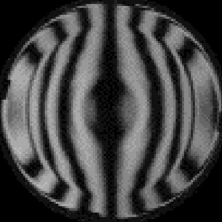
9 (a) " (b) " (c) " (d) 0.000" (e) 0.008" (f) 0.025" (g) 0.051" Figure 3 (a) (b) (c) (d) Figure 4 Figure 6 Figure 9-6 -
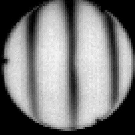
10 DETERMINING THE OPTICAL AXIS OF OFF-AXIS PARABOLIC MIRRORS Often off-axis parabolic mirrors are received from the fabricator without markings indicating the side of the mirror which is toward the optical axis. Also, even with such markings, only the plane containing the axis is defined, and it is still necessary to locate the axis. The position of the optical axis is easily determined by observing the pattern obtained with the Optical Tester. Only when the Tester is on the optical axis will the fringes be equally spaced and parallel to each other and to the lines in the grating when using an arrangement as in Figure 2(c). The resulting patterns for the Tester in the correct and other positions with respect to the axis can be seen from the patterns pictures in Figure 4, page 6. Figure 4(a) shows the pattern obtained with the Tester on the optical axis of a 30" focal length parabolic mirror cut 7 off-axis. This position is illustrated in Figure 5, with the Tester at A and the edge of the parabolic mirror closest to the optical axis at A'. Figure 4(b) shows the pattern when the Tester, parabolic mirror, and plane mirror are still in the correct plane, but the grating is located outside the optical axis (B in Figure 5). Off-Axis Parabolic Mirror Plane Mirror Figure 5 Moving the grating back to position A, and rotating the parabolic mirror 10 clockwise, the pattern shown in Figure 4(c) will be seen. In this case, the optical plane is rotated as shown dotted in Figure 5, and the grating is below the optic axis. If one continued to rotate the mirror to the 90 position, the optic axis would be as indicated by the dashed lines in Figure 5, and the pattern with the grating as A would appear as in Figure 4(d)
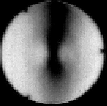
11 MIRROR ABERRATIONS As indicated previously, when the grating approaches the focal plane, the fringes spread out rapidly and reveal the features which indicate the quality of the optics under test. When a lens or mirror is of good optical quality, the fringes remain straight and parallel as they spread out, while those of poor quality give distorted patterns. The patterns received with mirrors are always colorless, because of the lack of chromatic aberration, but will give patterns describing the mirror surface. Figure 6, page 6, is the pattern of a 6 inch spherical mirror with an 8 inch focal length, photographed just outside the focal plane. It will be seen that there are three focal zones, indicated by the three sets of fringe spacing. In the inner zone, the fringes are spread further apart, thus indicating that the focus of this area is longer than the intermediate and outer zones. This can be demonstrated by moving the Tester gradually toward the mirror. On reaching the point where the fringes of the inner zone have disappeared, (the focal plane for this zone) it will be seen that the fringes in the other zones are still present, indicating that their focal plane is still further away. By continuing to move the Tester in, a point is reached where the fringes reappear in the inner zone but disappear in the outside zone, indicating its focal plane. Finally, by continuing to move the Tester in, the focal plane of the intermediate zone is reached. By measuring the distance which the Tester traveled in passing through these 3 zones, it was found that the maximum difference in the radius of curvature of the zones was about inches. A simpler method of determining the variation in radius of curvature over the surface of this mirror is to locate the Tester so that the fringes in the zone of least curvature (inner zone in this case) have disappeared. At this point, the grating is at the center of curvature of this zone. Then, by counting the fringes in the other zones and measuring the diameter of each zone, one can calculate the difference between their curvature and that of the central zone. The zone diameter is measured by placing a narrow ruler across the mirror surface while observing the pattern through the Tester. For example, in this case, when the Tester is at the position where the central zone fringes disappear, the number of fringes in the intermediate zone decrease to 7. Then, as the zone diameter is 5 inches, the difference in the radius of curvature, x = nf = 7 x 16 = DN 2 x 5 x 100 Here D is the zone diameter, rather than the diameter of the mirror. This intermediate zone is parabolic in shape, as indicated by the narrower spacing of the fringes toward - 8 -
12 the outside of the zone. The variation in the radius of curvature across this zone can be calculated by using the formula: x = F where m is the distance between fringes 2mN (center to center) The distance between the two inner fringes is 1.30 inches and the distance between the two outer fringes is 0.38 inches. Substituting these values in the above formula, one finds that the grating is displaced inches from the center of curvature of the inner portion and inches from the outer. The difference, 0.149, is the variation in radius of curvature across this intermediate zone. An aberration found often in spherical mirrors is present in the 8" focal length mirror used to obtain the patterns shown in Figure 3. This mirror has a center zone two inches in diameter whose radius of curvature is inches less than the rest of the mirror surface. This was determined from Figure 3(g), where the inner fringes are 1.34 inches apart and the outer fringes are 1.18 inches apart. Spherical Aberration: LENS ABERRATIONS Spherical aberration causes a blurring of the image of a point object placed anywhere along the optic axis. Since many of the lenses in optical instruments are used to focus parallel incident rays, such as a point object at a great distance, it is usual for comparison purposes to compute spherical aberration for parallel incident light (a) Figure 7 Figure 7(a) illustrates this special case, showing the focal points for parallel rays passing through various portions of the lens. The ray A comes to a focus at A', B at B', and C at C'. The distance from A' to C' is the measure of spherical aberration for this lens. In using the Tester, parallel incident rays are focused by the lens under test, but as the rays transverse the lens twice, the distance A' to C' is doubled, so therefore all measurements of spherical aberration in lenses with the Tester must be divided by 2 to abide by convention. The series of drawings (Figures 8(a), (b), and (c)) shows the affect on the patterns when moving the Tester along the optic axis through the points A', B', and C' of Figure 7(a) (b)
). This can be seen in Figure 9, page 6, which is a picture of the pattern of a simple lens, taken through a Corning 5031 filter to eliminate the effect of chromatic aberration.")

13 (a) (b) (c) Figure 8 Spherical aberration is identified by the manner in which the fringe spacing decreases to the outside of the lens when the Tester is at the focal plane of the center of the lens (Figure 7(a)). This can be seen in Figure 9, page 6, which is a picture of the pattern of a simple lens, taken through a Corning 5031 filter to eliminate the effect of chromatic aberration. Observing the pattern in the focal plane of the center of a lens, the amount of spherical aberration can be calculated by using the formula on page 10. By measuring the distance between fringes, the difference in focal length between each zone and the center zone can be determined. One can then plot a graph of this difference in focal length versus the radius of the various zones. This measure of spherical aberration is shown in Figure 7(b) for the lens pattern pictures in Figure 9. Figure 10 is a sketch of a pattern received from a lens partially corrected for spherical aberration. Coma: Figure 10 Coma is the aberration resulting when off-axis rays pass through an uncorrected lens. It is detected and measured with the Optical Tester in the same manner as spherical aberration, except that the lens is rotated slightly, so that the rays from the Tester transverse the lens at an angle of 2 to 5 degrees with the optic axis. This produces a pattern with an appearance such as sketched in Figure

14 Figure 11 Chromatic Aberration: A single lens forms a series of images, one for each color of light present in the beam, because of the change in refractive index with color. This is illustrated in Figure 12 for a point source of white light at infinity. Violet Green Red Figure 12 The presence of chromatic aberration in the demonstration lens is indicated by the color separation in the fringes. This aberration can be measured in the same manner as spherical aberration, by setting the Optical Tester in the focal plane of green light (indicated by a green spot in the center of the lens) and measuring the distance out to the red fringe. Then, by using the formula on page 8, one can calculate the distance to the focal plane of red light, which is a measure of longitudinal chromaticism between these two colors. In a lens uncorrected for spherical aberrations, this measurement is difficult to make, because the red fringe is partially covered by succeeding fringes
15 Model E Distortion Test Set-up To Align Suggested Set-up for MIL-SPEC Place the mirror mount and the 235 mm focal length, achromatic lens approximately in position. Keep the mirror as close as possible to the lens but still have room for the specimen. The lens must face towards the tester with the face that produces minimal aberration. The other face will show considerable spherical aberration in the tester. Trying the lens both ways without a sample in place will allow the proper face to be determined. Place your eye about 200 mm (8 inches) from the 235 mm focal length lens and sight through to the mirror mount. Adjust the mirror so that the reflected image (a circle outline) is centered in the lens diameter. The mirror should just about fill the lens. Place the lens tester on the rail about 200 mm (8 inches) from the lens. Adjust the tester vertically so that the maximum amount of illuminated area is showing. The image might not completely fill the lens especially along the bottom. Move the tester away from the lens. The illuminated area should completely fill the lens and the tester. Vertical lines should be seen. The lines will become spaced farther apart as the grating in the tester passes through the focal point of the lens. Move the tester to the position specified in the MIL-SPEC. Place the specimen between the mirror and the lens. Distortions in the specimen should now be observed
16 BIBLIOGRAPHY 1. M. L. Lenouvel: "Methode de Determination et de mesure des Aberrations des Systemes Optiques. " Revue d' Optique, Vol. 3, p , p (1924). 2. V. Ronchi: "Sur la nature interferentielle des franges d'ombre dans 1'essai des systemes optiques". Revue d'optique, Vol. 5, p (1926). 3. J. A. Anderson and R. W. Porter: "Rone hi's Method of Optical Testing". The Astrophysical Journal, 1929, p A. R. Kirkham: "The Ronchi Test for Mirrors". Amateur Telescope Making, Volume 1, p J. H. King: "A Quantitative Optical Test for Telescope Mirrors". Amateur Telescope Making, Volume 2, p Vasco Ronchi: "Forty Years of History of a Grating Interferometer". Applied Optics, Vol. 3, p. 437 (1964)
17 APPENDIX I Determining the focal plane of a perfect lens Consider the case where L is a perfect lens backed by a mirror as in Figure 1(b). T T L A A r R x x F Figure 13 If the grating T (Figure 13) is the distance x behind the focal plane, Then its image T' is formed a distance x ahead of the focus. The optic axis passes through the grating at the center of a transparent strip. The point A on the grating, on the axis of the lens, acts as a luminous source whose image A' is also on the axis and in the plane T'. The cone of rays having A' as the vertex and the lens as the base passes through the grating within a circle of radius r. Then by geometry: r = R or r = 2xR 2x (F-x) F-x But, when the grating is near the focal plane, x is small compared to F, and the above relation can be written: r = 2xR or x = rf F 2R But, the radius in inches of the circle of radius r is n/2n, where n is the number of dark fringes in the circle (or as observed across the face of the lens) and N is the
18 number of lines per inch in the grating. Also, 2R is equal to the aperture D of the lens. Substituting into the above equation, one gets: x = nf 2DN 1 Also, the number of fringes observed per inch, p, across the lens is equal to n/d, or the distance between fringes, m, is equal to D/n. So equation 1 can be written: and x = pf 2N 2 x = F 2mN 3 APPENDIX II Pattern Photography Photographic records of test patterns can be obtained either by use of a camera or by using a lens (such as the demonstration lens) in a darkroom. Holding the Optical Tester with a laboratory stand or in any other stable manner, adjust the Tester to give the pattern to be photographed. Then mount the camera with its lens close and centered in the grating opening and focus on the closest optical surface being tested. All the patterns pictured in this manual were photographed in a darkroom using a 4", f/0.1, simple lens. The lens is put in the eye position shown in Figure 1. The lens can have a focal length of from 2" to 8", depending on the focal length of the optics being tested and the size pattern desired. A ground glass is moved back and forth to find the plane of best focus on the pattern, and then replaced with a photographic plate, such as Process or Lantern Slide plates. Because of the long exposures involved (1/2 to 2 minutes), the light switch on the Tester can be used to control the time of exposure
Aberrations of a lens
 Aberrations of a lens 1. What are aberrations? A lens made of a uniform glass with spherical surfaces cannot form perfect images. Spherical aberration is a prominent image defect for a point source on
Ch 24. Geometric Optics
 text concept Ch 24. Geometric Optics Fig. 24 3 A point source of light P and its image P, in a plane mirror. Angle of incidence =angle of reflection. text. Fig. 24 4 The blue dashed line through object
CH. 23 Mirrors and Lenses HW# 6, 7, 9, 11, 13, 21, 25, 31, 33, 35
 CH. 23 Mirrors and Lenses HW# 6, 7, 9, 11, 13, 21, 25, 31, 33, 35 Mirrors Rays of light reflect off of mirrors, and where the reflected rays either intersect or appear to originate from, will be the location
PRINCIPLE PROCEDURE ACTIVITY. AIM To observe diffraction of light due to a thin slit.
 ACTIVITY 12 AIM To observe diffraction of light due to a thin slit. APPARATUS AND MATERIAL REQUIRED Two razor blades, one adhesive tape/cello-tape, source of light (electric bulb/ laser pencil), a piece
GEOMETRICAL OPTICS Practical 1. Part I. BASIC ELEMENTS AND METHODS FOR CHARACTERIZATION OF OPTICAL SYSTEMS
 GEOMETRICAL OPTICS Practical 1. Part I. BASIC ELEMENTS AND METHODS FOR CHARACTERIZATION OF OPTICAL SYSTEMS Equipment and accessories: an optical bench with a scale, an incandescent lamp, matte, a set of
Waves & Oscillations
 Physics 42200 Waves & Oscillations Lecture 33 Geometric Optics Spring 2013 Semester Matthew Jones Aberrations We have continued to make approximations: Paraxial rays Spherical lenses Index of refraction
Week IV: FIRST EXPERIMENTS WITH THE ADVANCED OPTICS SET
 Week IV: FIRST EXPERIMENTS WITH THE ADVANCED OPTICS SET The Advanced Optics set consists of (A) Incandescent Lamp (B) Laser (C) Optical Bench (with magnetic surface and metric scale) (D) Component Carriers
Laboratory 7: Properties of Lenses and Mirrors
 Laboratory 7: Properties of Lenses and Mirrors Converging and Diverging Lens Focal Lengths: A converging lens is thicker at the center than at the periphery and light from an object at infinity passes
Physics II. Chapter 23. Spring 2018
 Physics II Chapter 23 Spring 2018 IMPORTANT: Except for multiple-choice questions, you will receive no credit if you show only an answer, even if the answer is correct. Always show in the space on your
Mirrors and Lenses. Images can be formed by reflection from mirrors. Images can be formed by refraction through lenses.
 Mirrors and Lenses Images can be formed by reflection from mirrors. Images can be formed by refraction through lenses. Notation for Mirrors and Lenses The object distance is the distance from the object
This experiment is under development and thus we appreciate any and all comments as we design an interesting and achievable set of goals.
 Experiment 7 Geometrical Optics You will be introduced to ray optics and image formation in this experiment. We will use the optical rail, lenses, and the camera body to quantify image formation and magnification;
Light sources can be natural or artificial (man-made)
") Light The Sun is our major source of light Light sources can be natural or artificial (man-made) People and insects do not see the same type of light - people see visible light - insects see ultraviolet
Light The Sun is our major source of light Light sources can be natural or artificial (man-made) People and insects do not see the same type of light - people see visible light - insects see ultraviolet
Collimation Tester Instructions
 Description Use shear-plate collimation testers to examine and adjust the collimation of laser light, or to measure the wavefront curvature and divergence/convergence magnitude of large-radius optical
Basic Optics System OS-8515C
 40 50 30 60 20 70 10 80 0 90 80 10 20 70 T 30 60 40 50 50 40 60 30 70 20 80 90 90 80 BASIC OPTICS RAY TABLE 10 0 10 70 20 60 50 40 30 Instruction Manual with Experiment Guide and Teachers Notes 012-09900B
COURSE NAME: PHOTOGRAPHY AND AUDIO VISUAL PRODUCTION (VOCATIONAL) FOR UNDER GRADUATE (FIRST YEAR)
 FOR UNDER GRADUATE (FIRST YEAR)") COURSE NAME: PHOTOGRAPHY AND AUDIO VISUAL PRODUCTION (VOCATIONAL) FOR UNDER GRADUATE (FIRST YEAR) PAPER TITLE: BASIC PHOTOGRAPHIC UNIT - 3 : SIMPLE LENS TOPIC: LENS PROPERTIES AND DEFECTS OBJECTIVES By
COURSE NAME: PHOTOGRAPHY AND AUDIO VISUAL PRODUCTION (VOCATIONAL) FOR UNDER GRADUATE (FIRST YEAR) PAPER TITLE: BASIC PHOTOGRAPHIC UNIT - 3 : SIMPLE LENS TOPIC: LENS PROPERTIES AND DEFECTS OBJECTIVES By
Chapter 18 Optical Elements
 Chapter 18 Optical Elements GOALS When you have mastered the content of this chapter, you will be able to achieve the following goals: Definitions Define each of the following terms and use it in an operational
Lenses. Optional Reading Stargazer: the life and times of the TELESCOPE, Fred Watson (Da Capo 2004).
.") Lenses Equipment optical bench, incandescent light source, laser, No 13 Wratten filter, 3 lens holders, cross arrow, diffuser, white screen, case of lenses etc., vernier calipers, 30 cm ruler, meter stick
Lenses Equipment optical bench, incandescent light source, laser, No 13 Wratten filter, 3 lens holders, cross arrow, diffuser, white screen, case of lenses etc., vernier calipers, 30 cm ruler, meter stick
ECEN 4606, UNDERGRADUATE OPTICS LAB
 ECEN 4606, UNDERGRADUATE OPTICS LAB Lab 2: Imaging 1 the Telescope Original Version: Prof. McLeod SUMMARY: In this lab you will become familiar with the use of one or more lenses to create images of distant
Chapter 23. Mirrors and Lenses
 Chapter 23 Mirrors and Lenses Mirrors and Lenses The development of mirrors and lenses aided the progress of science. It led to the microscopes and telescopes. Allowed the study of objects from microbes
Lecture 2: Geometrical Optics. Geometrical Approximation. Lenses. Mirrors. Optical Systems. Images and Pupils. Aberrations.
 Lecture 2: Geometrical Optics Outline 1 Geometrical Approximation 2 Lenses 3 Mirrors 4 Optical Systems 5 Images and Pupils 6 Aberrations Christoph U. Keller, Leiden Observatory, keller@strw.leidenuniv.nl
R.B.V.R.R. WOMEN S COLLEGE (AUTONOMOUS) Narayanaguda, Hyderabad.
 Narayanaguda, Hyderabad.") R.B.V.R.R. WOMEN S COLLEGE (AUTONOMOUS) Narayanaguda, Hyderabad. DEPARTMENT OF PHYSICS QUESTION BANK FOR SEMESTER III PAPER III OPTICS UNIT I: 1. MATRIX METHODS IN PARAXIAL OPTICS 2. ABERATIONS UNIT II
R.B.V.R.R. WOMEN S COLLEGE (AUTONOMOUS) Narayanaguda, Hyderabad. DEPARTMENT OF PHYSICS QUESTION BANK FOR SEMESTER III PAPER III OPTICS UNIT I: 1. MATRIX METHODS IN PARAXIAL OPTICS 2. ABERATIONS UNIT II
EE119 Introduction to Optical Engineering Spring 2002 Final Exam. Name:
 EE119 Introduction to Optical Engineering Spring 2002 Final Exam Name: SID: CLOSED BOOK. FOUR 8 1/2 X 11 SHEETS OF NOTES, AND SCIENTIFIC POCKET CALCULATOR PERMITTED. TIME ALLOTTED: 180 MINUTES Fundamental
PHYS 160 Astronomy. When analyzing light s behavior in a mirror or lens, it is helpful to use a technique called ray tracing.
 Optics Introduction In this lab, we will be exploring several properties of light including diffraction, reflection, geometric optics, and interference. There are two sections to this lab and they may
AN INTRODUCTION TO CHROMATIC ABERRATION IN REFRACTORS
 AN INTRODUCTION TO CHROMATIC ABERRATION IN REFRACTORS The popularity of high-quality refractors draws attention to color correction in such instruments. There are several point of confusion and misconceptions.
Chapter 23. Mirrors and Lenses
 Chapter 23 Mirrors and Lenses Notation for Mirrors and Lenses The object distance is the distance from the object to the mirror or lens Denoted by p The image distance is the distance from the image to
PHYS 3153 Methods of Experimental Physics II O2. Applications of Interferometry
 Purpose PHYS 3153 Methods of Experimental Physics II O2. Applications of Interferometry In this experiment, you will study the principles and applications of interferometry. Equipment and components PASCO
Lecture 2: Geometrical Optics. Geometrical Approximation. Lenses. Mirrors. Optical Systems. Images and Pupils. Aberrations.
 Lecture 2: Geometrical Optics Outline 1 Geometrical Approximation 2 Lenses 3 Mirrors 4 Optical Systems 5 Images and Pupils 6 Aberrations Christoph U. Keller, Leiden Observatory, keller@strw.leidenuniv.nl
Lenses Design Basics. Introduction. RONAR-SMITH Laser Optics. Optics for Medical. System. Laser. Semiconductor Spectroscopy.
 Introduction Optics Application Lenses Design Basics a) Convex lenses Convex lenses are optical imaging components with positive focus length. After going through the convex lens, parallel beam of light
General Physics Experiment 5 Optical Instruments: Simple Magnifier, Microscope, and Newtonian Telescope
 General Physics Experiment 5 Optical Instruments: Simple Magnifier, Microscope, and Newtonian Telescope Objective: < To observe the magnifying properties of the simple magnifier, the microscope and the
Why is There a Black Dot when Defocus = 1λ?
 Why is There a Black Dot when Defocus = 1λ? W = W 020 = a 020 ρ 2 When a 020 = 1λ Sag of the wavefront at full aperture (ρ = 1) = 1λ Sag of the wavefront at ρ = 0.707 = 0.5λ Area of the pupil from ρ =
Geometrical Optics. Have you ever entered an unfamiliar room in which one wall was covered with a
 Return to Table of Contents HAPTER24 C. Geometrical Optics A mirror now used in the Hubble space telescope Have you ever entered an unfamiliar room in which one wall was covered with a mirror and thought
Chapter 23. Geometrical Optics: Mirrors and Lenses and other Instruments
 Chapter 23 Geometrical Optics: Mirrors and Lenses and other Instruments HITT 1 You stand two feet away from a plane mirror. How far is it from you to your image? a. 2.0 ft b. 3.0 ft c. 4.0 ft d. 5.0 ft
Notation for Mirrors and Lenses. Chapter 23. Types of Images for Mirrors and Lenses. More About Images
 Notation for Mirrors and Lenses Chapter 23 Mirrors and Lenses Sections: 4, 6 Problems:, 8, 2, 25, 27, 32 The object distance is the distance from the object to the mirror or lens Denoted by p The image
Experimental Question 2: An Optical Black Box
 Experimental Question 2: An Optical Black Box TV and computer screens have advanced significantly in recent years. Today, most displays consist of a color LCD filter matrix and a uniform white backlight
Applications of Optics
 Nicholas J. Giordano www.cengage.com/physics/giordano Chapter 26 Applications of Optics Marilyn Akins, PhD Broome Community College Applications of Optics Many devices are based on the principles of optics
Be aware that there is no universal notation for the various quantities.
 Fourier Optics v2.4 Ray tracing is limited in its ability to describe optics because it ignores the wave properties of light. Diffraction is needed to explain image spatial resolution and contrast and
ABC Math Student Copy. N. May ABC Math Student Copy. Physics Week 13(Sem. 2) Name. Light Chapter Summary Cont d 2
 Name. Light Chapter Summary Cont d 2") Page 1 of 12 Physics Week 13(Sem. 2) Name Light Chapter Summary Cont d 2 Lens Abberation Lenses can have two types of abberation, spherical and chromic. Abberation occurs when the rays forming an image
Page 1 of 12 Physics Week 13(Sem. 2) Name Light Chapter Summary Cont d 2 Lens Abberation Lenses can have two types of abberation, spherical and chromic. Abberation occurs when the rays forming an image
3B SCIENTIFIC PHYSICS
 3B SCIENTIFIC PHYSICS Equipment Set for Wave Optics with Laser 1003053 Instruction sheet 06/18 Alf 1. Safety instructions The laser emits visible radiation at a wavelength of 635 nm with a maximum power
EE119 Introduction to Optical Engineering Fall 2009 Final Exam. Name:
 EE119 Introduction to Optical Engineering Fall 2009 Final Exam Name: SID: CLOSED BOOK. THREE 8 1/2 X 11 SHEETS OF NOTES, AND SCIENTIFIC POCKET CALCULATOR PERMITTED. TIME ALLOTTED: 180 MINUTES Fundamental
E X P E R I M E N T 12
 E X P E R I M E N T 12 Mirrors and Lenses Produced by the Physics Staff at Collin College Copyright Collin College Physics Department. All Rights Reserved. University Physics II, Exp 12: Mirrors and Lenses
2. Refraction and Reflection
 2. Refraction and Reflection In this lab we will observe the displacement of a light beam by a parallel plate due to refraction. We will determine the refractive index of some liquids from the incident
Performance Factors. Technical Assistance. Fundamental Optics
 Performance Factors After paraxial formulas have been used to select values for component focal length(s) and diameter(s), the final step is to select actual lenses. As in any engineering problem, this
IMAGE SENSOR SOLUTIONS. KAC-96-1/5" Lens Kit. KODAK KAC-96-1/5" Lens Kit. for use with the KODAK CMOS Image Sensors. November 2004 Revision 2
 KODAK for use with the KODAK CMOS Image Sensors November 2004 Revision 2 1.1 Introduction Choosing the right lens is a critical aspect of designing an imaging system. Typically the trade off between image
Opto Engineering S.r.l.
 TUTORIAL #1 Telecentric Lenses: basic information and working principles On line dimensional control is one of the most challenging and difficult applications of vision systems. On the other hand, besides
3B SCIENTIFIC PHYSICS
 3B SCIENTIFIC PHYSICS Equipment Set for Wave Optics with Laser U17303 Instruction sheet 10/08 Alf 1. Safety instructions The laser emits visible radiation at a wavelength of 635 nm with a maximum power
MASSACHUSETTS INSTITUTE OF TECHNOLOGY Department of Electrical Engineering and Computer Science
 Student Name Date MASSACHUSETTS INSTITUTE OF TECHNOLOGY Department of Electrical Engineering and Computer Science 6.161 Modern Optics Project Laboratory Laboratory Exercise No. 3 Fall 2005 Diffraction
Chapter Ray and Wave Optics
 109 Chapter Ray and Wave Optics 1. An astronomical telescope has a large aperture to [2002] reduce spherical aberration have high resolution increase span of observation have low dispersion. 2. If two
Chapters 1 & 2. Definitions and applications Conceptual basis of photogrammetric processing
 Chapters 1 & 2 Chapter 1: Photogrammetry Definitions and applications Conceptual basis of photogrammetric processing Transition from two-dimensional imagery to three-dimensional information Automation
Name: Lab Partner: Section:
 Chapter 10 Thin Lenses Name: Lab Partner: Section: 10.1 Purpose In this experiment, the formation of images by concave and convex lenses will be explored. The application of the thin lens equation and
Reflection! Reflection and Virtual Image!
 1/30/14 Reflection - wave hits non-absorptive surface surface of a smooth water pool - incident vs. reflected wave law of reflection - concept for all electromagnetic waves - wave theory: reflected back
AP Physics Problems -- Waves and Light
 AP Physics Problems -- Waves and Light 1. 1974-3 (Geometric Optics) An object 1.0 cm high is placed 4 cm away from a converging lens having a focal length of 3 cm. a. Sketch a principal ray diagram for
Chapter 36. Image Formation
 Chapter 36 Image Formation Image of Formation Images can result when light rays encounter flat or curved surfaces between two media. Images can be formed either by reflection or refraction due to these
OPTICS LENSES AND TELESCOPES
 ASTR 1030 Astronomy Lab 97 Optics - Lenses & Telescopes OPTICS LENSES AND TELESCOPES SYNOPSIS: In this lab you will explore the fundamental properties of a lens and investigate refracting and reflecting
BEAM HALO OBSERVATION BY CORONAGRAPH
 BEAM HALO OBSERVATION BY CORONAGRAPH T. Mitsuhashi, KEK, TSUKUBA, Japan Abstract We have developed a coronagraph for the observation of the beam halo surrounding a beam. An opaque disk is set in the beam
REFRACTION OF LIGHT VERY SHORT ANSWER QUESTIONS
 REFRACTION OF LIGHT VERY SHORT ANSWER QUESTIONS Q-1. The earth takes 24 h to rotate once about its axis. How much time does the sun take to shift by 1 0 when viewed from the earth? Q-2. What is the maximum
Lens Design I. Lecture 3: Properties of optical systems II Herbert Gross. Summer term
 Lens Design I Lecture 3: Properties of optical systems II 207-04-20 Herbert Gross Summer term 207 www.iap.uni-jena.de 2 Preliminary Schedule - Lens Design I 207 06.04. Basics 2 3.04. Properties of optical
Physics 3340 Spring Fourier Optics
 Physics 3340 Spring 011 Purpose Fourier Optics In this experiment we will show how the Fraunhofer diffraction pattern or spatial Fourier transform of an object can be observed within an optical system.
LOS 1 LASER OPTICS SET
 LOS 1 LASER OPTICS SET Contents 1 Introduction 3 2 Light interference 5 2.1 Light interference on a thin glass plate 6 2.2 Michelson s interferometer 7 3 Light diffraction 13 3.1 Light diffraction on a
Reading: Lenses and Mirrors; Applications Key concepts: Focal points and lengths; real images; virtual images; magnification; angular magnification.
 Reading: Lenses and Mirrors; Applications Key concepts: Focal points and lengths; real images; virtual images; magnification; angular magnification. 1.! Questions about objects and images. Can a virtual
Lens Design I. Lecture 3: Properties of optical systems II Herbert Gross. Summer term
 Lens Design I Lecture 3: Properties of optical systems II 205-04-8 Herbert Gross Summer term 206 www.iap.uni-jena.de 2 Preliminary Schedule 04.04. Basics 2.04. Properties of optical systrems I 3 8.04.
Experiment 3: Reflection
 Model No. OS-8515C Experiment 3: Reflection Experiment 3: Reflection Required Equipment from Basic Optics System Light Source Mirror from Ray Optics Kit Other Required Equipment Drawing compass Protractor
Physics 431 Final Exam Examples (3:00-5:00 pm 12/16/2009) TIME ALLOTTED: 120 MINUTES Name: Signature:
 TIME ALLOTTED: 120 MINUTES Name: Signature:") Physics 431 Final Exam Examples (3:00-5:00 pm 12/16/2009) TIME ALLOTTED: 120 MINUTES Name: PID: Signature: CLOSED BOOK. TWO 8 1/2 X 11 SHEET OF NOTES (double sided is allowed), AND SCIENTIFIC POCKET CALCULATOR
Physics 431 Final Exam Examples (3:00-5:00 pm 12/16/2009) TIME ALLOTTED: 120 MINUTES Name: PID: Signature: CLOSED BOOK. TWO 8 1/2 X 11 SHEET OF NOTES (double sided is allowed), AND SCIENTIFIC POCKET CALCULATOR
ECEN 4606, UNDERGRADUATE OPTICS LAB
 ECEN 4606, UNDERGRADUATE OPTICS LAB Lab 3: Imaging 2 the Microscope Original Version: Professor McLeod SUMMARY: In this lab you will become familiar with the use of one or more lenses to create highly
Optical Components for Laser Applications. Günter Toesko - Laserseminar BLZ im Dezember
 Günter Toesko - Laserseminar BLZ im Dezember 2009 1 Aberrations An optical aberration is a distortion in the image formed by an optical system compared to the original. It can arise for a number of reasons
OPTICS I LENSES AND IMAGES
 APAS Laboratory Optics I OPTICS I LENSES AND IMAGES If at first you don t succeed try, try again. Then give up- there s no sense in being foolish about it. -W.C. Fields SYNOPSIS: In Optics I you will learn
NORTHERN ILLINOIS UNIVERSITY PHYSICS DEPARTMENT. Physics 211 E&M and Quantum Physics Spring Lab #8: Thin Lenses
 NORTHERN ILLINOIS UNIVERSITY PHYSICS DEPARTMENT Physics 211 E&M and Quantum Physics Spring 2018 Lab #8: Thin Lenses Lab Writeup Due: Mon/Wed/Thu/Fri, April 2/4/5/6, 2018 Background In the previous lab
Lenses. A transparent object used to change the path of light Examples: Human eye Eye glasses Camera Microscope Telescope
 SNC2D Lenses A transparent object used to change the path of light Examples: Human eye Eye glasses Camera Microscope Telescope Reading stones used by monks, nuns, and scholars ~1000 C.E. Lenses THERE ARE
Instruction Manual T Binocular Acromat Research Scope T Trinocular Acromat Research Scope
 Research Scope Instruction Manual T-29031 Binocular Acromat Research Scope T-29041 Trinocular Acromat Research Scope T-29032 Binocular Semi-Plan Research Scope T-29042 Trinocular Semi-Plan Research Scope
OPTICAL BENCH - simple type
 GENERAL DESCRIPTION: OPTICAL BENCH - simple type Cat: HL2240-001 Complete with Hodson Light Box. Cat: HL2241-001 Not including Hodson Light Box The IEC Optical Bench system is designed to be used with
Image Formation. Light from distant things. Geometrical optics. Pinhole camera. Chapter 36
 Light from distant things Chapter 36 We learn about a distant thing from the light it generates or redirects. The lenses in our eyes create images of objects our brains can process. This chapter concerns
HOLOGRAPHY EXPERIMENT 25. Equipment List:-
 EXPERIMENT 25 HOLOGRAPHY Equipment List:- (a) (b) (c) (d) (e) (f) (g) Holography camera and plate holders Laser/beam lamp and assembly Shutter on stand Light meter Objects to make holographs of Holographic
Chapter 36. Image Formation
 Chapter 36 Image Formation Notation for Mirrors and Lenses The object distance is the distance from the object to the mirror or lens Denoted by p The image distance is the distance from the image to the
The optical analysis of the proposed Schmidt camera design.
 The optical analysis of the proposed Schmidt camera design. M. Hrabovsky, M. Palatka, P. Schovanek Joint Laboratory of Optics of Palacky University and Institute of Physics of the Academy of Sciences of
Applied Optics. , Physics Department (Room #36-401) , ,
 , ,") Applied Optics Professor, Physics Department (Room #36-401) 2290-0923, 019-539-0923, shsong@hanyang.ac.kr Office Hours Mondays 15:00-16:30, Wednesdays 15:00-16:30 TA (Ph.D. student, Room #36-415) 2290-0921,
Applied Optics Professor, Physics Department (Room #36-401) 2290-0923, 019-539-0923, shsong@hanyang.ac.kr Office Hours Mondays 15:00-16:30, Wednesdays 15:00-16:30 TA (Ph.D. student, Room #36-415) 2290-0921,
Geometric Optics. This is a double-convex glass lens mounted in a wooden frame. We will use this as the eyepiece for our microscope.
 I. Before you come to lab Read through this handout in its entirety. II. Learning Objectives As a result of performing this lab, you will be able to: 1. Use the thin lens equation to determine the focal
End-of-Chapter Exercises
 End-of-Chapter Exercises Exercises 1 12 are conceptual questions designed to see whether you understand the main concepts in the chapter. 1. Red laser light shines on a double slit, creating a pattern
Average: Standard Deviation: Max: 99 Min: 40
 1 st Midterm Exam Average: 83.1 Standard Deviation: 12.0 Max: 99 Min: 40 Please contact me to fix an appointment, if you took less than 65. Chapter 33 Lenses and Op/cal Instruments Units of Chapter 33
Light and Applications of Optics
 UNIT 4 Light and Applications of Optics Topic 4.1: What is light and how is it produced? Topic 4.6: What are lenses and what are some of their applications? Topic 4.2 : How does light interact with objects
LIGHT BOX & OPTICAL SET CAT NO. PH0615
 LIGHT BOX & OPTICAL SET CAT NO. PH0615 Experiment Guide ACTIVITIES INCLUDED: Diffraction Angle of Reflection Using a Plane Mirror Refraction of Different Shaped Prisms Refraction (Snell's Law) Index of
Lecture 3: Geometrical Optics 1. Spherical Waves. From Waves to Rays. Lenses. Chromatic Aberrations. Mirrors. Outline
 Lecture 3: Geometrical Optics 1 Outline 1 Spherical Waves 2 From Waves to Rays 3 Lenses 4 Chromatic Aberrations 5 Mirrors Christoph U. Keller, Leiden Observatory, keller@strw.leidenuniv.nl Lecture 3: Geometrical
Optical Systems: Pinhole Camera Pinhole camera: simple hole in a box: Called Camera Obscura Aristotle discussed, Al-Hazen analyzed in Book of Optics
 Optical Systems: Pinhole Camera Pinhole camera: simple hole in a box: Called Camera Obscura Aristotle discussed, Al-Hazen analyzed in Book of Optics 1011CE Restricts rays: acts as a single lens: inverts
Final Reg Optics Review SHORT ANSWER. Write the word or phrase that best completes each statement or answers the question.
 Final Reg Optics Review 1) How far are you from your image when you stand 0.75 m in front of a vertical plane mirror? 1) 2) A object is 12 cm in front of a concave mirror, and the image is 3.0 cm in front
10.2 Images Formed by Lenses SUMMARY. Refraction in Lenses. Section 10.1 Questions
 10.2 SUMMARY Refraction in Lenses Converging lenses bring parallel rays together after they are refracted. Diverging lenses cause parallel rays to move apart after they are refracted. Rays are refracted
Diffraction. Interference with more than 2 beams. Diffraction gratings. Diffraction by an aperture. Diffraction of a laser beam
 Diffraction Interference with more than 2 beams 3, 4, 5 beams Large number of beams Diffraction gratings Equation Uses Diffraction by an aperture Huygen s principle again, Fresnel zones, Arago s spot Qualitative
Lecture 4: Geometrical Optics 2. Optical Systems. Images and Pupils. Rays. Wavefronts. Aberrations. Outline
 Lecture 4: Geometrical Optics 2 Outline 1 Optical Systems 2 Images and Pupils 3 Rays 4 Wavefronts 5 Aberrations Christoph U. Keller, Leiden University, keller@strw.leidenuniv.nl Lecture 4: Geometrical
CHAPTER 33 ABERRATION CURVES IN LENS DESIGN
 CHAPTER 33 ABERRATION CURVES IN LENS DESIGN Donald C. O Shea Georgia Institute of Technology Center for Optical Science and Engineering and School of Physics Atlanta, Georgia Michael E. Harrigan Eastman
Geometric optics & aberrations
 Geometric optics & aberrations Department of Astrophysical Sciences University AST 542 http://www.northerneye.co.uk/ Outline Introduction: Optics in astronomy Basics of geometric optics Paraxial approximation
The diffraction of light
 7 The diffraction of light 7.1 Introduction As introduced in Chapter 6, the reciprocal lattice is the basis upon which the geometry of X-ray and electron diffraction patterns can be most easily understood
Introduction. Geometrical Optics. Milton Katz State University of New York. VfeWorld Scientific New Jersey London Sine Singapore Hong Kong
 Introduction to Geometrical Optics Milton Katz State University of New York VfeWorld Scientific «New Jersey London Sine Singapore Hong Kong TABLE OF CONTENTS PREFACE ACKNOWLEDGMENTS xiii xiv CHAPTER 1:
25 cm. 60 cm. 50 cm. 40 cm.
 Geometrical Optics 7. The image formed by a plane mirror is: (a) Real. (b) Virtual. (c) Erect and of equal size. (d) Laterally inverted. (e) B, c, and d. (f) A, b and c. 8. A real image is that: (a) Which
Optics Practice. Version #: 0. Name: Date: 07/01/2010
 Optics Practice Date: 07/01/2010 Version #: 0 Name: 1. Which of the following diagrams show a real image? a) b) c) d) e) i, ii, iii, and iv i and ii i and iv ii and iv ii, iii and iv 2. A real image is
Understanding Optical Specifications
 Understanding Optical Specifications Optics can be found virtually everywhere, from fiber optic couplings to machine vision imaging devices to cutting-edge biometric iris identification systems. Despite
Video. Part I. Equipment
 1 of 7 11/8/2013 11:32 AM There are two parts to this lab that can be done in either order. In Part I you will study the Laws of Reflection and Refraction, measure the index of refraction of glass and
Converging Lenses. Parallel rays are brought to a focus by a converging lens (one that is thicker in the center than it is at the edge).
.") Chapter 30: Lenses Types of Lenses Piece of glass or transparent material that bends parallel rays of light so they cross and form an image Two types: Converging Diverging Converging Lenses Parallel rays
Chapter 30: Lenses Types of Lenses Piece of glass or transparent material that bends parallel rays of light so they cross and form an image Two types: Converging Diverging Converging Lenses Parallel rays
Spherical Mirrors. Concave Mirror, Notation. Spherical Aberration. Image Formed by a Concave Mirror. Image Formed by a Concave Mirror 4/11/2014
 Notation for Mirrors and Lenses Chapter 23 Mirrors and Lenses The object distance is the distance from the object to the mirror or lens Denoted by p The image distance is the distance from the image to
PHYSICS FOR THE IB DIPLOMA CAMBRIDGE UNIVERSITY PRESS
 Option C Imaging C Introduction to imaging Learning objectives In this section we discuss the formation of images by lenses and mirrors. We will learn how to construct images graphically as well as algebraically.
OPTICAL SYSTEMS OBJECTIVES
 101 L7 OPTICAL SYSTEMS OBJECTIVES Aims Your aim here should be to acquire a working knowledge of the basic components of optical systems and understand their purpose, function and limitations in terms
EE119 Introduction to Optical Engineering Spring 2003 Final Exam. Name:
 EE119 Introduction to Optical Engineering Spring 2003 Final Exam Name: SID: CLOSED BOOK. THREE 8 1/2 X 11 SHEETS OF NOTES, AND SCIENTIFIC POCKET CALCULATOR PERMITTED. TIME ALLOTTED: 180 MINUTES Fundamental
Physics 197 Lab 7: Thin Lenses and Optics
 Physics 197 Lab 7: Thin Lenses and Optics Equipment: Item Part # Qty per Team # of Teams Basic Optics Light Source PASCO OS-8517 1 12 12 Power Cord for Light Source 1 12 12 Ray Optics Set (Concave Lens)
Chapter 29/30. Wave Fronts and Rays. Refraction of Sound. Dispersion in a Prism. Index of Refraction. Refraction and Lenses
 Chapter 29/30 Refraction and Lenses Refraction Refraction the bending of waves as they pass from one medium into another. Caused by a change in the average speed of light. Analogy A car that drives off