SIPS instructions for installation and use
|
|
|
- Roderick Palmer
- 6 years ago
- Views:
Transcription
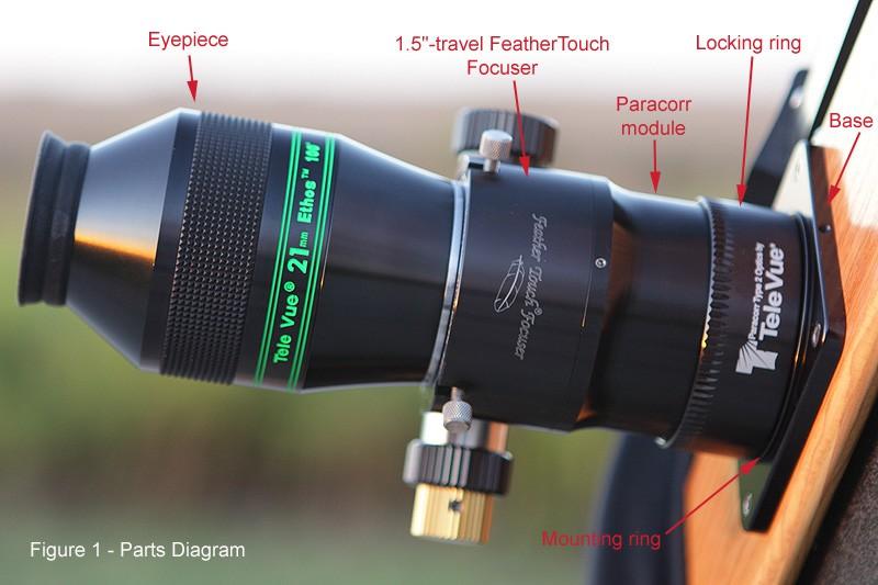
1 SIPS instructions for installation and use Introduction Thank you for purchasing the Starlight Integrated Paracorr System (referred to as SIPS hereafter), which incorporates the best focuser on the market a Starlight FeatherTouch focuser with all the benefits of the Paracorr Type 2. The SIPS is the only combination focuser and stationary coma corrector currently on the market. With this finely crafted piece of equipment set up properly, all you have to do is put in a TeleVue eyepiece. After proper installation, whenever an eyepiece is focused (for infinity-corrected vision), it is automatically at the best position for optimal image quality. No tuning is needed - just enjoy the views. How does it work? Placing the SIPS lenses at the proper location during the adjustment step ensures that you will see the best results that the Paracorr Type 2 system is capable of producing, no matter the focal ratio of your telescope, and no matter which TeleVue eyepiece you place in the focuser. (While the Paracorr and SIPS are tailored for and recommend for use with TeleVue eyepieces, it may be used with oculars manufactured by other companies if the positioning of the focal plane allows them to come to focus.) Considerations for eyeglass wearers The SIPS is meant to be used by people with infinity-corrected vision, which means that observers who are strongly near- or far-sighted should use their glasses and long eyerelief eyepieces when observing with the SIPS. Observing with the SIPS without eyeglasses may induce coma because the eyepiece-to-sips position will vary from its coma-corrected position when the observer focuses. NOTE: If you are strongly near- or far-sighted and prefer to observe without corrected vision (without your glasses), choosing a regular Paracorr 2 with a tunable top instead of a SIPS will maintain coma correction independent of focus position. Coma correction The Paracorr Type 2 is the updated version of the popular Paracorr coma corrector. It offers improved performance over the discontinued Type 1 at all focal ratios, especially in the range below F/4. Using the Paracorr 2 with an F/3 mirror makes it perform like an F/12 without a Paracorr - virtually diffraction limited over the full field as noted on the TeleVue website.
2 Other reasons to choose a SIPS a note by Mike Lockwood Personally, I prefer a SIPS (Starlight Integrated Paracorr System) for four reasons, two optical and two mechanical: 1) I don't binoview. The SIPS usually needs to be completely removed for this. However, binoviewers also don't generally agree well with very fast telescopes anyway, so this is not an issue for me. 2) For infinity-corrected vision, the Paracorr 2 in the SIPS is always perfectly "tuned" after the setup procedure is completed. I never have to worry about tuning it, no matter what eyepiece is used. This saves me time while observing. However, I don't wear glasses. If you do, you will want to keep them on so that you are infinity-corrected. 3) The lens group is always exactly centered on the optical axis and is never tilted. The way it is machined ensures this. The tunable top Paracorr 2 unit can tilt slightly in some focusers as the thumbscrews are tightened, slightly degrading images. I have experienced this myself, and it is clearly noticeable under good observing conditions. 4) The SIPS unit has its mass closer to the focuser board, resulting in slightly less flexure of a focuser board. With the tunable top Paracorr, the Paracorr and an eyepiece are extended well above the focuser, increasing flexure of the system and focuser board. When using the SIPS, the focuser has only the eyepiece in the barrel, and this results in less flexure of the focuser. For these reasons, I recommend the SIPS for all visual Newtonian telescopes, and have used it myself down to f/2.8, and even f/2.55 in an experimental instrument. Designing your telescope for use with the SIPS It is simple to design for the SIPS if you are building your own telescope. Refer to Figure 13 at the end of this document this diagram shows where the focal plane would be if the Paracorr was not there - 88mm above the bottom lens. So, for your telescope design, put the focal plane 88mm from the bottom of where the SIPS lens will be. (This value does not change with f/#.) This will let you size the secondary mirror for a given illuminated field. From the diagram, note that the locking ring (the part that has "STARLIGHT INSTRUMENTS, LLC" painted on it), which contacts the top of the mounting plate and locks the rotation of the SIPS unit after it is adjusted, adjusts from 20-40mm from the bottom lens. Let's center it at 30mm for sake of this example, leaving you 10mm of adjustment up or down to tune the SIPS during the initial setup, which should be enough unless the telescope is set up differently than most. That means that we have: 88 mm - 30 mm = 58 mm from the focal plane to the top of the mounting plate.
3 The mounting plate is 6mm thick, so the focal plane should be: 58 mm + 6 mm = 64 mm from the top of the focuser board. So, that's your rule - set the telescope up to put the focal plane about 64 mm (~2.5") above the top surface of your focuser board, and then install and tune the SIPS as per the SIPS instructions. In case you're wondering how large of a field you should illuminate with the secondary mirror, TeleVue calculated the fully illuminated field for the Paracorr 2, assuming a 60" focal length: f/ mm f/ mm f/ mm f/ mm f/ mm f/ mm So, as you can see, that's large enough for comfortable visual use down to f/2.5, and because our vision is not sensitive to a a smooth falloff in illumination, we probably won't notice that at low powers. I have never actually noticed illumination falloff in my 20 F/3 or my 14.5" F/2.55. Now it's time to install the SIPS. Diagram The parts of the SIPS are labeled in Figure 1. (The eyepiece is not included!) The focuser portion is a standard 1.5"-travel Feather Touch focuser. The focuser can be purchased with the rest of the unit, or you may use your own 1.5"-travel Feather Touch if you already have one. IMPORTANT: The SIPS unit was designed for use with the 1.5"-travel, 2"diameter Feathertouch focuser. Other diameters will not fit. Longer focusers will bottom out, possibly providing insufficient travel. Shorter focusers may also provide insufficient travel. By removing the need to tune the Paracorr, less focuser travel is required to reach focus with all TeleVue eyepieces. The 1.5"-travel model comfortably covers the required focusing range. The focuser portion is mounted on the Paracorr module of the SIPS. It is attached with three setscrews. The Paracorr module sits below it. A locking ring is threaded onto the Paracorr module. Loosening this ring allows the whole assembly to be rotated. This adjusts the height of the whole assembly by threading it into or out of the mounting ring, which sits below the locking ring and inside of the base. The base mounts on your telescope.
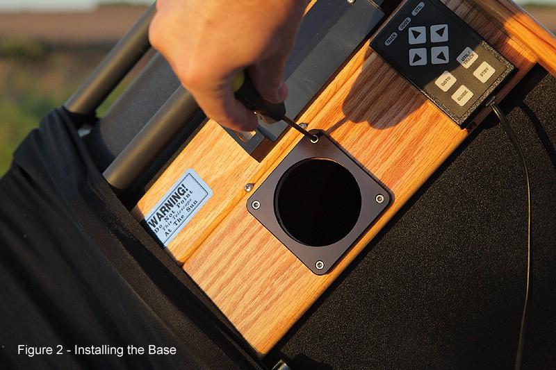
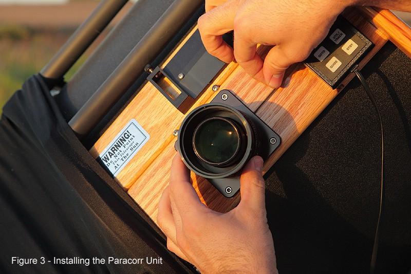
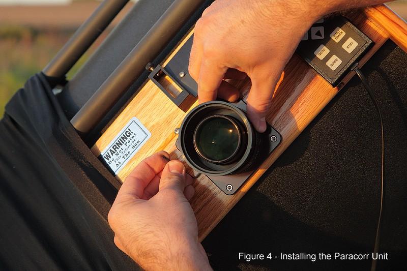
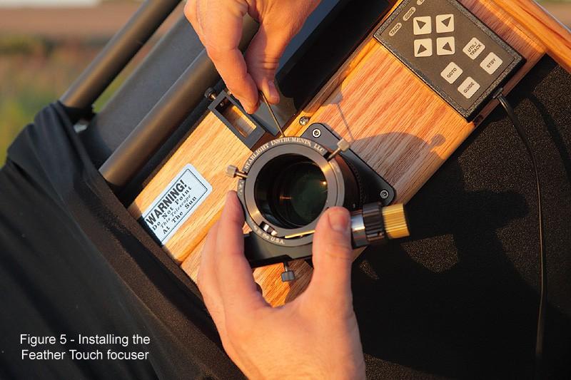
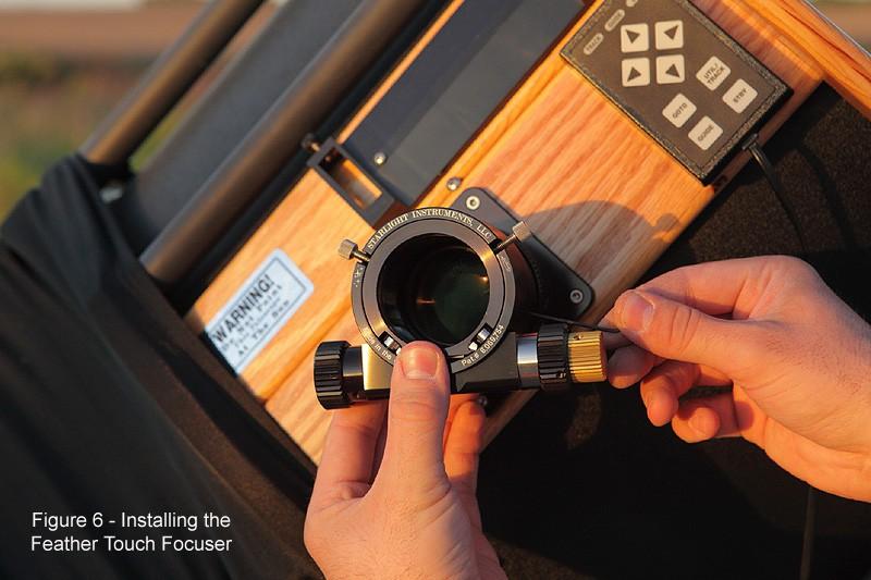
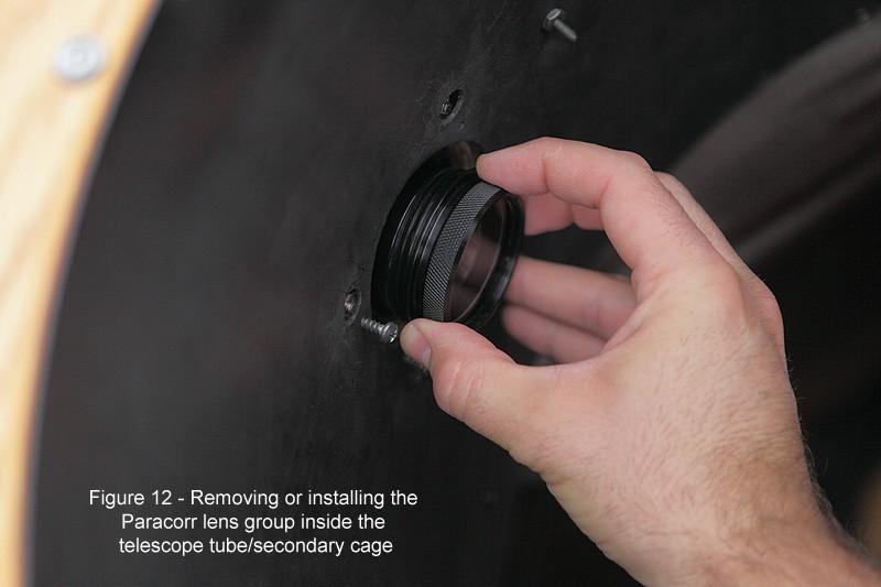
4 Installation Carefully unpack the SIPS unit parts. If you already have a 1.5"-travel Feather Touch focuser mounted on your telescope, detach it from the base by loosening the two setscrews that hold it in place. Either a leveling base or standard base (without leveling screws) may be used with the SIPS. If you do not have a Feather Touch focuser, you will need to purchase and install the focuser and SIPS package. To install the base, accurately center the base over the existing hole and drill mounting holes. Install the base using the provided bolts and nuts (Figure 2). Next, verify that the mounting ring and locking ring are both threaded onto the SIPS Unit. Install this assembly in the base by tightening the two setscrews on opposite sides of the base (Figures 3, 4) using the provided hex wrench. Install the Feather Touch focuser on top of the SIPS Unit by tightening the three setscrews around the top of the unit (Figures 5, 6). But first rack-out the drawtube! This completes the assembly of the SIPS unit. If you have purchased a leveling base, then after the focuser is installed, align the focuser using the adjustment screws. Assemble your telescope if you have not already done so. Collimation To collimate your telescope, you must remove the Paracorr lens group. We recommend pointing your telescope near or at the horizon before removing the lens group. (This will reduce the chance of dropping it onto the ground should you lose your grip on it.) Reach inside the secondary cage and grasp the knurled bottom of the Paracorr lens group. Carefully unscrew it (counterclockwise). You will feel gentle resistance from an O-ring that provides friction - this reduces the chance of the lens group becoming loose or falling out due to vibration during transport. After a few turns, the lens group will disengage from the threads and it can then be pulled out carefully into the secondary cage. (See Figure 12.) Carefully set it aside where it will be safe and clean. Perform your collimation procedure as normal with your laser, autocollimator, or other collimation tool(s). To replace the lens group, carefully insert it back into the bottom of the SIPS and turn it clockwise until it stops. Do not over-tighten it.
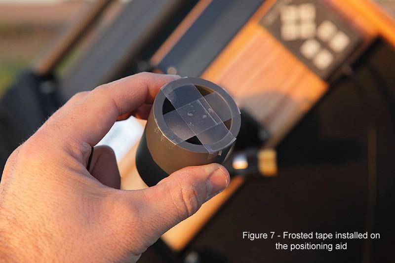
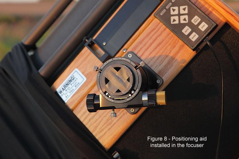
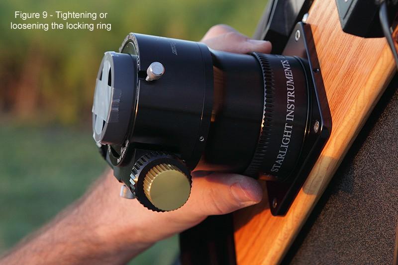
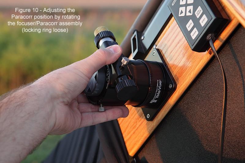
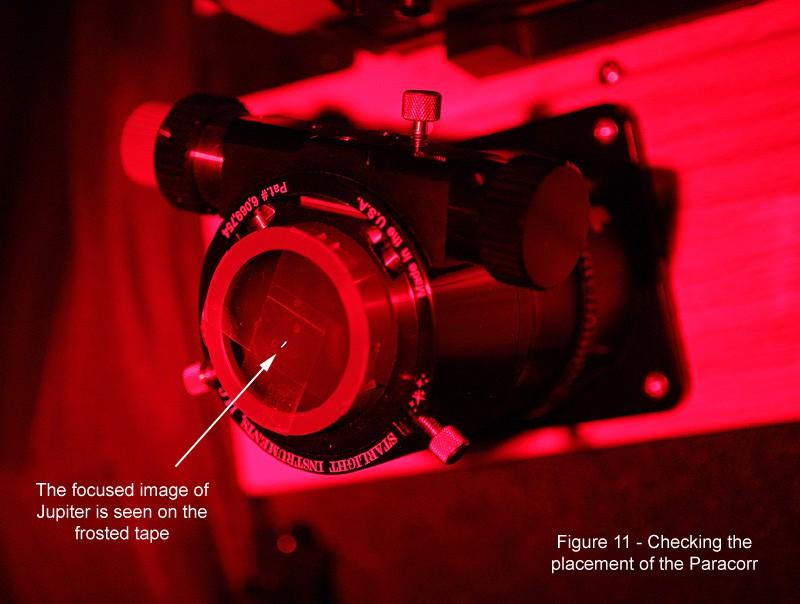
5 Adjustment Now the Paracorr lens group must be positioned the proper distance from your primary mirror. The SIPS may be used before this step is completed, but the best performance will only be obtained after positioning is done. If there is no tape present, place two pieces of frosted tape (Scotch Magic Tape) across the top of the positioning aid (plastic cylinder). This is shown in Figure 7. Under the night sky, point the telescope at the moon, a bright planet, or a bright star. Using an eyepiece, center the object in the field of view. If your telescope has tracking, engage the drive so that the object stays centered in the field of view. If it does not have tracking, you will need to move the telescope every so often to keep it in the field of view. With the object roughly centered, remove the eyepiece, and set it aside where it will be safe. Slide the positioning aid all the way down into the focuser barrel (Figure 8). It will bottom out when it touches the top of the Paracorr lens group. This places the tape at a particular distance from the lenses. Tighten the thumbscrews on the focuser to hold the positioning aid in place. IMPORTANT: Verify that the focuser is racked all the way in, that is, it will go no farther down. The top of the barrel will be even with the top of the focuser housing. Loosen the locking nut by turning it counterclockwise (Figure 9). The entire SIPS assembly may now be turned (Figure 10). Turning it counterclockwise will raise the unit, and turning it clockwise will lower it. Adjust the height of the unit so that the bright object is sharply focused on the tape. This means that you should make the image of a bright star or planet as small as possible on the tape. The moon, however, should be focused as sharply as possible. (Using the edge of the moon's disk may be the easiest way to do this.) Figure 11 shows Jupiter focused on the tape. (Figure 11 was a time exposure and the telescope was not tracking, so it appears as a short, thin line rather than a point.) One method that may make adjustment easier is to thread the SIPS all the way into the base until it stops. Use the focuser to find the sharpest focus, and then raise the unit by rotating it counterclockwise until the sharpest focus occurs when the focuser is racked all the way in (down). With the object focused sharply on the tape and the focuser racked all the way in, adjustment is complete. It is important to realize that this procedure sets the distance between the Paracorr lens group and the primary mirror. If the primary mirror moves up or down in its cell due to collimation adjustments that are made over time, the SIPS position should be adjusted
6 periodically to maintain the proper distance between the Paracorr lens group and the primary mirror. Remove the positioning aid, insert an eyepiece, and enjoy the views! Usage and Accessories The SIPS should always be used when using an eyepiece, or you will likely not be able to reach focus. Take your time and use care when removing or reinstalling the SIPS lenses in the dark. Do not force the lens group back into place if the group does not easily screw into place, stop and inspect the threads and clean if necessary. You may wish to consider removing the SIPS while transporting the telescope. It is possible that very rough roads may cause the lens group to unscrew from the housing. Over time the SIPS lenses and other mechanical parts may become dirty. Please refer to TeleVue's instructions for cleaning the lenses. The mechanical parts, including the threads in the SIPS body and on the lens group, can be cleaned with a soft, damp cloth or cotton swab. Keeping the threads clean will ensure that the threads do not become damaged. Various accessories, such as cameras, binoviewers, etc., may be used so long as they do not come into contact with the Paracorr lens group. Be careful when inserting these accessories into the focuser barrel if you have not previously verified that they do not contact the lenses. (Maximum safe depth below the top of the focuser body is 1-3/4.) To use other accessories that reach more than 1-3/4 into the barrel or require more intravel of the focuser, the SIPS may be removed. Detach the focuser from the SIPS, and remove SIPS from the base without loosening the locking ring or mounting ring (thus ensuring that it will be positioned properly when it is reinstalled. A piece of tape may be used to keep the locking ring from rotating). The focuser may then be mounted directly on the base. To reinstall SIPS, reverse the process described above. Final Notes For information on cleaning of the Paracorr lenses go to the link below, or contact TeleVue directly. Credits: Mike Lockwood ( for his time and effort in the production of this manual.
7
8
9
10
11
12

13 Figure 13 SIPS diagram with dimensions
Hubble Optics CDK 17 Collimation Instructions 03/27/2012 Hubble Optics
 Hubble Optics CDK 17 Collimation Instructions 03/27/2012 Hubble Optics 1: CDK17 Specification: System Effective Focal Length: 2894.7 mm, (this might be slightly different for different set of optics) Figure
PlaneWave CDK Telescope Instructions. Setting the spacing and collimation for the CDK14/17/20/24
 PlaneWave CDK Telescope Instructions Setting the spacing and collimation for the CDK14/17/20/24 Collimation and Secondary Spacing Procedure The CDK optical design has four optical elements shown in Figure
Howie's Laser Collimator Instructions:
 Howie's Laser Collimator Instructions: WARNING: AVOID DIRECT OR MIRROR REFLECTED EYE EXPOSURE TO LASER BEAM The laser collimator is a tool that enables precise adjustment of the alignment of telescope
USING THE 2 TELETUBE XLS TM & TELECAT XLS TM ADJUSTABLE SIGHT TUBE
 USING THE 2 TELETUBE XLS TM & TELECAT XLS TM ADJUSTABLE SIGHT TUBE Revised 09/20/08 With the rapid proliferation of larger-aperture, low f-ratio Newtonian telescopes with 2" focusers and larger diagonal
AG Optical Systems. Newtonian Astrograph Manual Version AG Optical Systems
 AG Optical Systems Newtonian Astrograph Manual Version 2 2012 Table of Contents 1. Introduction 2. System Specifications 3. Initial Assembly 4. Collimation 5. Care and Cleaning 6. Cooling Fan Operation
OWNER S MANUAL. Safety. Please read this owner s manual before use and keep it at hand for reference. Warranty
 Please read this owner s manual before use and keep it at hand for reference. OWNER S MANUAL Safety Important safety instructions for using the INCRA Miter5000 Before using the INCRA Miter5000, read and
The Astronomical League
 The Astronomical League www.astroleague.org Library Telescope Modifications Check the collimation with the eyepiece cap provided (the one with the hole in its center) before starting on any modifications.
Lab 10: Lenses & Telescopes
 Physics 2020, Fall 2010 Lab 8 page 1 of 6 Circle your lab day and time. Your name: Mon Tue Wed Thu Fri TA name: 8-10 10-12 12-2 2-4 4-6 INTRODUCTION Lab 10: Lenses & Telescopes In this experiment, you
SQ2 User Instructions SQ2 Overview:
 SQ2 User Instructions SQ2 Overview: The stationary circular saws including table, radial and chop saws are arguably the most important tools in the shop. They may also be the most difficult to reliably
INSTALLATION INSTRUCTIONS 3 BULL BAR 99-04, 04 "HERITAGE" F-150/250LD 2WD, 97-04, 04 "HERITAGE" 4WD WD EXPEDITION/ WD EXPEDITION PART
 INSTALLATION INSTRUCTIONS 3 BULL BAR PART #B-F1971;B-F2971 PARTS LIST: 1 Bull Bar 2 12-1.75mm x 130mm x 40mm Hex Bolts 1 Driver/Left Mounting Bracket 4 12-1.75mm x 35mm Hex Bolts 1 Passenger/Right Mounting
1503 Follow Spot Yoke, Source Four LED
 1503 Follow Spot Yoke, Source Four LED Rev 1.0 2016 City Theatrical, Inc. Getting Started with the City Theatrical Follow Spot Yoke for source four LED Congratulations on the purchase of your City Theatrical
Step 1 Remove Focus Knob
 Installation Instructions Celestron 14 Edge HD Telescopes Important: The telescope optical tube must be positioned horizontally before removing the original focus assembly. If the telescope is not horizontal
ECEN 4606, UNDERGRADUATE OPTICS LAB
 ECEN 4606, UNDERGRADUATE OPTICS LAB Lab 2: Imaging 1 the Telescope Original Version: Prof. McLeod SUMMARY: In this lab you will become familiar with the use of one or more lenses to create images of distant
Physics 2020 Lab 8 Lenses
 Physics 2020 Lab 8 Lenses Name Section Introduction. In this lab, you will study converging lenses. There are a number of different types of converging lenses, but all of them are thicker in the middle
STEINBERGER TRANSTREM (TYPE 2) TECHNICAL DOCUMENT
 TECHNICAL DOCUMENT") STEINBERGER TRANSTREM (TYPE 2) TECHNICAL DOCUMENT These instructions apply to newer style TransTrems only (non-threaded ball type or modified threaded ball type). For purposes of discussion, these TransTrems
STEINBERGER TRANSTREM (TYPE 2) TECHNICAL DOCUMENT These instructions apply to newer style TransTrems only (non-threaded ball type or modified threaded ball type). For purposes of discussion, these TransTrems
INSTALLATION MANUAL PBL-UMP
 INSTALLATION MANUAL PBL-UMP Table of Contents Warning Statements... 4 Parts List... 5 Installation Tools... 5 Features... 7 Projector Preparation... 8 Bracket Installation... 10 Leveling the Mounting Bracket...
Lumber Smith. Assembly Manual. If you are having problems assembling the saw and need assistance, please contact us at:
 Lumber Smith Assembly Manual If you are having problems assembling the saw and need assistance, please contact us at: 804-577-7398 info@lumbersmith.com 1 Step 1 Safety Carefully read the Owners Manual.
OWNER S MANUAL. But that s just half the story. The fence INCRA Miter Gauge really does work
 From the makers of the INCRA JIG! Please read this owner s manual before use and keep it at hand for reference. Your new INCRA Miter Gauge at long last solves that frustrating problem all too familiar
The only coma-corrector for Newtonian telescopes which does not increase the focal length. An f/4 Newton stays an f/4 Newton! Properties of the MPCC:
 MPCC Mark III Manual Photographic version (for CCD & DSLR): #2458400A V-1 Visual Multi Purpose Coma Corrector Mark III for visual and photographic use #2458403 The only coma-corrector for Newtonian telescopes
Olivier Thizy François Cochard
 Alpy guiding User Guide Olivier Thizy (olivier.thizy@shelyak.com) François Cochard (francois.cochard@shelyak.com) DC0017B : feb. 2014 Alpy guiding module User Guide Olivier Thizy (olivier.thizy@shelyak.com)
(6) Plastic Retainers. Passenger/Right. Passenger/Right Support Brackets
 Plastic Retainers. Passenger/Right. Passenger/Right Support Brackets") PART#R102580 PARTS LIST: 1 Driver/Left HD Running Board 4 8mm Bolt/Nut Plates 1 Passenger/Right HD Running Board 4 8mm Plastic Retainers 2 Driver/Left & Center Mount Bracket 14 8mm-1.25 x 30mm Hex Bolts
PART#R102580 PARTS LIST: 1 Driver/Left HD Running Board 4 8mm Bolt/Nut Plates 1 Passenger/Right HD Running Board 4 8mm Plastic Retainers 2 Driver/Left & Center Mount Bracket 14 8mm-1.25 x 30mm Hex Bolts
7. Michelson Interferometer
 7. Michelson Interferometer In this lab we are going to observe the interference patterns produced by two spherical waves as well as by two plane waves. We will study the operation of a Michelson interferometer,
model tsa-sa48 Sliding Crosscut Table installation guide
 model tsa-sa48 Sliding Crosscut Table installation guide A Note About Color Variations Among Anodized Aluminum Components Congratulations on the purchase of this SawStop Sliding Crosscut Table. We at SawStop
OWNER S MANUAL CONTENTS. The only table saw fence with Automatic Positioning Control TM
 The only table saw fence with Automatic Positioning Control TM OWNER S MANUAL Please read this owner s manual before use and keep it at hand for reference. Note: The INCRA TS II system consists of three
Disc Sander Angle Jig Instructions
 Disc Sander Angle Jig Instructions Congratulations on the purchase of your new Disc Sander Angle Jig! It allows you to sand precise angles on the end of your workpiece and to sand perfectly round circles.
Hubble Optics Ultra Portable UP 12 Dobsonian instruction manual
 Hubble Optics Ultra Portable UP 12 Dobsonian instruction manual Draft: 1.0 12-27-2016 Please read these instructions thoroughly before beginning assembly and subsequent use of the telescope. 1. Unpacking...2
User Manual. Digital Compound Binocular LED Microscope. MicroscopeNet.com
 User Manual Digital Compound Binocular LED Microscope Model MD82ES10 MicroscopeNet.com Table of Contents i. Caution... 1 ii. Care and Maintenance... 2 1. Components Illustration... 3 2. Installation...
Applications of Optics
 Nicholas J. Giordano www.cengage.com/physics/giordano Chapter 26 Applications of Optics Marilyn Akins, PhD Broome Community College Applications of Optics Many devices are based on the principles of optics
AR15 SUPER SLIM AND ULTRA SLIM FREE FLOAT RAIL SYSTEMS
 MUM066011803 AR15 SUPER SLIM AND ULTRA SLIM FREE FLOAT RAIL SYSTEMS Proudly Designed and Made in USA Super Lightweight, Flush Fitting, and Continuous with Flat Top AR15 Upper Receiver Features Integral
INSPECTION AND CORRECTION OF BELLHOUSING TO CRANKSHAFT ALIGNMENT
 INSPECTION AND CORRECTION OF BELLHOUSING TO CRANKSHAFT ALIGNMENT BACKGROUND Proper alignment of the transmission input shaft to the crankshaft centerline is required in order to achieve the best results
EmagiKit. Privacy Pod Plus. Quiet. Easy. Affordable. INSTRUCTIONS ASSEMBLY
 EmagiKit Privacy Pod Plus Quiet. Easy. Affordable. INSTRUCTIONS ASSEMBLY DIMENSIONS AND COMPONENTS 47 47 Ceiling Unit 2-B 2-L 2-R Glass Door Corner Trim Door Handle 90 Adjustable Height Work Surface 1-B
Installing the Partridge RA Extension on Losmandy G11
 Installing the Partridge RA Extension on Losmandy G11 Michael Herman July 20, 2015 Tools: 3/16 inch hex key (allen wrench) [If desired for DEC indicator ring friction improvement: flat screwdriver, and
O5: Lenses and the refractor telescope
 O5. 1 O5: Lenses and the refractor telescope Introduction In this experiment, you will study converging lenses and the lens equation. You will make several measurements of the focal length of lenses and
Hubble Optics Ultra Light UL 16 Dobsonian instruction manual
 Hubble Optics Ultra Light UL 6 Dobsonian instruction manual REV:.. 03-0-202 Please read these instructions thoroughly before beginning assembly and subsequent use of the telescope..unpacking... 2 2. Assembly...
Constable Oak Extension Dining Table
 Constable Oak Extension Dining Table Assembly Instructions - Please keep for future reference 176/0325 Dimensions Width - 160/ 200cm Depth - 90cm Height - 75cm Important - Please read these instructions
VARIABLE SPEED WOOD LATHE
 MODEL MC1100B VARIABLE SPEED WOOD LATHE INSTRUCTION MANUAL Please read and fully understand the instructions in this manual before operation. Keep this manual safe for future reference. Version: 2015.02.02
Eric B. Burgh University of Wisconsin. 1. Scope
 Southern African Large Telescope Prime Focus Imaging Spectrograph Optical Integration and Testing Plan Document Number: SALT-3160BP0001 Revision 5.0 2007 July 3 Eric B. Burgh University of Wisconsin 1.
Inventory (Figure 2)
") MODEL T10130/T10126 6" & 8" SPIRAL CUTTERHEAD INSTRUCTIONS The Model T10126/T10130 indexable insert spiral cutterheads are designed to replace straightknife cutterheads from the Grizzly jointer Models
MODEL T10130/T10126 6" & 8" SPIRAL CUTTERHEAD INSTRUCTIONS The Model T10126/T10130 indexable insert spiral cutterheads are designed to replace straightknife cutterheads from the Grizzly jointer Models
Zoom Stereo Microscope NYMCS-360 Instruction Manual
 Zoom Stereo Microscope NYMCS-60 Instruction Manual This manual is written for stereo microscope NYMCS-60. To ensure the safety, obtain optimum performance and to familiarize yourself fully with the use
Installing CNC Stepper Motor Mounts On A Sherline Lathe
 Installing CNC Stepper Motor Mounts On A Sherline Lathe P/N 6720 (6725 Metric) 4000/4100/4500/4600 Lathes P/N 6730 (6735 Metric) 4400/4410 Lathe USING THE TEMPLATE BLOCKS TO LOCATE NEW MOUNTING HOLES FOR
SPECIFICATIONS. The WM-6XL Long Wm. Malcolm Telescopic Riflescope Instruction Manual WARNING:
 The WM-6XL Long Wm. Malcolm Telescopic Riflescope Instruction Manual SPECIFICATIONS Power: 6X Objective: 17mm Length: 30 in. Weight: 1.85 lb. (29.60 oz.) Eye relief: approx. 4.5 in. Reticle: Fine Crosshair
The following article is a translation of parts of the original publication of Karl-Ludwig Bath in the german astronomical magazine:
 The following article is a translation of parts of the original publication of Karl-Ludwig Bath in the german astronomical magazine: Sterne und Weltraum 1973/6, p.177-180. The publication of this translation
INSTALLATION MANUAL PBC-UMS
 INSTALLATION MANUAL. PBC-UMS Premier Mounts 3130 E. Miraloma Avenue Anaheim, CA 92806 Phone: (800) 368-9700 Fax: (800) 832-4888 mounts@mounts.com www.mounts.com Rev. 01 PBL-110 Projector Mount Page 2 Installation
RPMSP Series Installation Guide
 RPMSP Series Installation Guide Contents 1. Overview... page 1 2. Unpacking the Projector...2 3. Projector Configuration...2 4. Projector Throw Distance and Mounting...9 5. Projection Lens Focus...9 6.
AG Optical Systems LLC
 AG Optical Systems LLC Convergent, Imaging Harmer Wynne, Imaging Dall Kirkham Astrograph Manual Version 1 2019 Please read through the entire manual before making any adjustments to your AG Optical Systems
A socket contact support (supplied separately) must be installed onto the locator assembly.
 must be installed onto the locator assembly.") Figure 1 PRO CRIMPER III Hand Tool Assembly 1976444 1 consists of PRO CRIMPER III Hand Tool Frame 354940 1 and Die Assembly 1976444 2. The tool assembly is used to crimp the contacts listed in Figure 1.
Figure 1 PRO CRIMPER III Hand Tool Assembly 1976444 1 consists of PRO CRIMPER III Hand Tool Frame 354940 1 and Die Assembly 1976444 2. The tool assembly is used to crimp the contacts listed in Figure 1.
OPTICS LENSES AND TELESCOPES
 ASTR 1030 Astronomy Lab 97 Optics - Lenses & Telescopes OPTICS LENSES AND TELESCOPES SYNOPSIS: In this lab you will explore the fundamental properties of a lens and investigate refracting and reflecting
Adjusting Backlash on Sherline handwheels
 WEAR YOUR SAFETY GLASSES FORESIGHT IS BETTER THAN NO SIGHT READ INSTRUCTIONS BEFORE OPERATING Adjusting Backlash on Sherline handwheels What Is Backlash? Backlash is the amount the handwheel can turn before
Congratulations! You are now on your way to enriching your life with!
 C) Using the base point as your reference, measure up 8-1/32 and mark a horizontal line. Measure in from the edge of the door the distance of your backset and mark where the two lines cross. This will
Want to make a travel scope but too lazy to read the whole thing? Read this:
 My 114mm Travel Scope by Cyrille de Brebisson of Rhône-Alpes, France cyrille.de.brebisson@gmail.com During my last trip in the US, I was able to pick a 114mm/25.4mm primary/secondary mirror pair for 18$
Instruction Manual T Binocular Acromat Research Scope T Trinocular Acromat Research Scope
 Research Scope Instruction Manual T-29031 Binocular Acromat Research Scope T-29041 Trinocular Acromat Research Scope T-29032 Binocular Semi-Plan Research Scope T-29042 Trinocular Semi-Plan Research Scope
FAIRFAX ROUGHING-IN K-12151T=673. UNIT: mm K-12153T K-12156T K-12151T=610 K-12157T K-12161T T01-A -1- INSTALLATION INSTRUCTIONS
 FAIRFAX INSTALLATION INSTRUCTIONS BATHROOM ACCESSORIES K-12151T/K-12153T/K-12156T/ K-12157T/K-12158T/K-12161T/K-12162T BEFORE YOU BEGIN Congratulation on your purchase of this high quality Bathroom Accessory.
Physics 208 Spring 2008 Lab 2: Lenses and the eye
 Name Section Physics 208 Spring 2008 Lab 2: Lenses and the eye Your TA will use this sheet to score your lab. It is to be turned in at the end of lab. You must use complete sentences and clearly explain
1. Turn off or disconnect power to unit (machine). 2. Push IN the release bar on the quick change base plate. Locking latch will pivot downward.
. 2. Push IN the release bar on the quick change base plate. Locking latch will pivot downward.") Figure 1 Miniature Quick Change Applicators, of the end feed type, are designed to crimp end feed strip terminals to prestripped wires. Each applicator is set up to accept the strip form of certain specific
Figure 1 Miniature Quick Change Applicators, of the end feed type, are designed to crimp end feed strip terminals to prestripped wires. Each applicator is set up to accept the strip form of certain specific
Corner Key Doweling Jig Instructions Effective July 2018
 Corner Key Doweling Jig Instructions Effective July 2018 Review full manual instructions prior to use for important safety information. Always check Rockler.com to confirm that you are using the most recent
Maintenance Information
 16601023 Edition 2 January 2014 Air Impact Wrench 2705P1 Maintenance Information Save These Instructions Product Safety Information WARNING Failure to observe the following warnings, and to avoid these
Customer Notice: Congratulations again on your SawStop purchase, and thank you! -SawStop Tualatin, OR
 Customer Notice: Congratulations on the purchase of this Sliding Crosscut Attachment. As the owner of a SawStop saw, you are familiar with our high standards for quality, fit and finish. Different from
Q-Zone Hoop-Frame. Assembly Instructions. Copyright July 11, 2018 Grace Company (Reproduction Prohibited) Version 1.8
 Version 1.8") Q-Zone Hoop-Frame Assembly Instructions Copyright July 11, 2018 Grace Company (Reproduction Prohibited) Version 1.8 Table of Contents Table of Contents... i Warranty... ii Parts List Box 1...iii Box 2...
Q-Zone Hoop-Frame Assembly Instructions Copyright July 11, 2018 Grace Company (Reproduction Prohibited) Version 1.8 Table of Contents Table of Contents... i Warranty... ii Parts List Box 1...iii Box 2...
Removing outter components
 Y Axis Motor Replacement Replacing the Y axis motor is a process that requires the individual to be somewhat mechanically inclined and can follow detailed instructions. If any of the following steps are
Thermostatic Valve Trim
 Thermostatic Valve Trim P23052-CR, P23052-LV, P23122-LV, P23222-RK, P23222-LV, P24022-CL, P24022-CR, P24022-KL, P24022-RB, P24022-RL, P24122-CR, P24122-LV, P24129-CR, P24129-LV, P24421-CR, P24421-LV, P24422-CR,
MODEL T27697 & T " & 8" HELICAL CUTTERHEADS INSTALLATION INSTRUCTIONS
 MODEL T27697 & T27699 6" & 8" HELICAL CUTTERHEADS INSTALLATION INSTRUCTIONS For questions or help with this product contact Tech Support at (570) 546-9663 or techsupport@grizzly.com These indexable insert
MODEL T10815 GRINDING ATTACHMENTS INSTRUCTIONS
 MODEL T10815 GRINDING ATTACHMENTS INSTRUCTIONS For questions or help with this product contact Tech Support at (570) 546-9663 or techsupport@grizzly.com Introduction Designed to work exclusively with the
Ribcage Installation. Part 2 - Assembly. Back-Bone V1.06
 Ribcage Installation Part 2 - Assembly Back-Bone V1.06 Contents Section 1 Before You Get Started... 2 Included With Your Kit:... 2 Figure: A... 3 CAUTION!... 4 Note:... 4 Tools Required... 5 Section 2:
PLANISHING HAMMER STAND OWNER S MANUAL
 PLANISHING HAMMER STAND OWNER S MANUAL WARNING: Read carefully and understand all INSTRUCTIONS before operating. Failure to follow the safety rules and other basic safety precautions may result in serious
GlideRite Retractable Cover System For HotSpring & Tiger River Spas (except Classic & pre-2000 Landmark Spas)
") List of Contents Quantity Description 12 #10 x 1 ½ Flat Head Phillips Screw (see pg. 2) 2 #10 x ½ Pan Head Phillips Screw (see pg. 2) 8 ¼ x 2 ½ Lag Bolt (see pg. 2) 7 ¼ 20 x 5 / 8 Hex Head Bolt (see pg.
List of Contents Quantity Description 12 #10 x 1 ½ Flat Head Phillips Screw (see pg. 2) 2 #10 x ½ Pan Head Phillips Screw (see pg. 2) 8 ¼ x 2 ½ Lag Bolt (see pg. 2) 7 ¼ 20 x 5 / 8 Hex Head Bolt (see pg.
PRODUCT: LOKI INSTALLATION INSTRUCTIONS. Product is covered by U.S. patents. For more information visit
 R INSTALLATION INSTRUCTIONS PRODUCT: LOKI CONFIGURATION: SINGLE DOOR MOUNT: GLASS MOUNT Product is covered by U.S. patents. For more information visit www.krownlab.com . TOOLS + MATERIALS REQUIRED TOOLS
Mighty Mo GX Series Cabinet Installation Guide. OR Rev /11
 Mighty Mo GX Series Cabinet Installation Guide OR-71601787 Safety and Warning ATTENTION The exclamation point within an equilateral triangle is intended to alert the user to the presence of important operating
INSTALLATION MANUAL ELPMBUNI
 INSTALLATION MANUAL ELPMBUNI Warning Statements WARNING: WARNING: WARNING: WARNING: PREMIER MOUNTS DOES NOT WARRANT AGAINST DAMAGE CAUSED BY THE USE OF ANY PREMIER MOUNTS PRODUCT FOR PURPOSES OTHER THAN
Adaptive Coronagraphy Using a Digital Micromirror Array
 Adaptive Coronagraphy Using a Digital Micromirror Array Oregon State University Department of Physics by Brad Hermens Advisor: Dr. William Hetherington June 6, 2014 Abstract Coronagraphs have been used
Ceiling Tile Installations Part 1. Sheetrock Installations Part 2. WolfVision Support 2055 Sugarloaf Circle, Suite 125 Duluth, GA 30097
 Ceiling Tile Installations Part 1 Sheetrock Installations Part 2 WolfVision Support 2055 Sugarloaf Circle, Suite 125 Duluth, GA 30097 (877) 873-WOLF support@wolfvision.us 0 EYE Series Mounting Kit Part
VARIABLE SPEED WOOD LATHE. Model DB900 INSTRUCTION MANUAL
 VARIABLE SPEED WOOD LATHE Model DB900 INSTRUCTION MANUAL 1007 TABLE OF CONTENTS SECTION...PAGE Technical data.. 1 General safety rules....1-3 Specific safety rules for wood lathe.....3 Electrical information.4
For Barrel Tapers. Installation and Operating Instructions For use with small combination belt & disk sanders. Assembled Taper Tool
 Tim s Taper Tool For Barrel Tapers Installation and Operating Instructions For use with small combination belt & disk sanders Assembled Taper Tool Your taper tool is capable of making barrel tapered shafts.
FACTORY CAT TOMCAT CORPORATION
 FACTORY CAT RPS TOMCAT CORPORATION Artificial Turf and Carpet Sweeping Install Kit #349-641 & #349-642 1. Detach batteries so that there is no power running through the machine before starting. 2. Start
TITAN-BIT KEY-CUTTING MACHINE INSTRUCTION MANUAL
 TITAN-BIT KEY-CUTTING MACHINE INSTRUCTION MANUAL Contents: 1 PRESENTATION AND GENERAL ASPECTS... 3 1.1 GENERAL POINTS... 3 1.2 TRANSPORT AND PACKING... 3 1.3 IDENTIFICATION LABEL... 3 2 CHARACTERISTICS
MODEL T " SPIRAL CUTTERHEAD INSTALLATION INSTRUCTIONS
 MODEL T27449 8" SPIRAL CUTTERHEAD INSTALLATION INSTRUCTIONS The Model T27449 indexable insert spiral cutterhead is designed to replace the straightknife cutterhead on the Grizzly jointer Model G0490W/G0490XW
Motorized M3 AX7200 Rotary-Style Gasket Cutter Operating Instructions
 Motorized M3 AX7200 Rotary-Style Gasket Cutter Operating Instructions INTRODUCTION Congratulations! You are the owner of the finest rotary-style gasket cutter in the world. Originally developed and patented
ML7520 ML7530 DIOPTER ADJUSTMENT RING BINOCULAR BODY, INCLINED 30. (a) Field Iris Control Lever. (c) Filter Slots EYEPIECES, KHW10X
 Field Iris Control Lever. (c) Filter Slots EYEPIECES, KHW10X") JAPAN DIOPTER ADJUSTMENT RING BINOCULAR BODY, INCLINED 30 (a) Field Iris Control Lever (c) Filter Slots EYEPIECES, KHW10X ANALYZER CONTROL LEVER (b) Aperture Iris Control Lever LIGHT SOURCE HOUSING VERTICAL
JAPAN DIOPTER ADJUSTMENT RING BINOCULAR BODY, INCLINED 30 (a) Field Iris Control Lever (c) Filter Slots EYEPIECES, KHW10X ANALYZER CONTROL LEVER (b) Aperture Iris Control Lever LIGHT SOURCE HOUSING VERTICAL
Sliding Crosscut Table installation guide
 Sliding Crosscut Table installation guide model tsa-sa48 A Note About Color Variations Among Anodized Aluminum Components Congratulations on the purchase of this SawStop Sliding Crosscut Table. We at SawStop
JK Rear Crusher Flares
 INSTALLATION INSTRUCTIONS INST-17-05-010_A JK Rear Crusher Flares IMPORTANT: Thank you for purchasing this Poison Spyder product. Please read through this entire document before proceeding with installation.
PHYS 3153 Methods of Experimental Physics II O2. Applications of Interferometry
 Purpose PHYS 3153 Methods of Experimental Physics II O2. Applications of Interferometry In this experiment, you will study the principles and applications of interferometry. Equipment and components PASCO
Replacing the build plate clamps
 Repair manual Replacing the build plate clamps Instructions The build plate clamps hold the glass plate in place on the heated bed. There are two fixed in place at the back of the heated bed and two at
MM340 Installation Instructions IMPORTANT SAFETY INSTRUCTIONS - SAVE THESE INSTRUCTIONS
 MM30 Installation Instructions IMPORTANT SAFETY INSTRUCTIONS - SAVE THESE INSTRUCTIONS Please read this entire manual before you begin. Do not unpack any contents until you verify all requirements on PAGE.
Reading: Lenses and Mirrors; Applications Key concepts: Focal points and lengths; real images; virtual images; magnification; angular magnification.
 Reading: Lenses and Mirrors; Applications Key concepts: Focal points and lengths; real images; virtual images; magnification; angular magnification. 1.! Questions about objects and images. Can a virtual
WILLIS WALL-MOUNT FAUCET INSTALLATION
 SKU(s): 924620 BEFORE YOU BEGIN We recommend consulting a professional if you are unfamiliar with installing bathroom fixtures and plumbing. Signature Hardware accepts no liability for any damage to the
Exercise 8: Interference and diffraction
 Physics 223 Name: Exercise 8: Interference and diffraction 1. In a two-slit Young s interference experiment, the aperture (the mask with the two slits) to screen distance is 2.0 m, and a red light of wavelength
Installing CNC Stepper Motor Mounts On A Sherline Mill
 Installing CNC Stepper Motor Mounts On A Sherline Mill P/N 6700 (6710 Metric) 5000/5100/5400/5410 Mills P/N 6705 (6715 Metric) 2000/2010 Mills USING THE TEMPLATE BLOCKS TO LOCATE NEW MOUNTING HOLES FOR
INSTALLATION INSTRUCTIONS 3"/4 BENT END SIDEBARS FORD F-150 SUPERCREW PART # DZ /DZ
 INSTALLATION INSTRUCTIONS 09-12 FORD F-150 SUPERCREW PART # DZ 372697/DZ 372699 PARTS LIST: 1 Driver/Left Sidebar 4 1/2 Lock Washers 1 Sidebar 4 12mm x 32mm OD x 3mm Flat Washers 1 Driver/Left Mounting
Geometric Optics. Objective: To study the basics of geometric optics and to observe the function of some simple and compound optical devices.
 Geometric Optics Objective: To study the basics of geometric optics and to observe the function of some simple and compound optical devices. Apparatus: Pasco optical bench, mounted lenses (f= +100mm, +200mm,
ULTRAFEED INDUSTRIAL TABLE PACKAGES Set-up Guide for #120931, # & #121091
 120932*1 Instructions for Sailrite Ultrafeed Industrial Table Packages ULTRFEE INUSTRIL TBLE PKGES Set-up Guide for #120931, #120934 & #121091 2 Ultrafeed Industrial Table Packages The Ultrafeed Industrial
PACIFIC LASER SYSTEMS. HVL100 Procedures
 PACIFIC LASER SYSTEMS HVL100 Procedures A. Setting Up for Level Calibration of Horizontal Lines, Plumb and Down pg. 2 B. Setting Up for Vertical Line Calibration pg. 4 C. Setting Up for Square Calibration
Gared Pro-S Portable Backstop
 Models: 9616 & 9618 Installation, Operation and Maintenance Instructions Please read all instructions before attempting installation or operation of these units SAVE THESE INSTRUCTIONS FOR FUTURE USE PUBLICATION
LIGHT BEAM ANTENNA MaxRange Antenna Series Assembly Instructions MaxRange Plus Digital / High Definition Television Antennas
 LIGHT BEAM ANTENNA MaxRange Antenna Series Assembly Instructions MaxRange Plus Digital / High Definition Television Antennas Assembly Instructions 1 MaxRange Plus Antenna These instructions will lead you
Installation Instructions FW8S-STXL / FW8G-STXL Filter Wheel
 Installation Instructions FW8S-STXL / FW8G-STXL Filter Wheel SBIG Astronomical Instruments, A Division of Diffraction Limited. 59 Grenfell Crescent, Unit B, Ottawa, ON Canada, k2g 0G3 Tel: 613.225.2732
TP3100(EA) Series TP3123(EA) / TP3126(EA) / TP3129(EA) / TP3132(EA)
 Series TP3123(EA) / TP3126(EA) / TP3129(EA) / TP3132(EA)") PEDAL TIMPANI TP3100(EA) Series TP3123(EA) / TP3126(EA) / TP3129(EA) / TP3132(EA) Owner s Manual Thank you for purchasing a Yamaha Timpani. Please read through this manual carefully as it contains important
PEDAL TIMPANI TP3100(EA) Series TP3123(EA) / TP3126(EA) / TP3129(EA) / TP3132(EA) Owner s Manual Thank you for purchasing a Yamaha Timpani. Please read through this manual carefully as it contains important
GlideRite Retractable Cover System For Hot Spot Spas (SE & SLX only)
") List of Contents Quantity Description 12 #10 x 1 ½ Flat Head Phillips Screw (see pg. 2) 2 #10 x ½ Pan Head Phillips Screw (see pg. 2) 8 ¼ x 2 ½ Lag Bolt (see pg. 2) 7 ¼ 20 x 5 / 8 Hex Head Bolt (see pg.
List of Contents Quantity Description 12 #10 x 1 ½ Flat Head Phillips Screw (see pg. 2) 2 #10 x ½ Pan Head Phillips Screw (see pg. 2) 8 ¼ x 2 ½ Lag Bolt (see pg. 2) 7 ¼ 20 x 5 / 8 Hex Head Bolt (see pg.
Band-Master ATS Nano Pneumatic Banding Tool Operating Instructions
 Band-Master ATS 601-118 Nano Pneumatic Banding Tool CONTENTS 601-118 Overview... 3 Safety.... 5 Initial Tool Set-up... 5 Regulator assembly mounting... 5 Attach tool head to regulator.... 6 Operating instructions...
Due to possible damage in shipping, the vertical stop assembly has been removed from this machine.
 Due to possible damage in shipping, the vertical stop assembly has been removed from this machine. To assemble, insert the threaded rod through the shroud opening in the top of the machine. Start the four
User Manual. Trinocular Infinity Compound LED Microscope. MicroscopeNet.com
 User Manual Trinocular Infinity Compound LED Microscope Model M8333Z series MicroscopeNet.com Table of Contents i. Caution... 1 ii. Care and Maintenance... 2 1. Components Illustration... 3 2. Installation...
MODEL T28173/T28174 ROLLER TABLES INSTRUCTIONS
 MODEL T28173/T28174 ROLLER TABLES INSTRUCTIONS FOR MODELS MFD. SINCE 10/17 For questions or help with this product contact Tech Support at (570) 546-9663 or techsupport@grizzly.com Rails Rollers Reversible
Operation Manual Panel Mounting Gas Pressure Regulators
 687 Technology Way Napa, CA 94558 Phone: (707) 259-0102 FAX: (707) 259-0117 www.aptech-online.com Table of Contents: A. General information... 1 B. Panel Mount Nut - AP/AZ/AK/SL Model Regulators... 1 C.