Acceptance test for the linear motion actuator for the scanning slit of the HIE ISOLDE short diagnostic boxes
|
|
|
- Silvester Daniels
- 6 years ago
- Views:
Transcription

1 EUROPEAN ORGANIZATION FOR NUCLEAR RESEARCH CERN ACC NOTE HIE ISOLDE PROJECT Note 0036 Acceptance test for the linear motion actuator for the scanning slit of the HIE ISOLDE short diagnostic boxes E.D. Cantero, W. Andreazza, E. Bravin, A. Sosa Abstract We performed experimental tests to characterize the mechanical accuracy of a linear actuator designed by the company AVS for the movement of the scanning slit of the HIE ISOLDE short diagnostic boxes. The mechanism consists of a linear actuator composed of two guiding rods and a lead screw, with a full stroke of 135 mm. A specially designed blade was mounted on the actuator and the transverse positioning of the blade was monitored with a camera based optical system while moving the actuator at speeds of up to 10 mm/s. The repeatability of the positioning of the blade after several cycles around predefined positions was also measured. The results of the measurements and a general inspection of the device show that the proposed solution fulfils the specifications. A full prototype of short diagnostic box for the HIE ISOLDE project can now be built for testing. Geneva, Switzerland October 2014 This is an internal CERN publication and does not necessarily reflect the views of the CERN management.
2 Contents 1. Introduction Experimental setup Procedure Results and discussion Visual inspection Amplitude of oscillations for full stroke movements Movement back and forth around each hole (6 mm, 15 cycles) Limit switches precision Evaluation of counts losses Movement back and forth from hole 1 to hole 6 (100 mm steps, 15 cycles) Movement back and forth around hole 3 (3 mm steps, 50 cycles) Preliminary stress test of the mechanism (full stroke, 100 cycles) Overall results overview Conclusions Acknowledgements References
3

4 Vibrations of the slit in the transverse direction during a scan can in fact reduce the precision of the beam profile measurement. This document describes the tests performed between 3 and 6 February 2014 at the headquarters of Added Value Solutions in Elgoibar, Spain. It follows the main guidelines of the test procedure described in Ref. [4]. 2. Experimental setup The prototype HIE DB was installed in an experimental hall (grey room) of AVS. The body of prototype HIE diagnostic box was used as vacuum tank for the experiment. The new linear actuator under test was installed on the scanning slit port of the tank by means of an ad hoc adapting piece. A dedicated metallic blade was mounted at the end of the rod of the actuator (vacuum side) and was scanned across (what would be) the beam axis during the tests (there was clearly no particle beam involved in this test). Two optical viewports were mounted on the beam pipe flanges. A light source (Edmund MI 150 high intensity illuminator) and a CCD camera (IDS UI 2210SE) were also installed facing the mentioned viewports on either side of the tank, their supports being independent and mechanically detached from the DB support. A thin (2 mm thick) teflon (PTFE) plate was placed in front of the lamp to diffuse the light in order to have a homogeneous illumination of the viewport. The actuator for the faraday cup was also installed in the DB, as well as a high vacuum pumping group with a turbo molecular pump. A picture of the experimental setup is presented in Fig. 2. Figure 2 Experimental setup. 4

5 In Fig. 3 detailed pictures of the linear actuator and its limit switches are shown. The mechanism has two guiding rods and the linear motion is driven by a ball bearing screw connected to a stepper motor. The screw pitch is 1 mm and the full stroke of the mechanism is about 135 mm. The forward limit switch (bellow fully compressed) is used only as a safety interlock to prevent damage to the mechanical parts. The rear limit switch (bellow extended) is used as safety interlock as well as reference for the homing position. The control unit for the stepper motor, including the limit switches, was provided by AVS together with a custom designed software utility. The external temperature of the stepper motor was monitored by a thermocouple connected to a digital multimeter, during the tests the temperature of the motor never exceeded 40 ºC. Figure 3 Linear translation mechanism of the scanning slit. In Fig. 4 a picture of the scanning blade used in these tests is depicted, together with a drawing showing the main geometrical parameters. The blade has two slits (0.2 mm 5
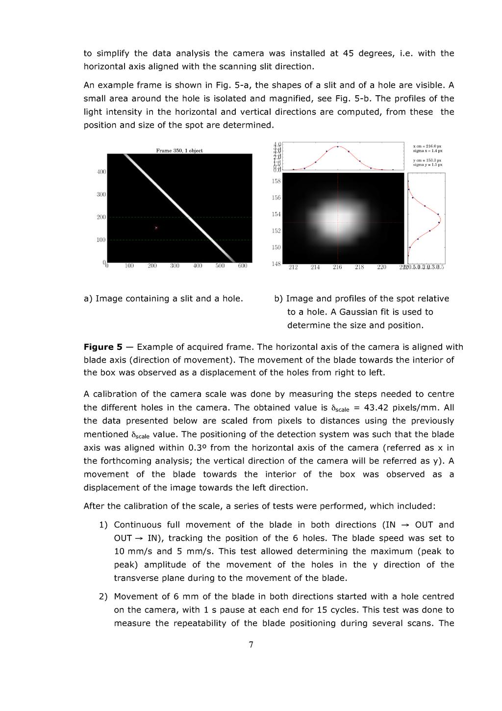
 were also drilled in the blade axis and were used for monitoring the blade transverse position during the measurements.")
6 width) at 45 degrees from the axis of movement (these slits are similar to the ones that will be used for the beam profiles measurements). Six holes (0.1 mm diameter) were also drilled in the blade axis and were used for monitoring the blade transverse position during the measurements. For more details about the scanning blade geometry, please refer to [4]. Figure 4 Blade with two slits and six drilled holes used for determining the accuracy on the positioning of the linear actuator. Holes are labelled as hole 1 to hole 6 from the innermost to the outermost position. 3. Procedure The experimental procedure consisted of tracking the positions of the drilled holes for different blade transverse positions, either with the blade at a fixed location or while it was moved at speeds of up to 10 mm/s. When the scanning blade crossed the beam aperture the light passing through the drilled holes (or the slits) was detected by the camera. By analysing the size and position of the light spots frame by frame, the displacements of the blade due to mechanical vibrations were determined. The exposure time of the camera was set to texposure = 100 s with a frame rate of 37.6 FPS. The size of the frames was 640 x 480 pixels with 8 bits grey levels. The experience was carried out with high vacuum conditions (P ~ mbar). In order 6
7
8 blade speed was set to 10 mm/s. For holes 1 and 6, the test was also performed at 5 mm/s. 3) Movement of the full stroke of the blade touching both limit switches, without updating the home position, for 10 consecutive cycles. This test was done to measure the accuracy in the position of the blade by using the limit switches as reference. Blade speed was 10 mm/s. 4) Starting with the blade fully OUT, move in steps of ~7 mm until the forward limit switch was reached, then back to the position full OUT in one move. This sequence was repeated 10 times in order to verify that the motor was not losing steps along the movement. 5) Movement of the blade in both directions, starting with hole 1 centred on the camera (i.e. in the beam axis) and until hole 6 was centred (total movement length 100 mm), for 15 cycles. This is a repetition of point (2) but with a longer stroke. 6) Starting with hole 3 centred on the camera, move 3 mm back and forth for 50 cycles to test repeatability of the positioning for a large number of cycles. 7) Preliminary stress test of the mechanism: movement of the full stroke of the actuator for 100 cycles, with 1 s pause between movements. The temperature of the stepper motor was monitored during the test to evaluate the correct dimensioning of it. A general inspection of the device was done in order to check for signs of wear or any issues related with the design and implementation of the proposed solution. The results of the previously enumerated measurements and other examinations of the device are presented in the following section. 4. Results and discussion 4.1. Visual inspection The design of the system with two guiding rods and the moving force applied directly on the centre of the actuator looks reliable. The use of a ball screw to reduce the friction in the conversion from rotational to linear motion is a good solution, increasing the smoothness of the blade movement. The screw pitch of 1 mm is adequate and, together with the stepper motor, provides sufficient resolution in the positioning of the blade. Limit switches are placed correctly and allow a full stroke of ~135 mm which covers the complete scan of both slits (vertical and horizontal profiles). The device is compatible with ultra high vacuum standards. For the production devices the lubrication of the screw should be done with grease approved by CERN considering that the boxes will be used in a radiation environment Amplitude of oscillations for full stroke movements The blade was moved at 10 mm/s over the full stroke (OUT IN) and the position of the 6 holes, while passing in the field of view of the camera (~14 mm wide), were 8
9
10
11
12
13
14
15
16
17
18
19
20 had a standard deviation of 3 counts for each limit switch. The translation of this value to distances in the linear movement gives the result RMS limit switch repeatability ~2 m Evaluation of counts losses The blade was moved IN in several steps of 7 mm with pauses of 1 s until the forward limit switch was reached, and then moved fully OUT in one large step. This test was used to evaluate the possibility of lost counts/steps during the acceleration and deceleration processes, and was repeated 10 times. The standard deviation on the number of counts during the 10 cycles was of a few counts (out of a total of for the full stroke), which indicates that the loss of counts was inexistent or completely negligible Movement back and forth from hole 1 to hole 6 (100 mm steps, 15 cycles) Starting with a position where hole 1 was centred in the camera frame, the blade was moved back and forth 100 mm for 15 cycles. The blade positioning in the direction of the movement changed less than 5 m between the first and last cycle Movement back and forth around hole 3 (3 mm steps, 50 cycles) The test described in section 4.3 was repeated using hole 3, a blade speed of 10 mm/s and a shorter stroke (3 mm), for 50 continuous cycles. The repeatability of the hole position after these cycles was of the order of 2 m Preliminary stress test of the mechanism (full stroke, 100 cycles) The blade was moved back and forth between both limit switches for 100 cycles, with a pause of 1 s before reversing the direction of motion. The temperature of the stepper motor was monitored and did not rise above 30ºC Overall results overview The proposed mechanical design for the scanning slit actuator for the HIE ISOLDE short boxes is a solid solution that has been thoroughly tested using a HIE DB prototype. The repeatability on the positioning of the blade after several scans and changes in the direction of the movements should be better than 100 m, according to specifications [1], in order not to worsen the resolution for the beam profiles measurement. The repeatability in the positioning of the blade measured indirectly by tracking a series of holes drilled on it is better than 20 m, a value that fulfils the requirements. The chosen stepper motor can provide the needed torque and move the slit at the reference speed of 10 mm/s without problems. The system is quoted to be UHV compatible, although a proper vacuum test should be done following CERN standard procedures before final acceptance of the prototype. A preliminary stress test was performed (100 continuous cycles, full stroke) and no issues were observed. The procedure and materials used for lubrication should be considered carefully as the device is to be used in a radiation environment. 20
21 5. Conclusions The tests consisted of performing several scans of the blade movement in both directions (IN OUT and OUT IN), at speeds of up to 10 mm/s and determining the transverse position of the blade by using an optical system. All the results show that the accuracy in terms of the blade transverse positioning meet the acceptance criteria defined in the functional specification for the HIE ISOLDE beam diagnostic systems [1]. The test procedure of Ref. [4] was fully completed and the results were satisfactory, as a consequence the status of this acceptance test is: APPROVED. 6. Acknowledgements The authors would like to thank the technical support provided by José Miguel Carmona, Julio Galipienzo and Juan Reyes during their time in AVS. 7. References [1] HIE B FS 0001, M. Fraser et al, "Beam Diagnostic Boxes for HIE ISOLDE" CERN EDMS [2] Added Value Solutions. Pol. Ind. Sigma Xixilion, Kalea 2, Bajo Pabellón Elgoibar, Gipuzkoa. Spain. v s.es/ [3] HIE BDB TN 0001, E. Bravin et al, "Failure on the scanning slit movement of the prototype HIE ISOLDEDiagnostic Box", EDMS [4] HIE BDB PRD 0001, E. D. Cantero et al, Mechanical positioning test procedure for the scanning blade of the HIE ISOLDE diagnostic boxes, EDMS
LUSI Pulse Picker System
 ENGINEERING SPECIFICATION DOCUMENT (ESD) Doc. No. SP-391-001-50 R0 LUSI SUB-SYSTEM DCO LUSI Pulse Picker System Rick Jackson Design Engineer, Author Signature Date Marc Campell DCO Design Engineer Signature
Radial Polarization Converter With LC Driver USER MANUAL
 ARCoptix Radial Polarization Converter With LC Driver USER MANUAL Arcoptix S.A Ch. Trois-portes 18 2000 Neuchâtel Switzerland Mail: info@arcoptix.com Tel: ++41 32 731 04 66 Principle of the radial polarization
Supplementary Figure 1
 Supplementary Figure 1 Technical overview drawing of the Roadrunner goniometer. The goniometer consists of three main components: an inline sample-viewing microscope, a high-precision scanning unit for
Introduction... 3 Slits for AIR Operation... 4 Slits in Vacuum Vessels... 5 Slits for High Vacuum Operation... 6 Custom Slits... 7 Steel Slits...
 Introduction... 3 Slits for AIR Operation... 4 Slits in Vacuum Vessels... 5 Slits for High Vacuum Operation... 6 Custom Slits... 7 Steel Slits... 10 Non-magnetic Options for Slits... 12 Slits with Passive
CMS Note Mailing address: CMS CERN, CH-1211 GENEVA 23, Switzerland
 Available on CMS information server CMS NOTE 1998/16 The Compact Muon Solenoid Experiment CMS Note Mailing address: CMS CERN, CH-1211 GENEVA 23, Switzerland January 1998 Performance test of the first prototype
Supplementary Figure S1. Schematic representation of different functionalities that could be
 Supplementary Figure S1. Schematic representation of different functionalities that could be obtained using the fiber-bundle approach This schematic representation shows some example of the possible functions
Problem/Procedure Description. Requirements. Problem/Procedure Solution. How-To Document. Updated on: 11/13/2008 By:Christopher Ware
 Problem/Procedure Description Performing maintenance on 95s, 95sII and H100 Requirements Ball Bearing Grease (LPKF P/N 106976) Tri-Flow Teflon lubricant aerosol. 3-in-1 Multi-purpose Oil Electronic Component
A novel solution for various monitoring applications at CERN
 A novel solution for various monitoring applications at CERN F. Lackner, P. H. Osanna 1, W. Riegler, H. Kopetz CERN, European Organisation for Nuclear Research, CH-1211 Geneva-23, Switzerland 1 Department
OPTICS IN MOTION. Introduction: Competing Technologies: 1 of 6 3/18/2012 6:27 PM.
 1 of 6 3/18/2012 6:27 PM OPTICS IN MOTION STANDARD AND CUSTOM FAST STEERING MIRRORS Home Products Contact Tutorial Navigate Our Site 1) Laser Beam Stabilization to design and build a custom 3.5 x 5 inch,
001-Component-build. Build the following Contraptor components before assembly:
 001-Component-build Build the following Contraptor components before assembly: http://www.contraptor.org/make-linear-rail-v2#assembly http://www.contraptor.org/make-linear-bearings-v2#assembly http://www.contraptor.org/make-sliding-elements#assembly
PICO MASTER 200. UV direct laser writer for maskless lithography
 PICO MASTER 200 UV direct laser writer for maskless lithography 4PICO B.V. Jan Tinbergenstraat 4b 5491 DC Sint-Oedenrode The Netherlands Tel: +31 413 490708 WWW.4PICO.NL 1. Introduction The PicoMaster
Physics Requirements for the CXI 0.1 micron Sample Chamber
 PHYSICS REQUIREMENT DOCUMENT (PRD) Doc. No. SP-391-000-20 R1 LUSI SUB-SYSTEM Coherent X-Ray Imaging Physics Requirements for the Sébastien Boutet CXI Scientist, Author Signature Date Paul Montanez CXI
Roman Pots. Marco Oriunno SLAC, PPA. M.Oriunno, SLAC
 Roman Pots Marco Oriunno SLAC, PPA The Roman Pot technique 1. The Roman Pot, an historically successful technique for near beam physics: ISR, SPS, TEVATRON, RICH, DESY 2. A CERN in-house technology: ISR,
Assembly procedure for KA_S series January, 04, 2010
 Assembly procedure for KA_S series January, 04, 2010 The following procedure is valid for KA060S and KA080S. However, only pictures of KA060S are shown as examples. The other is similar. 1. Examine specification
Supplementary Information
 Supplementary Information Supplementary Figure 1. Modal simulation and frequency response of a high- frequency (75- khz) MEMS. a, Modal frequency of the device was simulated using Coventorware and shows
Seal Mechanism of Tip Seal in Scroll Compressor
 Purdue University Purdue e-pubs International Compressor Engineering Conference School of Mechanical Engineering 214 Seal Mechanism of Tip Seal in Scroll Compressor Mitsuhiro Fukuta Shizuoka University,
Compact and Reliable Speckle Reduction
 Compact and Reliable Speckle Reduction August 2017 Mark Ventura, Vice President Sales & Marketing Optotune Switzerland AG Bernstrasse 388 CH-8953 Dietikon Switzerland Phone +41 58 856 3011 www.optotune.com
A Study of undulator magnets characterization using the Vibrating Wire technique
 A Study of undulator magnets characterization using the Vibrating Wire technique Alexander. Temnykh a, Yurii Levashov b and Zachary Wolf b a Cornell University, Laboratory for Elem-Particle Physics, Ithaca,
Introduction of New Products
 Field Emission Electron Microscope JEM-3100F For evaluation of materials in the fields of nanoscience and nanomaterials science, TEM is required to provide resolution and analytical capabilities that can
On spatial resolution
 On spatial resolution Introduction How is spatial resolution defined? There are two main approaches in defining local spatial resolution. One method follows distinction criteria of pointlike objects (i.e.
Upgrade of the ultra-small-angle scattering (USAXS) beamline BW4
 beamline BW4") Upgrade of the ultra-small-angle scattering (USAXS) beamline BW4 S.V. Roth, R. Döhrmann, M. Dommach, I. Kröger, T. Schubert, R. Gehrke Definition of the upgrade The wiggler beamline BW4 is dedicated to
Upgrade of the ultra-small-angle scattering (USAXS) beamline BW4 S.V. Roth, R. Döhrmann, M. Dommach, I. Kröger, T. Schubert, R. Gehrke Definition of the upgrade The wiggler beamline BW4 is dedicated to
LEAD SCREW LINEAR ACTUATORS Profile Rail Linear Actuators
 LEAD SCREW LINEAR ACTUATORS Profile Rail Linear Actuators ITAR Helix Linear Technologies, Inc., Beachwood, Ohio COMPANY CULTURE Helix is a global supplier to the Medical Device, Life Science, Security,
Mechanical study of the «Saclay piezo tuner» PTS (Piezo Tuning System) P. Bosland, Bo Wu DAPNIA - CEA Saclay. Abstract
 P. Bosland, Bo Wu DAPNIA - CEA Saclay. Abstract") SRF Mechanical study of the «Saclay piezo tuner» PTS (Piezo Tuning System) P. Bosland, Bo Wu DAPNIA - CEA Saclay Abstract This report presents the piezo tuner developed at Saclay in the framework of CARE/SRF.
SRF Mechanical study of the «Saclay piezo tuner» PTS (Piezo Tuning System) P. Bosland, Bo Wu DAPNIA - CEA Saclay Abstract This report presents the piezo tuner developed at Saclay in the framework of CARE/SRF.
HBS-AP ASSEMBLING INSTRUCTIONS
 ALUMINIUM PIPEWORK - ALUMINIUM PIPEWORK - ALUMINIUM PIPEWORK 97 HBS-AP ASSEMBLING INSTRUCTIONS 1. INTRODUCTION 1.1. This manual is very easy to consult and we recommend reading it before starting work,
SPECTRAL SCANNER. Recycling
 SPECTRAL SCANNER The Spectral Scanner, produced on an original project of DV s.r.l., is an instrument to acquire with extreme simplicity the spectral distribution of the different wavelengths (spectral
A Breakthrough in Sputtering Target Inspections: Ultra-High Speed Phased Array Scanning with Volume Focusing
 17th World Conference on Nondestructive Testing, 25-28 Oct 2008, Shanghai, China A Breakthrough in Sputtering Target Inspections: Ultra-High Speed Phased Array Scanning with Volume Focusing Dominique Braconnier,
Assembly and Experimental Characterization of Fiber Collimators for Low Loss Coupling
 Assembly and Experimental Characterization of Fiber Collimators for Low Loss Coupling Ruby Raheem Dept. of Physics, Heriot Watt University, Edinburgh, Scotland EH14 4AS, UK ABSTRACT The repeatability of
Easy-To-Use Graphic Interface
 Graphical Robot Programming Teachbox for Robot W 711 The Wittmann CNC 6.2 robot control with color graphics screens allows simpler robot teaching and use than ever before. The operator simply traces out
INSTRUCTION MANUAL Q-HYDRAULIC
 Dat: 15.04.02 No: 94-BA 5039E/1b TABLE OF CONTENTS Part III 3.0 Type code explanation 3.1 Service connections 3.2 Impeller clearance adjustment 3.2.1 Wear of wearing parts 3.2.2 General notes to adjustment
Laser Speckle Reducer LSR-3000 Series
 Datasheet: LSR-3000 Series Update: 06.08.2012 Copyright 2012 Optotune Laser Speckle Reducer LSR-3000 Series Speckle noise from a laser-based system is reduced by dynamically diffusing the laser beam. A
PERFORMANCE OF THE TUNER MECHANISM FOR SSR1 RESONATORS DURING FULLY INTEGRETED TESTS AT FERMILAB
 PERFORMANCE OF THE TUNER MECHANISM FOR SSR1 RESONATORS DURING FULLY INTEGRETED TESTS AT FERMILAB D. Passarelli, J.P. Holzbauer, L. Ristori, FNAL, Batavia, IL 651, USA Abstract In the framework of the Proton
SIPS instructions for installation and use
 SIPS instructions for installation and use Introduction Thank you for purchasing the Starlight Integrated Paracorr System (referred to as SIPS hereafter), which incorporates the best focuser on the market
Check the LCLS Project website to verify 2 of 7 that this is the correct version prior to use.
 1. Introduction: The XTOD Offset System (OMS) is designed to direct the LCLS FEL beam to the instruments and experimental stations, while substantially reducing the flux of unwanted radiation which accompanies
Experiment 1: Fraunhofer Diffraction of Light by a Single Slit
 Experiment 1: Fraunhofer Diffraction of Light by a Single Slit Purpose 1. To understand the theory of Fraunhofer diffraction of light at a single slit and at a circular aperture; 2. To learn how to measure
Screw Driven automation tables
 automation tables Precise multi-axis positioning systems play an integral part in today s semiconductor, computer peripheral, solar power, flat panel, life sciences, lab automation, biomedical and electronics
1 Operating Manual Wedge Angle Scanner
 1 Operating Manual Wedge Angle Scanner Operating Manual Wedge Angle- Scanner (Wedge Angle Scanner Flatscan HUD) OEG GmbH Wildbahn 8i 15236 Frankfurt (Oder) Tel.: 0335 5213894 Fax: 0335 5213896 E-mail:
APPLICATIONS FOR TELECENTRIC LIGHTING
 APPLICATIONS FOR TELECENTRIC LIGHTING Telecentric lenses used in combination with telecentric lighting provide the most accurate results for measurement of object shapes and geometries. They make attributes
LOS 1 LASER OPTICS SET
 LOS 1 LASER OPTICS SET Contents 1 Introduction 3 2 Light interference 5 2.1 Light interference on a thin glass plate 6 2.2 Michelson s interferometer 7 3 Light diffraction 13 3.1 Light diffraction on a
Interposer MATED HEIGHT
 Product Specification: FEATURES High Performance PCBeam Connector Technology Product options at 1.27mm, 1.0mm, and 0.8mm pitch Maximized pin count per form factor 3 form factor sizes available Standard
PicoMaster 100. Unprecedented finesse in creating 3D micro structures. UV direct laser writer for maskless lithography
 UV direct laser writer for maskless lithography Unprecedented finesse in creating 3D micro structures Highest resolution in the market utilizing a 405 nm diode laser Structures as small as 300 nm 375 nm
Updates and Programme for SLAC RC Tests
 Updates and Programme for SLAC RC Tests LHC Collimation Upgrade Specification Meeting April 11 th, 2014 G. Valentino, P. Gradassi with input from: O. Berrig, A. Bertarelli, N. Biancacci, F. Carra, M. Donze,
Parallel Beam Linear Sensor
 Parallel Beam Linear Sensor Visible Red Class II Laser Width/Profile Measurement Sensor Providing High-Speed Precision Measurement with Flexible Operation H FDA Class II IEC Class 2 visible red laser ensures
Standard Operating Procedure
 Standard Operating Procedure Nanosurf Atomic Force Microscopy Operation Facility NCCRD Nanotechnology Center for Collaborative Research and Development Department of Chemistry and Engineering Physics The
Preliminary Version. Working with the Blade of the Opus1 Gouger Robin Driscoll October 2003
 Preliminary Version Working with the Blade of the Opus1 Gouger Robin Driscoll October 2003 One of the most interesting aspects of the Opus1 Gouger is the multitude of adjustments that are now easily in
Micro-manipulated Cryogenic & Vacuum Probe Systems
 Janis micro-manipulated probe stations are designed for non-destructive electrical testing using DC, RF, and fiber-optic probes. They are useful in a variety of fields including semiconductors, MEMS, superconductivity,
CXI 1 micron Precision Instrument Stand
 Engineering specification Document (ESD) Doc. No. SP-391-001-44 R0 LUSI SUB-SYSTEM CXI Instrument Prepared by: Jean-Charles Castagna Design Engineer Signature Date Co-authored by: Paul Montanez CXI Lead
Status of the Electron Beam Transverse Diagnostics with Optical Diffraction Radiation at FLASH
 Status of the Electron Beam Transverse Diagnostics with Optical Diffraction Radiation at FLASH M. Castellano, E. Chiadroni, A. Cianchi, K. Honkavaara, G. Kube DESY FLASH Seminar Hamburg, 05/09/2006 Work
Eric B. Burgh University of Wisconsin. 1. Scope
 Southern African Large Telescope Prime Focus Imaging Spectrograph Optical Integration and Testing Plan Document Number: SALT-3160BP0001 Revision 5.0 2007 July 3 Eric B. Burgh University of Wisconsin 1.
Factors Affecting Pre-Tension and Load Carrying Capacity in Rockbolts - A Review of Fastener Design
 University of Wollongong Research Online Coal Operators' Conference Faculty of Engineering and Information Sciences 2018 Factors Affecting Pre-Tension and Load Carrying Capacity in Rockbolts - A Review
Product Specification - LPM Connector Family
 LPM Product Specification - LPM OVERVIEW Developed for mobile devices and other space-constrained applications, the Neoconix LPM line of connectors feature exceptional X-Y-Z density with a simple, highly
Dynamic Stability Characteristics of HSP-CM at Mach 4
 Dynamic Stability Characteristics of HSP-CM at Mach 4 Presentation at MATLAB EXPO India, 2017 20.04.2017 By, Aaron Baptista, Sci/Engr Akhtedar Abbas Khan, Sci/Engr MD Jamal Nawaz Ansari, SCI/Engr R Saravanan,
plasmonic nanoblock pair
 Nanostructured potential of optical trapping using a plasmonic nanoblock pair Yoshito Tanaka, Shogo Kaneda and Keiji Sasaki* Research Institute for Electronic Science, Hokkaido University, Sapporo 1-2,
DISCO DICING SAW SOP. April 2014 INTRODUCTION
 DISCO DICING SAW SOP April 2014 INTRODUCTION The DISCO Dicing saw is an essential piece of equipment that allows cleanroom users to divide up their processed wafers into individual chips. The dicing saw
New Long Stroke Vibration Shaker Design using Linear Motor Technology
 New Long Stroke Vibration Shaker Design using Linear Motor Technology The Modal Shop, Inc. A PCB Group Company Patrick Timmons Calibration Systems Engineer Mark Schiefer Senior Scientist Long Stroke Shaker
CHAPTER 5 FAULT DIAGNOSIS OF ROTATING SHAFT WITH SHAFT MISALIGNMENT
 66 CHAPTER 5 FAULT DIAGNOSIS OF ROTATING SHAFT WITH SHAFT MISALIGNMENT 5.1 INTRODUCTION The problem of misalignment encountered in rotating machinery is of great concern to designers and maintenance engineers.
Design and Development of Novel Two Axis Servo Control Mechanism
 Design and Development of Novel Two Axis Servo Control Mechanism Shailaja Kurode, Chinmay Dharmadhikari, Mrinmay Atre, Aniruddha Katti, Shubham Shambharkar Abstract This paper presents design and development
QuantumScan-7 & 10 Moving Magnet Galvanometers
 QuantumScan-7 & 10 Moving Magnet Galvanometers QuantumScan-10 For 10-15 mm Beam Apertures Patent Pending Ceramic Rotor For Faster Step Response Patent Pending Rear Adjustable Stops 3X Greater Position
System Options. Magnetic Property Measurement System. AC Susceptibility. AC Susceptibility Specifications
 System Options AC Susceptibility Magnetic Property Measurement System Many materials display dissipative mechanisms when exposed to an oscillating magnetic field, and their susceptibility is described
Manual Rotation Stages
 ~1mm Table mm Table Side-Mount, Aluminum Body, Slide Guide 88 mm Table Side-Mount, Aluminum Body, Slide Guide 88 mm Table Side-Mount, Aluminum Body, Cross-Roller or Slide Guide 9 mm Table Side-Mount, Aluminum
The Henryk Niewodniczański INSTITUTE OF NUCLEAR PHYSICS Polish Academy of Sciences ul. Radzikowskiego 152, Kraków, Poland.
 The Henryk Niewodniczański INSTITUTE OF NUCLEAR PHYSICS Polish Academy of Sciences ul. Radzikowskiego 152, 31-342 Kraków, Poland. www.ifj.edu.pl/reports/2003.html Kraków, grudzień 2003 Report No 1931/PH
Design and Fabrication of Automatic Wood Drilling Machine
 Design and Fabrication of Automatic Wood Drilling Machine Deepak Devasagayam #1 Anthony Ignatious #2, Jason Kalathingal *3, Joy Kakde #4, *5 Mechanical Engineering Department, Fr. C.R.I.T., Vashi. Navi
DETERMINING CALIBRATION PARAMETERS FOR A HARTMANN- SHACK WAVEFRONT SENSOR
 DETERMINING CALIBRATION PARAMETERS FOR A HARTMANN- SHACK WAVEFRONT SENSOR Felipe Tayer Amaral¹, Luciana P. Salles 2 and Davies William de Lima Monteiro 3,2 Graduate Program in Electrical Engineering -
Workshop IGLEX Andromède & ThomX 23 June 2016, LAL Orsay. The X-line of ThomX.
 Workshop IGLEX Andromède & ThomX 23 June 2016, LAL Orsay The X-line of ThomX jerome.lacipiere@neel.cnrs.fr mjacquet@lal.in2p3.fr Brightness panorama of X-ray (10-100 kev) sources Synchrotron : not very
Parallel Mode Confocal System for Wafer Bump Inspection
 Parallel Mode Confocal System for Wafer Bump Inspection ECEN5616 Class Project 1 Gao Wenliang wen-liang_gao@agilent.com 1. Introduction In this paper, A parallel-mode High-speed Line-scanning confocal
4) Drive Mechanisms. Techno_Isel H830 Catalog
 Drive Mechanisms. Techno_Isel H830 Catalog") 4) Drive Mechanisms This section will introduce most of the more common types of drive mechanisms found in linear motion machinery. Ideally, a drive system should not support any loads, with all the loads
4) Drive Mechanisms This section will introduce most of the more common types of drive mechanisms found in linear motion machinery. Ideally, a drive system should not support any loads, with all the loads
Our service team is at your disposal for further information. Franke GmbH Obere Bahnstr Aalen Germany Tel.: /920-0 Fax.
 Our service team is at your disposal for further information. Franke GmbH Obere Bahnstr. 64 73431 Aalen Germany Tel.: 07361 /9200 Fax.: 07361/920120 www.frankegmbh.com www.frankebearings.de www.frankelinearguides.de
Photographing Long Scenes with Multiviewpoint
 Photographing Long Scenes with Multiviewpoint Panoramas A. Agarwala, M. Agrawala, M. Cohen, D. Salesin, R. Szeliski Presenter: Stacy Hsueh Discussant: VasilyVolkov Motivation Want an image that shows an
System Options. Magnetic Property Measurement System. AC Susceptibility. AC Susceptibility Specifications
 System Options AC Susceptibility Magnetic Property Measurement System Many materials display dissipative mechanisms when exposed to an oscillating magnetic field, and their susceptibility is described
TITAN-BIT KEY-CUTTING MACHINE INSTRUCTION MANUAL
 TITAN-BIT KEY-CUTTING MACHINE INSTRUCTION MANUAL Contents: 1 PRESENTATION AND GENERAL ASPECTS... 3 1.1 GENERAL POINTS... 3 1.2 TRANSPORT AND PACKING... 3 1.3 IDENTIFICATION LABEL... 3 2 CHARACTERISTICS
ARCoptix. Radial Polarization Converter. Arcoptix S.A Ch. Trois-portes Neuchâtel Switzerland Mail: Tel:
 ARCoptix Radial Polarization Converter Arcoptix S.A Ch. Trois-portes 18 2000 Neuchâtel Switzerland Mail: info@arcoptix.com Tel: ++41 32 731 04 66 Radially and azimuthally polarized beams generated by Liquid
Module-4 Lecture-2 Perpendicularity measurement. (Refer Slide Time: 00:13)
") Metrology Prof. Dr. Kanakuppi Sadashivappa Department of Industrial and Production Engineering Bapuji Institute of Engineering and Technology-Davangere Module-4 Lecture-2 Perpendicularity measurement (Refer
Metrology Prof. Dr. Kanakuppi Sadashivappa Department of Industrial and Production Engineering Bapuji Institute of Engineering and Technology-Davangere Module-4 Lecture-2 Perpendicularity measurement (Refer
Thorough Small Angle X-ray Scattering analysis of the instability of liquid micro-jets in air
 Supplementary Information Thorough Small Angle X-ray Scattering analysis of the instability of liquid micro-jets in air Benedetta Marmiroli a *, Fernando Cacho-Nerin a, Barbara Sartori a, Javier Pérez
PRODUCTS & SERVICES GUIDE
 PRODUCTS & SERVICES GUIDE IT S YOUR MOVE. 2 ROCKFORD BALL SCREW ABOUT US Ian McBain founded Rockford Ball Screw (RBS) in 1973 utilizing his years of experience in the industry with the goals of providing
Lecture 18. Chapter 24 Milling, Sawing, and Filing; Gear Manufacturing (cont.) Planing
 Planing") Lecture 18 Chapter 24 Milling, Sawing, and Filing; Gear Manufacturing (cont.) Planing For production of: Flat surfaces Grooves Notches Performed on long (on average 10 m) workpieces Workpiece moves / Tool
Lecture 18 Chapter 24 Milling, Sawing, and Filing; Gear Manufacturing (cont.) Planing For production of: Flat surfaces Grooves Notches Performed on long (on average 10 m) workpieces Workpiece moves / Tool
NOISE REDUCTION IN SCREW COMPRESSORS BY THE CONTROL OF ROTOR TRANSMISSION ERROR
 C145, Page 1 NOISE REDUCTION IN SCREW COMPRESSORS BY THE CONTROL OF ROTOR TRANSMISSION ERROR Dr. CHRISTOPHER S. HOLMES HOLROYD, Research & Development Department Rochdale, Lancashire, United Kingdom Email:
Vipros 357 Queen User Pre-installation Guide
 Vipros 357 Queen User Pre-installation Guide Amada America Inc. 7025 Firestone Blvd. Buena Park CA. 90621 Phone: (714) 739 2111 Fax.: (714) 739 4099 Email info@amada.com Print Date 03/04/99 Revision 2.0
PH 481/581 Physical Optics Winter 2014
 PH 481/581 Physical Optics Winter 2014 Laboratory #1 Week of January 13 Read: Handout (Introduction & Projects #2 & 3 from Newport Project in Optics Workbook), pp.150-170 of Optics by Hecht Do: 1. Experiment
Product Specification - LPS Connector Series
 LPS Product Specification - LPS OVERVIEW The LPS products are solderable versions of those in the Neoconix LPM product series. Also developed for mobile devices and other space-constrained applications,
Optimization of the LCLS Single Pulse Shutter
 SLAC-TN-10-002 Optimization of the LCLS Single Pulse Shutter Solomon Adera Office of Science, Science Undergraduate Laboratory Internship (SULI) Program Georgia Institute of Technology, Atlanta Stanford
ULTRASONIC IMAGING of COPPER MATERIAL USING HARMONIC COMPONENTS
 ULTRASONIC IMAGING of COPPER MATERIAL USING HARMONIC COMPONENTS T. Stepinski P. Wu Uppsala University Signals and Systems P.O. Box 528, SE- 75 2 Uppsala Sweden ULTRASONIC IMAGING of COPPER MATERIAL USING
Q1. The figure below shows two ways in which a wave can travel along a slinky spring.
 PhysicsAndMathsTutor.com 1 Q1. The figure below shows two ways in which a wave can travel along a slinky spring. (a) State and explain which wave is longitudinal..... On the figure above, (i) clearly indicate
of the rollers on top of each other for each press of the rollers. A self-supporting rack enables the avoidance of misalignment
 Products for levelling and shaping band saws, guide rails, circular saws and circular knives MR 0 The MR 0 is conducive to the levelling of saw bands and guide rails. With the addition of an auxiliary
Vipros 357 User Pre-installation Guide
 Amada America Inc. Vipros 357 User Pre-installation Guide Amada America Inc. 7025 Firestone Blvd. Buena Park CA. 90621 Phone: (714) 739 2111 Fax.: (714) 739 4099 Email infoamada.com Print Date 04/02/99
SUMMARY. V-Lock SYSTEM BASIC ELEMENTS ACTUATORS. P V-Lock GENERAL INTRODUCTION 2. P V-Lock FIXING ELEMENTS 10 SUMMARY. P V-Lock ADAPTORS 17
 SUMMARY A3 V-Lock SYSTEM P V-Lock GENERAL INTRODUCTION 2 BASIC ELEMENTS P V-Lock FIXING ELEMENTS 10 P V-Lock ADAPTORS 17 SUMMARY P PROFILES 28 P V-Lock ACCESSORIES AND SPARE PARTS 32 1 A3 GENERAL INTRODUCTION
Physics B Waves and Sound Name: AP Review. Show your work:
 Physics B Waves and Sound Name: AP Review Mechanical Wave A disturbance that propagates through a medium with little or no net displacement of the particles of the medium. Parts of a Wave Crest: high point
HIGH RESOLUTION COMPUTERIZED TOMOGRAPHY SYSTEM USING AN IMAGING PLATE
 HIGH RESOLUTION COMPUTERIZED TOMOGRAPHY SYSTEM USING AN IMAGING PLATE Takeyuki Hashimoto 1), Morio Onoe 2), Hiroshi Nakamura 3), Tamon Inouye 4), Hiromichi Jumonji 5), Iwao Takahashi 6); 1)Yokohama Soei
Experiment 10. Diffraction and interference of light
 Experiment 10. Diffraction and interference of light 1. Purpose Perform single slit and Young s double slit experiment by using Laser and computer interface in order to understand diffraction and interference
Size 23 Single Stack Size 23 Double Stack. 30-in (760 mm) 225 lbs (1,000 N) lbs-ft (30.5 Nm) lbs-ft (26.25 Nm) lbs-ft (30.
 225 lbs (1,000 N) lbs-ft (30.5 Nm) lbs-ft (26.25 Nm) lbs-ft (30.") HAYD: 203 756 7441 BGS Motorized Linear Rails: BGS08 Recirculating Ball Slide BGS08 Linear Rail with Hybrid 57000 Series Size 23 Single and Double Stacks This BGS heavy-duty linear rail combines many technologies
HAYD: 203 756 7441 BGS Motorized Linear Rails: BGS08 Recirculating Ball Slide BGS08 Linear Rail with Hybrid 57000 Series Size 23 Single and Double Stacks This BGS heavy-duty linear rail combines many technologies
Vibrating Wire R&D for Alignment of Multipole Magnets in NSLS-II
 Vibrating Wire R&D for Alignment of Multipole Magnets in NSLS-II 10 th International Workshop on Accelerator Alignment February 11-15, 2008, Tsukuba, Japan Animesh Jain for the NSLS-II magnet team Collaborators
High-Resolution Corrosion Monitoring for Reliable Assessment of Infrastructure
 19 th World Conference on Non-Destructive Testing 2016 High-Resolution Corrosion Monitoring for Reliable Assessment of Infrastructure André Lamarre 1 1 Olympus Scientific Solutions Americas, Quebec City,
CSNC CARBIDE CIRCULAR SERIES
 CSNC CARBIDE CIRCULAR SERIES HIGHLY EFFICIENT AND PRODUCTIVE HIGH SPEED CIRCULAR SAWING MACHINES CARBIDE SAWS DO THE WORK OF FIVE CONVENTIONAL FACTORY BAND SAWS, WITHOUT SACRIFICING QUALITY. GET THE CLOSE-CUT
Optical basics for machine vision systems. Lars Fermum Chief instructor STEMMER IMAGING GmbH
 Optical basics for machine vision systems Lars Fermum Chief instructor STEMMER IMAGING GmbH www.stemmer-imaging.de AN INTERNATIONAL CONCEPT STEMMER IMAGING customers in UK Germany France Switzerland Sweden
Set Up and Test Results for a Vibrating Wire System for Quadrupole Fiducialization
 LCLS-TN-06-14 Set Up and Test Results for a Vibrating Wire System for Quadrupole Fiducialization Michael Y. Levashov, Zachary Wolf August 25, 2006 Abstract A vibrating wire system was constructed to fiducialize
Testo SuperResolution the patent-pending technology for high-resolution thermal images
 Professional article background article Testo SuperResolution the patent-pending technology for high-resolution thermal images Abstract In many industrial or trade applications, it is necessary to reliably
Ensat driving tools...
 nsat driving tools... On this page, you can configure the optimum tool for your application. A configuration is provided in the following as an illustrative example. The article number is composed of two
Initial Results from the C-Mod Prototype Polarimeter/Interferometer
 Initial Results from the C-Mod Prototype Polarimeter/Interferometer K. R. Smith, J. Irby, R. Leccacorvi, E. Marmar, R. Murray, R. Vieira October 24-28, 2005 APS-DPP Conference 1 Abstract An FIR interferometer-polarimeter
Instruction Manual for HyperScan Spectrometer
 August 2006 Version 1.1 Table of Contents Section Page 1 Hardware... 1 2 Mounting Procedure... 2 3 CCD Alignment... 6 4 Software... 7 5 Wiring Diagram... 19 1 HARDWARE While it is not necessary to have
Theoretical Study to calculate some parameters of Ion Optical System
 International Journal of ChemTech Research CODEN (USA): IJCRGG, ISSN: 97-9, ISSN(Online):55-9555 Vol.1 No.13, pp 1-18, 17 Theoretical Study to calculate some parameters of Ion Optical System *Bushra Joudah
LASER-BASED NDT OF TITANIUM AIRCRAFT ENGINE COMPONENTS J. Doyle Jr and M. J. Brinkman Laser Techniques Company, LLC, Bellevue, USA
 LASER-BASED NDT OF TITANIUM AIRCRAFT ENGINE COMPONENTS J. Doyle Jr and M. J. Brinkman Laser Techniques Company, LLC, Bellevue, USA Abstract: Assuring the integrity of high-energy rotating parts in aircraft
attocube systems Probe Stations for Extreme Environments CRYOGENIC PROBE STATION fundamentals principles of cryogenic probe stations
 PAGE 88 & 2008 2007 PRODUCT CATALOG CRYOGENIC PROBE STATION fundamentals...................... 90 principles of cryogenic probe stations attocps I.......................... 92 ultra stable cryogenic probe