The Hong Kong University of Science and Technology Final Year Project presentation 2007
|
|
|
- Stewart Baker
- 5 years ago
- Views:
Transcription


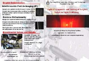
1 The Hong Kong University of Science and Technology Final Year Project presentation 2007 Project supervisor: Dr. Andrew Poon Department of Electronic and Computer Engineering Wong Ka Ki Chris, ee_wkkaf, Wong Tsz Ong Mark, ee_wto, Wong Tsz Ming Keith, ee_wtm,
2 Introduction

3 A B C Bottle A Bottle B Bottle C C A B? Bottle C Bottle A Bottle B
4 Project Objective Preliminary testing and sorting of droplets based on light scattering principles. Fast and non-intrusive such that the nature of sample would not be affected.


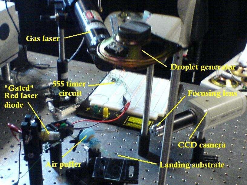
5 Droplet Generator. Pinhole STEP 1 vibrate Droplet filter Speaker Function Generator Gated Red Laser 60º CCD timer E CCD 2 STEP 3 42º Droplet Objective Lens To PC (Interferometic Particle Imaging ) STEP 2 To PC (Rainbow Refractometry) Air Puffer PC Data input from CCDs Glass Plate CCD 1 CCD 2 STEP 5 STEP 4 Wanted droplet Unwanted droplet Move using step motor Motor
6 System Flow Five Steps Approach [Step 1]: Droplet is produced by droplet generator. [Step 2]: Droplet size is determined by CCD1 (Interferometric Particle Imaging) [Step 3]: Droplet refractive index is determined by CCD2 (Rainbow Refractometry) [Step 4]: Computer analysis. [Step 5]: Unwanted droplets are sorted by air puffer
7 Project Advantages & Applications
8 Project Advantages Fast-testing Preliminary Result Non-intrusive Non Bio-Chemical
9 Applications Pharmaceutical Industries Medical Testing Bacteria Medicine Composition Industrial workplace Pigment

 Glass Plate Air")
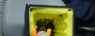
10 Droplet Generator. Pinhole Function Generator Upstream vibrate Speaker Droplet filter Gated Red Laser 60º CCD timer CCD 2 42º Droplet Objective Lens To PC (Interferometric Particle Imaging) Mid-stream Wanted droplet Unwanted droplet To PC (Rainbow Refractometry) Glass Plate Air Puffer Syringe Knob PC Data input from CCDs Down-stream Move using step motor Motor
11 Upstream
![Components [Droplet Generator] -Produces a stream of droplet samples](/docs-images/93/112168334/images/12-0.jpg "-Manual control of production rate [Droplet Filter] -Falling path")
12 Components [Droplet Generator] -Produces a stream of droplet samples -Manual control of production rate [Droplet Filter] -Falling path control


![ideas]: (1)](/docs-images/93/112168334/images/13-2.jpg "Syringe?")
 Dropper?")
13 Droplet Generator: To start [Primary ideas]: (1) Syringe? (2) Burette? (3) Dropper? (4) Spraying bottle?
![Droplet Generator: Structure [Building unit]:](/docs-images/93/112168334/images/14-0.jpg "(1) Loudspeaker (2) Syringe (3) Plastic tape")

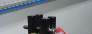
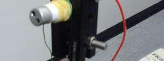
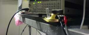
14 Droplet Generator: Structure [Building unit]: (1) Loudspeaker (2) Syringe (3) Plastic tape (4) Optical fiber (5) Function generator [Where does this idea come from?] [Building steps]


15 Droplet Generator: Performance Droplet production rate can be controlled by the function generator Droplet size is approximately 270µm in diameter [Problem]: - Falling path deviation - Plastic tape depreciation
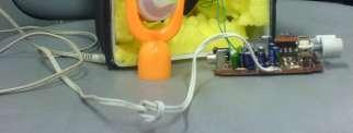
16 Droplet Filter [Any water-resistive materials / tools]: -Laser aperture control -Screw -Plastic taped surface with a tiny hole in the middle Video number: P
17 Mid-stream
![Components [Gated laser source] -Hitting the sample droplet to gives out scattering patterns -As a light](/docs-images/93/112168334/images/18-0.jpg "source for image capturing [CCD cameras] -Located at 42 0 and 60 0 respectively -Capture light scattering")
18 Components [Gated laser source] -Hitting the sample droplet to gives out scattering patterns -As a light source for image capturing [CCD cameras] -Located at 42 0 and 60 0 respectively -Capture light scattering patterns


19 Why Gated laser source?? Blurred images Overlapping of images even from a single sample droplet Limitation of the shutter s speed of the CCD camera

20 Gated laser source Stroboscopic Investigation technique Overlapping of images is resolved Pulse duration = 0.4µs
21 Image Capturing Two light scattering techniques were used: Droplet size measurement Interferometric Particle Imaging (IPI) Droplet Refractive Index determination Rainbow Refractometry What is Light Scattering?

 is called forward scattering region, whereas the remaining hemisphere is called backward scattering region.")
22 Light Scattering from Droplet Interaction of a laser beam with droplets is considered Incident plane wave k The laser is operated in the TEM00 mode creating a beam with a profile of Gaussian like y φ r x Detector When the droplet is comparably small to the diameter of the laser source, the Gaussian beam can be considered to be a plane wave The interaction between the laser beam and the droplet results in light scattering in all directions around the droplet Droplet θ z Scattering plane Polarization plane The scattered light can be captured by a receiver, for example, a CCD camera which is placed on the scattered plane The region with (0º θ 90º) is called forward scattering region, whereas the remaining hemisphere is called backward scattering region. The intensity distribution can be calculated with Lorenz-Mie Theory


23 Light Scattering from Droplet Forward Scattering Region Backward Scattering Region 2 nd rainbow 1 st rainbow Light Source Related intensity versus scattering angle Plotted by MiePlot. (n =1.334, λ =650nm, droplet diameter = 20µm) In the forward light scattering region, interference patterns with regular fringe spacing can be observed and part of this scattered light can be used to determine the Falling droplet droplet size. (Interferometric Particle Imaging) In the backward light scattering region, rainbow fringes are observed and they are droplet content dependent, for example texture and refractive index. (Rainbow Refractometry) Red Laser
24 Theories of Light scattering Why such intensity distribution comes out? If the droplet size is much smaller than the wavelength of the laser source (d << λ) Raleigh theory will be applied. If the droplet size a much larger than the wavelength of the laser source (d >> λ) geometrical optics will be applied However, geometrical optics does not provide an accurate result in scattering angles Lorenz-Mie theory. It works well for all droplets sizes and scattering angles. This theory came out from Lorenz (1890) and Mie (1908). It is a wave theory that is a solution of Maxwell s equations for Electromagnetic waves. Geometrical optics has deficits but it still helps to understand the light scattering phenomena Incident Light P = 0, Reflection droplet θ P = 1,1 st Refraction By Snell s law The 1st refraction is on the forward scattering region. The interference of these refracted lights together with the reflected light results in the regular interference fringes pattern While the scattered angle of different light rays from the 2nd refraction attains maximum at a certain angles, which is called rainbow angle P = 2, 2 nd Refraction

25 Rainbow Refractometry Refractive index is an important parameter for one to obtain additional information from a droplet Several laser-based techniques have been investigated. E.g. fluorescence and intensity-based light scattering Fluorescence: Additives are added and these pollute the droplet sample Intensity based light scattering: The intensity distribution of the scattered light is used to determine the droplet refractive index. E.g. Rainbow Refractometry The interference between internally reflected rays will induce a low frequency structure called Airy fringes. The interferences between internally and externally reflected rays will cause a high frequency structure called ripple structure superimposed on the Airy fringes Airy Theory Lorenz Mie theory Diameter: 200µm Refractive Index: 1.33 Wavelength: 650 nm Lorenz-Mie theory, we can compute the rainbow scattered by a single droplet. This helps us to determine the refractive index of the droplet

26 Rainbow Refractometry How the refractive index is determined? n = 1.33 n = 1.34 n = 1.35 The refractive index is determined from the absolute angular position of the interference pattern, the pattern shifts uniformly for about 1.5º when the refractive index changes by 0.1 Another method such as the relative intensity of the first few peak of the fringes of different are measured to obtain the refractive index. However, the pattern is size dependent, droplet size should be known Interferometric Particle Imaging (IPI)
27 Interferometric Particle Imaging (IPI) Technique used to measure droplet size Top View Non Focal Plane Focal plane 1 st refraction z Focused Image Droplet θ α da Reflection Aperture Red Laser Beam Lens Image Plane d = 2 λn msin( θ / 2) 1 α (cos( θ / 2) + m 2 ) 2mcos( θ / 2) + 1 N is the number of fringes, λ is the source wavelength, m is the refractive index of the liquid droplet, θ and α are the scattering and collecting angles, respectively. α is equivalent to the product of fringe number N and angular inter-spacing Δδ

28 Interferometric Particle Imaging (IPI) The dependence of the size measurement on the refractive index reduces to a minimum as a scattering angle of 60. In the other word, the diameter measurement is less dependent on the refractive index of the droplet. By measuring the number of fringes captured by a CCD camera non focused plane, droplet diameter can be obtained by the equation.
29 Down-stream
30 Sorting System Electrostatic Sorting Air Puffing
31 Electrostatic Wanted Cell Unwanted Cell
32 Electrostatic Implementation Difficulties Charge Injection High Voltage (Hazard)
33 Air Puffer Advantages: Relatively Safe Syringe Easy to Control Plastic membrane Needle

34 Air Puffer Real Time On Substrate Glass Plate Syringe Wanted droplet Unwanted droplet


35 Real Time Puffer Triggering signal Plastic membrane MP3 layer Amplifier magnet Loud Speaker 3W Syringe Needle


36 On Substrate Puffer Knob Plastic membrane nail Syringe Needle Motor
37 Result

38 Droplet size measurement Water, 3% glucose, 10 % glucose having different refractive index were measured. Number of interference fringes were counted by ImageJ. Using the equation from IPI, we can obtain the droplet size. Scattering angle of around 60 was used to obtain a lesser dependence of the refractive index on the droplet size measurement. In this experiment, λ = 650nm. α = rad and θ = 60º 10 samples were used for the calculation in each set of data. Water Refractive index is 1.33 at room temperature. Average number of fringes = 30.6 Droplet diameter = μm 42.0

39 Droplet size measurement 3% Glucose Solution Refractive index is at room temperature. Average number of fringes = 33.1 Droplet diameter = μm 10% Glucose Solution Refractive index is at room temperature. Average number of fringes = 33.8 Droplet diameter = μm

40 Droplet size measurement The average diameter of a falling droplet calculated by the IPI equation is 270.1μm, which is close to estimated droplet diameter from the photo.

")
41 Rainbow Refractometry P = 0, Reflection Droplet Incident Light P = 1,1 st Refraction θ P = 2, 2 nd Refraction (Rainbow Region) Backscattering


42 Rainbow Refractometry HeNe gas Laser Wavelength ~ 632.8nm Optical power ~ 20mW
43 Rainbow Refractometry

44 Rainbow Refractometry Droplet Intensity Measurement Relative Intensity Pixel (Distance)
 Contrast Ratio = (55/96) X 100% =")
45 Rainbow Refractometry Water (sample): Water Intensity Pixel (Distance) Contrast Ratio = (55/96) X 100% = 56%
 Contrast Ratio = (63/104) X 100% = 60.")
46 Rainbow Refractometry 10% Glucose Solution (sample): 10% Glucose Solution Intensity Pixel (Distance) Contrast Ratio = (63/104) X 100% = 60.5%
 Contrast Ratio = (73/110) X 100%")
47 Rainbow Refractometry 30% Glucose Solution (sample): 30% Glucose Solution Intensity Pixel (Distance) Contrast Ratio = (73/110) X 100% = 66.4%
48 Rainbow Refractometry Summary Table: Contrast Ratio Water 10% Glucose 30% Glucose captured photos for each solution 0
49 Rainbow Refractometry Water 10 % Glucose 30% Glucose
50 Rainbow Refractometry Frequency 12 Comparison Between Contrast Ratio Verus Differnent Aqeous Solution Water 10% Glucose Solution 30% Glucose Solution Contrast Ratio
51 Conclusions
52 Limitations Preliminary test Affected by air flow
53 Limitations
54 Eccentricity Limitations

55 Droplets Shape Limitations
56 Limitations Sensitivity ( n???) Solution Water 10% Glucose 30% Glucose Refractive Index 1.33?? Concentration = Mass of Glucose (g) Water Volume (ml) X 100%
57 Limitations Example. Slope = 2.5µ n/mg/dl g/ml mg/dl (10% Glucose) 1g/10mL mg/dl n = 0.025
58 Limitations Solution Refractive Index Water % Glucose % Glucose Sensitivity = 0.03
59 Improvement Smaller droplet can be generated by ink-jet printer Scattering angle detection can be used as an additional information to the change in refractive index The glass plate can be replaced by a Micro-fluidic cells that droplets can be further investigated bio-medically

60 Example on the usage of micro-fluidic cells Data from CCD Data from Micro-fluidic cell Microscope Air Puffer Output Signal Puff of air hydraulic pull Unwanted Droplet Wanted Droplet Micro-fluidic cells Light ray Diode

61 Contributions & Further work
62 Acknowledgements & Final Words
7 CHAPTER 7: REFRACTIVE INDEX MEASUREMENTS WITH COMMON PATH PHASE SENSITIVE FDOCT SETUP
 7 CHAPTER 7: REFRACTIVE INDEX MEASUREMENTS WITH COMMON PATH PHASE SENSITIVE FDOCT SETUP Abstract: In this chapter we describe the use of a common path phase sensitive FDOCT set up. The phase measurements
Exercise 8: Interference and diffraction
 Physics 223 Name: Exercise 8: Interference and diffraction 1. In a two-slit Young s interference experiment, the aperture (the mask with the two slits) to screen distance is 2.0 m, and a red light of wavelength
SPRAY DROPLET SIZE MEASUREMENT
 SPRAY DROPLET SIZE MEASUREMENT In this study, the PDA was used to characterize diesel and different blends of palm biofuel spray. The PDA is state of the art apparatus that needs no calibration. It is
Lithography. 3 rd. lecture: introduction. Prof. Yosi Shacham-Diamand. Fall 2004
 Lithography 3 rd lecture: introduction Prof. Yosi Shacham-Diamand Fall 2004 1 List of content Fundamental principles Characteristics parameters Exposure systems 2 Fundamental principles Aerial Image Exposure
EE119 Introduction to Optical Engineering Spring 2003 Final Exam. Name:
 EE119 Introduction to Optical Engineering Spring 2003 Final Exam Name: SID: CLOSED BOOK. THREE 8 1/2 X 11 SHEETS OF NOTES, AND SCIENTIFIC POCKET CALCULATOR PERMITTED. TIME ALLOTTED: 180 MINUTES Fundamental
Measurements of Droplets Spatial Distribution in Spray by Combining Focus and Defocus Images
 Measurements of Droplets Spatial Distribution in Spray by Combining Focus and Defocus Images Kentaro HAASHI 1*, Mitsuhisa ICHIANAGI 2, Koichi HISHIDA 3 1: Dept. of System Design Engineering, Keio University,
Applications of Optics
 Nicholas J. Giordano www.cengage.com/physics/giordano Chapter 26 Applications of Optics Marilyn Akins, PhD Broome Community College Applications of Optics Many devices are based on the principles of optics
Physics 431 Final Exam Examples (3:00-5:00 pm 12/16/2009) TIME ALLOTTED: 120 MINUTES Name: Signature:
 TIME ALLOTTED: 120 MINUTES Name: Signature:") Physics 431 Final Exam Examples (3:00-5:00 pm 12/16/2009) TIME ALLOTTED: 120 MINUTES Name: PID: Signature: CLOSED BOOK. TWO 8 1/2 X 11 SHEET OF NOTES (double sided is allowed), AND SCIENTIFIC POCKET CALCULATOR
Physics 431 Final Exam Examples (3:00-5:00 pm 12/16/2009) TIME ALLOTTED: 120 MINUTES Name: PID: Signature: CLOSED BOOK. TWO 8 1/2 X 11 SHEET OF NOTES (double sided is allowed), AND SCIENTIFIC POCKET CALCULATOR
Fiber Optic Communications
 Fiber Optic Communications ( Chapter 2: Optics Review ) presented by Prof. Kwang-Chun Ho 1 Section 2.4: Numerical Aperture Consider an optical receiver: where the diameter of photodetector surface area
Εισαγωγική στην Οπτική Απεικόνιση
 Εισαγωγική στην Οπτική Απεικόνιση Δημήτριος Τζεράνης, Ph.D. Εμβιομηχανική και Βιοϊατρική Τεχνολογία Τμήμα Μηχανολόγων Μηχανικών Ε.Μ.Π. Χειμερινό Εξάμηνο 2015 Light: A type of EM Radiation EM radiation:
Katarina Logg, Kristofer Bodvard, Mikael Käll. Dept. of Applied Physics. 12 September Optical Microscopy. Supervisor s signature:...
 Katarina Logg, Kristofer Bodvard, Mikael Käll Dept. of Applied Physics 12 September 2007 O1 Optical Microscopy Name:.. Date:... Supervisor s signature:... Introduction Over the past decades, the number
Physics 319 Laboratory: Optics
 1 Physics 319 Laboratory: Optics Birefringence II Objective: Previously, we have been concerned with the effect of linear polarizers on unpolarized and linearly polarized light. In this lab, we will explore
Diffractive Axicon application note
 Diffractive Axicon application note. Introduction 2. General definition 3. General specifications of Diffractive Axicons 4. Typical applications 5. Advantages of the Diffractive Axicon 6. Principle of
06SurfaceQuality.nb Optics James C. Wyant (2012) 1
 1") 06SurfaceQuality.nb Optics 513 - James C. Wyant (2012) 1 Surface Quality SQ-1 a) How is surface profile data obtained using the FECO interferometer? Your explanation should include diagrams with the appropriate
06SurfaceQuality.nb Optics 513 - James C. Wyant (2012) 1 Surface Quality SQ-1 a) How is surface profile data obtained using the FECO interferometer? Your explanation should include diagrams with the appropriate
<Chap. 2 Optics> 1.Light directivity. Light directivity can be seen using smoke and milky water in a plastic bottle
 1.Light directivity Light directivity can be seen using smoke and milky water in a plastic bottle Laser 3 cm Principle of pinhole camera (γray camera) Object Dark image Eye Ground glass
Be aware that there is no universal notation for the various quantities.
 Fourier Optics v2.4 Ray tracing is limited in its ability to describe optics because it ignores the wave properties of light. Diffraction is needed to explain image spatial resolution and contrast and
Design of a digital holographic interferometer for the. ZaP Flow Z-Pinch
 Design of a digital holographic interferometer for the M. P. Ross, U. Shumlak, R. P. Golingo, B. A. Nelson, S. D. Knecht, M. C. Hughes, R. J. Oberto University of Washington, Seattle, USA Abstract The
Computer Generated Holograms for Optical Testing
 Computer Generated Holograms for Optical Testing Dr. Jim Burge Associate Professor Optical Sciences and Astronomy University of Arizona jburge@optics.arizona.edu 520-621-8182 Computer Generated Holograms
ADVANCED OPTICS LAB -ECEN 5606
 ADVANCED OPTICS LAB -ECEN 5606 Basic Skills Lab Dr. Steve Cundiff and Edward McKenna, 1/15/04 rev KW 1/15/06, 1/8/10 The goal of this lab is to provide you with practice of some of the basic skills needed
OPAC 202 Optical Design and Instrumentation. Topic 3 Review Of Geometrical and Wave Optics. Department of
 OPAC 202 Optical Design and Instrumentation Topic 3 Review Of Geometrical and Wave Optics Department of http://www.gantep.edu.tr/~bingul/opac202 Optical & Acustical Engineering Gaziantep University Feb
Fiberoptic and Waveguide Sensors
 Fiberoptic and Waveguide Sensors Wei-Chih Wang Department of Mecahnical Engineering University of Washington Optical sensors Advantages: -immune from electromagnetic field interference (EMI) - extreme
Chapter 7. Optical Measurement and Interferometry
 Chapter 7 Optical Measurement and Interferometry 1 Introduction Optical measurement provides a simple, easy, accurate and reliable means for carrying out inspection and measurements in the industry the
1.6 Beam Wander vs. Image Jitter
 8 Chapter 1 1.6 Beam Wander vs. Image Jitter It is common at this point to look at beam wander and image jitter and ask what differentiates them. Consider a cooperative optical communication system that
PHY 431 Homework Set #5 Due Nov. 20 at the start of class
 PHY 431 Homework Set #5 Due Nov. 0 at the start of class 1) Newton s rings (10%) The radius of curvature of the convex surface of a plano-convex lens is 30 cm. The lens is placed with its convex side down
2. Refraction and Reflection
 2. Refraction and Reflection In this lab we will observe the displacement of a light beam by a parallel plate due to refraction. We will determine the refractive index of some liquids from the incident
EE119 Introduction to Optical Engineering Spring 2002 Final Exam. Name:
 EE119 Introduction to Optical Engineering Spring 2002 Final Exam Name: SID: CLOSED BOOK. FOUR 8 1/2 X 11 SHEETS OF NOTES, AND SCIENTIFIC POCKET CALCULATOR PERMITTED. TIME ALLOTTED: 180 MINUTES Fundamental
LOS 1 LASER OPTICS SET
 LOS 1 LASER OPTICS SET Contents 1 Introduction 3 2 Light interference 5 2.1 Light interference on a thin glass plate 6 2.2 Michelson s interferometer 7 3 Light diffraction 13 3.1 Light diffraction on a
FRAUNHOFER AND FRESNEL DIFFRACTION IN ONE DIMENSION
 FRAUNHOFER AND FRESNEL DIFFRACTION IN ONE DIMENSION Revised November 15, 2017 INTRODUCTION The simplest and most commonly described examples of diffraction and interference from two-dimensional apertures
Fabrication of Probes for High Resolution Optical Microscopy
 Fabrication of Probes for High Resolution Optical Microscopy Physics 564 Applied Optics Professor Andrès La Rosa David Logan May 27, 2010 Abstract Near Field Scanning Optical Microscopy (NSOM) is a technique
Chapter Ray and Wave Optics
 109 Chapter Ray and Wave Optics 1. An astronomical telescope has a large aperture to [2002] reduce spherical aberration have high resolution increase span of observation have low dispersion. 2. If two
ADVANCED OPTICS LAB -ECEN Basic Skills Lab
 ADVANCED OPTICS LAB -ECEN 5606 Basic Skills Lab Dr. Steve Cundiff and Edward McKenna, 1/15/04 Revised KW 1/15/06, 1/8/10 Revised CC and RZ 01/17/14 The goal of this lab is to provide you with practice
Observational Astronomy
 Observational Astronomy Instruments The telescope- instruments combination forms a tightly coupled system: Telescope = collecting photons and forming an image Instruments = registering and analyzing the
Single-photon excitation of morphology dependent resonance
 Single-photon excitation of morphology dependent resonance 3.1 Introduction The examination of morphology dependent resonance (MDR) has been of considerable importance to many fields in optical science.
Week IX: INTERFEROMETER EXPERIMENTS
 Week IX: INTERFEROMETER EXPERIMENTS Notes on Adjusting the Michelson Interference Caution: Do not touch the mirrors or beam splitters they are front surface and difficult to clean without damaging them.
Optical Fiber Technology. Photonic Network By Dr. M H Zaidi
 Optical Fiber Technology Numerical Aperture (NA) What is numerical aperture (NA)? Numerical aperture is the measure of the light gathering ability of optical fiber The higher the NA, the larger the core
3.0 Alignment Equipment and Diagnostic Tools:
 3.0 Alignment Equipment and Diagnostic Tools: Alignment equipment The alignment telescope and its use The laser autostigmatic cube (LACI) interferometer A pin -- and how to find the center of curvature
Absolute distance interferometer in LaserTracer geometry
 Absolute distance interferometer in LaserTracer geometry Corresponding author: Karl Meiners-Hagen Abstract 1. Introduction 1 In this paper, a combination of variable synthetic and two-wavelength interferometry
Experiment 1: Fraunhofer Diffraction of Light by a Single Slit
 Experiment 1: Fraunhofer Diffraction of Light by a Single Slit Purpose 1. To understand the theory of Fraunhofer diffraction of light at a single slit and at a circular aperture; 2. To learn how to measure
Examination Optoelectronic Communication Technology. April 11, Name: Student ID number: OCT1 1: OCT 2: OCT 3: OCT 4: Total: Grade:
 Examination Optoelectronic Communication Technology April, 26 Name: Student ID number: OCT : OCT 2: OCT 3: OCT 4: Total: Grade: Declaration of Consent I hereby agree to have my exam results published on
EXPRIMENT 3 COUPLING FIBERS TO SEMICONDUCTOR SOURCES
 EXPRIMENT 3 COUPLING FIBERS TO SEMICONDUCTOR SOURCES OBJECTIVES In this lab, firstly you will learn to couple semiconductor sources, i.e., lightemitting diodes (LED's), to optical fibers. The coupling
The Henryk Niewodniczański INSTITUTE OF NUCLEAR PHYSICS Polish Academy of Sciences ul. Radzikowskiego 152, Kraków, Poland.
 The Henryk Niewodniczański INSTITUTE OF NUCLEAR PHYSICS Polish Academy of Sciences ul. Radzikowskiego 152, 31-342 Kraków, Poland. www.ifj.edu.pl/reports/2003.html Kraków, grudzień 2003 Report No 1931/PH
PHYS 3153 Methods of Experimental Physics II O2. Applications of Interferometry
 Purpose PHYS 3153 Methods of Experimental Physics II O2. Applications of Interferometry In this experiment, you will study the principles and applications of interferometry. Equipment and components PASCO
Test procedures Page: 1 of 5
 Test procedures Page: 1 of 5 1 Scope This part of document establishes uniform requirements for measuring the numerical aperture of optical fibre, thereby assisting in the inspection of fibres and cables
Fabry-Perot Interferometer
 Experimental Optics Contact: Maximilian Heck (maximilian.heck@uni-jena.de) Ria Krämer (ria.kraemer@uni-jena.de) Last edition: Ria Krämer, March 2017 Fabry-Perot Interferometer Contents 1 Overview 3 2 Safety
Fiber Optic Communications Communication Systems
 INTRODUCTION TO FIBER-OPTIC COMMUNICATIONS A fiber-optic system is similar to the copper wire system in many respects. The difference is that fiber-optics use light pulses to transmit information down
Observing Microorganisms through a Microscope LIGHT MICROSCOPY: This type of microscope uses visible light to observe specimens. Compound Light Micros
 PHARMACEUTICAL MICROBIOLOGY JIGAR SHAH INSTITUTE OF PHARMACY NIRMA UNIVERSITY Observing Microorganisms through a Microscope LIGHT MICROSCOPY: This type of microscope uses visible light to observe specimens.
Femtosecond laser microfabrication in. Prof. Dr. Cleber R. Mendonca
 Femtosecond laser microfabrication in polymers Prof. Dr. Cleber R. Mendonca laser microfabrication focus laser beam on material s surface laser microfabrication laser microfabrication laser microfabrication
Testing Aspheric Lenses: New Approaches
 Nasrin Ghanbari OPTI 521 - Synopsis of a published Paper November 5, 2012 Testing Aspheric Lenses: New Approaches by W. Osten, B. D orband, E. Garbusi, Ch. Pruss, and L. Seifert Published in 2010 Introduction
7. Michelson Interferometer
 7. Michelson Interferometer In this lab we are going to observe the interference patterns produced by two spherical waves as well as by two plane waves. We will study the operation of a Michelson interferometer,
Will contain image distance after raytrace Will contain image height after raytrace
 Name: LASR 51 Final Exam May 29, 2002 Answer all questions. Module numbers are for guidance, some material is from class handouts. Exam ends at 8:20 pm. Ynu Raytracing The first questions refer to the
1. Evolution Of Fiber Optic Systems
 OPTICAL FIBER COMMUNICATION UNIT-I : OPTICAL FIBERS STRUCTURE: 1. Evolution Of Fiber Optic Systems The operating range of optical fiber system term and the characteristics of the four key components of
Resolution. Diffraction from apertures limits resolution. Rayleigh criterion θ Rayleigh = 1.22 λ/d 1 peak at 2 nd minimum. θ f D
 Microscopy Outline 1. Resolution and Simple Optical Microscope 2. Contrast enhancement: Dark field, Fluorescence (Chelsea & Peter), Phase Contrast, DIC 3. Newer Methods: Scanning Tunneling microscopy (STM),
Dynamic beam shaping with programmable diffractive optics
 Dynamic beam shaping with programmable diffractive optics Bosanta R. Boruah Dept. of Physics, GU Page 1 Outline of the talk Introduction Holography Programmable diffractive optics Laser scanning confocal
Synthesis of projection lithography for low k1 via interferometry
 Synthesis of projection lithography for low k1 via interferometry Frank Cropanese *, Anatoly Bourov, Yongfa Fan, Andrew Estroff, Lena Zavyalova, Bruce W. Smith Center for Nanolithography Research, Rochester
7 WAVEMETER PROJECT #6 MODEL OEK-100. Measure the Wavelength of An Unknown laser Using 633nm and 543 nm HeNe lasers
 7 WAVEMETER Measure the Wavelength of An Unknown laser Using 633nm and 543 nm HeNe lasers MODEL OEK-100 PROJECT #6 72 7.1 Introduction A wavemeter can be constructed with a Twyman-Green interferometer.
Application of Interferometric Laser Imaging Technique to a Transient Spray Flow.
 Application of Interferometric Laser Imaging Technique to a Transient Spray Flow. by Yukihiro AKASAKA, Tatsuya KAWAGUCHI, Masanobu MAEDA Abstract Department of System Design Engineering, Keio University,
Confocal Microscopy and Related Techniques
 Confocal Microscopy and Related Techniques Chau-Hwang Lee Associate Research Fellow Research Center for Applied Sciences, Academia Sinica 128 Sec. 2, Academia Rd., Nankang, Taipei 11529, Taiwan E-mail:
Section 1: Sound. Sound and Light Section 1
 Sound and Light Section 1 Section 1: Sound Preview Key Ideas Bellringer Properties of Sound Sound Intensity and Decibel Level Musical Instruments Hearing and the Ear The Ear Ultrasound and Sonar Sound
LENSES. INEL 6088 Computer Vision
 LENSES INEL 6088 Computer Vision Digital camera A digital camera replaces film with a sensor array Each cell in the array is a Charge Coupled Device light-sensitive diode that converts photons to electrons
Fastest high definition Raman imaging. Fastest Laser Raman Microscope RAMAN
 Fastest high definition Raman imaging Fastest Laser Raman Microscope RAMAN - 11 www.nanophoton.jp Observation A New Generation in Raman Observation RAMAN-11 developed by Nanophoton was newly created by
Chapter 17: Wave Optics. What is Light? The Models of Light 1/11/13
 Chapter 17: Wave Optics Key Terms Wave model Ray model Diffraction Refraction Fringe spacing Diffraction grating Thin-film interference What is Light? Light is the chameleon of the physical world. Under
Comparison of FRD (Focal Ratio Degradation) for Optical Fibres with Different Core Sizes By Neil Barrie
 for Optical Fibres with Different Core Sizes By Neil Barrie") Comparison of FRD (Focal Ratio Degradation) for Optical Fibres with Different Core Sizes By Neil Barrie Introduction The purpose of this experimental investigation was to determine whether there is a dependence
Comparison of FRD (Focal Ratio Degradation) for Optical Fibres with Different Core Sizes By Neil Barrie Introduction The purpose of this experimental investigation was to determine whether there is a dependence
Lab in a Box Microwave Interferometer
 In 1887 Michelson and Morley used an optical interferometer (a device invented by Michelson to accurately detect aether flow) to try and detect the relative motion of light through the luminous either.
3D Optical Motion Analysis of Micro Systems. Heinrich Steger, Polytec GmbH, Waldbronn
 3D Optical Motion Analysis of Micro Systems Heinrich Steger, Polytec GmbH, Waldbronn SEMICON Europe 2012 Outline Needs and Challenges of measuring Micro Structure and MEMS Tools and Applications for optical
Examination, TEN1, in courses SK2500/SK2501, Physics of Biomedical Microscopy,
 KTH Applied Physics Examination, TEN1, in courses SK2500/SK2501, Physics of Biomedical Microscopy, 2009-06-05, 8-13, FB51 Allowed aids: Compendium Imaging Physics (handed out) Compendium Light Microscopy
EE119 Introduction to Optical Engineering Fall 2009 Final Exam. Name:
 EE119 Introduction to Optical Engineering Fall 2009 Final Exam Name: SID: CLOSED BOOK. THREE 8 1/2 X 11 SHEETS OF NOTES, AND SCIENTIFIC POCKET CALCULATOR PERMITTED. TIME ALLOTTED: 180 MINUTES Fundamental
TSBB09 Image Sensors 2018-HT2. Image Formation Part 1
 TSBB09 Image Sensors 2018-HT2 Image Formation Part 1 Basic physics Electromagnetic radiation consists of electromagnetic waves With energy That propagate through space The waves consist of transversal
Optical Coherence: Recreation of the Experiment of Thompson and Wolf
 Optical Coherence: Recreation of the Experiment of Thompson and Wolf David Collins Senior project Department of Physics, California Polytechnic State University San Luis Obispo June 2010 Abstract The purpose
Chapter Wave Optics. MockTime.com. Ans: (d)
") Chapter Wave Optics Q1. Which one of the following phenomena is not explained by Huygen s construction of wave front? [1988] (a) Refraction Reflection Diffraction Origin of spectra Q2. Which of the following
Chapter Wave Optics Q1. Which one of the following phenomena is not explained by Huygen s construction of wave front? [1988] (a) Refraction Reflection Diffraction Origin of spectra Q2. Which of the following
Optical Components for Laser Applications. Günter Toesko - Laserseminar BLZ im Dezember
 Günter Toesko - Laserseminar BLZ im Dezember 2009 1 Aberrations An optical aberration is a distortion in the image formed by an optical system compared to the original. It can arise for a number of reasons
Speed of light E Introduction
 Notice: All measurements and calculated values must be presented with SI units with an appropriate number of significant digits. Uncertainties required only when explicitly asked for. 1.0 Introduction
Photolithography II ( Part 2 )
") 1 Photolithography II ( Part 2 ) Chapter 14 : Semiconductor Manufacturing Technology by M. Quirk & J. Serda Saroj Kumar Patra, Department of Electronics and Telecommunication, Norwegian University of Science
1 Photolithography II ( Part 2 ) Chapter 14 : Semiconductor Manufacturing Technology by M. Quirk & J. Serda Saroj Kumar Patra, Department of Electronics and Telecommunication, Norwegian University of Science
attosnom I: Topography and Force Images NANOSCOPY APPLICATION NOTE M06 RELATED PRODUCTS G
 APPLICATION NOTE M06 attosnom I: Topography and Force Images Scanning near-field optical microscopy is the outstanding technique to simultaneously measure the topography and the optical contrast of a sample.
Lecture 15: Fraunhofer diffraction by a circular aperture
 Lecture 15: Fraunhofer diffraction by a circular aperture Lecture aims to explain: 1. Diffraction problem for a circular aperture 2. Diffraction pattern produced by a circular aperture, Airy rings 3. Importance
Collimation Tester Instructions
 Description Use shear-plate collimation testers to examine and adjust the collimation of laser light, or to measure the wavefront curvature and divergence/convergence magnitude of large-radius optical
Microscopic Laser Doppler Vibrometer
 Microscopic Laser Doppler Vibrometer System Configuration - 1 PC Controller (APU-Analog processing unit, DPU-Digital processing unit) Optic Head (MEMS Type, XS Type) Function Generator Power Supply Testing
Experimental Physics. Experiment C & D: Pulsed Laser & Dye Laser. Course: FY12. Project: The Pulsed Laser. Done by: Wael Al-Assadi & Irvin Mangwiza
 Experiment C & D: Course: FY1 The Pulsed Laser Done by: Wael Al-Assadi Mangwiza 8/1/ Wael Al Assadi Mangwiza Experiment C & D : Introduction: Course: FY1 Rev. 35. Page: of 16 1// In this experiment we
LECTURE 13 DIFFRACTION. Instructor: Kazumi Tolich
 LECTURE 13 DIFFRACTION Instructor: Kazumi Tolich Lecture 13 2 Reading chapter 33-4 & 33-6 to 33-7 Single slit diffraction Two slit interference-diffraction Fraunhofer and Fresnel diffraction Diffraction
PHYS 202 OUTLINE FOR PART III LIGHT & OPTICS
 PHYS 202 OUTLINE FOR PART III LIGHT & OPTICS Electromagnetic Waves A. Electromagnetic waves S-23,24 1. speed of waves = 1/( o o ) ½ = 3 x 10 8 m/s = c 2. waves and frequency: the spectrum (a) radio red
3B SCIENTIFIC PHYSICS
 3B SCIENTIFIC PHYSICS Equipment Set for Wave Optics with Laser U17303 Instruction sheet 10/08 Alf 1. Safety instructions The laser emits visible radiation at a wavelength of 635 nm with a maximum power
Mirrors and Lenses. Images can be formed by reflection from mirrors. Images can be formed by refraction through lenses.
 Mirrors and Lenses Images can be formed by reflection from mirrors. Images can be formed by refraction through lenses. Notation for Mirrors and Lenses The object distance is the distance from the object
Holography. Introduction
 Holography Introduction Holography is the technique of using monochromatic light sources to produce 3D images on photographic film or specially designed plates. In this experiment you will learn about
a) How big will that physical image of the cells be your camera sensor?
 How big will that physical image of the cells be your camera sensor?") 1. Consider a regular wide-field microscope set up with a 60x, NA = 1.4 objective and a monochromatic digital camera with 8 um pixels, properly positioned in the primary image plane. This microscope is
1. Consider a regular wide-field microscope set up with a 60x, NA = 1.4 objective and a monochromatic digital camera with 8 um pixels, properly positioned in the primary image plane. This microscope is
PHYSICS. Chapter 35 Lecture FOR SCIENTISTS AND ENGINEERS A STRATEGIC APPROACH 4/E RANDALL D. KNIGHT
 PHYSICS FOR SCIENTISTS AND ENGINEERS A STRATEGIC APPROACH 4/E Chapter 35 Lecture RANDALL D. KNIGHT Chapter 35 Optical Instruments IN THIS CHAPTER, you will learn about some common optical instruments and
=, where f is focal length of a lens (positive for convex. Equations: Lens equation
 Physics 1230 Light and Color : Exam #1 Your full name: Last First & middle General information: This exam will be worth 100 points. There are 10 multiple choice questions worth 5 points each (part 1 of
Diffraction Coronae. Ian Jacobs, Physics advisor, KVIS, Rayong, Thailand
 Diffraction Coronae Ian Jacobs, Physics advisor, KVIS, Rayong, Thailand Coronae are diffraction rings around the sun or moon due to water droplets, pollen or ice at high altitudes. The name is from Greek
Shaping light in microscopy:
 Shaping light in microscopy: Adaptive optical methods and nonconventional beam shapes for enhanced imaging Martí Duocastella planet detector detector sample sample Aberrated wavefront Beamsplitter Adaptive
SUBJECT: PHYSICS. Use and Succeed.
 SUBJECT: PHYSICS I hope this collection of questions will help to test your preparation level and useful to recall the concepts in different areas of all the chapters. Use and Succeed. Navaneethakrishnan.V
Polarization Experiments Using Jones Calculus
 Polarization Experiments Using Jones Calculus Reference http://chaos.swarthmore.edu/courses/physics50_2008/p50_optics/04_polariz_matrices.pdf Theory In Jones calculus, the polarization state of light is
Using Stock Optics. ECE 5616 Curtis
 Using Stock Optics What shape to use X & Y parameters Please use achromatics Please use camera lens Please use 4F imaging systems Others things Data link Stock Optics Some comments Advantages Time and
FDTD Analysis of Readout Characteristics in a near-field MAMMOS recording system. Matthew Manfredonia Paul Nutter & David Wright
 FDTD Analysis of Readout Characteristics in a near-field MAMMOS recording system Matthew Manfredonia Paul Nutter & David Wright Electronic & Information Storage Systems Research Group School of Computer
Laser Beam Analysis Using Image Processing
 Journal of Computer Science 2 (): 09-3, 2006 ISSN 549-3636 Science Publications, 2006 Laser Beam Analysis Using Image Processing Yas A. Alsultanny Computer Science Department, Amman Arab University for
Supplementary Figure 1. Effect of the spacer thickness on the resonance properties of the gold and silver metasurface layers.
 Supplementary Figure 1. Effect of the spacer thickness on the resonance properties of the gold and silver metasurface layers. Finite-difference time-domain calculations of the optical transmittance through
Supplementary Information for. Surface Waves. Angelo Angelini, Elsie Barakat, Peter Munzert, Luca Boarino, Natascia De Leo,
 Supplementary Information for Focusing and Extraction of Light mediated by Bloch Surface Waves Angelo Angelini, Elsie Barakat, Peter Munzert, Luca Boarino, Natascia De Leo, Emanuele Enrico, Fabrizio Giorgis,
Fabrication of microstructures on photosensitive glass using a femtosecond laser process and chemical etching
 Fabrication of microstructures on photosensitive glass using a femtosecond laser process and chemical etching C. W. Cheng* 1, J. S. Chen* 2, P. X. Lee* 2 and C. W. Chien* 1 *1 ITRI South, Industrial Technology
VISUAL PHYSICS ONLINE DEPTH STUDY: ELECTRON MICROSCOPES
 VISUAL PHYSICS ONLINE DEPTH STUDY: ELECTRON MICROSCOPES Shortly after the experimental confirmation of the wave properties of the electron, it was suggested that the electron could be used to examine objects
UNIT Write notes on broadening of pulse in the fiber dispersion?
 UNIT 3 1. Write notes on broadening of pulse in the fiber dispersion? Ans: The dispersion of the transmitted optical signal causes distortion for both digital and analog transmission along optical fibers.
The below identified patent application is available for licensing. Requests for information should be addressed to:
 DEPARTMENT OF THE NAVY OFFICE OF COUNSEL NAVAL UNDERSEA WARFARE CENTER DIVISION 1176 HOWELL STREET NEWPORT Rl 0841-1708 IN REPLY REFER TO Attorney Docket No. 300048 7 February 017 The below identified
COLOUR INSPECTION, INFRARED AND UV
 COLOUR INSPECTION, INFRARED AND UV TIPS, SPECIAL FEATURES, REQUIREMENTS LARS FERMUM, CHIEF INSTRUCTOR, STEMMER IMAGING THE PROPERTIES OF LIGHT Light is characterized by specifying the wavelength, amplitude
Fast Laser Raman Microscope RAMAN
 Fast Laser Raman Microscope RAMAN - 11 www.nanophoton.jp Fast Raman Imaging A New Generation of Raman Microscope RAMAN-11 developed by Nanophoton was created by combining confocal laser microscope technology