Chapter 7. Optical Measurement and Interferometry
|
|
|
- Loraine Moody
- 6 years ago
- Views:
Transcription
1 Chapter 7 Optical Measurement and Interferometry 1
2 Introduction Optical measurement provides a simple, easy, accurate and reliable means for carrying out inspection and measurements in the industry the projected image should be clear, sharp and dimensionally accurate. Application of interference of light is extreme interest in metrology Lasers are also being increasingly used in interferometers for precision measurement. 2
3 Optical Measurement Techniques Optical magnification is one of the most widely used techniques in metrology. the primary requirement is visual magnification of small objects to a high degree with the additional provision for taking measurements. 3


4 Tool Maker s Microscope A tool maker s microscope supports a wide range of applications from shop floor inspection, measurement of tools and machined parts, to precision measurement of test tools in a measuring room. 4


5 Tool Maker s Microscope 5
6 Tool Maker s Microscope It features a vertical supporting column, which is robust and carries the weight of all other parts of the microscope The work piece is loaded on an XY stage, which has provision for translatory motion in two principal directions in the horizontal plane The entire optical system is housed in the measuring head When the image is viewed through the eye piece, a reticle provides the reference or datum to facilitate measurement 6
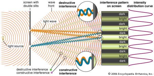
7 Optical Interference When two light waves interact with each other, the wave effect leads to the phenomenon called interference of light. The instruments designed to measure with interference are known as interferometers. Let us consider two monochromatic light rays from the same light source, but originating from two point sources A and B. the distances AO 1 and BO 1 are equal, the two rays are in phase, and results in maximum illumination at point O 1. On the other hand, at point O 2, the distance BO 2 is longer than the distance AO 2. Therefore, by the time the two rays arrive at the point O 2, they are out of phase Suppose the phase difference δ = λ / 2, where λ is the wave length of light, then it leads to complete interference and formation of a dark spot. 7

8 Optical Interference This process repeats on either side of O 1 on the screen, resulting in the formation of alternate dark and bright areas. 8
9 Optical Interference 9
10 Interferometry The phenomenon of interference is made use of for carrying out precise measurements of very small linear dimensions, and the measurement technique is popularly known as interferometry. This technique is used in a variety of metrological applications such as inspection of machine parts for straightness, parallelism, flatness, measurement of very small diameters, and so on. The instrument used for making measurements using interferometry technique is called an interferometer. 10

11 Optical Flats 11
12 Optical Flats An optical flat is a disk of high quality glass or quartz When an optical flat is laid over a flat reflecting surface, it orients at a small angle θ, because of the presence of air damper between the two surfaces. When light from a monochromatic light source is made to fall on an optical flat, which is oriented at a very small angle with respect to a flat reflecting surface, alternate band of light and dark patches are seen by the eye In case of a perfectly flat surface, the fringe pattern is regular, parallel and uniformly spaced. Any deviation from this pattern is a measure of error in the flatness of the surface being measured 12

 in")
13 Optical Flats Optical flats in case. About 1 inch (2.5 cm) in diameter 13

14 Optical Flats Fig. shows photos of reference flats being used to check two test flats at different stages of completion, showing the different patterns of interference fringes. The reference flats are resting with their bottom surfaces in contact with the test flats, and they are illuminated by a monochromatic light source. The light waves reflected from both surfaces interfere, resulting in a pattern of bright and dark bands. The surface in the left photo is nearly flat, indicated by a pattern of straight parallel interference fringes at equal intervals. The surface in the right photo is uneven, resulting in a pattern of curved fringes. 14
15 Interferometers Whereas an interferometer works on the same basic principle as that of an optical flat, it is provided with arrangements in order to control the lay and orientation of fringes. It is also provided with a viewing or recording system, which eliminates the measurement errors. 15

16 N.P.L Flatness Interferometer The light from a mercury vapour lamp is condensed and passed through a green filter, resulting in a green monochromatic light source. The light will now pass through a pin hole, giving an intense point source of monochromatic light. The pin hole is positioned such that it is in the focal plane of a collimating lens. Therefore, the collimating lens projects a parallel beam of light on to the face of the gauge to be tested via an optical flat. This results in the formation of interference fringes. NPL: National Physical Laboratory, UK 16

17 N.P.L Flatness Interferometer 17


18 Laser Interferometers Interference fringes can be observed with a light intensity that is 1000 times more than any other monochromatic light source. 18
19 Laser Interferometers In interferometry, laser light exhibits similar properties as that of any normal light. The fixed unit called the laser head consists of laser, a pair of semireflectors and two photo diodes. The sliding unit will have a corner cube mounted on it. The corner cube is a glass disk whose back surface has three polished faces mutually at right angles to each other. The photo diodes will electronically measure the fringe intensity and provide an accurate means for measuring displacement. 19
 it uses the very small, stable and accurately defined wavelength of laser as a unit of measure.")
20 Laser Interferometers the instrument used for high precision measurements (distance, angles. etc.) it uses the very small, stable and accurately defined wavelength of laser as a unit of measure. 20

21 Laser Interferometers Other Applications flatness, straightness, velocity and vibrations, etc. Source: Loudspeaker vibrating at 1500 Hz 21
Physics 1520, Spring 2013 Quiz 2, Form: A
 Physics 1520, Spring 2013 Quiz 2, Form: A Name: Date: Section 1. Exercises 1. The index of refraction of a certain type of glass for red light is 1.52. For violet light, it is 1.54. Which color of light,
Laser Telemetric System (Metrology)
") Laser Telemetric System (Metrology) Laser telemetric system is a non-contact gauge that measures with a collimated laser beam (Refer Fig. 10.26). It measure at the rate of 150 scans per second. It basically
Laser Telemetric System (Metrology) Laser telemetric system is a non-contact gauge that measures with a collimated laser beam (Refer Fig. 10.26). It measure at the rate of 150 scans per second. It basically
Mirrors and Lenses. Images can be formed by reflection from mirrors. Images can be formed by refraction through lenses.
 Mirrors and Lenses Images can be formed by reflection from mirrors. Images can be formed by refraction through lenses. Notation for Mirrors and Lenses The object distance is the distance from the object
PHYS General Physics II Lab Diffraction Grating
 1 PHYS 1040 - General Physics II Lab Diffraction Grating In this lab you will perform an experiment to understand the interference of light waves when they pass through a diffraction grating and to determine
Chapter Ray and Wave Optics
 109 Chapter Ray and Wave Optics 1. An astronomical telescope has a large aperture to [2002] reduce spherical aberration have high resolution increase span of observation have low dispersion. 2. If two
PRINCIPLE PROCEDURE ACTIVITY. AIM To observe diffraction of light due to a thin slit.
 ACTIVITY 12 AIM To observe diffraction of light due to a thin slit. APPARATUS AND MATERIAL REQUIRED Two razor blades, one adhesive tape/cello-tape, source of light (electric bulb/ laser pencil), a piece
PHY 431 Homework Set #5 Due Nov. 20 at the start of class
 PHY 431 Homework Set #5 Due Nov. 0 at the start of class 1) Newton s rings (10%) The radius of curvature of the convex surface of a plano-convex lens is 30 cm. The lens is placed with its convex side down
Chapter 34 The Wave Nature of Light; Interference. Copyright 2009 Pearson Education, Inc.
 Chapter 34 The Wave Nature of Light; Interference 34-7 Luminous Intensity The intensity of light as perceived depends not only on the actual intensity but also on the sensitivity of the eye at different
Understanding Optical Specifications
 Understanding Optical Specifications Optics can be found virtually everywhere, from fiber optic couplings to machine vision imaging devices to cutting-edge biometric iris identification systems. Despite
PhysicsAndMathsTutor.com 1
 PhysicsAndMathsTutor.com 1 Q1. Just over two hundred years ago Thomas Young demonstrated the interference of light by illuminating two closely spaced narrow slits with light from a single light source.
EXPERIMENT 4 INVESTIGATIONS WITH MIRRORS AND LENSES 4.2 AIM 4.1 INTRODUCTION
 EXPERIMENT 4 INVESTIGATIONS WITH MIRRORS AND LENSES Structure 4.1 Introduction 4.2 Aim 4.3 What is Parallax? 4.4 Locating Images 4.5 Investigations with Real Images Focal Length of a Concave Mirror Focal
Practice Problems for Chapter 25-26
 Practice Problems for Chapter 25-26 1. What are coherent waves? 2. Describe diffraction grating 3. What are interference fringes? 4. What does monochromatic light mean? 5. What does the Rayleigh Criterion
Optical System Design
 Phys 531 Lecture 12 14 October 2004 Optical System Design Last time: Surveyed examples of optical systems Today, discuss system design Lens design = course of its own (not taught by me!) Try to give some
Unit-23 Michelson Interferometer I
 Unit-23 Michelson Interferometer I Objective: Study the theory and the design of Michelson Interferometer. And use it to measure the wavelength of a light source. Apparatus: Michelson interferometer (include
Image Formation. Light from distant things. Geometrical optics. Pinhole camera. Chapter 36
 Light from distant things Chapter 36 We learn about a distant thing from the light it generates or redirects. The lenses in our eyes create images of objects our brains can process. This chapter concerns
Difrotec Product & Services. Ultra high accuracy interferometry & custom optical solutions
 Difrotec Product & Services Ultra high accuracy interferometry & custom optical solutions Content 1. Overview 2. Interferometer D7 3. Benefits 4. Measurements 5. Specifications 6. Applications 7. Cases
AS Physics Unit 5 - Waves 1
 AS Physics Unit 5 - Waves 1 WHAT IS WAVE MOTION? The wave motion is a means of transferring energy from one point to another without the transfer of any matter between the points. Waves may be classified
Option G 4:Diffraction
 Name: Date: Option G 4:Diffraction 1. This question is about optical resolution. The two point sources shown in the diagram below (not to scale) emit light of the same frequency. The light is incident
FRAUNHOFER AND FRESNEL DIFFRACTION IN ONE DIMENSION
 FRAUNHOFER AND FRESNEL DIFFRACTION IN ONE DIMENSION Revised November 15, 2017 INTRODUCTION The simplest and most commonly described examples of diffraction and interference from two-dimensional apertures
Class XII - Physics Wave Optics Chapter-wise Problems
 Class XII - hysics Wave Optics Chapter-wise roblems Multiple Choice Question :- 10.1 Consider a light beam incident from air to a glass slab at Brewster s angle as shown in Fig. 10.1. A polaroid is placed
Exercise 8: Interference and diffraction
 Physics 223 Name: Exercise 8: Interference and diffraction 1. In a two-slit Young s interference experiment, the aperture (the mask with the two slits) to screen distance is 2.0 m, and a red light of wavelength
OPTICS DIVISION B. School/#: Names:
 OPTICS DIVISION B School/#: Names: Directions: Fill in your response for each question in the space provided. All questions are worth two points. Multiple Choice (2 points each question) 1. Which of the
Optical Coherence: Recreation of the Experiment of Thompson and Wolf
 Optical Coherence: Recreation of the Experiment of Thompson and Wolf David Collins Senior project Department of Physics, California Polytechnic State University San Luis Obispo June 2010 Abstract The purpose
Module-4 Lecture-2 Perpendicularity measurement. (Refer Slide Time: 00:13)
") Metrology Prof. Dr. Kanakuppi Sadashivappa Department of Industrial and Production Engineering Bapuji Institute of Engineering and Technology-Davangere Module-4 Lecture-2 Perpendicularity measurement (Refer
Metrology Prof. Dr. Kanakuppi Sadashivappa Department of Industrial and Production Engineering Bapuji Institute of Engineering and Technology-Davangere Module-4 Lecture-2 Perpendicularity measurement (Refer
Indian Institute of technology Madras Presents NPTEL NATIONAL PROGRAMME ON TECHNOLOGY ENHANCED LEARNING
 Indian Institute of technology Madras Presents NPTEL NATIONAL PROGRAMME ON TECHNOLOGY ENHANCED LEARNING Lecture - 5 Materials Characterization Fundamentals of Optical microscopy Dr. S. Sankaran Associate
Experiment 10. Diffraction and interference of light
 Experiment 10. Diffraction and interference of light 1. Purpose Perform single slit and Young s double slit experiment by using Laser and computer interface in order to understand diffraction and interference
3.0 Alignment Equipment and Diagnostic Tools:
 3.0 Alignment Equipment and Diagnostic Tools: Alignment equipment The alignment telescope and its use The laser autostigmatic cube (LACI) interferometer A pin -- and how to find the center of curvature
GIST OF THE UNIT BASED ON DIFFERENT CONCEPTS IN THE UNIT (BRIEFLY AS POINT WISE). RAY OPTICS
. RAY OPTICS") 209 GIST OF THE UNIT BASED ON DIFFERENT CONCEPTS IN THE UNIT (BRIEFLY AS POINT WISE). RAY OPTICS Reflection of light: - The bouncing of light back into the same medium from a surface is called reflection
209 GIST OF THE UNIT BASED ON DIFFERENT CONCEPTS IN THE UNIT (BRIEFLY AS POINT WISE). RAY OPTICS Reflection of light: - The bouncing of light back into the same medium from a surface is called reflection
From Extended Light Source to Collimated Illumination
 Chapter 2 From Extended Light Source to Collimated Illumination 2.1 Introduction The collimation obtained in the manner shown in Fig. 1.10(b) uses a suitable projection lens with diameter-to-focal-length
Chapter 18 Optical Elements
 Chapter 18 Optical Elements GOALS When you have mastered the content of this chapter, you will be able to achieve the following goals: Definitions Define each of the following terms and use it in an operational
LOS 1 LASER OPTICS SET
 LOS 1 LASER OPTICS SET Contents 1 Introduction 3 2 Light interference 5 2.1 Light interference on a thin glass plate 6 2.2 Michelson s interferometer 7 3 Light diffraction 13 3.1 Light diffraction on a
7. Michelson Interferometer
 7. Michelson Interferometer In this lab we are going to observe the interference patterns produced by two spherical waves as well as by two plane waves. We will study the operation of a Michelson interferometer,
EE119 Introduction to Optical Engineering Fall 2009 Final Exam. Name:
 EE119 Introduction to Optical Engineering Fall 2009 Final Exam Name: SID: CLOSED BOOK. THREE 8 1/2 X 11 SHEETS OF NOTES, AND SCIENTIFIC POCKET CALCULATOR PERMITTED. TIME ALLOTTED: 180 MINUTES Fundamental
PHYSICS FOR THE IB DIPLOMA CAMBRIDGE UNIVERSITY PRESS
 Option C Imaging C Introduction to imaging Learning objectives In this section we discuss the formation of images by lenses and mirrors. We will learn how to construct images graphically as well as algebraically.
Chapter Wave Optics. MockTime.com. Ans: (d)
") Chapter Wave Optics Q1. Which one of the following phenomena is not explained by Huygen s construction of wave front? [1988] (a) Refraction Reflection Diffraction Origin of spectra Q2. Which of the following
Chapter Wave Optics Q1. Which one of the following phenomena is not explained by Huygen s construction of wave front? [1988] (a) Refraction Reflection Diffraction Origin of spectra Q2. Which of the following
Optical Components for Laser Applications. Günter Toesko - Laserseminar BLZ im Dezember
 Günter Toesko - Laserseminar BLZ im Dezember 2009 1 Aberrations An optical aberration is a distortion in the image formed by an optical system compared to the original. It can arise for a number of reasons
Diffraction. Interference with more than 2 beams. Diffraction gratings. Diffraction by an aperture. Diffraction of a laser beam
 Diffraction Interference with more than 2 beams 3, 4, 5 beams Large number of beams Diffraction gratings Equation Uses Diffraction by an aperture Huygen s principle again, Fresnel zones, Arago s spot Qualitative
SUBJECT: PHYSICS. Use and Succeed.
 SUBJECT: PHYSICS I hope this collection of questions will help to test your preparation level and useful to recall the concepts in different areas of all the chapters. Use and Succeed. Navaneethakrishnan.V
Length and Position Measurement
 Length and Position Measurement Primary standards were once based on the length of a bar of metal at a given temperature. The present standard is: 1 meter = distance traveled by light in a vacuum in 3.335641
Diffraction Single-slit Double-slit Diffraction grating Limit on resolution X-ray diffraction. Phys 2435: Chap. 36, Pg 1
 Diffraction Single-slit Double-slit Diffraction grating Limit on resolution X-ray diffraction Phys 2435: Chap. 36, Pg 1 Single Slit New Topic Phys 2435: Chap. 36, Pg 2 Diffraction: bending of light around
EE119 Introduction to Optical Engineering Spring 2003 Final Exam. Name:
 EE119 Introduction to Optical Engineering Spring 2003 Final Exam Name: SID: CLOSED BOOK. THREE 8 1/2 X 11 SHEETS OF NOTES, AND SCIENTIFIC POCKET CALCULATOR PERMITTED. TIME ALLOTTED: 180 MINUTES Fundamental
Fiber Optic Communications
 Fiber Optic Communications ( Chapter 2: Optics Review ) presented by Prof. Kwang-Chun Ho 1 Section 2.4: Numerical Aperture Consider an optical receiver: where the diameter of photodetector surface area
YOUNGS MODULUS BY UNIFORM & NON UNIFORM BENDING OF A BEAM
 YOUNGS MODULUS BY UNIFORM & NON UNIFORM BENDING OF A BEAM RECTANGULAR BEAM PLACED OVER TWO KNIFE EDGES & DISTANCE BETWEEN KNIFE EDGES IS KEPT CONSTANT AS l= 50cm UNIFORM WEIGHT HANGERS ARE SUSPENDED WITH
1.6 Beam Wander vs. Image Jitter
 8 Chapter 1 1.6 Beam Wander vs. Image Jitter It is common at this point to look at beam wander and image jitter and ask what differentiates them. Consider a cooperative optical communication system that
Chapter 25. Optical Instruments
 Chapter 25 Optical Instruments Optical Instruments Analysis generally involves the laws of reflection and refraction Analysis uses the procedures of geometric optics To explain certain phenomena, the wave
MASSACHUSETTS INSTITUTE OF TECHNOLOGY Department of Electrical Engineering and Computer Science
 Student Name Date MASSACHUSETTS INSTITUTE OF TECHNOLOGY Department of Electrical Engineering and Computer Science 6.161 Modern Optics Project Laboratory Laboratory Exercise No. 3 Fall 2005 Diffraction
The following article is a translation of parts of the original publication of Karl-Ludwig Bath in the german astronomical magazine:
 The following article is a translation of parts of the original publication of Karl-Ludwig Bath in the german astronomical magazine: Sterne und Weltraum 1973/6, p.177-180. The publication of this translation
Phys214 Fall 2004 Midterm Form A
 1. A clear sheet of polaroid is placed on top of a similar sheet so that their polarizing axes make an angle of 30 with each other. The ratio of the intensity of emerging light to incident unpolarized
Physics 3340 Spring 2005
 Physics 3340 Spring 2005 Holography Purpose The goal of this experiment is to learn the basics of holography by making a two-beam transmission hologram. Introduction A conventional photograph registers
28 The diagram shows an experiment which has been set up to demonstrate two-source interference, using microwaves of wavelength λ.
 PhysicsndMathsTutor.com 28 The diagram shows an experiment which has been set up to demonstrate two-source interference, using microwaves of wavelength λ. 9702/1/M/J/02 X microwave transmitter S 1 S 2
Chapter 4: Fourier Optics
 Chapter 4: Fourier Optics P4-1. Calculate the Fourier transform of the function rect(2x)rect(/3) The rectangular function rect(x) is given b 1 x 1/2 rect( x) when 0 x 1/2 P4-2. Assume that ( gx (, )) G
Collimation Tester Instructions
 Description Use shear-plate collimation testers to examine and adjust the collimation of laser light, or to measure the wavefront curvature and divergence/convergence magnitude of large-radius optical
Cardinal Points of an Optical System--and Other Basic Facts
 Cardinal Points of an Optical System--and Other Basic Facts The fundamental feature of any optical system is the aperture stop. Thus, the most fundamental optical system is the pinhole camera. The image
Complete the diagram to show what happens to the rays. ... (1) What word can be used to describe this type of lens? ... (1)
 What word can be used to describe this type of lens? ... (1)") Q1. (a) The diagram shows two parallel rays of light, a lens and its axis. Complete the diagram to show what happens to the rays. (2) Name the point where the rays come together. (iii) What word can be
Q1. (a) The diagram shows two parallel rays of light, a lens and its axis. Complete the diagram to show what happens to the rays. (2) Name the point where the rays come together. (iii) What word can be
LEOK-3 Optics Experiment kit
 LEOK-3 Optics Experiment kit Physical optics, geometrical optics and fourier optics Covering 26 experiments Comprehensive documents Include experiment setups, principles and procedures Cost effective solution
Chapter 36: diffraction
 Chapter 36: diffraction Fresnel and Fraunhofer diffraction Diffraction from a single slit Intensity in the single slit pattern Multiple slits The Diffraction grating X-ray diffraction Circular apertures
Properties of Structured Light
 Properties of Structured Light Gaussian Beams Structured light sources using lasers as the illumination source are governed by theories of Gaussian beams. Unlike incoherent sources, coherent laser sources
No Brain Too Small PHYSICS
 WAVES: WAVES BEHAVIOUR QUESTIONS No Brain Too Small PHYSICS DIFFRACTION GRATINGS (2016;3) Moana is doing an experiment in the laboratory. She shines a laser beam at a double slit and observes an interference
PHYS 3153 Methods of Experimental Physics II O2. Applications of Interferometry
 Purpose PHYS 3153 Methods of Experimental Physics II O2. Applications of Interferometry In this experiment, you will study the principles and applications of interferometry. Equipment and components PASCO
Practical Flatness Tech Note
 Practical Flatness Tech Note Understanding Laser Dichroic Performance BrightLine laser dichroic beamsplitters set a new standard for super-resolution microscopy with λ/10 flatness per inch, P-V. We ll
Will contain image distance after raytrace Will contain image height after raytrace
 Name: LASR 51 Final Exam May 29, 2002 Answer all questions. Module numbers are for guidance, some material is from class handouts. Exam ends at 8:20 pm. Ynu Raytracing The first questions refer to the
Lecture Outline Chapter 28. Physics, 4 th Edition James S. Walker. Copyright 2010 Pearson Education, Inc.
 Lecture Outline Chapter 28 Physics, 4 th Edition James S. Walker Chapter 28 Physical Optics: Interference and Diffraction Units of Chapter 28 Superposition and Interference Young s Two-Slit Experiment
plasmonic nanoblock pair
 Nanostructured potential of optical trapping using a plasmonic nanoblock pair Yoshito Tanaka, Shogo Kaneda and Keiji Sasaki* Research Institute for Electronic Science, Hokkaido University, Sapporo 1-2,
Metrology Prof.Dr Kanakuppi Sadashivappa Bapuji Institute of Engineering and Technology Davangere
 Metrology Prof.Dr Kanakuppi Sadashivappa Bapuji Institute of Engineering and Technology Davangere Lecture 33 Electrical and Electronic Comparators, Optical comparators (Refer Slide Time: 00:17) I welcome
NCSL International 2995 Wilderness Place, Suite 107 Boulder, Colorado Office: (303) Fax: (303)
 Fax: (303)") www.metrologycareers.com 1 Instructions for the NCSLI laser pointer interferometer Warnings and cautions The laser pointer is a class 3 laser. A person could be injured if the laser beam is pointed into
www.metrologycareers.com 1 Instructions for the NCSLI laser pointer interferometer Warnings and cautions The laser pointer is a class 3 laser. A person could be injured if the laser beam is pointed into
Waves & Oscillations
 Physics 42200 Waves & Oscillations Lecture 33 Geometric Optics Spring 2013 Semester Matthew Jones Aberrations We have continued to make approximations: Paraxial rays Spherical lenses Index of refraction
R.B.V.R.R. WOMEN S COLLEGE (AUTONOMOUS) Narayanaguda, Hyderabad.
 Narayanaguda, Hyderabad.") R.B.V.R.R. WOMEN S COLLEGE (AUTONOMOUS) Narayanaguda, Hyderabad. DEPARTMENT OF PHYSICS QUESTION BANK FOR SEMESTER III PAPER III OPTICS UNIT I: 1. MATRIX METHODS IN PARAXIAL OPTICS 2. ABERATIONS UNIT II
R.B.V.R.R. WOMEN S COLLEGE (AUTONOMOUS) Narayanaguda, Hyderabad. DEPARTMENT OF PHYSICS QUESTION BANK FOR SEMESTER III PAPER III OPTICS UNIT I: 1. MATRIX METHODS IN PARAXIAL OPTICS 2. ABERATIONS UNIT II
EE119 Introduction to Optical Engineering Spring 2002 Final Exam. Name:
 EE119 Introduction to Optical Engineering Spring 2002 Final Exam Name: SID: CLOSED BOOK. FOUR 8 1/2 X 11 SHEETS OF NOTES, AND SCIENTIFIC POCKET CALCULATOR PERMITTED. TIME ALLOTTED: 180 MINUTES Fundamental
Chapter 17: Wave Optics. What is Light? The Models of Light 1/11/13
 Chapter 17: Wave Optics Key Terms Wave model Ray model Diffraction Refraction Fringe spacing Diffraction grating Thin-film interference What is Light? Light is the chameleon of the physical world. Under
Basic Optics System OS-8515C
 40 50 30 60 20 70 10 80 0 90 80 10 20 70 T 30 60 40 50 50 40 60 30 70 20 80 90 90 80 BASIC OPTICS RAY TABLE 10 0 10 70 20 60 50 40 30 Instruction Manual with Experiment Guide and Teachers Notes 012-09900B
Optical design of a high resolution vision lens
 Optical design of a high resolution vision lens Paul Claassen, optical designer, paul.claassen@sioux.eu Marnix Tas, optical specialist, marnix.tas@sioux.eu Prof L.Beckmann, l.beckmann@hccnet.nl Summary:
INSTITUTE OF AERONAUTICAL ENGINEERING (Autonomous) Dundigal, Hyderabad
 Dundigal, Hyderabad") Name Code INSTITUTE OF AERONAUTICAL ENGINEERING (Autonomous) Dundigal, Hyderabad -500 043 MECHANICAL ENGINEERING TUTORIAL QUESTION BANK : ENGINEERING METROLOGY : A50318 Class : III B.Tech I Semester Branch
Name Code INSTITUTE OF AERONAUTICAL ENGINEERING (Autonomous) Dundigal, Hyderabad -500 043 MECHANICAL ENGINEERING TUTORIAL QUESTION BANK : ENGINEERING METROLOGY : A50318 Class : III B.Tech I Semester Branch
AP Physics Problems -- Waves and Light
 AP Physics Problems -- Waves and Light 1. 1974-3 (Geometric Optics) An object 1.0 cm high is placed 4 cm away from a converging lens having a focal length of 3 cm. a. Sketch a principal ray diagram for
PhysFest. Holography. Overview
 PhysFest Holography Holography (from the Greek, holos whole + graphe writing) is the science of producing holograms, an advanced form of photography that allows an image to be recorded in three dimensions.
Photolithography II ( Part 2 )
") 1 Photolithography II ( Part 2 ) Chapter 14 : Semiconductor Manufacturing Technology by M. Quirk & J. Serda Saroj Kumar Patra, Department of Electronics and Telecommunication, Norwegian University of Science
1 Photolithography II ( Part 2 ) Chapter 14 : Semiconductor Manufacturing Technology by M. Quirk & J. Serda Saroj Kumar Patra, Department of Electronics and Telecommunication, Norwegian University of Science
Thin Lenses. Lecture 25. Chapter 23. Ray Optics. Physics II. Course website:
 Lecture 25 Chapter 23 Physics II Ray Optics Thin Lenses Course website: http://faculty.uml.edu/andriy_danylov/teaching/physicsii Lecture Capture: http://echo360.uml.edu/danylov201415/physics2spring.html
Experiment 1: Fraunhofer Diffraction of Light by a Single Slit
 Experiment 1: Fraunhofer Diffraction of Light by a Single Slit Purpose 1. To understand the theory of Fraunhofer diffraction of light at a single slit and at a circular aperture; 2. To learn how to measure
PHYS320(O) ilab Experiment 4 Instructions Diffraction and Interference: Measurement of the Wavelength of Light
 ilab Experiment 4 Instructions Diffraction and Interference: Measurement of the Wavelength of Light") Objective: PHYS320(O) ilab Experiment 4 Instructions Diffraction and Interference: Measurement of the Wavelength of Light The purpose of this activity is to determine the wavelength of the light emitted
Objective: PHYS320(O) ilab Experiment 4 Instructions Diffraction and Interference: Measurement of the Wavelength of Light The purpose of this activity is to determine the wavelength of the light emitted
Be aware that there is no universal notation for the various quantities.
 Fourier Optics v2.4 Ray tracing is limited in its ability to describe optics because it ignores the wave properties of light. Diffraction is needed to explain image spatial resolution and contrast and
visibility values: 1) V1=0.5 2) V2=0.9 3) V3=0.99 b) In the three cases considered, what are the values of FSR (Free Spectral Range) and
 V1=0.5 2) V2=0.9 3) V3=0.99 b) In the three cases considered, what are the values of FSR (Free Spectral Range) and") EXERCISES OF OPTICAL MEASUREMENTS BY ENRICO RANDONE AND CESARE SVELTO EXERCISE 1 A CW laser radiation (λ=2.1 µm) is delivered to a Fabry-Pérot interferometer made of 2 identical plane and parallel mirrors
EXERCISES OF OPTICAL MEASUREMENTS BY ENRICO RANDONE AND CESARE SVELTO EXERCISE 1 A CW laser radiation (λ=2.1 µm) is delivered to a Fabry-Pérot interferometer made of 2 identical plane and parallel mirrors
Course Name. List of Experiments/Exercises:
 Course code Course Name L-T-P- Credits Year of Introduction ME334 MANUFACTURING TECHNOLOGY LABORATORY II Prerequisite: ME3 Metrology and Instrumentation 0-0-3-06 Course Objectives: To provide programming
NEW LASER ULTRASONIC INTERFEROMETER FOR INDUSTRIAL APPLICATIONS B.Pouet and S.Breugnot Bossa Nova Technologies; Venice, CA, USA
 NEW LASER ULTRASONIC INTERFEROMETER FOR INDUSTRIAL APPLICATIONS B.Pouet and S.Breugnot Bossa Nova Technologies; Venice, CA, USA Abstract: A novel interferometric scheme for detection of ultrasound is presented.
A progressive wave of frequency 150 Hz travels along a stretched string at a speed of 30 m s 1.
 1. progressive wave of frequency 150 Hz travels along a stretched string at a speed of 30 m s 1. What is the phase difference between two points that are 50 mm apart on the string? zero 90 180 360 2 Which
REFRACTION OF LIGHT VERY SHORT ANSWER QUESTIONS
 REFRACTION OF LIGHT VERY SHORT ANSWER QUESTIONS Q-1. The earth takes 24 h to rotate once about its axis. How much time does the sun take to shift by 1 0 when viewed from the earth? Q-2. What is the maximum
Polarization Experiments Using Jones Calculus
 Polarization Experiments Using Jones Calculus Reference http://chaos.swarthmore.edu/courses/physics50_2008/p50_optics/04_polariz_matrices.pdf Theory In Jones calculus, the polarization state of light is
Lenses Design Basics. Introduction. RONAR-SMITH Laser Optics. Optics for Medical. System. Laser. Semiconductor Spectroscopy.
 Introduction Optics Application Lenses Design Basics a) Convex lenses Convex lenses are optical imaging components with positive focus length. After going through the convex lens, parallel beam of light
Week IX: INTERFEROMETER EXPERIMENTS
 Week IX: INTERFEROMETER EXPERIMENTS Notes on Adjusting the Michelson Interference Caution: Do not touch the mirrors or beam splitters they are front surface and difficult to clean without damaging them.
INSTRUCTION MANUAL FOR THE MODEL C OPTICAL TESTER
 INSTRUCTION MANUAL FOR THE MODEL C OPTICAL TESTER INSTRUCTION MANUAL FOR THE MODEL C OPTICAL TESTER Data Optics, Inc. (734) 483-8228 115 Holmes Road or (800) 321-9026 Ypsilanti, Michigan 48198-3020 Fax:
COMPARATOR Introduction Comparators are one form of linear measurement device. It is quick and more convenient for checking larger number of
 COMPARATOR Introduction Comparators are one form of linear measurement device. It is quick and more convenient for checking larger number of identical dimensions. Comparators normally will not show the
S.No Description/Specifications Qty 01. Post office box Trainer.
 Specification of Equipments for Physics lab S.No Description/Specifications Qty 01. Post office box Trainer. 06 The trainer should have: On Board DC Power Supply : 5V Galvanometer ; Deflection : 30 0 30
Laboratory experiment aberrations
 Laboratory experiment aberrations Obligatory laboratory experiment on course in Optical design, SK2330/SK3330, KTH. Date Name Pass Objective This laboratory experiment is intended to demonstrate the most
10.2 Images Formed by Lenses SUMMARY. Refraction in Lenses. Section 10.1 Questions
 10.2 SUMMARY Refraction in Lenses Converging lenses bring parallel rays together after they are refracted. Diverging lenses cause parallel rays to move apart after they are refracted. Rays are refracted
CHAPTER 9 POSITION SENSITIVE PHOTOMULTIPLIER TUBES
 CHAPTER 9 POSITION SENSITIVE PHOTOMULTIPLIER TUBES The current multiplication mechanism offered by dynodes makes photomultiplier tubes ideal for low-light-level measurement. As explained earlier, there
Single, Double And N-Slit Diffraction. B.Tech I
 Single, Double And N-Slit Diffraction B.Tech I Diffraction by a Single Slit or Disk If light is a wave, it will diffract around a single slit or obstacle. Diffraction by a Single Slit or Disk The resulting
ABSTRACT 1. INTRODUCTION
 Design and performance of a new compact adaptable autostigmatic alignment tool William P. Kuhn Opt-E, 3450 S Broadmont Dr Ste 112, Tucson, AZ, USA 85713-5245 bill.kuhn@opt-e.com ABSTRACT The design and
Exam 3--PHYS 102--S10
 ame: Exam 3--PHYS 02--S0 Multiple Choice Identify the choice that best completes the statement or answers the question.. At an intersection of hospital hallways, a convex mirror is mounted high on a wall
Microscopy. Matti Hotokka Department of Physical Chemistry Åbo Akademi University
 Microscopy Matti Hotokka Department of Physical Chemistry Åbo Akademi University What s coming Anatomy of a microscope Modes of illumination Practicalities Special applications Basic microscope Ocular
Exam 3--PHYS 2021M-Spring 2009
 Name: Class: Date: Exam 3--PHYS 2021M-Spring 2009 Multiple Choice Identify the choice that best completes the statement or answers the question Each question is worth 2 points 1 Images made by mirrors
Why is There a Black Dot when Defocus = 1λ?
 Why is There a Black Dot when Defocus = 1λ? W = W 020 = a 020 ρ 2 When a 020 = 1λ Sag of the wavefront at full aperture (ρ = 1) = 1λ Sag of the wavefront at ρ = 0.707 = 0.5λ Area of the pupil from ρ =
GEOMETRICAL OPTICS Practical 1. Part I. BASIC ELEMENTS AND METHODS FOR CHARACTERIZATION OF OPTICAL SYSTEMS
 GEOMETRICAL OPTICS Practical 1. Part I. BASIC ELEMENTS AND METHODS FOR CHARACTERIZATION OF OPTICAL SYSTEMS Equipment and accessories: an optical bench with a scale, an incandescent lamp, matte, a set of