B50 PARTS TRAILER MOUNTED PUMP MODEL B50 ILLUSTRATED PART MANUAL
|
|
|
- Brianne Hines
- 5 years ago
- Views:
Transcription
1 TRAILER MOUNTED PUMP MODEL ILLUSTRATED PART MANUAL GROUP 00 FIGURE 00 PAGE 01 REED TRAILER MOUNTED CONCRETE PUMP 05 MODEL ILLUSTRATED MANUAL CONTAINS THE FOLLOWING GROUPS AND FIGURES: GROUP 00 HOW TO USE MANUAL FIGURE 00 FIGURE 01 FIGURE 02 TABLE OF CONTENTS HOW TO USE MANUAL HOW TO ORDER GROUP 10 FINAL INSTALLATION FIGURE 00 FIGURE 01 FIGURE 02 FIGURE 03 TABLE OF CONTENTS STANDARD HOPPER WITH SINGLE SHIFT INSTALLATION STANDARD HOPPER WITH DUAL SHIFT INSTALLATION DECAL ASSEMBLY GROUP 20 HOPPER INSTALLATION FIGURE 00 FIGURE 01 FIGURE 02 FIGURE 03 FIGURE 04 FIGURE 05 FIGURE 06 FIGURE 07 TABLE OF CONTENTS STANDARD HOPPER INSTALLATION-NO MIXER STANDARD HOPPER INSTALLATION-WITH MIXER HOPPER CLEAN OUT DOOR ASSEMBLY STANDARD HOPPER AGITATOR ASSEMBLY STANDARD HOPPER AGITATOR MOTOR ASSEMBLY 3 SPOOL CONTROL VALVE ASSEMBLY 3 SPOOL CONTROL VALVE SUB-ASSEMBLY
2 GROUP 30 TRAILER MOUNTED PUMP MODEL ILLUSTRATED PART MANUAL TANK INSTALLATION GROUP 00 FIGURE 00 PAGE 02 FIGURE 00 FIGURE 01 FIGURE 02 FIGURE 03 FIGURE 04 FIGURE 05 FIGURE 06 FIGURE 07 FIGURE 08 FIGURE 09 FIGURE 10 FIGURE 11 TABLE OF CONTENTS TANK INSTALLATION HYDRAULIC TANK ASSEMBLY SWING TUBE CIRCUIT MANIFOLD ASSEMBLY SWING TUBE CIRCUIT MAIN SOLENOID VALVE ASSEMBLY SWING TUBE CIRCUIT PILOT SOLENOID VALVE ASSEMBLY BALL VALVE ASSEMBLY DRIVE CYLINDER CIRCUIT MANIFOLD ASSEMBLY DRIVE CYLINDER CIRCUIT MAIN SOLENOID VALVE ASSEMBLY DRIVE CYLINDER CIRCUIT PILOT SOLENOID VALVE ASSEMBLY ACCUMULATOR ASSEMBLY ACCUMULATOR BLADDER REPAIR KIT GROUP 40 POWER TRAIN INSTALLATION FIGURE 00 FIGURE 01 FIGURE 02 FIGURE 03 FIGURE 04 FIGURE 05 FIGURE 06 TABLE OF CONTENTS POWER TRAIN INSTALLATION HYDRAULIC PUMPS ASSEMBLY SINGLE AUXILIARY PUMP ASSEMBLY DOUBLE AUXILIARY PUMP ASSEMBLY MAIN PUMP ASSEMBLY BATTERY MOUNTING ASSEMBLY GROUP 50 CONTROLS INSTALLATION FIGURE 00 FIGURE 01 FIGURE 02 FIGURE 03 FIGURE 04 FIGURE 05 TABLE OF CONTENTS CONTROLS INSTALLATION CONTROL BOX ASSEMBLY 50 FEET CABLE REMOTE CONTROL ASSEMBLY 100 FEET CABLE REMOTE CONTROL ASSEMBLY RADIO REMOTE CONTROL ASSEMBLY GROUP 60 PUMPING TRAIN INSTALLATION FIGURE 00 FIGURE 01 FIGURE 02 FIGURE 03 FIGURE 04 FIGURE 05 FIGURE 06 FIGURE 07 FIGURE 08 FIGURE 09 FIGURE 10 TABLE OF CONTENTS SINGLE SHIFT PUMPING TRAIN INSTALLATION DUAL SHIFT PUMPING TRAIN INSTALLATION SINGLE SHIFT SWING VALVE ASSEMBLY DUAL SHIFT SWING VALVE ASSEMBLY SINGLE SHIFT SWING RAM CYLINDER SUB-ASSEMBLY DUAL SHIFT SWING RAM CYLINDER SUB-ASSEMBLY MATERIAL CYLINDER ASSEMBLY FLUSHBOX ASSEMBLY HYDRAULIC DRIVE CYLINDER ASSEMBLY HYDRAULIC DRIVE CYLINDER SUB-ASSEMBLY
3 TRAILER MOUNTED PUMP MODEL ILLUSTRATED PART MANUAL GROUP 00 FIGURE 00 PAGE 03 GROUP 70 FRAME INSTALLATION FIGURE 00 FIGURE 01 FIGURE 02 FIGURE 03 FIGURE 04 TABLE OF CONTENTS FRAME INSTALLATION HUB AND BRAKE ASSEMBLY NON-OPERATOR SIDE ELECTRIC BRAKE ASSEMBLY OPERATOR SIDE ELECTRIC BRAKE ASSEMBLY GROUP 80 OPTIONAL INSTALLATION FIGURE 00 FIGURE 01 FIGURE 02 FIGURE 03 FIGURE 04 FIGURE 05 FIGURE 06 FIGURE 07 FIGURE 08 FIGURE 09 FIGURE 10 FIGURE 11 FIGURE 12 FIGURE 13 FIGURE 14 FIGURE 15 FIGURE 16 FIGURE 17 FIGURE 18 FIGURE 19 FIGURE 20 FIGURE 21 TABLE OF CONTENTS OPTIONAL INSTALLATION CENTRALIZED LUBE BLOCK ASSEMBLY AUTOLUBE 12 VOLT LUBE PUMP ASSEMBLY 12 VOLT LUBE PUMP ASSEMBLY HOPPER VIBRATOR ASSEMBLY ACCUMULATOR CHARGE KIT OPTIONAL TOOL KIT ASSEMBLY SURGE BRAKES ASSEMBLY-PINTLE HITCH WATER PUMP INSTALLATION WATER PUMP CONTROL VALVE ASSEMBLY WATER PUMP MOTOR ASSEMBLY WATER PUMP ASSEMBLY NON-OPERATOR SIDE HYDRAULIC BRAKE ASSEMBLY OPERATOR SIDE HYDRAULIC BRAKE ASSEMBLY HYDRAULIC OUTRIGGER CYLINDER ASSEMBLY 1 SPOOL CONTROL VALVE ASSEMBLY 1 SPOOL CONTROL VALVE SUB-ASSEMBLY 2 SPOOL CONTROL VALVE ASSEMBLY 2 SPOOL CONTROL VALVE SUB-ASSEMBLY TIRE & WHEEL ASSEMBLY - ALUMINUM 50 FEET STROKE COUNTER REMOTE CONTROLLER SHOWN MODEL: STANDARD HOPPER WITH DUALSHIFT SWING CYLINDER UNIT
4 TRAILER MOUNTED PUMP MODEL HOW TO USE PART MANUAL GROUP 00 FIGURE 01 PAGE 01 I. PURPOSE This parts manual is prepared, issued and/or revised by REED Manufacturing, for the exclusive use of its customers and is intended for use in provisioning, requisitioning, storing and issuing replaceable REED trailer mounted pump Model. The contents are proprietary to REED and are subject to change without notice. The use of any part of this document by any other person or persons or for any other purpose without the written consent of REED is expressly prohibited. In addition, REED expressly disclaims any and all responsibility arising in or any way related to such REED s prior written consent thereto. The parts number content of this document, arrangement and breakdown sequence of items is compatible with Military Standard (MS) and Air Transport Association Specification (ATA). II. GENERAL SYSTEM OF ASSEMBLY ORDER Detailed Parts List (Refer to Next Page) 1. This area refers to the corresponding illustration MODEL GROUP FIGURE PAGE A. MODEL shows which is REED s model number. B. GROUP should be divided with: 00 MODEL MANUAL 10 FINAL INSTALLATION 20 HOPPER INSTALLATION 30 TANK INSTALLATION 40 POWER TRAIN INSTALLATION 50 CONTROL INSTALLATION 60 PUMPING TRAIN INSTALLATION 70 FRAME INSTALLATION 80 OPTIONAL INSTALLATION C. FIGURE belong to the group. Please see page of contents and each group. D. PAGE numbers follow to the right of each figure number. 2. The ITEM NUMBER corresponds to the item number shown for the part in illustration. Parts with item number preceded by a dash (such as: -1, -5, -12 etc.) are not illustrated. 3. NUMBERS that carry a REED part number.


5 TRAILER MOUNTED PUMP MODEL HOW TO USE PART MANUAL GROUP 00 FIGURE 01 PAGE 02
6 TRAILER MOUNTED PUMP MODEL HOW TO USE PART MANUAL GROUP 00 FIGURE 01 PAGE 03
7 TRAILER MOUNTED PUMP MODEL HOW TO USE PART MANUAL GROUP 00 FIGURE 01 PAGE DESCRIPTION A. The INDENTURE SYSTEM used in the parts list shows the relationship of one part to another. For a given item, the number of indentures depicts the relationship of the item to the components of the item as follows: Assembly (or Installation) Detail part of assembly Sub-assembly Attaching parts for sub-assembly Detail part of sub-assembly Sub-sub-assembly Attaching parts for sub-sub-assembly Detail part of sub-sub-assembly Sub-sub-sub-assembly Attaching parts of sub-sub-sub-assembly Detail part of sub-sub-sub-assembly B. See Group 60, Figure 02 For NHA Identifies the illustrated parts chapter location; indicates where the Next Higher Assembly (NHA) of the item shown. C. See Group 60, Figure 07 For DET Identifies the illustrated parts chapter location; indicates where the item and its Detailed Breakdown (DET) is shown. D. See Group 30, Figure 05 for REF or See Vendor Chapter For REF Identifies the illustrated parts chapter where the part is, and if listed and illustrated in Vendor Chapter. It is used as a cross-reference (REF). 5. QUANTITY A. Reference (REF) indicates the items that is listed previously in the Next Higher Assembly (NHA) and then again in this figure. B. As Required (A/R) indicates the parts that is used in a quantity as required. C. A number entry indicates the quantity of the part used in its next higher application. 6. Functionally related assemblies are illustrated in phantom ( ) but not listed on the detail parts list page.


8 TRAILER MOUNTED PUMP MODEL HOW TO ORDER 1. Always give serial number and model of REED trailer mounted concrete pump 05 model. (Refer to each unit name plate shown below). NOTE: This manual is being released to cover unit starting with serial number to current production. Some components used on earlier units differ from current productions. Where this occurs, the part is identified by a serial number. GROUP 00 FIGURE 02 PAGE Always specify part number and complete name of parts ordered. A. Turn to table of content in the desired Installation. Refer to main group in which part should be listed. B. Find title of figure in which the part should be shown. Note figure number.


9 TRAILER MOUNTED PUMP MODEL HOW TO ORDER GROUP 00 FIGURE 02 PAGE 02 C. Turn to corresponding page, find the group and figure. D. Check your required part and its attaching parts and match with illustration page. E. Refer to corresponding item number in the part list page. Part numbers are located in the part number column. F. When ordering variable or optional miscellaneous parts which are not found this in parts chapter, follow the above outlined procedure of how to order parts. 1). When applicable, give model and serial number of the component for which parts are desired. 2). In a specific, difficult to describe situation, a marked-up photograph or detailed sketch would be helpful.
10 TRAILER MOUNTED PUMP MODEL HOW TO ORDER GROUP 00 FIGURE 02 PAGE Do not designate quantity by set. State specifically how many parts are wanted. 4. Always give complete address and full shipping instructions. Specify shipping instructions, truck freight, air freight. United Parcel Service (UPS), or FedEx and DHL are available in designated areas. 5. TO ORDER A. BY MAIL Attention: Parts Department REED Oaks Avenue Chino, CA B. BY FAX (909) C. BY PHONE (909) Parts return without authorization will not be accepted. If it is necessary to return parts for any reason, written authorization may be obtained from REED Parts Department, Chino, CA A Parts Return Authorization form is provided when REED deems its necessary to have the part returned for evaluation. The form is issued by the Warranty of Parts Department of REED. A. The form will be filled by REED unless requesting necessary information and you will receive a copy as well as shipping tag. B. Attach shipping tag to part insert return original invoice. C. Ship part to REED PREPAID. D. Part must be returned to REED within 30 days from date of authorization.
11 TRAILER MOUNTED PUMP MODEL GROUP 10 FINAL INSTALLATION GROUP 10 FIGURE 00 PAGE 01 REED TRAILER MOUNTED CONCRETE PUMP 05 MODEL ILLUSTRATED MANUAL GROUP 10 FINAL INSTALLATION CONTAINS THE FOLLOWING FIGURES: FIGURE 00 TABLE OF CONTENTS FIGURE 01 STANDARD HOPPER WITH SINGLE SHIFT INSTALLATION FIGURE 02 STANDARD HOPPER WITH DUAL SHIFT INSTALLATION FIGURE 03 DECAL ASSEMBLY
12 STANDARD HOPPER WITH SINGLE SHIFT FINAL INSTALLATION GROUP 10 FIGURE 01 PAGE 01
13 STANDARD HOPPER WITH SINGLE SHIFT FINAL INSTALLATION GROUP 10 FIGURE 01 PAGE 02 ITEM NO. REED S NO. DESCRIPTION QTY A-V05 Installation, Standard Hopper with Single Shift Final Ref Installation, Standard Hopper 1 (See Group 20, Figure 01 for DET) Installation, Tank 1 (See Group 30, Figure 01 for DET) Installation, Power Train 1 (See Group 40, Figure 01 for DET) Installation, Control 1 (See Group 50, Figure 01 for DET) Installation, Single Shift Pumping Train 1 (See Group 60, Figure 02 for DET) Installation, Frame 1 (See Group 70, Figure 01 for DET) Installation, Optional 1 (See Group 80, Figure 01 for DET) Kit, Decal 1 (See Group 10, Figure 05 for DET)
14 STANDARD HOPPER WITH DUAL SHIFT FINAL INSTALLATION GROUP 10 FIGURE 02 PAGE 01
15 STANDARD HOPPER WITH DUAL SHIFT FINAL INSTALLATION GROUP 10 FIGURE 02 PAGE 02 ITEM NO. REED S NO. DESCRIPTION QTY C-V05 Installation, Standard Hopper with Dual Shift Final Ref Installation, Standard Hopper 1 (See Group 20, Figure 01 for DET) Installation, Tank 1 (See Group 30, Figure 01 for DET) Installation, Power Train 1 (See Group 40, Figure 01 for DET) Installation, Control 1 (See Group 50, Figure 01 for DET) Installation, Dual Shift Pumping Train 1 (See Group 60, Figure 02 for DET) Installation, Frame 1 (See Group 70, Figure 01 for DET) Installation, Optional 1 (See Group 80, Figure 01 for DET) Kit, Decal 1 (See Group 10, Figure 05 for DET)


16 DECAL ASSEMBLY GROUP 10 FIGURE 03 PAGE 01
17 DECAL ASSEMBLY GROUP 10 FIGURE 03 PAGE 02
18 DECAL ASSEMBLY GROUP 10 FIGURE 03 PAGE 03
19 DECAL ASSEMBLY GROUP 10 FIGURE 03 PAGE 04
20 DECAL ASSEMBLY GROUP 10 FIGURE 03 PAGE 05
21 DECAL ASSEMBLY GROUP 10 FIGURE 03 PAGE 06
22 DECAL ASSEMBLY GROUP 10 FIGURE 03 PAGE 07


23 DECAL ASSEMBLY GROUP 10 FIGURE 03 PAGE 08
24 TRAILER MOUNTED PUMP MODEL GROUP 10 FINAL INSTALLATION GROUP 10 FIGURE 04 PAGE 01 THIS PAGE INTENTIONALLY LEFT BLANK.

25 TRAILER MOUNTED PUMP MODEL GROUP 20 HOPPER INSTALLATION GROUP 20 FIGURE 00 PAGE 01 REED TRAILER MOUNTED CONCRETE PUMP 05 MODEL ILLUSTRATED MANUAL GROUP 20 HOPPER INSTALLATION CONTAINS THE FOLLOWING FIGURES: FIGURE 00 TABLE OF CONTENTS FIGURE 01 STANDARD HOPPER INSTALLATION-NO MIXER FIGURE 02 STANDARD HOPPER INSTALLATION-WITH MIXER FIGURE 03 HOPPER CLEAN OUT DOOR ASSEMBLY FIGURE 04 STANDARD HOPPER AGITATOR ASSEMBLY FIGURE 05 STANDARD HOPPER AGITATOR MOTOR ASSEMBLY FIGURE 06 3 SPOOL CONTROL VALVE ASSEMBLY FIGURE 07 3 SPOOL CONTROL VALVE SUB-ASSEMBLY

26 STANDARD HOPPER INSTALLATION-NO MIXER GROUP 20 FIGURE 01 PAGE

27 STANDARD HOPPER INSTALLATION-NO MIXER GROUP 20 FIGURE 01 PAGE 02
28 STANDARD HOPPER INSTALLATION-WITH MIXER GROUP 20 FIGURE 02 PAGE 01
29 STANDARD HOPPER INSTALLATION-WITH MIXER GROUP 20 FIGURE 02 PAGE 02
30 HOPPER CLEAN OUT DOOR ASSEMBLY (ROUNDED) GROUP 20 FIGURE 03 PAGE 01
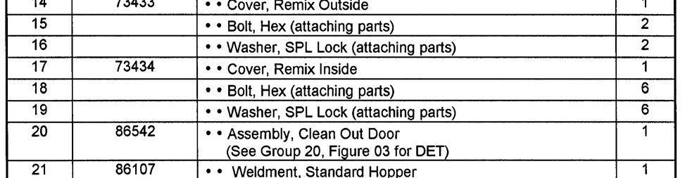
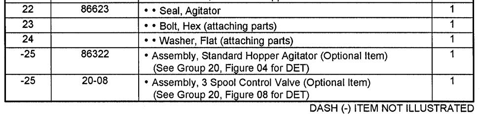
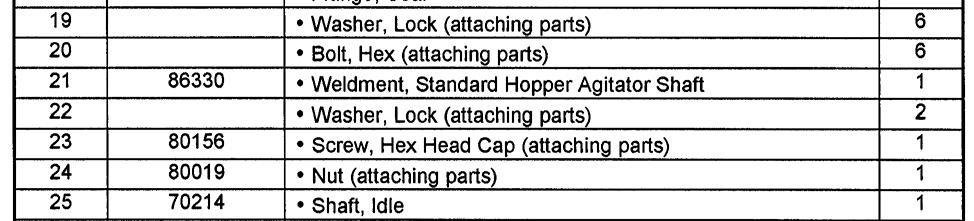
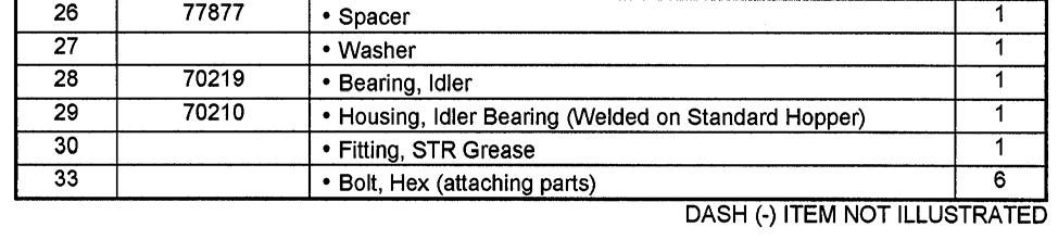
31 HOPPER CLEAN OUT DOOR ASSEMBLY (ROUNDED) GROUP 20 FIGURE 03 PAGE 02 ITEM NO. REED S NO. DESCRIPTION Assembly, Rounded Clean Out Door (See Group 20, Figure 01 and Figure 02 for NHA ) Bolt, Shoulder OPEN Door, Weldment Clean-Out 1 5 W A Cord, Hopper Door O-Ring 2.21 FT OPEN Block, RH Clean Out Door Block, LH Clean Out Door 1 9 Capscrew, Socket Head Plate, Seal Neck, Clean Out Door 1 QTY Ref
32 STANDARD HOPPER AGITATOR ASSEMBLY GROUP 20 FIGURE 04 PAGE 01


33 STANDARD HOPPER AGITATOR ASSEMBLY GROUP 20 FIGURE 04 PAGE 02
34 STANDARD HOPPER AGITATOR MOTOR ASSEMBLY GROUP 20 FIGURE 05 PAGE 01


35 STANDARD HOPPER AGITATOR MOTOR ASSEMBLY GROUP 20 FIGURE 05 PAGE 02
36 3 SPOOL CONTROL VALVE ASSEMBLY GROUP 20 FIGURE 06 PAGE 01

37 3 SPOOL CONTROL VALVE ASSEMBLY GROUP 20 FIGURE 06 PAGE 02
38 3 SPOOL CONTROL VALVE SUB-ASSEMBLY GROUP 20 FIGURE 07 PAGE 01
39 3 SPOOL CONTROL SUB-ASSEMBLY GROUP 20 FIGURE 07 PAGE 02
40 TRAILER MOUNTED PUMP MODEL ILLUSTRATED MANUAL GROUP 20 FIGURE 08 PAGE 01 THIS PAGE INTENTIONALLY LEFT BLANK.
41 TRAILER MOUNTED PUMP MODEL GROUP 30 TANK INSTALLATION GROUP 30 FIGURE 00 PAGE 01 REED TRAILER MOUNTED CONCRETE PUMP 05 MODEL ILLUSTRATED MANUAL GROUP 30 HYDRAULIC TANK INSTALLATION CONTAINS THE FOLLOWING FIGURES: FIGURE 00 FIGURE 01 FIGURE 02 FIGURE 03 FIGURE 04 FIGURE 05 FIGURE 06 FIGURE 07 FIGURE 08 FIGURE 09 FIGURE 10 FIGURE 11 TABLE OF CONTENTS TANK INSTALLATION HYDRAULIC TANK ASSEMBLY SWING TUBE CIRCUIT MANIFOLD ASSEMBLY SWING TUBE CIRCUIT MAIN SOLENOID VALVE ASSEMBLY SWING TUBE CIRCUIT PILOT SOLENOID VALVE ASSEMBLY BALL VALVE ASSEMBLY DRIVE CYLINDER CIRCUIT MANIFOLD ASSEMBLY DRIVE CYLINDER CIRCUIT MAIN SOLENOID VALVE ASSEMBLY DRIVE CYLINDER CIRCUIT PILOT SOLENOID VALVE ASSEMBLY ACCUMULATOR ASSEMBLY ACCUMULATOR BLADDER REPAIR KIT
42 TANK INSTALLATION GROUP 30 FIGURE 01 PAGE 01
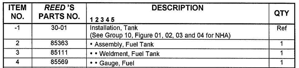
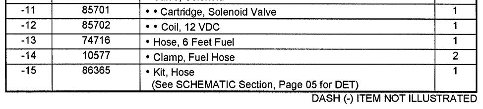
43 TANK INSTALLATION GROUP 30 FIGURE 01 PAGE 02
44 HYDRAULIC TANK ASSEMBLY GROUP 30 FIGURE 02 PAGE 01


45 HYDRAULIC TANK ASSEMBLY GROUP 30 FIGURE 02 PAGE 02
46 SWING TUBE CIRCUIT MANIFOLD ASSEMBLY GROUP 30 FIGURE 03 PAGE 01


47 SWING TUBE CIRCUIT MANIFOLD ASSEMBLY GROUP 30 FIGURE 03 PAGE 02
48 SWING TUBE CIRCUIT MAIN SOLENOID VALVE ASSEMBLY GROUP 30 FIGURE 04 PAGE 01
49 SWING TUBE CIRCUIT MAIN SOLENOID VALVE ASSEMBLY GROUP 30 FIGURE 04 PAGE 02
50 SWING TUBE CIRCUIT PILOT SOLENOID VALVE ASSEMBLY GROUP 30 FIGURE 05 PAGE 01

51 SWING TUBE CIRCUIT PILOT SOLENOID VALVE ASSEMBLY GROUP 30 FIGURE 05 PAGE 02

52 BALL VALVE ASSEMBLY GROUP 30 FIGURE 06 PAGE 01
53 BALL VALVE ASSEMBLY GROUP 30 FIGURE 06 PAGE 02
54 DRIVE CYLINDER CIRCUIT MANIFOLD ASSEMBLY GROUP 30 FIGURE 07 PAGE 01


55 DRIVE CYLINDER CIRCUIT MANIFOLD ASSEMBLY GROUP 30 FIGURE 07 PAGE 02
56 DRIVE CYLINDER CIRCUIT MAIN SOLENOID VALVE ASSEMBLY GROUP 30 FIGURE 08 PAGE 01

57 DRIVE CYLINDER CIRCUIT MAIN SOLENOID VALVE ASSEMBLY GROUP 30 FIGURE 08 PAGE 02
58 DRIVE CYLINDER CIRCUIT PILOT SOLENOID VALVE ASSEMBLY GROUP 30 FIGURE 09 PAGE 01

59 SWING TUBE CIRCUIT PILOT SOLENOID VALVE ASSEMBLY GROUP 30 FIGURE 09 PAGE 02
60 ACCUMULATOR ASSEMBLY GROUP 30 FIGURE 10 PAGE 01

61 ACCUMULATOR ASSEMBLY GROUP 30 FIGURE 10 PAGE 02
62 ACCUMULATOR BLADDER REPAIR KIT GROUP 30 FIGURE 11 PAGE 01

63 ACCUMULATOR BLADDER REPAIR KIT GROUP 30 FIGURE 11 PAGE 02
64 TRAILER MOUNTED PUMP MODEL ILLUSTRATED MANUAL GROUP 30 FIGURE 12 PAGE 01 THIS PAGE INTENTIONALLY LEFT BLANK.


65 TRAILER MOUNTED PUMP MODEL GROUP 40 POWER TRAIN INSTALLATION GROUP 40 FIGURE 00 PAGE 01 REED TRAILER MOUNTED CONCRETE PUMP 05 MODEL ILLUSTRATED MANUAL GROUP 40 POWER TRAIN INSTALLATION CONTAINS THE FOLLOWING FIGURES: FIGURE 00 FIGURE 01 FIGURE 02 FIGURE 03 FIGURE 04 FIGURE 05 FIGURE 06 TABLE OF CONTENTS POWER TRAIN INSTALLATION HYDRAULIC PUMPS ASSEMBLY SINGLE AUXILIARY PUMP ASSEMBLY DOUBLE AUXILIARY PUMP ASSEMBLY MAIN PUMP ASSEMBLY BATTERY MOUNTING ASSEMBLY
66 POWER TRAIN INSTALLATION GROUP 40 FIGURE 01 PAGE 01
67 POWER TRAIN INSTALLATION GROUP 40 FIGURE 01 PAGE 02 ITEM NO. REED S NO. DESCRIPTION Installation, Power Train Ref (See Group 10, Figure 01, 02, 03 and 04 for NHA) Assembly, Main and Auxiliary Pumps 1 (See Group 40, Figure 02 for DET) Clamp, T-Bolt-3.00 Dia Stem, 2 1/2 90 Deg-40GL-40FL Split Flange-Code SAE Split Flange-Code SAE Flange, FLH6K-MJ Band, Mounting-8.50 Dia Clamp, Torctite-3.00 Dia Cap, Rain-3.00 Dia Elbow, Exhaust-3.00 Dia Exhaust Flex Tube-3.00 Dia x 12 Long Muffler, B-Series Cummins Clamp, Exhaust-Bent Bolt-3.00 Dia Clamp, Exhaust-3.00 Dia Assembly, Engine (4-Cylinder Diesel Engine) (See Vendor Section, Figure 01 for REF) Mount, Fuel Filter Tube, Hydraulic Cylinders Tube, Hydraulic-Shift Cylinders Tube, Hydraulic-Shift Cylinder Hose Kit-/B70 Kawasaki/Cummins Minicheck Hose Clamp, Tube-Single-1 1/ Clamp, Tube-Dual 5/ Strap, Ground Relay, Starter Gauge, Prox. Sensor Setting Wiring Harness-Engine Assembly, Battery Mounting (See Figure 05 for DET) 1 DASH (-) ITEM NOT ILLUSTRATED QTY
68 POWER TRAIN INSTALLATION GROUP 40 FIGURE 01 PAGE 03
69 POWER TRAIN INSTALLATION GROUP 40 FIGURE 01 PAGE 04 ITEM NO. REED S NO. DESCRIPTION Installation, Power Train Ref (See Group 10, Figure 01, 02, 03 and 04 for NHA) Assembly, Main and Auxiliary Pumps 1 (See Group 40, Figure 02 for DET) Clamp, T-Bolt-3.00 Dia Stem, 2 1/2 90 Deg-40GL-40FL Split Flange-Code SAE Split Flange-Code SAE Flange, FLH6K-MJ Band, Mounting-8.50 Dia Clamp, Torctite-3.00 Dia Cap, Rain-3.00 Dia Elbow, Exhaust-3.00 Dia Exhaust Flex Tube-3.00 Dia x 12 Long Muffler, B-Series Cummins Clamp, Exhaust-Bent Bolt-3.00 Dia Clamp, Exhaust-3.00 Dia Assembly, Engine (4-Cylinder Diesel Engine) (See Vendor Section, Figure 01 for REF) Mount, Fuel Filter Tube, Hydraulic Cylinders Tube, Hydraulic-Shift Cylinders Tube, Hydraulic-Shift Cylinder Hose Kit-/B70 Kawasaki/Cummins Minicheck Hose Clamp, Tube-Single-1 1/ Clamp, Tube-Dual 5/ Strap, Ground Relay, Starter Gauge, Prox. Sensor Setting Wiring Harness-Engine Assembly, Battery Mounting (See Figure 05 for DET) 1 DASH (-) ITEM NOT ILLUSTRATED QTY
70 HYDRAULIC PUMPS ASSEMBLY GROUP 40 FIGURE 02 PAGE 01
71 HYDRAULIC PUMPS ASSEMBLY GROUP 40 FIGURE 02 PAGE 02 ITEM NO. REED S NO. DESCRIPTION Assembly, Hydraulic Pump (See Group 40, Figure 01 for NHA) 2 Washer, Lock 2 3 Bolt, Hex Fitting, 90 MB-MJ Assembly, Double Auxiliary Pump (See Group 40, Figure 04 for DET) Fitting, Adaptor MB-MJ Stem ML Stem ML NPN Fitting, Elbow MB-MJ Fitting, Elbow MB-MJ NPN Fitting, Elbow MB-MJ Kit, Split Flange-Code SAE Assembly, Main Pump (See Group 40, Figure 05 for DET) (Also See Vendor Section, Figure 02 for REF) 1 14 Washer, Lock (attaching parts) 4 15 Bolt, Hex (attaching parts) Kit, Split Flange-Code SAE Assembly, Flywheel Coupling (Pump Drive) 1 18 Bolt, Hex Washer, SPL Plate, Flywheel 1 21 Screw 6 22 Washer 6 23 Plate, Flywheel 1 DASH (-) ITEM NOT ILLUSTRATED QTY Ref
72 DOUBLE AUXILIARY PUMP ASSEMBLY GROUP 40 FIGURE 03 PAGE 01
73 DOUBLE AUXILIARY PUMP ASSEMBLY GROUP 40 FIGURE 03 PAGE 02 ITEM NO. REED S NO. DESCRIPTION Assembly Double Auxiliary Pump (See Group 40, Figure 02 for NHA) 1 Cover, Front 1 2 Cover, Twin Rear 1 3 Plate, Thrust 1 4 Plate, Thrust 1 5 Plate, Thrust 1 6 Plate, Thrust 1 7 Gear, Drive 1 8 Gear, Driven 1 9 Shaft, Drive 1 10 Gear, Driven 1 11 Screw 4 12 Washer 4 13 O-Ring 1 14 Seal 2 15 Seal 2 16 Plate, Seal 1 17 Seal, Shaft 1 18 Ring 1 19 Plate, Anti-Intrusion 2 20 Ring, Back-Up 2 21 Hub 1 22 Pin, Dowel 2 23 Body 1 DASH (-) ITEM NOT ILLUSTRATED QTY Ref
74 KAWASAKI MODEL K3VL MAIN PUMP ASSEMBLY GROUP 40 FIGURE 04 PAGE 01
75 KAWASAKI MODEL K3VL MAIN PUMP ASSEMBLY GROUP 40 FIGURE 04 PAGE 02
76 BATTERY MOUNT ASSEMBLY GROUP 40 FIGURE 05 PAGE 01


77 BATTERY MOUNT ASSEMBLY GROUP 40 FIGURE 05 PAGE 02
78 TRAILER MOUNTED PUMP MODEL ILLUSTRATED MANUAL GROUP 40 FIGURE 06 PAGE 01 THIS PAGE INTENTIONALLY LEFT BLANK.
79 TRAILER MOUNTED PUMP MODEL GROUP 50 CONTROLS INSTALLATION GROUP 50 FIGURE 00 PAGE 01 REED TRAILER MOUNTED CONCRETE PUMP 05 MODEL ILLUSTRATED MANUAL GROUP 50 CONTROLS INSTALLATION CONTAINS THE FOLLOWING FIGURES: FIGURE 00 FIGURE 01 FIGURE 02 FIGURE 03 FIGURE 04 FIGURE 05 TABLE OF CONTENTS CONTROLS INSTALLATION CONTROL BOX ASSEMBLY 50 FEET CABLE REMOTE CONTROL ASSEMBLY 100 FEET CABLE REMOTE CONTROL ASSEMBLY RADIO REMOTE CONTROL ASSEMBLY
80 CONTROL INSTALLATION GROUP 50 FIGURE 01 PAGE 01
81 CONTROL INSTALLATION GROUP 50 FIGURE 01 PAGE 02 ITEM NO. REED S NO. DESCRIPTION Installation, Control Ref (See Group 10, Figure 01, 02, 03 and 04 for NHA) Gauge, 3,000 PSI Hydraulic 1 (See Group 30, Figure 02 for REF) Gauge, 6,000 PSI Hydraulic 1 (See Group 30, Figure 02 for REF) Cartridge, Flow Control Valve 1 (See Group 30, Figure 07 for REF) Horn, 12 V Assembly, Control Box (See Group 50, Figure 02 for DET) Assembly, 50 Feet Cable Remote Control (See Group 50, Figure 03 for DET) 8 NPN Assembly, 100 Feet Cable Remote Control (See Group 50, Figure 04 for DET) Assembly, Radio Remote Control (Optional Item) (See Group 50, Figure 05 for DET) Assembly, 3 Spool Control Valve (Optional Item) (See Group 20, Figure 08 for REF) Assembly, 1 Spool Control Valve (Optional Item) (See Group 80, Figure 16 for REF) Assembly, 2 Spool Control Valve (Optional Item) (See Group 80, Figure 18 for REF) DASH (-) ITEM NOT ILLUSTRATED QTY
82 CONTROL BOX ASSEMBLY GROUP 50 FIGURE 02 PAGE 01
83 CONTROL BOX ASSEMBLY GROUP 50 FIGURE 02 PAGE 02 ITEM NO. REED S NO. DESCRIPTION Assembly, Control Box (See Group 50, Figure 01 for NHA) Fuse, 25A Fuse, 10A Fuse, 15A Fuse, 20A QTY Ref
84 50 FEET CABLE REMOTE CONTROL ASSEMBLY GROUP 50 FIGURE 03 PAGE 01
85 50 FEET CABLE REMOTE CONTROL ASSEMBLY GROUP 50 FIGURE 03 PAGE 02
86 100 FEET CABLE REMOTE CONTROL ASSEMBLY GROUP 50 FIGURE 04 PAGE 01
87 100 FEET CABLE REMOTE CONTROL ASSEMBLY GROUP 50 FIGURE 04 PAGE 02

88 OPTIONAL RADIO REMOTE CONTROL ASSEMBLY GROUP 50 FIGURE 05 PAGE 01
89 OPTIONAL RADIO REMOTE CONTROL ASSEMBLY GROUP 50 FIGURE 05 PAGE 02
90 TRAILER MOUNTED PUMP MODEL ILLUSTRATED MANUAL GROUP 50 FIGURE 06 PAGE 01 THIS PAGE INTENTIONALLY LEFT BLANK.
91 TRAILER MOUNTED PUMP MODEL GROUP 60 PUMPING TRAIN INSTALLATION GROUP 60 FIGURE 00 PAGE 01 REED TRAILER MOUNTED CONCRETE PUMP 05 MODEL ILLUSTRATED MANUAL GROUP 60 PUMPING TRAIN INSTALLATION CONTAINS THE FOLLOWING FIGURES: FIGURE 00 FIGURE 01 FIGURE 02 FIGURE 03 FIGURE 04 FIGURE 05 FIGURE 06 FIGURE 07 FIGURE 08 FIGURE 09 FIGURE 10 TABLE OF CONTENTS SINGLE SHIFT PUMPING TRAIN INSTALLATION DUAL SHIFT PUMPING TRAIN INSTALLATION SINGLE SHIFT SWING VALVE ASSEMBLY DUAL SHIFT SWING VALVE ASSEMBLY SINGLE SHIFT SWING RAM CYLINDER SUB-ASSEMBLY DUAL SHIFT SWING RAM CYLINDER SUB-ASSEMBLY MATERIAL CYLINDER ASSEMBLY FLUSHBOX ASSEMBLY HYDRAULIC DRIVE CYLINDER ASSEMBLY HYDRAULIC DRIVE CYLINDER SUB-ASSEMBLY
92 SINGLE SHIFT PUMPING TRAIN INSTALLATION GROUP 60 FIGURE 01 PAGE 01
93 SINGLE SHIFT PUMPING TRAIN INSTALLATION GROUP 60 FIGURE 01 PAGE 02 ITEM NO. REED S NO. DESCRIPTION Installation, Single Shift Pumping Train (See Group 10, Figure 01 and Figure 03 for NHA) Assembly, Single Shift Swing Valve (See Group 60, Figure 02 for DET) Installation, Standard Hopper (See Group 20, Figure 01 for REF) Installation, Harsh Mix Hopper (See Group 20, Figure 02 for REF) Assembly, Material Cylinder (See Group 60, Figure 07 for DET) Assembly, Flushbox (See Group 60, Figure 08 for DET) Assembly, Hydraulic Drive Cylinder (See Group 60, Figure 06 for DET) DASH (-) ITEM NOT ILLUSTRATED QTY Ref 1 Ref Ref 1 1 1
94 DUAL SHIFT PUMPING TRAIN INSTALLATION GROUP 60 FIGURE 02 PAGE 01
95 DUAL SHIFT PUMPING TRAIN INSTALLATION GROUP 60 FIGURE 02 PAGE 02 ITEM NO. REED S NO. DESCRIPTION Installation, Dual Shift Pumping Train (See Group 10, Figure 01 and Figure 03 for NHA) Assembly, Dual Shift Swing Valve (See Group 60, Figure 02 for DET) Installation, Standard Hopper (See Group 20, Figure 01 for REF) Installation, Harsh Mix Hopper (See Group 20, Figure 02 for REF) Assembly, Material Cylinder (See Group 60, Figure 07 for DET) Assembly, Flushbox (See Group 60, Figure 08 for DET) Assembly, Hydraulic Drive Cylinder (See Group 60, Figure 06 for DET) DASH (-) ITEM NOT ILLUSTRATED QTY Ref 1 Ref Ref 1 1 1
96 SINGLE SHIFT SWING VALVE ASSEMBLY GROUP 60 FIGURE 03 PAGE 01
97 SINGLE SHIFT SWING VALVE ASSEMBLY GROUP 60 FIGURE 03 PAGE 02 05/20/04
98 SINGLE SHIFT SWING VALVE ASSEMBLY GROUP 60 FIGURE 03 PAGE 03


99 SINGLE SHIFT SWING VALVE ASSEMBLY GROUP 60 FIGURE 03 PAGE 04
100 DUAL SHIFT SWING VALVE ASSEMBLY GROUP 60 FIGURE 04 PAGE 01
101 DUAL SHIFT SWING VALVE ASSEMBLY GROUP 60 FIGURE 04 PAGE 02 05/20/04
102 DUAL SHIFT SWING VALVE ASSEMBLY GROUP 60 FIGURE 04 PAGE 03


103 DUAL SHIFT SWING VALVE ASSEMBLY GROUP 60 FIGURE 04 PAGE 04
104 SINGLE SHIFT SWING RAM CYLINDER ASSEMBLY GROUP 60 FIGURE 05 PAGE 01

105 SINGLE SHIFT SWING RAM CYLINDER ASSEMBLY GROUP 60 FIGURE 05 PAGE 02
106 DUAL SHIFT SWING RAM CYLINDER ASSEMBLY GROUP 60 FIGURE 06 PAGE 01

107 DUAL SHIFT SWING RAM CYLINDER ASSEMBLY GROUP 60 FIGURE 06 PAGE 02
108 MATERIAL CYLINDER ASSEMBLY GROUP 60 FIGURE 07 PAGE 01


109 MATERIAL CYLINDER ASSEMBLY GROUP 60 FIGURE 07 PAGE 02
110 FLUSH BOX ASSEMBLY GROUP 60 FIGURE 08 PAGE 01


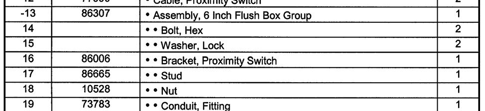
111 FLUSH BOX ASSEMBLY GROUP 60 FIGURE 08 PAGE 02
112 HYDRAULIC DRIVE CYLINDER ASSEMBLY GROUP 60 FIGURE 09 PAGE 01
113 HYDRAULIC DRIVE CYLINDER ASSEMBLY GROUP 60 FIGURE 09 PAGE 02 ITEM NO. REED S NO. DESCRIPTION Assembly, Hydraulic Drive Cylinder Ref (See Group 60, Figure 01 and Figure 02 for NHA) Assembly, Drive Cylinder 1 (See Group 60, Figure 10 for DET) 3 Nut, Hex (attaching parts) 8 4 Washer, Lock (attaching parts) Washer, Thread (attaching parts) 8 6 Bolt (attaching parts) 8 7 Fitting, Fitting, Fitting, Valve, Check Assembly, Tube Plate, End 1 13 Washer, Flat (attaching parts) 4 14 Washer, Lock (attaching parts) 4 15 Bolt, Hex (attaching parts) 4 QTY
114 DRIVE CYLINDER ASSEMBLY GROUP 60 FIGURE 10 PAGE 01
115 DRIVE CYLINDER ASSEMBLY GROUP 60 FIGURE 10 PAGE 02 ITEM NO. REED S NO. DESCRIPTION Assembly, Drive Cylinder Ref (See Group 60, Figure 09 for NHA) 2 Ring, Threaded 1 3 Gland, Head 1 4 Rod, Cylinder 1 5 Piston 1 6 Nut, Piston 1 7 Plug 4 8 Weldment, Cylinder Case SK Kit, Seal 1 10 Wiper, Rod 1 11 Plug, Nylon 1 12 Ring, Back Up 1 13 U-Cup 1 14 Seal, Buffer 1 15 O-Ring 2 16 Ring, Back Up 2 17 O-Ring 1 18 Seal, Piston 2 19 Ring, Wear 1 QTY
116 TRAILER MOUNTED PUMP MODEL ILLUSTRATED MANUAL GROUP 60 FIGURE 11 PAGE 01 THIS PAGE INTENTIONALLY LEFT BLANK.


117 TRAILER MOUNTED PUMP MODEL GROUP 70 FRAME INSTALLATION GROUP 70 FIGURE 00 PAGE 01 REED TRAILER MOUNTED CONCRETE PUMP 05 MODEL ILLUSTRATED MANUAL GROUP 70 FRAME INSTALLATION CONTAINS THE FOLLOWING FIGURES: FIGURE 00 FIGURE 01 FIGURE 02 FIGURE 03 FIGURE 04 TABLE OF CONTENTS FRAME INSTALLATION HUB AND BRAKE ASSEMBLY NON-OPERATOR SIDE ELECTRIC BRAKE ASSEMBLY OPERATOR SIDE ELECTRIC BRAKE ASSEMBLY
118 FRAME INSTALLATION GROUP 70 FIGURE 01 PAGE 01
119 FRAME INSTALLATION GROUP 70 FIGURE 01 PAGE 02 ITEM REED S DESCRIPTION NO. NO. QTY Installation, Frame Ref (See Group 10, Figure 01 for NHA) Weldment, Outrigger Inner Weldment, Outrigger Outer Tube Pin, Outrigger Safety Lanyard, Q/R Pin Light, Tail Weldment, Right Fender Weldment, Left Fender Panel, Top Cover, Control Box 1 11A Cover, Front 1 11B Gusset Cover, Tool Box Assembly, Trailer Wiring Harness 1 (See Schematic Section, Page 12 for REF) Kit, Break Away 1 15A Chain Assembly 2 15B Shackle Anchor Chain, 3/8 Proof Coil GR FT Assembly, Frame Drawbar Weldment, Jack Weldment, Frame Axle-9000 lbs Assembly, Hub and Brake 1 (See Group 70, Figure 02 for DET) Assembly, Wheel and Tire Bumper 4 DASH (-) ITEM NOT ILLUSTRATED

120 HUB AND BRAKE ASSEMBLY GROUP 70 FIGURE 02 PAGE 01
121 HUB AND BRAKE ASSEMBLY GROUP 70 FIGURE 02 PAGE 02 ITEM NO. REED S NO. DESCRIPTION A Assembly, Hub and Brake (Left and Right Side) (See Group 70, Figure 01 for NHA) 1 Seal, Oil 1 2 Cone, Inner Bearing 1 3 Cup, Inner Bearing 1 4 Cup, Outer Bearing 1 5 Cone, Outer Bearing 1 6 Nut, Spindle 2 7 Washer, Spindle 1 8 Washer, Tang 1 9* Cap, Oil 1 10* O -Ring 1 11 LH/RH Electric Brake Set -12 1/4 x 3 3/8 Ref 12* Plug, Oil Cap 1 13 Stud, Wheel 5/ Screw, Drum Mounting 2 15 Bolt, Brake Mounting 2 16 Nut, Brake Mounting 2 17 Wheel, Steel x 6.75 (8 on 6.5 BC) Ref 18 Nut, Cone 5/ Ring, Clamp 1 20 Drum, Brake 1 21 Hub, Oil W/Cups and Studs Oil Cap Kit-(* includes Items 9,10 & 12) 1 QTY Ref DASH (-) ITEM NOT ILLUSTRATED
122 NON OPERATOR SIDE ELECTRIC BRAKE ASSEMBLY GROUP 70 FIGURE 03 PAGE 01
123 NON OPERATOR SIDE ELECTRIC BRAKE ASSEMBLY GROUP 70 FIGURE 03 PAGE 02 ITEM NO. REED S NO. DESCRIPTION A LH Assembly, Non-Operator Side Electric Brake (Left Side) Ref (See Group 70, Figure 02 for NHA) 1 LH Shoe & Lining Kit 1 2 Backing Plate Assembly 1 3 Brake Mounting Nut 4 4 Lockwasher 4 5 LH Actuating Arm Assembly 1 6 Wire Clip 3 7 LH Arm/Shoe Retainer 1 8 Flange Nut 1 9 Magnet Kit 1 10 Centering Spring 2 11 Adjuster Cable 1 12 LH Adjuster Lever 1 13 Return Spring 1 14 Adjuster Spring 1 15 LH Adjuster Assembly (Silver) 1 16 Dust Shield 1 17 Brake Mounting Bolt 4 18 Adjuster Clip (Thread End) 1 19 Wire Grommet 1 20 Adjuster Clip (Barrel End) DASH (-) ITEM NOT ILLUSTRATED - QTY
124 OPERATOR SIDE ELECTRIC BRAKE ASSEMBLY GROUP 70 FIGURE 04 PAGE 01
125 OPERATOR SIDE ELECTRIC BRAKE ASSEMBLY GROUP 70 FIGURE 04 PAGE 02 ITEM NO. REED S NO. DESCRIPTION A RH Assembly, Operator Side Electric Brake (Right Side) Ref (See Group 70, Figure 02 for NHA) 1 RH Shoe & Lining Kit 1 2 Backing Plate Assembly 1 3 Brake Mounting Nut 4 4 Lockwasher 4 5 RH Actuating Arm Assembly 1 6 Wire Clip 3 7 RH Arm/Shoe Retainer 1 8 Flange Nut 1 9 Magnet Kit 1 10 Centering Spring 2 11 Adjuster Cable 1 12 RH Adjuster Lever 1 13 Return Spring 1 14 Adjuster Spring 1 15 RH Adjuster Assembly (Gold) 1 16 Dust Shield 1 17 Brake Mounting Bolt 4 18 Adjuster Clip (Thread End) 1 19 Wire Grommet 1 20 Adjuster Clip (Barrel End) DASH (-) ITEM NOT ILLUSTRATED - QTY
126 TRAILER MOUNTED PUMP MODEL ILLUSTRATED MANUAL GROUP 70 FIGURE 05 PAGE 01 THIS PAGE INTENTIONALLY LEFT BLANK.
127 TRAILER MOUNTED PUMP MODEL GROUP 80 OPTIONAL INSTALLATION GROUP 80 FIGURE 00 PAGE 01 REED TRAILER MOUNTED CONCRETE PUMP 05 MODEL ILLUSTRATED MANUAL GROUP 80 OPTIONAL INSTALLATION CONTAINS THE FOLLOWING FIGURES: FIGURE 00 FIGURE 01 FIGURE 02 FIGURE 03 FIGURE 04 FIGURE 05 FIGURE 06 FIGURE 07 FIGURE 08 FIGURE 09 FIGURE 10 FIGURE 11 FIGURE 12 FIGURE 13 FIGURE 14 FIGURE 15 FIGURE 16 FIGURE 17 FIGURE 18 FIGURE 19 FIGURE 20 FIGURE 21 TABLE OF CONTENTS OPTIONAL INSTALLATION CENTRALIZED LUBE BLOCK ASSEMBLY AUTOLUBE 12 VOLT LUBE PUMP ASSEMBLY 12 VOLT LUBE PUMP ASSEMBLY HOPPER VIBRATOR ASSEMBLY ACCUMULATOR CHARGE KIT OPTIONAL TOOL KIT ASSEMBLY SURGE BRAKES ASSEMBLY-PINTLE HITCH WATER PUMP INSTALLATION WATER PUMP CONTROL VALVE ASSEMBLY WATER PUMP MOTOR ASSEMBLY WATER PUMP ASSEMBLY NON-OPERATOR SIDE HYDRAULIC BRAKE ASSEMBLY OPERATOR SIDE HYDRAULIC BRAKE ASSEMBLY HYDRAULIC OUTRIGGER CYLINDER ASSEMBLY 1 SPOOL CONTROL VALVE ASSEMBLY 1 SPOOL CONTROL VALVE SUB-ASSEMBLY 2 SPOOL CONTROL VALVE ASSEMBLY 2 SPOOL CONTROL VALVE SUB-ASSEMBLY TIRE & WHEEL ASSEMBLY - ALUMINUM 50 FEET STROKE COUNTER REMOTE CONTROLLER
128 OPTIONAL INSTALLATION GROUP 80 FIGURE 01 PAGE 01
129 OPTIONAL INSTALLATION GROUP 80 FIGURE 01 PAGE 02
130 CENTRALIZED LUBE BLOCK ASSEMBLY GROUP 80 FIGURE 02 PAGE 01
131 CENTRALIZED LUBE BLOCK ASSEMBLY GROUP 80 FIGURE 02 PAGE 02 ITEM REED S DESCRIPTION NO. NO QTY A Assembly, Centralized Lube Block (See Group 80, Figure 01 for NHA) Ref Block, Union-Lincoln Lube Hose Coupling Fitting, Hose 8-4 Fitting, Lube 45-1/8 NPT 4-5 Hose, Plastic-1/4 O.D. Tubing A/R -6 Hose, Plastic-5/16 O.D. Tubing A/R DASH (-) ITEM NOT ILLUSTRATED
132 AUTOLUBE 12 VOLT PUMP ASSEMBLY (PLASTIC TUBING) GROUP 80 FIGURE 03 PAGE 01
133 AUTOLUBE 12 VOLT PUMP ASSEMBLY (PLASTIC TUBING) GROUP 80 FIGURE 03 PAGE 02 ITEM REED S DESCRIPTION NO. NO QTY A Assembly, AUTOLUBE 12 Volt-Plastic Tubing (See Group 80, Figure 01 for NHA) Ref Lube Pump Assy-12V (Plastic Tubing) Block, Union-Lincoln Lube Hose Coupling Fitting, Hose Guard Bracket, Lube Block Mount 1 7 Block, Divider Valve-18 Outlets 1 8 Valve, Pressure Relief 1 9 Hose, Plastic-1/4 O.D. A/R 10 Hose, Plastic-5/16 O.D. A/R DASH (-) ITEM NOT ILLUSTRATED
134 AUTOLUBE 12 VOLT LUBE ASSEMBLY (STEEL TUBING) GROUP 80 FIGURE 03 PAGE 03
135 AUTOLUBE 12 VOLT LUBE ASSEMBLY (STEEL TUBING) GROUP 80 FIGURE 03 PAGE 04 ITEM REED S DESCRIPTION NO. NO QTY A Assembly, AUTOLUBE 12 Volt-Steel Tubing (See Group 80, Figure 01 for NHA) Ref Lube Pump Assy-12V (Steel Tubing) Block, Union-Lincoln Lube Hose Coupling Fitting, Hose Guard Bracket, Lube Block Mount 1 7 Block, Divider Valve-18 Outlets 1 8 Valve, Pressure Relief 1 9 Tubing, Steel-1/4 O.D. A/R 10 Hose, Plastic-1/4 O.D. A/R 11 Hose, Plastic-5/16 O.D. A/R DASH (-) ITEM NOT ILLUSTRATED

136 12 VOLT LUBE PUMP ASSEMBLY GROUP 80 FIGURE 04 PAGE 01


137 12 VOLT LUBE PUMP ASSEMBLY GROUP 80 FIGURE 04 PAGE 02
138 HOPPER VIBRATOR ASSEMBLY GROUP 80 FIGURE 05 PAGE 03

139 HOPPER VIBRATOR ASSEMBLY GROUP 80 FIGURE 05 PAGE 04
140 ACCUMULATOR CHARGE KIT GROUP 80 FIGURE 06 PAGE 01


141 ACCUMULATOR CHARGE KIT GROUP 80 FIGURE 06 PAGE 02


142 OPTIONAL TOOL KIT ASSEMBLY GROUP 80 FIGURE 07 PAGE 01


143 OPTIONAL TOOL KIT ASSEMBLY GROUP 80 FIGURE 07 PAGE 02
144 SURGE BRAKES ASSEMBLY WITH PINTLE HITCH-3 EYE GROUP 80 FIGURE 08 PAGE 01
145 SURGE BRAKES ASSEMBLY WITH PINTLE HITCH-3 EYE GROUP 80 FIGURE 08 PAGE 02 ITEM REED S DESCRIPTION NO. NO QTY Assembly, Surge Brakes-B20 Pintle Hitch (3 Eye) (See Group 80, Figure 01 for NHA) Ref 2 Case, Outer 1 3 Spring, Breakaway 1 4 Lever, Breakaway Pin 1 5 S-Hook 1 6 Roller, Front 1 7 Cover, Front Roller 1 8 Pin, Front Roller 1 9 Washer, Front Roller Pin 1 10 Pin, Cotter 1 11 Bearing 2 12 Lunette Eye, Inner Side 1 13 Pin, Master 1 14 Roller, Rear 2 15 Washer, Master Pin 1 16 Pin, Cotter 1 17 Pin, Damper 1 18 Damper 1 19 Pin, Cotter 1 20 Bolt, Hex 2 21 Rod, Push 1 22 Plate, Cylinder Mounting 1 23 Bolt, Self Topping 4 24 Cylinder, Master 1 25 Connector, Orifice 1 26 Cap, Master Cylinder with Gasket 1 27 Spring 2 28 Washer 2 29 Nut, hex Actuator, Surge Brake-6000 LBS Eye-Lunette Hydraulic Brake Kit-12 X Torsion Spring-Brake Kit Bracket, Surge Brake Actuator Mounting 1 DASH (-) ITEM NOT ILLUSTRATED


146 WATER PUMP INSTALLATION GROUP 80 FIGURE 09 PAGE 01

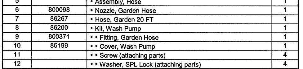
147 WATER PUMP INSTALLATION GROUP 80 FIGURE 09 PAGE 02
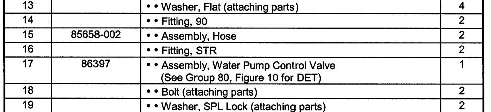
148 WATER PUMP CONTROL VALVE ASSEMBLY GROUP 80 FIGURE 10 PAGE 01
149 WATER PUMP CONTROL VALVE ASSEMBLY GROUP 80 FIGURE 10 PAGE 02
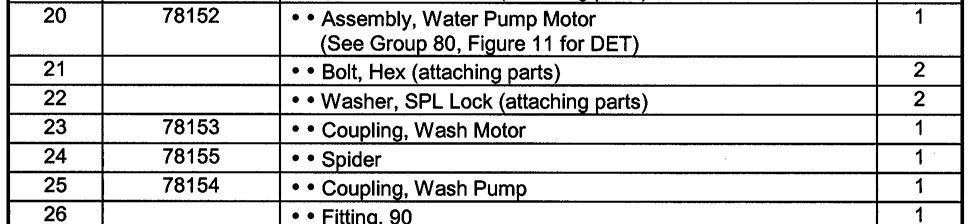
150 WATER PUMP MOTOR ASSEMBLY GROUP 80 FIGURE 11 PAGE 01
151 WATER PUMP MOTOR ASSEMBLY GROUP 80 FIGURE 11 PAGE 02
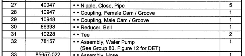
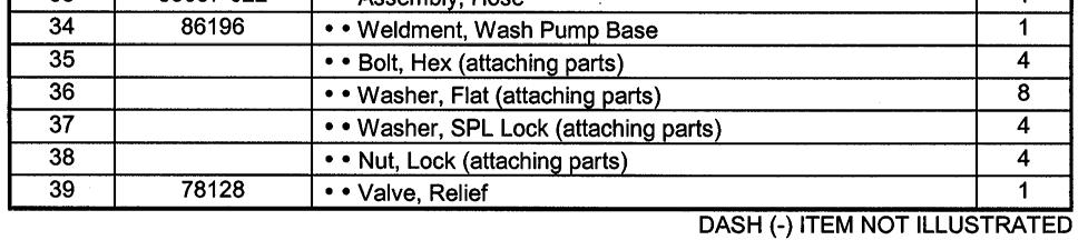
152 WATER PUMP ASSEMBLY GROUP 80 FIGURE 12 PAGE 01


153 WATER PUMP ASSEMBLY GROUP 80 FIGURE 12 PAGE 02
154 NON-OPERATOR SIDE HYDRAULIC BRAKE ASSEMBLY GROUP 80 FIGURE 13 PAGE 01
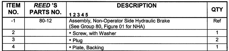
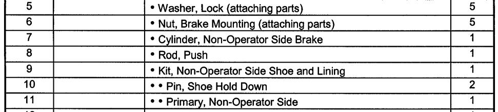
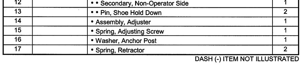
155 NON-OPERATOR SIDE HYDRAULIC BRAKE ASSEMBLY GROUP 80 FIGURE 13 PAGE 02
156 OPERATOR SIDE HYDRAULIC BRAKE ASSEMBLY GROUP 80 FIGURE 14 PAGE 01


157 OPERATOR SIDE HYDRAULIC BRAKE ASSEMBLY GROUP 80 FIGURE 14 PAGE 02
158 HYDRAULIC OUTRIGGER CYLINDER ASSEMBLY GROUP 80 FIGURE 15 PAGE 01
159 HYDRAULIC OUTRIGGER CYLINDER ASSEMBLY GROUP 80 FIGURE 15 PAGE 02 ITEM REED S DESCRIPTION NO. NO QTY Assembly, Hydraulic Outrigger Cylinder (See Group 80, Figure 01 for NHA) Ref 2 Pin, Safety 2 3 Pin, Clevis 2 4 Assembly, Shaft 1 5 Washer, Steel 1 6 Piston 1 7 Nut, Piston Lock 1 8 Ring, Head Lock 1 9 Head 1 10 Screw, Head Set 1 11 Assembly, Tube SK Kit, Seal 1 13 O-Ring, Small 1 14 Sub-Assembly, Piston O-Ring 1 15 Wiper, Rod 1 16 Packing, Shaft (Pair) 1 17 O-Ring, Head 1 DASH (-) ITEM NOT ILLUSTRATED
160 1 SPOOL CONTROL VALVE ASSEMBLY GROUP 80 FIGURE 16 PAGE 01

161 1 SPOOL CONTROL VALVE ASSEMBLY GROUP 80 FIGURE 16 PAGE 02
162 1 SPOOL CONTROL VALVE SUB-ASSEMBLY GROUP 80 FIGURE 17 PAGE 01

163 1 SPOOL CONTROL VALVE SUB-ASSEMBLY GROUP 80 FIGURE 17 PAGE 02
164 2 SPOOL CONTROL VALVE ASSEMBLY GROUP 80 FIGURE 18 PAGE 01

165 2 SPOOL CONTROL VALVE ASSEMBLY GROUP 80 FIGURE 18 PAGE 02
166 2 SPOOL CONTROL VALVE SUB-ASSEMBLY GROUP 80 FIGURE 19 PAGE 01

167 2 SPOOL CONTROL VALVE SUB-ASSEMBLY GROUP 80 FIGURE 19 PAGE 02
168 TIRE & WHEEL ASSEMBLY - ALUMINUM GROUP 80 FIGURE 20 PAGE 01
169 TIRE & WHEEL ASSEMBLY - ALUMINUM GROUP 80 FIGURE 20 PAGE 02 ITEM REED S DESCRIPTION NO. NO QTY A Assembly, Tire & Wheel-Aluminum-215/75R17.5H (See Group 80, Figure 01 for NHA) Ref 1 NPN Wheel-Aluminum 1 2 NPN Tire-215/75R17.5H 1 DASH (-) ITEM NOT ILLUSTRATED
170 50 FEET STROKE COUNTER CABLE REMOTE CONTROL ASSEMBLY GROUP 80 FIGURE 21 PAGE 01
171 50 FEET STROKE COUNTER CABLE REMOTE CONTROL ASSEMBLY GROUP 80 FIGURE 21 PAGE 02 ITEM REED S DESCRIPTION NO. NO QTY A Assembly, 50 Feet Cable Remote Control with Stroke Counter (See Group 80, Figure 01 for NHA) Ref Control, Remote Cable (50 Feet) Counter, Stroke Diode, Stroke Counter Box, Machined Cover, Box 1 DASH (-) ITEM NOT ILLUSTRATED
TRAILER MOUNTED PUMP MODEL B70 ILLUSTRATED PART MANUAL
 TRAILER MOUNTED PUMP MODEL ILLUSTRATED PART MANUAL GROUP 00 FIGURE 00 PAGE 01 REED TRAILER MOUNTED CONCRETE PUMP 05 MODEL B50 ILLUSTRATED MANUAL CONTAINS THE FOLLOWING GROUPS AND FIGURES: GROUP 00 HOW
TRAILER MOUNTED PUMP MODEL A30HP ILLUSTRATED PART MANUAL TABLE OF CONTENTS HOW TO USE PARTS MANUAL HOW TO ORDER PARTS TABLE OF CONTENTS
 TRAILER MOUNTED PUMP MODEL ILLUSTRATED PART MANUAL GROUP 00 FIGURE 00 REED TRAILER MOUNTED CONCRETE PUMP MODEL ILLUSTRATED MANUAL CONTAINS THE FOLLOWING GROUPS AND FIGURES: GROUP 00 HOW TO USE MANUAL FIGURE
TRAILER MOUNTED PUMP MODEL A30 ILLUSTRATED PART MANUAL
 TRAILER MOUNTED PUMP MODEL ILLUSTRATED PART MANUAL GROUP 00 FIGURE 00 REED TRAILER MOUNTED CONCRETE PUMP 03 MODEL ILLUSTRATED MANUAL CONTAINS THE FOLLOWING GROUPS AND FIGURES: GROUP 00 HOW TO USE MANUAL
TRAILER MOUNTED PUMP MODEL B20 ILLUSTRATED PART MANUAL
 TRAILER MOUNTED PUMP MODEL ILLUSTRATED PART MANUAL GROUP 00 FIGURE 00 PAGE 01 MODEL HP SHOWN: STANDARD HOPPER WITH DUAL SHIFT SWING CYLINDERS REED TRAILER MOUNTED CONCRETE PUMP MODEL ILLUSTRATED MANUAL
TRAILER MOUNTED PUMP MODEL B20 ILLUSTRATED PART MANUAL
 TRAILER MOUNTED PUMP MODEL ILLUSTRATED PART MANUAL GROUP 00 FIGURE 00 PAGE 01 MODEL SHOWN: STANDARD HOPPER WITH MIXER REED TRAILER MOUNTED CONCRETE PUMP MODEL ILLUSTRATED MANUAL CONTAINS THE FOLLOWING
TRAILER MOUNTED PUMP MODEL C70 ILLUSTRATED PART MANUAL
 TRAILER MOUNTED PUMP MODEL ILLUSTRATED PART MANUAL GROUP 00 FIGURE 00 PAGE 01 REED TRAILER MOUNTED CONCRETE PUMP 02 MODEL ILLUSTRATED MANUAL CONTAINS THE FOLLOWING GROUPS AND FIGURES: GROUP 00 HOW TO USE
COMMERCIAL MOWERS PARTS MANUAL FOR: MODELS: ZKH52221 ZKH52251 ZKH61221 ZKH61251
 PARTS MANUAL FOR: COMMERCIAL MOWERS MODELS: ZKH52221 ZKH52251 ZKH61221 ZKH61251 FD KEES POWER EQUIPMENT, L.L.C. 700-800 PARK AVENUE BEATRICE, NEBRASKA, U.S.A. 68310 PRINTED IN USA MANUAL NO.-102935 REV.
Parts Manual for: MODELS / I.D. : / ZTH5223A / ZTH5225A / ZTH6125A
 Parts Manual for: MODELS / I.D. : 968999153 / ZTH5223A 968999154 / ZTH5225A 969999155 / ZTH6125A Husqvarna policy is to improve its products whenever it is possible and practical to do so. In an effort
DIAMOND MODEL CC1900 EARLY ENTRY CONCRETE SAW PARTS LIST P R O D U C T S. (March 2012) Part #
 Part #") DIAMOND P R O D U C T S EARLY ENTRY CONCRETE SAW PARTS LIST MODEL CC1900 (March 2012) Part #1801617 (Intentionally Blank) TABLE OF CONTENTS Description Page No. Frame Assembly....4-5 Engine Assembly......6
DIAMOND P R O D U C T S EARLY ENTRY CONCRETE SAW PARTS LIST MODEL CC1900 (March 2012) Part #1801617 (Intentionally Blank) TABLE OF CONTENTS Description Page No. Frame Assembly....4-5 Engine Assembly......6
Parts Manual for MODELS: ZKH52222 ZKH52252 ZKH61252
 Parts Manual for MODELS: ZKH52222 ZKH52252 ZKH61252 Professional Quality Lawn Care Equipment since 1945 THIS MANUAL INCLUDES UPDATES ON PAGES 6,10, & 20. Yazoo/Kees Power Equipment policy is to improve
APPLICATION CHART. Tractor Model * Wood Splitter HOME TRACTORS ATTACHMENTS INDEX
 R Ingersoll HOME WOOD SPLITTER J31, K31 AHSHD, HSHD, J32, K32, J32 J34, K34, L34 AHSWD, HSWD, K36 Parts Catalog 8-2052 NOTE: This Catalog replaces Catalog 8-2051 TRACTORS ATTACHMENTS INDEX PAINT GENERAL
DIAMOND REAR PIVOT SAW PARTS LIST MODEL CC6160D P R O D U C T S. (September 2005) Part #
 Part #") DIAMOND P R O D U C T S REAR PIVOT SAW PARTS LIST MODEL CCD (September 00) Part #00 Intentionally Blank Table of Contents. Frame Upright Assembly.... Instrument Panel Assembly.... Speed Control Assembly....
DIAMOND P R O D U C T S REAR PIVOT SAW PARTS LIST MODEL CCD (September 00) Part #00 Intentionally Blank Table of Contents. Frame Upright Assembly.... Instrument Panel Assembly.... Speed Control Assembly....
Parts Manual. Field-Pro Heavy Harrow Bar. Part Number H
 Parts Manual Field-Pro Heavy Harrow Bar Part Number H28542-04 IMPORTANT: ALL ITEMS ARE IDENTIFIED WITH A PART NUMBER. Some of the smaller parts such as bolts, nuts, washers, etc. are not all shown, however,
Parts Manual 881 Hay Hiker
 Parts Manual 881 Hay Hiker Part Number K20393P-06 IMPORTANT: ALL ITEMS ARE IDENTIFIED WITH A PART NUMBER. Some of the smaller parts such as bolts, nuts, washers, etc. are not all shown, however, the quantity
Hydrostatic Zero-Turn Commercial Riding Mower
 Hydrostatic Zero-Turn Commercial Riding Mower Turf Equipment MODEL 20HP Enforcer 44 22HP Enforcer 48 23HP Enforcer 54 ILLUSTRATED PARTS LIST TABLE OF CONTENTS Frame Assembly..................................
CHIPPER SHREDDER H524H, HS24W AHS24H, AHS24W Parts Catalog
 R Ingersoll CHIPPER SHREDDER H524H, HS24W AHS24H, AHS24W Parts Catalog 8-3291 HOME TRACTORS ATTACHMENTS PAINT GENERAL INFO ALPHABETICAL Body, Hopper and Shredder Hammers...5 Chipper Assembly...7 Trailer
MMZ jr Hydrostatic Zero-Turn Riding Mower
 MMZ jr. Hydrostatic Zero-Turn Riding Mower MODEL ABM HP " Stamped Deck ILLUSTRATED PARTS LIST TABLE OF CONTENTS " Cutter Deck............................. and " Spindle Assembly.........................
PARTS LIST COMMANDER 20 VAC-TRAC COMMANDER 27 VAC-TRAC FH 541V
 PARTS LIST COMMANDER 20 VAC-TRAC COMMANDER 27 VAC-TRAC FH 541V UPPER ASSEMBLY 101 6190481 THROTTLE CABLE FOR MODELS WITH ADDITIONAL CHOKE CABLE 1 101 6190751 THROTTLE CABLE FOR MODELS WITH OUT ADDITIONAL
HYDRAULIC MOWER AHRM4H, HRM48H Parts Catalog INDEX HOME TRACTOR ATTACHMENTS APPLICATION CHART
 R Ingersoll HYDRAULIC MOWER AHRM4H, HRM48H Parts Catalog 8-3091 HOME TRACTORS ATTACHMENTS PAINT GENERAL INFO INDEX Deck. Belt and Idler Pulley...5 Mounting Bracket...7 Rear Wheels...7 Hydraulic Drive...9-13
Di-Acro 18E Stylus Turret Punch Press
 OPERATOR S MANUAL & INSTRUCTIONS Di-Acro E Stylus Turret Punch Press Di-Acro, Incorporated PO Box 00 Canton, Ohio Progress Street N.E. Canton, Ohio 0 0-- 0--00 (fax) Revised 0/0 Sale or distribution of
Parts Manual SPDZTR 42 / SPDZTR 42 BF /
 Parts Manual SPDZTR 42 / 966657601 SPDZTR 42 BF / 966657701 Please read the operator s manual carefully and make sure you understand the instructions before using the machine. Gasoline containing up to
CLASSIC 300D Kubota PARTS LIST FOR RETURN TO MAIN INDEX
 Illustration of Sub Assemblies Illustration of Sub Assemblies Illustration of Sub Assemblies Illustration of Sub Assemblies P-498 P-498 RETURN TO MAIN INDEX PARTS LIST FOR CLASSIC 300D Kubota P-498-A P-498-A
PARTS MANUAL Rev A
 PARTS MANUAL 4000394 Table of Contents Part Index for Trailer --------------------------------------------- 2 Trailer Figure ----------------------------------------------------- 6 Trailer Figure 2 -----------------------------------------------------
1822-I. Spindle Assembly. Pipe and Bolt Threading Machine. Ridge Tool Company/Elyria, Ohio, U.S.A. 2* 3 4 5* * *
 -I Pipe and Bolt Threading Machine Spindle Assembly * * * 0 * * * 0 * * 0* * * Rear Cover * Screw () * Washer () Top Cover w/clips (Includes,, ) * J Clip () Front Cover * Screw () Pivot Rod Support ()
MODELS: CC3730TE / CC3740TE
 DIAMOND P R O D U C T S CONCRETE SAW PARTS LIST MODELS: CC0TE / CC0TE February 00 Part #00 Table of Contents Pictorial Page Index....., Belt Guard Assembly... Controls Legend....... Belt Tensioner Assembly....
Operating Instructions and Parts Manual 5-ft. Radial Arm Drill Press Models J-1600R, J-1600R-4
 Operating Instructions and Parts Manual 5-ft. Radial Arm Drill Press Models J-1600R, J-1600R-4 JET 427 New Sanford Road LaVergne, Tennessee 37086 Part No. M-320038 Ph.: 800-274-6848 Revision H 01/2016
DIAMOND MODEL CC1300-XL P R O D U C T S CONCRETE SAW PARTS LIST. March Part#:
 DIAMOND P R O D U C T S CONCRETE SAW PARTS LIST MODEL CC1300-XL March 2007 Part#: 1800666 Intentionally Blank Table of Contents Description Page No. Frame Group....4-7 Engine Group 9 Horsepower Gas. 8
Illustrated Parts Manual
 Illustrated Parts Manual Mustang Series RZT TROY-BILT LLC, P.O. BOX CLEVELAND, OHIO -00 Printed In USA Form No. -0 (December, 0) To The Owner Thank You Thank you for purchasing an MTD Zero-Turn Tractor.
Illustrated Parts: Model 853
 Illustrated Parts: Model 853 BCS America LLC 5001 N Lagoon Ave Portland, OR 97217 Revised 09/20/2017 www.bcsamerica.com Phone: 800-543-1040 Fax: 800-777-7069 Bumper Accessories ------ - 823956 01.00 800.010-01.3
Main Drive Components
 Pipe and Bolt Threading Machine Main Drive Components 0 0 Rear Centering Head Centering Jaw Set Spiral Pins () 00 Centering Scroll Retaining Ring 0 Rear Bearing 0 Oil Ball Valve () # - x / Screw Motor
GP ONE SPLIT DECK 9/4/2012 COPYRIGHT 6/10/10 ALL RIGHTS RESERVED
 GP ONE SPLIT DECK PAGE G & P ONE GRINER SPLIT DECK SUB ASSEMBLY PARTS BREAK DOWN 4 2 24 20 2 6 0 36 24 7 27 2 2 25 3 32 2 24 28 24 8 7 24 5 2 25 2 20 2 4 3 2 34 5 26 22 2 27 35 22 3 30 6 9 29 8 29 2 9
Parts Manual 2200 Bale Hiker
 Parts Manual 2200 Bale Hiker Part Number K56202-02B IMPORTANT: ALL ITEMS ARE IDENTIFIED WITH A PART NUMBER. Some of the smaller parts such as bolts, nuts, washers, etc. are not all shown, however, the
CONCRETE SAW PARTS LIST
 CONCRETE SAW PARTS LIST MODEL CCXL-EE December 01 Part # 1 Intentionally Blank Table of Contents Description Page No. Frame Assembly... Carriage Assembly Motor Assembly.... Blade Shaft Assembly... Spring
DIAMOND CONCRETE SAW PARTS LIST MODEL CC1113-XL P R O D U C T S. June Part #
 DIAMOND P R O D U C T S CONCRETE SAW PARTS LIST MODEL CC1113-XL June 013 Part #10 TABLE OF CONTENTS Description Page No. Saw Assembly (Normal Cut).... - Saw Assembly (Up-Cut)...... - Gas Engine Assembly......
 Parts Manual for: MODELS / I.D. : 968999150 / ZTH4217A Husqvarna policy is to improve its products whenever it is possible and practical to do so. In an effort to keep pace with changes in technology,
MODEL D DIESEL PILE HAMMER
 AMERICAN PILEDRIVING EQUIPMENT, INC. MODEL D125-42 DIESEL PILE HAMMER SPARE PARTS BOOK Corporate Office 7032 S. 196th Street Kent, WA, USA 98032 Tel: 1-800-248-8498 Tel: 1-253-872-0141 Fax: 1-253-872-8710
MANUAL REV. 03 (11/26/01)
") Parts Manual MANUAL 539105906 REV. 03 (11/26/01) Models: 968999175 / ZTH7226KOA 968999180 / ZTH5221KAA 968999181 / ZTH5223KAA 968999182 / ZTH5223KOA 968999183 / ZTH5223KOLA 968999184 / ZTH5225KOA 968999185
Parts Manual MANUAL 539105906 REV. 03 (11/26/01) Models: 968999175 / ZTH7226KOA 968999180 / ZTH5221KAA 968999181 / ZTH5223KAA 968999182 / ZTH5223KOA 968999183 / ZTH5223KOLA 968999184 / ZTH5225KOA 968999185
FRAME. Pull Type Rigid Frame, Lift Rotate INNER HITCH
 Pull Type Rigid Frame, Lift Rotate INNER HITCH The hitch length can be adjusted in 15" increments to accommodate the tractor tire options (single or dual tires) being used and attachments installed on
Coolant Tank Screen Leg Idle End Lockwasher 64 B-015B Leg Drive End Machine Screw 1/4-20 x 3/4 Round Head
 Always give model number, serial number and part number when ordering repair parts. BED, COOLANT & DASH POT PARTS LIST (Cont'd.) REF NO. PART NUMBER DESCRIPTION 19 B-077 Vise Slide Block 20 B-045 Vise
PARTS LIST WRANGLER 2730 DB & 3330 DB
 PARTS LIST WRANGLER 2730 DB & 3330 DB RECOVERY TANK ASSEMBLY ITEM PART NO. DESCRIPTION QTY 101 3392051 TOP PLATE 1 102 9120500 10-24 X 3/8 TRUSS HEAD PHILLIPS SCREW - PACK OF 10 8 103 3392061 GASKET, TOP
INDEX. 52SD Mower Deck Shell, Pulley Covers, Gauge Wheels and Attaching Parts Pulleys, Blades, Belts, Spindles and Attaching Parts...
 R Ingersoll HOME TRACTORS 52SD, 62SD and 72SD INDEX 52SD Mower Deck Shell, Pulley Covers, Gauge Wheels and Attaching Parts... 3 Pulleys, Blades, Belts, Spindles and Attaching Parts... 5 62SD Mower Deck
Parts Manual SPEEDZTR 42 / SPEEDZTR 42BF / SPEEDZTR 46BF / SPEEDZTR 48BF / SPEEDZTR 54BF /
 Parts Manual SPEEDZTR 42 / 6603801 SPEEDZTR 42BF / 66054201 SPEEDZTR 46BF / 658831 SPEEDZTR 48BF / 65883501 SPEEDZTR 54BF / 65883201 Please read the operator s manual carefully and make sure you understand
CONCRETE SAW PARTS LIST
 CONCRETE SAW PARTS LIST MODEL CC00XL ELECTRIC & HYDRAULIC UNITS August, 0 Part # 0 Table of Contents Common Parts.. Front Axle Assembly... Rear Axle Assembly... Transmission Assembly... Blade Shaft Assembly
/ ZTH5225KAA / ZTH6125KAA / ZTH6123KOLA / ZTH6127KOB / ZTH7227KOB For Serial No & Higher
 Parts Manual Models: 968999185 / ZTH5225KAA 968999186 / ZTH6125KAA 968999189 / ZTH6123KOLA 968999224 / ZTH6127KOB 968999225 / ZTH7227KOB For Serial No. 033600000 & Higher MANUAL 539109201 REV. 01 (09/15/04)
PARTS LIST WRANGLER 2730 DB & 3330 DB
 PARTS LIST WRANGLER 2730 DB & 3330 DB RECOVERY TANK ASSEMBLY ITEM PART NO. DESCRIPTION QTY 101 3392051 TOP PLATE 1 102 9120500 10-24 X 3/8 TRUSS HEAD PHILLIPS SCREW - PACK OF 10 8 103 3392061 GASKET, TOP
BX62R Chipper Parts Manual. Prior to S/N 162R00282
 Prior to S/N 162R00282 Foreword EMB Mfg. has prepared this parts manual to assist customers in ordering quality OEM replacement parts. Proper and regular service and replacing old, worn or broken parts
HYDRAULIC CONTROL DETAILS PARTS LIST
 Always give model number, serial number and part number when ordering repair parts. HYDRAULIC CONTROL DETAILS PARTS LIST REF NO. PART NUMBER DESCRIPTION 1 101939 Hydraulic Tank 2 101940 Hydraulic Tank
PARTS LIST WRANGLER 2730 DB & 3330 DB
 PARTS LIST WRANGLER 2730 DB & 3330 DB RECOVERY TANK ASSEMBLY ITEM PART NO. DESCRIPTION QTY 101 3392051 TOP PLATE 1 102 9120500 10-24 X 3/8 TRUSS HEAD PHILLIPS SCREW - PACK OF 10 8 103 3392061 GASKET -
Illustrated Pats List
 Illustrated Pats List Automatic Lawn Tractor Models 0 0 0 Model 0 Shown IMPORTANT: READ SAFETY RULES AND INSTRUCTIONS CAREFULLY Warning: This unit is equipped with an internal combustion engine and should
SRX-2000 PARTS LIST. SRX SRX E Revision 100. Manual Part# PM
 www.mkdiamond.com SRX-000 Early Entry Concrete Saw PARTS LIST MODELS p/n SRX-000 7 SRX-000 7-E Revision 00 0.008 Manual Part# 7-PM Caution: Read all safety and operating instructions before using this
Precision Split Parts Manual
 Precision Split Parts Manual Models 9700 7-Ton Log Splitter 9700 -Ton Log Splitter 086000B /09 Printed in USA THE MANUAL Before you operate your unit, carefully and completely read manuals supplied with
32 FRONT DECK ASSEMBLY
 3 6 K 2 0 PARTS MANUAL 32 FRONT DECK ASSEMBLY 3 1 2 Belt Shield Prior to SN 33333 4 6 21 22 7 24 2 26 14 8 13 12 9 10 11 27 2 28 1 16 2 19 17 30 36 39 39 37 29 60 62 61 3 9 49 41 40 28 48 42 13 43 44 47
 488 PARTS LIST 1 3 SCREWS FOR NO. 2 2 FLYWHEEL CAP 3 FLYWHEEL 4 END NUT FOR NO. 10 5 BALL BEARING FOR NO. 3 (1 st ) 6 BALLBEARING FOR NO. 3 (2nd) 7A CLUTCH RACE KEY 7B CLUTCH RACE 7C CLUTCH SPRING 7D 7
00278 R1 AXLE, FOR 1-1/8" FREE WHEEL HUBS
 00 ACTUATOR VALVE, O-RING PORTS 00 C-CLIP, /" 00 SPRING, VALVE SPOOL RETURN 00 COLLAR, / ID 00 WASHER, / USS, ZINC 00 HH CAP SCREW, /- NC X -/ G ZINC 0 FITTING, 0-- 00 O-RING, - FITTING 000-BO RELIEF VALVE,
M-5 PRO CORE BORE PARTS LIST DRILLING MACHINE. (March 2017) Part #
 Part #") M- PRO CORE BORE DRILLING MACHINE PARTS LIST (March 07) Part #809 Table of Contents Description Page No. Carriage Assembly....... - Combo Base Assembly....... - 7 Anchor Base Assembly........8 Anchor
M- PRO CORE BORE DRILLING MACHINE PARTS LIST (March 07) Part #809 Table of Contents Description Page No. Carriage Assembly....... - Combo Base Assembly....... - 7 Anchor Base Assembly........8 Anchor
How To Order Parts. Warranty
 How To Order Parts Warranty 1 2 Reporting Safety Defects Table Of Contents How To Order Parts... 1 Warranty... 1 Reporting Safety Defects... 2 Table Of Contents... 3 General Identification... 4 Warning
MANUAL REV. 09 (04/20/06)
") Parts Manual MANUAL 539105906 REV. 09 (04/20/06) Models: 968999175 / ZTH7226KOA 968999180 / ZTH5221KAA 968999181 / ZTH5223KAA 968999182 / ZTH5223KOA 968999183 / ZTH5223KOLA 968999184 / ZTH5225KOA 968999185
Parts Manual MANUAL 539105906 REV. 09 (04/20/06) Models: 968999175 / ZTH7226KOA 968999180 / ZTH5221KAA 968999181 / ZTH5223KAA 968999182 / ZTH5223KOA 968999183 / ZTH5223KOLA 968999184 / ZTH5225KOA 968999185
/ iz4218kaa / iz4818kaa / iz4821kaa / iz5223kaa / iz5223koa MANUAL NO REV.
 Parts manual Models: 6804 / iz418kaa 6805 / iz4818kaa 6806 / iz481kaa 6807 / iz53kaa 6808 / iz53koa MANUAL NO. 531070 REV. 05 (08/18/04) MODEL NUMBER SERIAL NUMBER DATE PURCHASED DEALER ADDRESS NOTES:
D300K 3+3 SE KUBOTA PARTS LIST FOR RETURN TO MAIN INDEX
 Illustration of Sub Assemblies Illustration of Sub Assemblies Illustration of Sub Assemblies Illustration of Sub Assemblies P-737 P-737 RETURN TO MAIN INDEX PARTS LIST FOR P-737-A P-737-A ILLUSTRATION
PARTS LIST. Model MFT-HD Cleco
 PARTS LIST Model MFT-HD Cleco 0 0 0 0 0 0 0 0 HD-0- Centershaft HD-0- Centershaft Screw HD-0- Lift Collar HD-0- Eyebolt HD-0- Hex Nut HD-0- Draw Rod HD-0- Washer - Draw Rod HD-0- Face Plate, " Diameter
Parts Manual. English
 Parts Manual WHF4817 / 966947005 WHF3617 / 966947008 Please read the operator s manual carefully and make sure you understand the instructions before using the machine. English 2009 HTC. All rights reserved.
S/N 2E9US1110DS058012
 Z905 BXMT Chipper-Shredder S/N E9US9AS05008 to E9USFS00 BXMT8su Chipper-Shredder S/N E9US0DS0580 to E9USFS05805 Parts Manual Foreword EMB Mfg. has prepared this parts manual to assist customers in ordering
ZVKH52230 ZVKH61250 ZVKE61260 ZVKH61270 ZVKE72260 ZVKH72270 ZVKHL61230 ZVKW52250 ZVKW61230 ZVKW61250 MANUAL REV.
 Parts Manual Models ZVKH52230 ZVKH61250 ZVKE61260 ZVKH61270 ZVKE72260 ZVKH72270 ZVKHL61230 ZVKW52250 ZVKW61230 ZVKW61250 MANUAL 106149 REV. 04 (10/09/02) Model Number: Serial Number: Date of Purchase:
Promaster 260Z & 250Z
 Promaster 0Z & 0Z Parts Manual Models 0-0Z 00-0Z 0-0Z 0-0Z 0-0Z 0-0Z 0-0Z 0-0Z 000A /00 Supercedes 000 Printed in USA THE MANUAL Before you operate your unit, carefully and completely read manuals supplied
Parts Manual Ram Ultra 52, 25 KOH / Ram Ultra 61, 25 KOH / Ram Ultra 72, 27 KOH / Ram Ultra 52, 25 KOH BF /
 Parts Manual Ram Ultra 52, 25 KOH / 998501 Ram Ultra 1, 25 KOH / 9985401 Ram Ultra 72, 27 KOH / 98999724 Ram Ultra 52, 25 KOH BF / 998502 Ram Ultra 1, 25 KOH BF / 9985402 Ram Ultra 72, 27 KOH BF / 9899977
Diesel Pile Hammer D30-32 Part # 66508
 Diesel Pile Hammer D30-32 Part # 66508 2 Diesel Pile Hammer D30-32 Part # 66508 Pos Order No Pg Description Qty 66508 Diesel Pile Hammer D30-32 cmpl 1 1 108742 4 Cylinder Lower Part cmpl 1 2 60151 Inner
Parts Manual RZ4623 /
 Gasoline containing up to 10% ethanol (E10) is acceptable for use in this machine. The use of any gasoline exceeding 10% ethanol (E10) will void the product warranty. Parts Manual RZ4623 / 967009801 Please
Walk-Behind Lawn Mowers
 Walk-Behind Lawn Mowers Parts Manual Models 2 - PRO21SCH 12 - LM21 1 - LM21S 1 - LM21SW 1 - LM21S 11 - PRO21SCH 0 - LM21SW - LM21S - LM21SW 5 - LM21S - LM21SW 0700 /0 Printed in USA THE MANUAL Before you
HR24TS Rotary Rake. Serial Numbers less than Illustrated Parts Breakdown. Curtain & Guards, Front
 HRTS Rotary Rake Serial Numbers less than 00 Illustrated Parts Breakdown Page Page Page Page Page Page Page Page Page Page Page Page Tongue Front Frame Front Axle Curtain & Guards, Front Front Pivot Bridge
Parts Manual. Ultra 52 / Ultra 52 BF / Ultra 61 / Ultra 61BF /
 Parts Manual Ultra 52 / 966690601 Ultra 52 BF / 966690602 Ultra 61 / 966611801 Ultra 61BF / 966611802 Please read the operator s manual carefully and make sure you understand the instructions before using
CAPX Installation Print 4/10/ CAB ASSEMBLY Part Pos Description Quantity Foot Notes CAB SECTION PLATE, MO
 CAPX Installation Print 4/10/2019 6245100014 CAB ASSEMBLY Part Pos Description Quantity Foot Notes 6245100008 1 CAB SECTION 1 + 6705100023 2 PLATE, MOUNTING 1 6705012439 3 PLATE, MOUNTING 1 6326100000
Parts Manual. Model: / WHF / WHF5219 MANUAL NO REV. 01 (09/15/04)
") Parts Manual Model: 685 / WHF4817 6853 / WHF51 MANUAL NO. 531586 REV. 01 (0//04) MODEL NUMBER SERIAL NUMBER DATE PURCHASED DEALER ADDRESS NOTES: 004 Husqvarna. All rights reserved. Beatrice, NE. Printed
Parts Manual Model: 685 / WHF4817 6853 / WHF51 MANUAL NO. 531586 REV. 01 (0//04) MODEL NUMBER SERIAL NUMBER DATE PURCHASED DEALER ADDRESS NOTES: 004 Husqvarna. All rights reserved. Beatrice, NE. Printed
Hydraulic Renovator 20
 Model #: 704591 Starting Date: 2/2005 8HP Kawasaki Engine Hydraulic Renovator 20 ILLUSTRATED PARTS LIST 2 Handle Assembly - Fig. 1 4 7 19 17 9 1 56 58 1 12 14 55 5 16 21 7 8 27 17 0 26 24 6 2 52 4 15 11
Parts Manual 900 Hay Hiker
 Parts Manual 900 Hay Hiker Part Number K49078-04 IMPORTANT: ALL ITEMS ARE IDENTIFIED WITH A PART NUMBER. Some of the smaller parts such as bolts, nuts, washers, etc. are not all shown, however, the quantity
Parts Manual. Please read the operator s manual carefully and make sure you understand the instructions before using the machine.
 Parts Manual SPDZTR 42 / 966657601 SPDZTR 42 BF / 966657701 SPDZTR 46 / 966657801 SPDZTR 42 CA / 966657901 SPDZTR 46 BF / 966658001 SPDZTR 48 / 966698601 SPDZTR 54 / 966658201 SPDZTR 54 / 966658301 SPDZTR
8" STEEL HOPPER AUGER
 " STEEL HOPPER AUGER REF # PART # DESCRIPTION Sold By 1 01-00001 " or 10" HYDRAULIC MOTOR ea. 2 01-0000 O-RING ea. 000-01000 MANUAL FLOW CONTROL BLOCK c/w REF#2& ea. 010-00001 /1" x 2" SOCKET HEAD BOLT
WX630 Trailer Log Splitter Parts Manual. Starting with S/N & After
 WX630 Trailer Log Splitter Parts Manual Starting with S/N 3000 & After Foreword EMB Mfg. has prepared this parts manual to assist customers in ordering quality OEM replacement parts. Proper and regular
PC-196 B-3-A 7-1/2 NYCOPAC BRAKE ASSEMBLIES PARTS CATALOG. Publication 501-TAB 8
 B-3-A 7-1/2 NYCOPAC BRAKE ASSEMBLIES PARTS CATALOG Publication 501-TAB 8 Revision A November 1, 1991 APPROX. COMPLETE HANDBRAKE NET WT PART NO. TON WHEEL WHEEL ASSEMBLY LBS (CAR SET) CAR BASE DIA. PART
Parts Manual RZ4221 BF /
 Gasoline containing up to 10% ethanol (E10) is acceptable for use in this machine. The use of any gasoline exceeding 10% ethanol (E10) will void the product warranty. Parts Manual RZ4221 BF / 9676101 Please
Parts Manual SPEEDZTR 42SE /
 Parts Manual SPEEDZTR 42SE / 96667602 Please read the operator s manual carefully and make sure you understand the instructions before using the machine. Gasoline containing up to 10% ethanol (E10) is
2008 HTC. All rights reserved. Beatrice, NE. Printed in U.S.A.
 Parts Manual LZ22 / 9687901 LZ227 / 968999674 LZ60 / 96899967 LZ7230 / 968999676 LZ6127 / 968999709 Please read the operator s manual carefully and make sure you understand the instructions before using
For Serial No & Higher MANUAL NO REV. 04 (09/15/04)
") Parts manual Models: 606 / iz1kaa 60 / iz53kaa 60 / iz53koa 6 / iz1skaa 630 / iz1skaa 631 / iz1kaa 635 / iz613kaa For Serial No. 033600000 & Higher MANUAL NO. 53106 REV. 0 (0/15/0) MODEL NUMBER SERIAL
Parts manual Models: 606 / iz1kaa 60 / iz53kaa 60 / iz53koa 6 / iz1skaa 630 / iz1skaa 631 / iz1kaa 635 / iz613kaa For Serial No. 033600000 & Higher MANUAL NO. 53106 REV. 0 (0/15/0) MODEL NUMBER SERIAL
Parts Manual TF Band Sawing Machine
 Parts Manual TF-2525 Serial No: 356-07283 to Band Sawing Machine MACHINE SPECIFICATIONS MODEL VOLTAGE CYCLE PHASE SERIAL NO. For your information and future reference, insert pertinent data concerning
PARTS LIST CHARGER 2716 DB
 PARTS LIST CHARGER 2716 DB 1 ITEM PART NO. DESCRIPTION QTY. 101 6495381 LEFT OUTER BEARING / PIVOT MOUNT 1 102 9121450 5/16-18 HEX NUT WITH NY-LOK INSERT - PACK OF 5 4 103 9121210 1/4-20 X 5/8 HEX BOLT
Model No: TC10. Parts Information: Tyre Changer - Automatic
 Page 1 of 11 1 TC10.01 BODY 2 TC10.02 COLUMN 3 TC10.03 HORIZONTAL ARM ASS'Y 4 TC10.04 WASHER 5 TC10.05 RUBBER FOOT 6 TC10.06 COVER 7 TC10.07 SCREW M14x42 8 TC10.08 PRESS COVER 9 TC10.09 STOP-UP 10 TC10.10
ST927E Spare Parts
 ST927E 1.1997 Spare Parts ELECTRIC START ASSEMBLY 8 9 7 6 ENGINE 6 601 00 15-88 MOTOR, STARTER 7 601 00 15-89 SCREW, 1/4-20X.50 8 601 00 15-90 SCREW, #6-32X2.50 9 601 00 15-91 CORD, STARTER 10 601 00 21-61
535A. Main Components. Pipe and Bolt Threading Machine. Printed in U.S.A. Ridge Tool Company/Elyria, Ohio, U.S.A.
 Pipe and Bolt Threading Machine A Main Components 0 Screw, Button Head /" - 0 x /" () Washer, Flat /" ()" Top Cover 0 Base Bottom Cover Screw, Pan Head # - x " () Carriage Assembly 0 Front Support Bar
Section A Gear Box September A
 Section A Gear Box September 06 1A Index 1. 1-10016-000 Gear Box Oil Pan. 1-100486-000 Clutch Lever Assembly, See Page 9A for breakdown. 1-1004-000 Clutch Cam, for all A machines prior to Serial #5 1-104-000
WRANGLER 2730 DB & 3330 DB
 PARTS LIST WRANGLER 2730 DB & 3330 DB WITH SIDEKICK CHEMICAL DISPENSER WITHOUT SIDEKICK CHEMICAL DISPENSER RECOVERY TANK ASSEMBLY ITEM PART NO. DESCRIPTION QTY 101 3392051 TOP PLATE 1 102 9120500 10-24
CONCRETE SAW PARTS LIST
 CONCRETE SAW PARTS LIST MODEL CC00E- June 0 Part # 0 Table of Contents Pictorial Index.., 0hp Motor Assembly. Controls Legend... 0hp Belt Drive Assembly.. Notes 0hp Motor Assembly. Frame Upright Assembly.,
When you need spare parts or support in service questions, warranty issues, etc., please consult the following professional: Engine
 Parts Manual EZC4824 / 658801 EZ4824K / 6588001 EZ4824 / 65880401 EZ5221 / 65880501 EZ5224 / 65880601 EZ5226 / 65201 EZ6124 / 65880701 Please read the operator s manual carefully and make sure you understand
00238 R4 BODY, BOLT ON TORQUE TUBE PRODUCT LINE: 916/18 DATE: 12/4/06
 0 0 SH CAP SCREW, /-0 NC X / G PLAIN 00 NUT, NYLOCK, /-0 NC ZINC 00 HH CAP SCREW, /- NC X G ZINC 0 O-RING, -N0, -/ OD X / SECTION 00 WHEEL DRIVE MOTOR WITH KEY 0 00 GEAR, WHEEL DRIVE MOTOR 0 WASHER, /
CM-1258Y-SD Concrete Mixer
 Form No. 3421-382 Rev A CM-1258Y-SD Concrete Mixer Model No. 68011 Serial No. 402000000 and Up Register at www.toro.com. Original Instructions (EN) *3421-382* A Ordering Replacement Parts To order replacement
PARTS MANUAL.
 www.mkdiamond.com MK-00 Electric Block Saw PARTS MANUAL MODELS P/N MK-00S Block Saw Single-Phase 0Hz/0V 0 MK-00T Block Saw -Phase 0Hz/0V 0 MK-00T Block Saw -Phase 0Hz/0V 07 Revision 00 0.08 Manual Part#
Precision Split Parts Manual
 Precision Split Parts Manual Model 917001 7-Ton Log Splitter 0860400 /09 Printed in USA THE MANUAL Before you operate your unit, carefully and completely read manuals supplied with the unit. The contents
CYLINDER 1. Ref. Part No. Number Description Qty Remarks
 A1 A2 A3 A4 CYLINDER 1 1 7LV-11102-10-00 CYLINDER HEAD ASSEMBLY. 1 2 7LV-11165-01-00 PLATE, BREATHER......... 1 3 7LV-11163-01-00 ELEMENT................ 1 4 (90109-06514-00) BOLT.................... 1
Parts Manual. Please read the operator s manual carefully and make sure you understand the instructions before using the machine.
 Parts Manual Please read the operator s manual carefully and make sure you understand the instructions before using the machine. English MODEL NUMBER: SERIAL NUMBER: DATE OF PURCHASE : DEALER INFORMATION:
Diesel Hammer Model D19-42 Part #
 Diesel Hammer Model D19-42 Part # 120491 2 Diesel Pile Hammer Part # 120941 Pos Order No. Pg Description Qty 120941 Diesel Pile Hammer D19-42 (Bauer MNR:426514) 1 160198 4 Cylinder Lower Part cmpl 1 2
Parts Manual. Models 521 SSE (621502X37NA) 521 SSR (621503X37NA) &
 521 SSR (621503X37NA) &") Parts Manual Models 521 SSE (621502X37NA) 521 SSR (621503X37NA) 1740273 & 1740275 11.2006 Table Of Contents PRODUCT COMPONENTS PAGES Handle Group... 4 Engine Group... 6 Frame Group... 8 Auger Housing
Parts Manual Models 521 SSE (621502X37NA) 521 SSR (621503X37NA) 1740273 & 1740275 11.2006 Table Of Contents PRODUCT COMPONENTS PAGES Handle Group... 4 Engine Group... 6 Frame Group... 8 Auger Housing
HD38, HD58, HD78 REV
 HD38, HD58, HD78 REV. 07.29.2014 COVER for HD38, HD58, HD78 5 P004868 1/4-20x3/4 Button Head Cap Screw Stainless Steel 2 6 P001450 Lockwasher - Internal Tooth.250 6 8 P005200 Wave Disc Washer 4 10 P004869