DESIGN PUBLIC HEARING
|
|
|
- Della Harrison
- 6 years ago
- Views:
Transcription
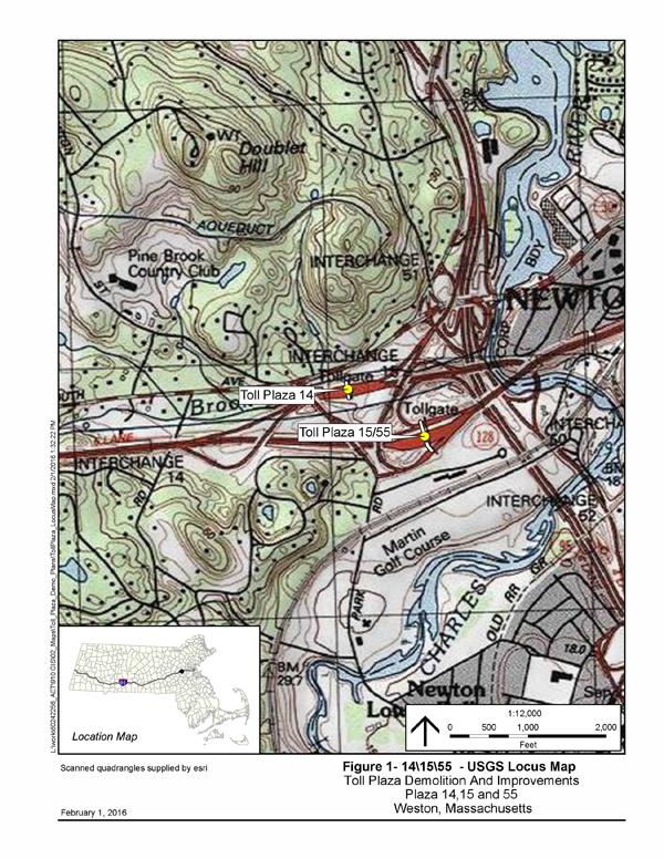
1 DESIGN PUBLIC HEARING JUNE 22, 2016 AT TOWN HALL AUDITORIUM 11 TOWN HOUSE ROAD WESTON, MASSACHUSETTS 7:00 PM FOR THE PROPOSED DEMOLITION OF LEGACY TOLL PLAZAS ALONG I-90 DISTRICT 6 PLAZAS 14, 15 AND 55 INCLUDING NEW BRIDGE W MASSDOT Project No Bridge No. W Roadway/Bridge Project Management IN THE TOWN OF WESTON, MASSACHUSETTS COMMONWEALTH OF MASSACHUSETTS MASSACHUSETTS DEPARTMENT OF TRANSPORTATION HIGHWAY DIVISION THOMAS J. TINLIN HIGHWAY ADMINISTRATOR PATRICIA A. LEAVENWORTH, P.E. CHIEF ENGINEER 1
2 THE COMMONWEALTH OF MASSACHUSETTS MASSACHUSETTS DEPARTMENT OF TRANSPORTATION HIGHWAY DIVISION NOTICE OF A DESIGN PUBLIC HEARING Project File No A Design Public Hearing will be held by MassDOT to discuss the proposed elimination of the direct Access from the Liberty Mutual Facility to and from I-95 as a result of the Demolition of Legacy Toll Plazas along I-90 (including new bridge W ) project in Weston, MA. WHERE: Town Hall Auditorium 11 Town House Road Weston, MA WHEN: Wednesday, June 22 7:00 PM PURPOSE: The purpose of this hearing is to provide the public with the opportunity to become fully acquainted with the proposed project. All views and comments made at the public hearing will be reviewed and considered to the maximum extent possible. PROPOSAL: The proposed work will eliminate the direct access from the Liberty Mutual facility within the project area to and from the I-90 & I-95 Interchange. The proposed project also consists of removal of the existing toll plaza administrative and utility building(s); staged removal of the existing toll booths, gantries, canopies and access tunnels; removal of existing parking lot(s) and parking access drives; and geometric modifications and roadway reconstruction to the I-90 & I-95 Interchange. A secure right-of-way is necessary for this project. Acquisitions in fee and permanent or temporary easements may be required. The Commonwealth of Massachusetts is responsible for acquiring all needed rights in private or public lands. MassDOT s policy concerning land acquisitions will be discussed at this hearing. Written views received by MassDOT subsequent to the date of this notice and up to five (5) days prior to the date of the hearing shall be displayed for public inspection and copying at the time and date listed above. Plans will be on display one-half hour before the hearing begins, with an engineer in attendance to answer questions regarding this project. A project handout will be made available on the MassDOT website listed below. Written statements and other exhibits in place of, or in addition to, oral statements made at the Design Public Hearing regarding the proposed undertaking are to be submitted to Patricia A. Leavenworth, P.E., Chief Engineer, MassDOT, 10 Park Plaza, Boston, MA 02116, Attention: Highway Design Project File No Such submissions will also be accepted at the hearing. Mailed statements and exhibits intended for inclusion in the public hearing transcript must be postmarked within ten (10) business days of this Design Public Hearing. Project inquiries may be ed to dot.feedback.highway@state.ma.us This location is accessible to people with disabilities. MassDOT provides reasonable accommodations and/or language assistance free of charge upon request (including but not limited to interpreters in American Sign Language and languages other than English, open or closed captioning for videos, assistive listening devices and alternate material formats, such as audio tapes, Braille and large print), as available. For accommodation or language assistance, please contact MassDOT s Chief Diversity and Civil Rights Officer by phone ( ), fax ( ), TTD/TTY ( ) or by (MassDOT.CivilRights@dot.state.ma.us). Requests should be made as soon as possible prior to the hearing, and for more difficult to arrange services including sign-language, CART or language translation or interpretation, requests should be made at least ten (10) business days before the hearing. In case of inclement weather, hearing cancellation announcements will be posted on the internet at THOMAS J. TINLIN HIGHWAY ADMINISTRATOR PATRICIA A. LEAVENWORTH, P.E. CHIEF ENGINEER

3 MassDOT Public Hearing Handout Introductory Letter Dear Concerned Citizen: The Massachusetts Department of Transportation (MassDOT) is committed to building and maintaining a transportation infrastructure that is both safe and efficient for all who use our roadways, bridges, bicycle facilities and pedestrian paths, while maintaining the integrity of the environment. As part of the design process for this project, we are conducting this public hearing to explain the proposed improvements, listen to your comments and answer any questions you may have. At the conclusion of the hearing, MassDOT will review all of your comments and, where feasible, incorporate them into the design of the project. We recognize that road and bridge construction can create inconveniences for the public. MassDOT places a great deal of emphasis on minimizing the temporary disruptive effects of construction. MassDOT encourages input from local communities and values your opinions. Please be assured that we will undertake no project without addressing the concerns of the community. Sincerely, Patricia A Leavenworth, P. E. Chief Engineer
4 WHAT IS A PUBLIC HEARING? WHY A PUBLIC HEARING? To provide an assured method whereby the Commonwealth of Massachusetts can furnish to the public information concerning the State s highway construction proposals, and to afford every interested resident of the area an opportunity to be heard on any proposed project. At the same time, the hearings afford the Commonwealth an additional opportunity to receive information from local sources which would be of value to the State in making its final decisions to what design should be advanced for development. WHY NOT A VOTE ON HIGHWAY PLANS? The hearings are not intended to be a popular referendum for the purpose of determining the nature of a proposed improvement by a majority of those present. They do not relieve the duly constituted officials of a State highway department of the necessity for making decisions in State highway matters for which they are charged with full responsibility. WHAT DOES A PUBLIC HEARING ACCOMPLISH? It is designed to ensure the opportunity for, or the availability of, a forum to provide factual information which is pertinent to the determination of the final alternative considered by the state to best serve the public interest, and on which improvement projects are proposed to be undertaken. It is important that the people of the area express their views in regard to the proposal being presented, so that views can be properly recorded in the minutes of the meeting. These minutes will be carefully studied and taken into consideration in the determination of the final design.
5 TO SAFEGUARD THE PROPERTY OWNER If your property, or a portion of it, must be acquired by the State for highway purposes in the interest of all people of the Commonwealth, your rights are fully protected under the law. Briefly, here are some of the answers to questions you might ask. 1. WHO CONTACTS ME? Representatives of the Right of Way Bureau of the Massachusetts Department of Transportation s Highway Division. They will explain the impacts and your rights as protected under Massachusetts General Laws Chapter WHAT IS A FAIR PRICE FOR MY PROPERTY? Every offer is made to ensure that an equitable value is awarded to you for the property, or to appraise the damage to the property as a result of the acquisition. MassDOT appraisers, independent appraisers, MassDOT Review Appraisers and a Real Estate Appraisal Review Board may all contribute in arriving at an award of damages. The State also pays a proportionate part of the real estate tax for the current year for fee takings, and interest from the date the property is acquired to the payment date, on all impacts. 3. MUST I ACCEPT THE DEPARTMENT S OFFER? No. If, after the figure established as market value has been offered to the owner, the owner feels he or she is not being offered a fair price, he or she has the right, within three years, to appeal to the courts. Pending a court decision, he or she can be paid on a protanto basis (or for the time being ) that in no way prejudices the court appeal. 4. WHAT WILL HAPPEN TO MY HOUSE? The owner will have the opportunity to buy back his or her house, provided he or she has a location to which it can be moved, and the proper permits for its removal. If the owner does not wish to repurchase, the house will be advertised for bids. The highest bidder, who must also have a location and permits for removal, will be awarded the house. Otherwise, the structure will be slated for demolition. 5. WHAT HAPPENS IF I MUST RELOCATE? In addition to the market value of the property, the Department pays certain relocation benefits for both owners and tenants of acquired residences and businesses who meet eligibility requirements. Assistance in relocation is also provided. Department brochures are available for details on these benefits.
6
7 Project Location The existing toll plaza demolition project is located in the Town of Weston, Massachusetts. It is part of a system to system interchange between I-90 and I-95. The project is part of the National Highway System (NHS) and is considered a limited access highway. The toll plaza locations are along I-90 just west of the I-95. Purpose The goal of this project is to remove roadway and roadside infrastructure no longer needed following the conversion from the existing ticket and barrier system tolls to an All Electronic Tolling System (AETS). The removal of the existing 24 toll plazas will result in traffic mobility and safety improvements. Existing Condition The Massachusetts Turnpike System is comprised of the 124-mile Western Turnpike (Interstate Highway I-90) between the New York state line and Exits 14/15/55 in Weston, and the Metropolitan Highway System (MHS) which includes the urbanized part of I-90 as well as the Sumner/Callahan Tunnels, the Williams Tunnel, and the Tobin Bridge. The Turnpike toll plazas employ lanes with manual, dedicated Electronic Toll Collection (ETC), automatic ticket issuing machine (ATM), or dual model manual/etc toll collection. Also, at each plaza, one or more of the physical lanes toward the middle of the plaza are reversible to better match transaction processing capacity to the directionality of the traffic flow. Wide lanes are provided at each toll plaza to accommodate wide load trucks. Figure 1 below shows the toll plaza configuration at Toll Plaza 14. Toll Plaza 14 (Weston) provides I-90 connections to I-90 west, I-95 (Route 128), Route 30 and River Street. Figure 1: Toll Plaza 14
8 Figure 2 shows the toll plaza configuration at Toll Plaza 15. Toll Plaza 15 is located on the I-90 mainline in Weston and is the terminus of the Western Turnpike. Figure 2: Toll Plaza 15 Figure 3 below shows the toll plaza configuration for Toll Plaza 55. Toll Plaza 55 (Weston) has two locations on both sides of Toll Plaza 15. The toll plaza south of Plaza 15 provides eastbound access to I-90 from Route 30, Park Road, and Riverside Drive. The plaza north of Toll Plaza 15 provides access from I-90 westbound to I-95 (Route 128), Route 30, Park Road, and Riverside Drive. Figure 3: Toll Plaza 55Scope of Work
9 Scope of Work The work to be performed under this contract consists of, but is not limited to, the removal of roadway, and roadside infrastructure no longer needed following the implementation of the I-90 All Electronic Tolling System at Plaza 14 (Weston) and Plaza 15 and 55 (Weston). The work, in general, shall consist of the following: PLAZA 14 (Weston) staged removal of the existing toll booths, gantries and canopies and access tunnels; removal of a portion of the tandem truck lot operation; modifications to the connector on (Ramp J) and off ramps (Ramp L) to I-95 to meet the higher speed required for this connector ramp system; and the construction of a new relocated I-90 westbound to I-95 ramp (Ramp R) further to the west to improve the existing weaving condition. This ramp replaces the existing short weave ramp (Ramp H2) as shown and called for on the Contract Documents. PLAZA 15 and 55 (Weston) removal of the existing toll plaza administrative and utility building(s); staged removal of the existing toll booths, gantries and canopies and access tunnels; removal of the existing ramp connections to the leased Liberty Mutual property; modifications to the existing I-90 eastbound and westbound mainline to provide for the increase in travel speed associated with the removal of the toll plazas. The modifications include lowering the existing mainline of I-90 approximately six (6) feet and introducing the required 6% superelevation all as shown and called for on the Contract Documents. In support of the toll plaza demolition a preferred roadway alternative was developed that addresses some of the impacts and constraints remaining once the toll plaza are removed. Figure 4 shows the preferred alternative configuration. Note that the following ramps currently serve this location: North side: Ramp H2 I-90 westbound Off-Ramp for vehicles accessing I-95 (Route 128) northbound and southbound. Ramp K I-90 westbound Off-Ramp for vehicles accessing Park Road and Access Road. South side: Ramp G I-90 eastbound On-Ramp for vehicles originating from I-95 northbound and southbound, River Road and Route 30. Ramp P I-90 eastbound On-Ramp for vehicles originating from Park Road and Riverside Drive. The preferred alternative includes construction of a new ramp ( Ramp R ) to replace the existing I-90 westbound Off-Ramp to I-95 (Ramp H2). The new exit Ramp R will provide one 12-foot wide lane with an eight-foot inside shoulder and 2-foot outside shoulder approximately 1,300 feet west of its former H2 location, and join with Ramp J (traffic exiting from I-90 eastbound) approximately 300 feet in advance of the location of former Toll Plaza 14. In the vicinity of former Toll Plaza 15 (on the I-90 mainline), the preferred alternative provides two eastbound travel lanes and three westbound travel lanes. All travel lanes are 12 feet wide and
10 shoulder widths vary. A concrete median separates travel in eastbound and westbound directions. A guard rail is provided along the outside eastbound shoulder. Ramps G and P will approach the former eastbound Toll Plaza 55 as single lanes and then merge into one lane (Ramp P) immediately east of the former toll plaza. The gore between these two ramps is lengthened. Ramp P is 12 feet wide with a 2-foot outside shoulder and enter I-90 eastbound in its own (3 rd lane). The Ramp K I-90 westbound off-ramp is one lane 12 feet wide with an inside shoulder width of 2 feet and an outside shoulder width of eight feet. This ramp exit occurs approximately 180 feet in advance of the former toll plaza location. A guardrail is provided along the outside shoulder of Ramp K. The removal of the Toll Plazas 15 and 55 and the proposed roadway geometry allows for the narrowing of roadway in this vicinity from 22 total toll lanes to seven travel lanes. Currently, the existing toll plazas have a posted speed limit of 15 MPH. The proposed configuration will provide roadway design speeds of 60 MPH at former Toll Plaza 15 (along the I-90 mainline), and 30 MPH at former Toll Plaza 55 (I-90 entering/exiting vehicles). The existing toll plaza building will be eliminated. The existing toll plaza gantry and pedestrian tunnels will be removed to a depth of 4.5 feet. Minor modifications will be made to the toll plaza area to meet the proposed cross section, including the need to mill and overlay, and restripe the existing roadway. The modifications at Toll Plazas 14, 15/55 will include approximately 249,000 square feet of full depth pavement reconstruction and approximately 380,000 square feet of pavement mill and overlay, and restriping. There are no design exceptions for Toll Plazas 15 and 55 other than the existing substandard features at the tie in area outside of the project limits.

11 Figure 4: Toll Plazas 14/15/55 Preferred Alternative
12 Maintenance of Traffic During Construction The primary construction elements at Toll Plazas 14 and 15/55 are the demolition of the existing tolling structures and the subsequent restoration of the roadway area impacted by the removal of the plazas. Additional work includes roadway reconstruction upstream and downstream of the plaza areas to accommodate appropriate transitions through the legacy plaza locations, and to provide proper horizontal and vertical alignments. Below is a detailed description of the major components of the project during construction phase for Plaza 14, with a similar sequence planned for Plazas 15/55. For both plazas, the base condition will be the AETS Go-Live roadway and lane configurations. Peak hour traffic volumes have been evaluated at each plaza, and sufficient capacity will be provided to accommodate the highest hourly traffic demand during each phase of construction. Toll Plaza 14 Toll Plaza 14 construction staging plans are shown in Figure5. Construction Phase 1 (not shown in figure) includes construction of a new ramp (Ramp R) that will eventually replace the existing I-90 westbound Off-Ramp to I-95 (Ramp H2). The new exit Ramp R will provide one 12-foot wide lane approximately 1,300 feet west of its former location. In addition, temporary pavement will be installed for approximately 130 feet along the outside exiting lane (northeast of the Toll Plaza 14). Construction Phase 2 (see Figure5) consists of removing and restoring the central portion of Toll Plaza 14, which includes removal of lanes #4-9, and toll booths D, E, F, G, and H. I-90 entering (westbound) vehicles originating from local streets and I-95 southbound (Ramp D) and I-95 northbound will utilize existing lanes #10, #11 and #12. The outside lane (#13) will not be used. Three lanes in each direction will be provided. Since Ramp H-2 is closed during this phase, traffic is diverted to new Ramp R. I-90 exiting (eastbound) vehicles originating from I-90 westbound (the new Ramp R) and I-90 eastbound (Ramp J) will utilize existing lanes #1, #2 and #3. Existing toll booths C and I and temporary double faced concrete barriers will separate travel lanes from the central construction zone. Construction of a median will take place during this phase. During construction Phase 3, the vehicular travel lanes will shift to the center, and the toll plaza demolition and roadway reconstruction will occur on both (north and south) sides of the toll plaza area. On the north side, the work zone will extend approximately 1,800 linear feet total in the former toll plaza area. On the south side, the work zone will extend approximately 1,200 linear feet total in the former toll plaza area. The existing toll plaza building, plus lanes #1, #2, #3, #10, #11, #12 and #13, and toll booths A, B, C, I, J, K, L and M will be removed during this phase. The two travel lanes north of the toll plaza area, that will be used for I-90 entering (westbound) vehicles originating from I-95 northbound, will taper down to one lane, which will align with the single lane provided for I-90 entering (westbound) vehicles originating from local streets and I- 95 southbound (Ramp D). These two ramps will meet in advance of the toll plazas to provide two 11-foot wide westbound lanes through the toll plaza area. One-foot wide shoulders will be provided on both sides of the eastbound direction. The gore between these two ramps will be temporarily extended by approximately 240 feet using reflective traffic drums. The two lanes that will be used for I-90 exiting (eastbound) vehicles originating from I-90 eastbound (Ramp J) will taper down to one lane, which will align with I-90 exiting (eastbound)
13 vehicles originating from I-90 westbound (the new Ramp R). The taper to channel the vehicular merge from two lanes to one on Ramp J, and the gore between Ramps J and R, will be temporarily marked with reflective traffic drums and temporary pavement markings. In the vicinity of the former toll plazas, the temporary eastbound lanes provided will be 12-feet wide. Two-foot wide shoulders will be provided on both sides of the eastbound direction and an inside median that varies between 9-13 feet wide will separate the eastbound and westbound travel lanes. A shoulder mentioned previously and temporary double faced concrete barriers will separate the two outside lanes from the work zones on either side. The construction work zone during Phase 4 (not shown in figure) includes the two gore areas on either side of the former toll plaza area. For I-90 entering (westbound) vehicles, both approaches from I-95 northbound and Ramp D will taper from two lanes to one in advance of the gore area. For I-90 exiting (eastbound) vehicles, the new Ramp R provides a single lane approach, while Ramp J tapers from two lanes to one lane in advance of the gore area. Temporary double faced concrete barriers will separate each of these ramp lanes from the gore area construction zone. For construction Phase 4, the two travel lanes for I-90 entering (westbound) will be 12-foot wide lanes, and an additional (third) I-90 exiting (eastbound) lane (12 feet wide) will be provided. The inside shoulder in the westbound direction will be two-feet wide, while the inside shoulder in the eastbound direction will be four-feet wide. Eastbound and westbound traffic will be separated by a center median that varies between 9-13-feet wide. In the vicinity of the former toll plazas, the outside eastbound shoulder will be eight feet wide, and the outside westbound shoulder will be 12 feet wide. The Final configuration will remain the same as Phase 4, with the additional wider inside and outside shoulders in both directions. Guardrails will be constructed along the outside lanes in both directions. Figure 5: Toll Plaza 14 Construction Plan
14 Toll Plazas 15 & 55 Toll Plazas 15 and 55 construction staging plans are shown in Figure6. Construction Phase 1 (not shown in the figure) includes construction of a new ramp (Ramp R) previously mentioned in the Toll Plaza 14 construction staging description. In addition, temporary pavement will be installed for approximately 80 feet in between and in advance of the westbound lanes for Toll Plazas 15 and 55. In Construction Phase 2 (see Figure6), Ramp H2 is closed, and I-90 westbound Off-Ramp traffic to I-95 is diverted to the new Ramp R. Advanced signage will be installed directing vehicles to the new exit. Construction Phase 2 includes removal and restoration of the central portions of Toll Plaza 15, which includes removal of lanes #7-14, and toll booths G, H, I, J, K, L and M. In the westbound direction, the existing three outside lanes (#15, #16 and #17) will be used for mainline I-90 traffic, and two of the center Plaza 55 lanes (lanes #19 and #20) on Ramp K will be used for vehicles exiting I-90. In the eastbound direction, the existing two outside lanes (#5 and #6) will be used for mainline I-90 traffic, and the two outside Plaza 55 lanes (lanes #1 and #2) on Ramp P will be used for vehicles entering I-90. Lane channelization along travel lanes and gore areas will be marked using temporary striping and reflective traffic drums. Toll booths F and N, plus temporary double faced concrete barriers will separate travel lanes from the central construction zone. Construction of a median barrier on I-90 will take place during this phase. During construction Phase 3, the vehicular travel lanes will shift to the center, and the toll plaza demolition and roadway reconstruction will occur on both (north and south) sides of the toll plaza area between temporary I-90 mainline travel lanes and entering/exiting (Plaza 55) lanes. On the north side, the work zone extends approximately 1,300 linear feet total in the toll plaza area. On the south side, the work zone extends in excess of approximately 2,800 linear feet in the toll plaza area. Lanes #2-6 and #15-18 and toll booths B, C, D, E, F, N and O will be removed during this phase. I-90 mainline vehicles will use three centrally located 12-foot wide westbound lanes and two 12- foot wide eastbound lanes. A one to two-foot wide inside shoulder and median barrier will separate eastbound and westbound traffic. An outside shoulder of one to two feet and temporary double faced concrete barriers will separate the two outside travel lanes from the work zones on either side. I-90 exiting vehicles (Plaza 55 on the north side) will continue to use the same two lanes (#19 and #20) as during construction Phase 2. I-90 entering vehicles (Plaza 55 on the south side) will use only the existing outside lane (#1). Toll booths A and P, as well as temporary double faced concrete barriers will separate the entering/exiting lanes from the central construction zone. The construction work zone during Phase 4 includes all of the exiting (westbound) side of Plaza 55 and all but the newly constructed inside lane of the entering (eastbound) side of Plaza 55. This phase also includes demolition of the existing toll plaza building on the south side of the plazas. Two additional reconstruction areas include the outside section of the I-90 westbound mainline in advance of the former toll plaza area, and an area along the outside portion of Ramp K approximately 240 linear feet. For I-90 mainline westbound vehicles during construction Phase 4, three 12-foot wide lanes will be provided in the central portion of the roadway with a two-foot inside shoulder. Westbound vehicles exiting I-90 will be provided with a 12-foot wide one-lane exit approximately 170 feet in advance of the former toll booths and a varied inside shoulder and eight-foot wide outside shoulder. For I-90 mainline eastbound vehicles, two 12-foot wide lanes with a varied inside and
15 outside shoulders. A center median (varied width) will separate I-90 eastbound and westbound vehicles. Eastbound vehicles entering I-90 will be provided with a newly constructed 12-foot wide single lane along the inside portion of Plaza 55. Reflective drums will be provided along the inside shoulder and a temporary double faced concrete barrier will separate this lane from the construction zone to the outside (south). During Phases 3 and 4, construction may require the temporary closure of the I-90 exit ramp that connects with Park Road and Route 30 (Ramp K). If this closure occurs, a detour would be necessary for these vehicles. The detour would involve drivers taking the new Ramp R to the ramp for I-95 northbound, to the off ramp to Route 30, and then turning left on Route 30 to Park Road. This detour is shown in Figure 7. Figure 6: Toll Plazas 15 and 55 Construction Plan
16 Figure 7: Temporary Detour for Ramp K Construction
17 Construction Phase 5 (not shown in figure) will include all milling and pavement overlay operations, plus installation of signs, pavement markings, and other traffic management devices. The layout for the Final configuration is the same as under Phase 4, with the exception of the eastbound vehicles entering I-90 (former Plaza 55). This lane will be shifted to the southernmost portion of the former toll plaza area. It will consist of a newly constructed single 12-foot wide lane with an eight-foot wide inside shoulder, a two foot-wide outside shoulder, and guardrails on both sides. Project Status The plans on display this evening are 100% (design stage) complete. Comments from this evening will be reviewed and addressed in the final design. The process with continue to the Plans Specifications and Estimate and the award of the construction contract. Construction is anticipated to be completed over a 24 month period. Project Costs At this time, the estimated participating cost of construction is approximately $23,779, Funding for the construction of this project will be by the Commonwealth of Massachusetts.
18 THE COMMONWEALTH OF MASSACHUSETTS MASSACHUSETTS DEPARTMENT OF TRANSPORTATION HIGHWAY DIVISION NON FEDERAL AID PROJECT WESTON, MA DEMOLITION OF LEGACY TOLL PLAZAS ALONG I-90 DISTRICT 6 PLAZAS 14, 15 AND 55 INCLUDING NEW BRIDGE W Project File No This sheet is provided for your comments. Your input is solicited and appreciated. Please return your sheet, with comments, to a staff member at the meeting, or mail to: Patricia A. Leavenworth, P.E., Chief Engineer MassDOT Highway Division 10 Park Plaza, Boston, MA Attn: Roadway/Bridge Project Management The final date for receipt of written statements and exhibits for inclusion into the official hearing transcript will be ten (10) days after the Public Hearing. PLEASE TYPE OR PRINT LEGIBLY. Name: Title: Organization: Address:
19 Please Fold and Tape Please Place Appropriate Postage Here Patricia A. Leavenworth, P.E. Chief Engineer MassDOT Highway Division 10 Park Plaza Boston, MA RE: Public Hearing DEMO OF LEGACY TOLL PLAZAS ALONG 1-90 DISTRICT 6 TOWN OF WESTON Project File No Attn: Roadway/Bridge Project Management
Demolition of Ramp C (SN ): Westbound Ontario Street to Eastbound I-90/94) over I-90/94 (JF Kennedy Expressway)
: Westbound Ontario Street to Eastbound I-90/94) over I-90/94 (JF Kennedy Expressway)") I-90/94 (Kennedy Expressway) at Ohio Street Structure Replacement and Rehabilitation Section Number 0303-474HB-R D-91-177-09 Contract 60F63 Cook County, Region One, District One City of Chicago Project
I-90/94 (Kennedy Expressway) at Ohio Street Structure Replacement and Rehabilitation Section Number 0303-474HB-R D-91-177-09 Contract 60F63 Cook County, Region One, District One City of Chicago Project
Exit 61 I-90 Interchange Modification Justification Study
 Exit 61 I-90 Interchange Modification Justification Study Introduction Exit 61 is a diamond interchange providing the connection between Elk Vale Road and I-90. Figure 1 shows the location of Exit 61.
Plan Preparation Checklist
 Appendix D Plan Preparation Checklist It is the responsibility of the Designer to complete and submit this checklist along with all required drawings for OUC (EFP) Review. All drawings submitted for OUC
Charlton/Oxford Route 20 Reconstruction Project
 Public Informational Meeting February 1, 2017 Oxford High School Charlton/Oxford Route 20 Reconstruction Project Project File No. 602659 2014 HDR, Inc., all rights reserved. Public Informational Meeting
CHAPTER 2C - PRELIMINARY DESIGN. General... 2C-1. Review of Work Load... 2C-2 Establishing Priorities... 2C-2
 SECTION 2C - 1 - PROJECT REVIEW CHAPTER 2C - PRELIMINARY DESIGN General... 2C-1 SECTION 2C - 2 - COORDINATING TIME SCHEDULES Review of Work Load... 2C-2 Establishing Priorities... 2C-2 SECTION 2C 3 - REVIEW
Appendix D. Traffic Noise Analysis Report. I-94 St. Michael to Albertville Minnesota Department of Transportation
 Appendix D Traffic Noise Analysis Report I-94 St. Michael to Albertville Minnesota Department of Transportation Traffic Noise Analysis Report I-94 St. Michael to Albertville Project SP 8680-172 Report
King Mill Lambert DRI# 2035 Henry County, Georgia
 Transportation Analysis King Mill Lambert DRI# 2035 Henry County, Georgia Prepared for: The Alter Group, Ltd. Prepared by: Kimley-Horn and Associates, Inc. Norcross, GA Kimley-Horn and Associates, Inc.
Appendix L Noise Technical Report. Rehabilitation and Restoration of the Longfellow Bridge
 Appendix L Noise Technical Report Rehabilitation and Restoration of the Longfellow Bridge Noise Technical Report Rehabilitation and Restoration of the Longfellow Bridge Boston, MA May, 2011* Prepared by
Maintenance of Traffic sequence of operations including any phasing and detour maps;
 All Local-let projects are required to have a Stage 2 submittal to the LPA Manager for review. The only exceptions are 2-lane resurfacing, striping, guardrail, and raised pavement markers, unless otherwise
State Road A1A North Bridge over ICWW Bridge
 Final Report State Road A1A North Bridge over ICWW Bridge Draft Design Traffic Technical Memorandum Contract Number: C-9H13 TWO 5 - Financial Project ID 249911-2-22-01 March 2016 Prepared for: Florida
Memorandum 1.0 Highway Traffic Noise
 Memorandum Date: September 18, 2009 To: Chris Hiniker, SEH From: Stephen B. Platisha, P.E. Re: Updated CSAH 14 Noise Analysis The purpose of this memorandum is to provide the results of the revised traffic
BOSTON EVERETT HORIZON WAY BROADWAY ALFORD ST BOW ST BOSTON CITY LINE EVERETT CITY LINE DEXTER ST MYSTIC ST COURTLAND ST LYNDE ST THORNDIKE ST
 BOSTON HORIZON WAY ALFORD ST BROADWAY BOSTON CITY LINE CITY LINE MANHOLE #101 (STA 5+00) BOW ST DEXTER ST ST LYNDE ST THORNDIKE ST COURTLAND ST RIVER PROP (TYP) ROBIN ST BETTY ST 50 500 1. BASELINE STATIONING
Appendix G. Visual Simulations and Illustrations
 Appendix G Visual Simulations and Illustrations 5TH AVE AV E N View ewshe ed 5 SHORELINE N 185TH ST egment B gment A 26 NE 185th Street Station (A1, A3, A5, A7, A10, A11) 25 24 23 22 21 NE 180TH ST 99
CHAPTER 14: TRAFFIC SIGNAL STANDARDS Introduction and Goals Administration Standards Standard Attachments 14.
 14.00 Introduction and Goals 14.01 Administration 14.02 Standards 14.03 Standard Attachments 14.1 14.00 INTRODUCTION AND GOALS The purpose of this chapter is to outline the City s review process for traffic
Expressway Authority Standards for Preparation of Signing and Pavement Marking Plans
 Expressway Authority Standards for Preparation of Signing and Pavement Marking Plans Expressway Authority Standards for Preparation of Signing and Pavement Marking Plans 408 414 417 429 451 528 CENTRAL
CHAPTER 1: TITLE SHEET and GENERAL LAYOUT
 CHAPTER 1: TITLE SHEET and GENERAL LAYOUT AREA OF ENVIRONMENTAL SENSITIVITY It is important to show the areas of environmental sensitivity in the plan to make sure these areas are not impacted. These locations
The Shoppes at Forney Crossings
 F M 548 U.S. HWY 80 U.S. HWY 80 F M 688 F M 548 COOL SPRINGS F M 1641 F M 548 TROPHY BUGLE CALL PHESANT WHITE PORCH SPINAKER The Shoppes at Forney Crossings 18' 14'-8" 18' 15'-8 1 2 " 14' 7' 23'-0" 21'-0"
Updated: April 7, 2016
 Updated: April 7, 2016 Hwy 36 to Lexington Ave. Add a lane in each direction Recommend a MNPASS Lane Several spot improvements to roadway included Concrete pavement Noise walls will be evaluated Replace
REQUEST FOR PROPOSAL
 REQUEST FOR PROPOSAL Engineering Design Services for the Preliminary Engineering of Lake Nepessing/Davison/Genesee Intersection Improvements Sections 1, 2, 11 and 12 of Elba Township Lapeer County, Michigan
Move In Directions for First-year and Transfer Students Douglass Campus Gibbons Residence Hall A & B
 Move In Directions for First-year and Transfer Students Douglass Campus Gibbons Residence Hall A & B General Instructions: Print directions and name of assigned building. Place the name of your residence
Guide Sign Policy for Secondary State Highways Edition
 Massachusetts Highway Department, Ten Park Plaza, Boston, MA 02116-3973 ` Guide Sign Policy for Secondary State Highways 2005 Edition Revised September 2005 1. PURPOSE The Massachusetts Highway Department
Update: July 20, 2012
 Location and Design Manual, Volume 3 ODOT Office of CADD and Mapping Services Update: July 20, 2012 ** NOTE: All metric references have been removed from this manual. ** PREFACE REVISIONS Glossary of Terms
HIGHWAY WORK ZONE DATA COLLECTION INSTRUMENT
 HIGHWAY WORK ZONE DATA COLLECTION INSTRUMENT Case ID: MI Date of Investigation Respondent Employer Information 1. Is the employer the primary contractor or a subcontractor working at the site? Victim Information
Study Description. November 29, Overpass Road Alternatives Public Workshop
 Overpass Road Alternatives Public Workshop November 29, 2012 Welcome to the Alternatives Public Workshop for proposed improvements to Overpass Road in Pasco County. Pasco County (the County), in coordination
DIVISION PAVEMENT MARKINGS AND MARKERS
 DIVISION 61 66 PAVEMENT MARKINGS AND MARKERS 66.01 SCOPE: The purpose of these specifications is to describe the minimum requirements of the City of Chesapeake for pavement markings and shall be in addition
Ohio Department of Transportation Office of Roadway Engineering January 18, 2013
 Ohio Department of Transportation Office of Roadway Engineering January 18, 2013 To: Holders of the Traffic Standard Construction Drawings (SCDs) and Plan Insert Sheets (PISs) As of January 18, 2013, eighteen
Automated Machine Guidance
 Design Manual Chapter 5 - Roadway Design 5H - Automated Machine Guidance 5H-1 Automated Machine Guidance A. Concept Automated machine guidance (AMG) for grading is a process in which grading equipment,
September 6, 2018 CITY OF BERKELEY SHATTUCK RECONFIGURATION AND PEDESTRIAN SAFETY PROJECT SPECIFICATION NO C ADDENDUM NO.
 Department of Public Works Transportation Division September 6, 2018 CITY OF BERKELEY SHATTUCK RECONFIGURATION AND PEDESTRIAN SAFETY PROJECT SPECIFICATION NO. 17-11090-C ADDENDUM NO. 3 Dear Bidder: The
Survey Data and TOPO Checklist
 Checklists Survey Data and TOPO Preliminary Plan Field Review Plans o Field Review Erosion Control Right-of-Way and Utility Meeting Plans Final Plan Field Review Plans Methods of Plan Markups Plan-in-Hand
Proposed Watertown Plan Road Interchange Evaluation Using Full Scale Driving Simulator
 0 0 0 0 Proposed Watertown Plan Road Interchange Evaluation Using Full Scale Driving Simulator Kelvin R. Santiago-Chaparro*, M.S., P.E. Assistant Researcher Traffic Operations and Safety (TOPS) Laboratory
GCG ASSOCIATES, INC. February 8, Mr. Nathaniel Strosberg, Town Planner 101 Main Street Town of Ashland Ashland, MA 01721
 GCG ASSOCIATES, INC. CIVIL ENGINEERING AND LAND SURVEYING 84 Main Street Wilmington, Massachusetts 01887 Phone: (978) 657-9714 Fax: (978) 657-7915 February 8, 2016 Mr. Nathaniel Strosberg, Town Planner
PROCEDURE FOR PROCESSING WORKING DRAWINGS
 PROCEDURE FOR PROCESSING WORKING DRAWINGS MAY 2005 Procedure for Processing Working Drawings GENERAL: The procedure for the review and processing of working drawings provide for two primary types of drawings,
Straight Line Diagram. Lawrence 37. January 2010
 Straight Line Diagram Lawrence 37 January 2010 This document was produced by the Pennsylvania Department of Transportation (PENNDOT) as an internal management tool for State maintained highways and is
SECTION 3 SUBMISSION REQUIREMENTS
 SECTION 3 SUBMISSION REQUIREMENTS Table of Contents Page No 3.1 GENERAL... 3 3.2 COORDINATION WITH OUTSIDE AGENCIES... 3 3.3 PRELIMINARY DESIGN... 4 3.4 FINAL DESIGN... 5 3.4.1 GENERAL... 5 3.4.2 PHASE
Appendix B: Transportation B-10 Toll Plaza Analysis
 Appendix B: Transportation B-10 Toll Plaza Analysis TRAFFIC-DESIGN STUDIES TZB TOLL PLAZA ANALYSES STUDY ASSUMPTIONS Study Goal: Provide assessment of current design concept for toll plaza operations under
1.0 Introduction. 1.1 Introduction. 1.2 Project Background
 1.0 Introduction 1.1 Introduction This document is the Draft Environmental Impact Statement (DEIS) for the Port Authority of New York & New Jersey s (Port Authority) proposed Goethals Bridge Replacement
Contract for Artist Professional Services and Copyright
 Contract for Artist Professional Services and Copyright This Contract constitutes an agreement between the National Gallery of Canada and a Canadian living artist, hereinafter referred to, respectively,
CITY OF SCHENECTADY NEW YORK CITY PLANNING COMMISSION
 CITY OF SCHENECTADY NEW YORK CITY PLANNING COMMISSION Christine S. Primiano, Principal Planner Room 14, City Hall, Jay Street SCHENECTADY, NY 12305-1938 518.382.5147 cprimiano@schenectadyny.gov www.cityofschenectady.com
INNOVATIVE DEPLOYMENT OF DYNAMIC MESSAGE SIGNS IN SAFETY APPLICATIONS
 INNOVATIVE DEPLOYMENT OF DYNAMIC MESSAGE SIGNS IN SAFETY APPLICATIONS L.A. Griffin Director of Expressway Operations, Orlando-Orange County Expressway Authority 4974 ORL Tower Road Orlando, FL 32807 (407)
Minor Site Plan Application
 Section 496-11.3.6 of the City Code: Minor Site Plan Review allows for review of the site design of routine development applications that are eligible to be processed administratively. Procedure 1. If
Working Drawing Manual
 Working Drawing Manual 2012 Table of Contents Section 1 Working Drawing Types... 1 1.1 General... 1 Section 2 Processing Steps... 1 2.1 Project Manager... 1 2.2 Engineering Document Unit... 2 2.3 Contractor...
Work Type Definition and Submittal Requirements 14.6 Signing Plan Design & Special Provisions. Work Type Definition
 Work Type Definition Pages 1-3 detail the work type definition. In order to become pre-qualified for this work type, please see the Work Type Submittal Requirements on pages 4-6. I. Description Signing
OCNI/Bruce Power Suppliers Day
 OCNI/Bruce Power Suppliers Day November 8 2017 2017 Bruce Power Suppliers Day Dear Exhibitor, At OCNI we would like to welcome you to the 2016 Bruce Power Suppliers Day in Tiverton, Ontario. This event
Appendix B: Noise Study
 Appendix B: Noise Study creating remarkable solutions for a higher quality of life NOISE STUDY Interstate 55 Route PP to County Road 311 Prepared for: MoDOT PROJECT NO. J010956 November 2014 Prepared
TYPICAL SECTION OF IMPROVEMENT
 ...\plans\0_prelim\07c_sh0.dgn /8/009 DIV. STATE COUNTY FILE OJECT TYPICAL CTION OF IMOVEMENT SC 7.0658A8 I-7 NORTHBOUND I7 SOUTHBOUND I7 8 8 0 8 VARIABLE (E CROSS CTIONS) : CONST..5.5 CONST. (
Major Site Plan Application
 Procedure Section 496-11.3.7 of the City Code: Major Site Plan Review allows for the discretionary review of the site configuration and architectural design of projects which, due to their magnitude, are
MINUTES OF THE METROPOLITAN PLANNING ORGANIZATION MEETING HELD SEPTEMBER 24, 2014 AT 4 P.M. The Metropolitan Planning Organization met on
 MINUTES OF THE METROPOLITAN PLANNING ORGANIZATION MEETING HELD SEPTEMBER 24, 2014 AT 4 P.M. The Metropolitan Planning Organization met on September 24, 2014, at 4 p.m., in the Council Chambers of the Municipal
TRAFFIC IMPACT STUDY. PROPOSED AMENDED MASTER PLAN AMENDED - H - ZONE Village of Ridgewood Bergen County, New Jersey
 TRAFFIC IMPACT STUDY PROPOSED AMENDED MASTER PLAN AMENDED - H - ZONE Village of Ridgewood Bergen County, New Jersey Prepared For: The Valley Hospital 223 North Van Dien Avenue Ridgewood, New Jersey 07450
Site Plan/Building Permit Review
 Part 6 Site Plan/Building Permit Review 1.6.01 When Site Plan Review Applies 1.6.02 Optional Pre- Application Site Plan/Building Permit Review (hereafter referred to as Site Plan Review) shall be required
SECTION 2 GENERAL REQUIREMENTS
 SECTION 2 GENERAL REQUIREMENTS 2-1 ENGINEER REQUIRED: All plans and specifications for Improvements which are to be accepted for maintenance by the County and private, on-site drainage and grading shall
HAMILTON TOWNSHIP Department of Planning and Zoning Application for a Commercial / Industrial Site Plan Review
 HAMILTON TOWNSHIP Department of Planning and Zoning Application for a Commercial / Industrial Site Plan Review Date: Application is hereby made for a Site Plan Review for a commercial or industrial use.
CHAPTER 3. Public Schools Facility Element
 CHAPTER 3 Public Schools Facility Element Page 1 of 12 CHAPTER 3 PUBLIC SCHOOL FACILITIES ELEMENT GOAL 3.1: Collaborate and coordinate with the School Board of Volusia County to provide and maintain a
Pismo Beach Public Art Program Outline
 Pismo Beach Public Art Program Outline What is the Pismo Beach Public Art Program? The Pismo Beach Public Art Program is a means to incorporate art within new and existing developments or publically owned
Attachment #2 PPW133-07
 Attachment #2 PPW133-07 Pg. 1 EXECUTIVE SUMMARY Environmental Assessment Study In January 2005, Regional staff retained to commence a Schedule C Environmental Assessment Study to identify the improvements
Noise Mitigation Study Pilot Program Summary Report Contract No
 Ohio Turnpike Commission Noise Mitigation Study Pilot Program Summary Report Contract No. 71-08-02 Prepared For: Ohio Turnpike Commission 682 Prospect Street Berea, Ohio 44017 Prepared By: November 2009
Texas Department of Transportation Book 2 - Technical Provisions. IH 35E Managed Lanes Project. Attachment 4-4. Section 4(f) Mitigation Master Plan
 Mitigation Master Plan") Texas Department of Transportation Book 2 - Technical Provisions IH 35E Managed Lanes Project Attachment 4-4 Section 4(f) Mitigation Master Plan IH 35E Managed Lanes Project Book 2 - Technical Provisions
Texas Department of Transportation Book 2 - Technical Provisions IH 35E Managed Lanes Project Attachment 4-4 Section 4(f) Mitigation Master Plan IH 35E Managed Lanes Project Book 2 - Technical Provisions
PUBLIC HEARING LOOP 375 FRONTAGE ROADS RECONFIGURATION FROM FM 76 (NORTH LOOP DRIVE) TO ZARAGOZA PORT OF ENTRY CSJ: EL PASO COUNTY, TEXAS
 TO ZARAGOZA PORT OF ENTRY CSJ: EL PASO COUNTY, TEXAS") PUBLIC HEARING LOOP 375 FRONTAGE ROADS RECONFIGURATION FROM FM 76 (NORTH LOOP DRIVE) TO ZARAGOZA PORT OF ENTRY CSJ: 2552-03-058 EL PASO COUNTY, TEXAS Del Valle High School July 25, 2018 Hearing Information
PUBLIC HEARING LOOP 375 FRONTAGE ROADS RECONFIGURATION FROM FM 76 (NORTH LOOP DRIVE) TO ZARAGOZA PORT OF ENTRY CSJ: 2552-03-058 EL PASO COUNTY, TEXAS Del Valle High School July 25, 2018 Hearing Information
DEVELOPMENT SERVICES SITE PLAN SUBMITTAL 2.2.3
 DEVELOPMENT SERVICES SITE PLAN SUBMITTAL 2.2.3 Unified Development Code (UDC) Article 2, Applications, Procedures and Criteria provides the steps for applying the Unified Development Code standards to
SANITARY SEWER SYSTEM ADMINISTRATIVE STANDARDS A.1 SANITARY SEWER SYSTEM PLAN SUBMITTAL PROCEDURES AND GENERAL REQUIREMENTS
 SANITARY SEWER SYSTEM ADMINISTRATIVE STANDARDS A.1 SANITARY SEWER SYSTEM PLAN SUBMITTAL PROCEDURES AND GENERAL REQUIREMENTS All plans for sanitary sewer main extensions, improvements and modifications
Union Station Tunnel Overall DBE Goal Calculation
 Bi-State Development Agency of the Missouri-Illinois Metropolitan District Union Station Tunnel Overall DBE Goal Calculation Federal Transit Administration Prepared by: Francoise Lyles-Wiggins Bi-State
Interchange Feasibility Study
 Interchange Feasibility Study I-88/Illinois Route 47 Full Interchange Kane County, IL Prepared for Village of Sugar Grove, Illinois August 5, 2010 Prepared by GRAEF 8501 West Higgins Road, Suite 280 Chicago,
Section 7 Specification 7.2 Painted Roadway Lines TABLE OF CONTENTS
 TABLE OF CONTENTS 7.2 PAINTED ROADWAY LINES... 1 7.2.1 GENERAL... 1 7.2.1.1 Description... 1 7.2.1.2 Contractor Quality Control Inspection Plan... 1 7.2.2 MATERIALS... 1 7.2.3 EQUIPMENT... 1 7.2.3.1 General...
DESIGN REVIEW PROCESS AND APPLICATION
 DESIGN REVIEW PROCESS AND APPLICATION Design review is the first step in the process of any construction project requiring permits. The Community Redevelopment Agency (CRA) Board is responsible for ensuring
Working Drawing Procedure
 Working Drawing Procedure June 2007 Prepared by Structural Engineering & Construction Services 1.0 Working Drawing Procedure 1.1 General There are two primary types of working drawings, those requiring
19th Annual Holiday Craft Fair
 19th Annual Holiday Craft Fair Friday, November 18th, 2pm to 6pm Saturday, November 19 th, 8am to 3pm --- Craft Vendor Application Form --- The OVparks would like to cordially invite you to participate
ADDENDUM No. 1. ITB No Northside Interceptor Condition Assessment. Due: February 1, 2018 at 10:00 A.M. (Local Time)
") ADDENDUM No. 1 ITB No. 4521 Northside Interceptor Condition Assessment Due: February 1, 2018 at 10:00 A.M. (Local Time) The following changes, additions, and/or deletions shall be made to the Invitation
ADDENDUM No. 1 ITB No. 4521 Northside Interceptor Condition Assessment Due: February 1, 2018 at 10:00 A.M. (Local Time) The following changes, additions, and/or deletions shall be made to the Invitation
DOWNTOWN DEVELOPMENT REVIEW BOARD APPLICATION
 This application, including the Conceptual Review Presentation, must be completed and submitted to the Downtown Development Review Board (DDRB) Staff twenty (20) business days prior to the upcoming DDRB
PUBLICATION 213. Think Safety First
 PUBLICATION 213 (67 PA CODE, CHAPTER 212) Think Safety First Pub 213 (02-08) Appendix Appendix A - Temporary/Portable
Site Plan Review Application. Interest in the Property (e.g. fee simple, land option, etc.)
") 1. Identification CITY OF FENTON 301 South Leroy Street Fenton, Michigan 48430-2196 (810) 629-2261 FAX (810) 629-2004 Site Plan Review Application Project Name Applicant Name Address City/State/Zip Phone
1. Identification CITY OF FENTON 301 South Leroy Street Fenton, Michigan 48430-2196 (810) 629-2261 FAX (810) 629-2004 Site Plan Review Application Project Name Applicant Name Address City/State/Zip Phone
CALL FOR ARTISTS REQUEST FOR QUALIFICATIONS
 CALL FOR ARTISTS REQUEST FOR QUALIFICATIONS ASC PUBLIC ART PROGRAM Charlotte Douglas International Airport Concourse A Expansion Phase I Charlotte, NC An Arts & Science Council project for the City of
WILTON MANORS, Island City 2020 WILTON DRIVE, WILTON MANORS, FLORIDA 33305
 WILTON MANORS, Island City 2020 WILTON DRIVE, WILTON MANORS, FLORIDA 33305 COMMUNITY DEVELOPMENT SERVICES (954) 390-2180 FAX: (954) 567-6069 This package includes: General Submittal Procedures Submittal
FREMONT COUNTY. APPLICATION FOR ZONE CHANGE #2 USE DESIGNATION PLAN (Requires Subsequent Approval of ZC #2 Final Designation Plan) 1.
 1.") FREMONT COUNTY APPLICATION FOR ZONE CHANGE #2 USE DESIGNATION PLAN (Requires Subsequent Approval of ZC #2 Final Designation Plan) 1. Project Name: 2. Applicant: Address: City: State: Zip Code: Telephone
FREMONT COUNTY APPLICATION FOR ZONE CHANGE #2 USE DESIGNATION PLAN (Requires Subsequent Approval of ZC #2 Final Designation Plan) 1. Project Name: 2. Applicant: Address: City: State: Zip Code: Telephone
CHECKLIST PRELIMINARY SUBDIVISION AND PRELIMINARY SITE PLAN
 N/A Waiver (1) Four (4) copies of application form. (2) Fifteen (15) copies of plan (3) Subdivision/site plan application fee & professional review escrow deposit (4) Variance application fee & professional
Appendix Traffic Engineering Checklist - How to Complete. (Refer to Template Section for Word Format Document)
") Appendix 400.1 Traffic Engineering Checklist - How to Complete (Refer to Template Section for Word Format Document) Traffic Engineering Checksheet How to Complete the Form June 2003 Version 3 Maintained
Appendix 400.1 Traffic Engineering Checklist - How to Complete (Refer to Template Section for Word Format Document) Traffic Engineering Checksheet How to Complete the Form June 2003 Version 3 Maintained
The $13.2 billion Central Artery/Tunnel Project (CA/
 PART 2 Central Artery/Tunnel Project: Innovative Use of Precast Segmental Technology Paul J. Towell, P.E. Senior Bridge Engineer Bechtel/Parsons Brinckerhoff New York, New York Part 1 of this series of
Objective 3.1: Provide or stimulate provision by the private sector of affordable housing units.
 3. HOUSING ELEMENT The purpose of this element is to provide plans and policies that will assist the City in meeting identified or projected deficits in the supply of housing, correcting substandard or
Florida's Turnpike Enterprise Roadway Phase III (90%) & Phase IV (100%) Check List Per FDM and TDH Part 3
 & Phase IV (100%) Check List Per FDM and TDH Part 3") Notes to Reviewers Section 301 Design Exceptions, Variation, and Technical Memorandums Special directives date and source Key Sheet Section 302 Location Map w/ location of project on map All applicable
Notes to Reviewers Section 301 Design Exceptions, Variation, and Technical Memorandums Special directives date and source Key Sheet Section 302 Location Map w/ location of project on map All applicable
For crossing under a railroad, contact the specific railroad company's engineering department.
 PAGE 330524-1 SECTION 330524 SPECIFIER: This section is for the underground installation of piping by directional drilling. When specifying this method of piping installation, care must be taken to ensure
MODIFICATION # 17 TO CONTRACT NUMBER BETWEEN THE COMMONWEALTH OF VIRGINIA AND MOTOROLA, INC.
 MODIFICATION # 17 TO CONTRACT NUMBER 2001-035 BETWEEN THE COMMONWEALTH OF VIRGINIA AND MOTOROLA, INC. This MODIFICATION #17 is an agreement between the Commonwealth of Virginia through its Department of
CLINTON CLOSURE DETOURS
 S W Princen Ave Southbound Hwy off ramp at Shields Ave Ave: Exit Southbound Hwy at Shields, proceed south on Marks Ave Ave Southbound Hwy on ramp at Shields Ave from Ave: Ave Marks Ave north. Proceed north
SECTION 6A ROADWAY PLAN PREPARATION
 SECTION 6A ROADWAY PLAN PREPARATION Table of Contents Page No 6A.1 GENERAL...1 6A.2 PRELIMINARY PLANS...3 6A.2.1 PRELIMINARY PLAN SHEETS...3 6A.2.2 PRELIMINARY PROFILE SHEETS...4 6A.3 PHASE A PLANS...4
Exhibit Display Rules and Regulations
 Exhibit Display Rules and Regulations TCEA Exhibit Display Rules and Regulations function on the principle that all exhibitors should be given an equal opportunity to present their product in the most
Currently 2 vacant engineer positions (1 Engineer level, 1 Managing Engineer level)
") INDOT Agency Factoids (System/Comm.) Number of signalized intersections- 2570 200 connected by fiber 300 connected by radio 0 connected by twisted pair 225 connected by cellular 1500 not connected to communication
INDOT Agency Factoids (System/Comm.) Number of signalized intersections- 2570 200 connected by fiber 300 connected by radio 0 connected by twisted pair 225 connected by cellular 1500 not connected to communication
2.8 NOISE. Chapter IX 2. Comments and Responses CONSTRUCTION NOISE. Comment
 2.8 NOISE 2.8.1 CONSTRUCTION NOISE The noise impacts are not adequately addressed or studied in the DEIR, as there appears to be no analysis at all of potential noise level increases as measured from locations
SITE PLAN, SUBDIVISION & EXTERIOR DESIGN REVIEW PROCESS
 INCORPORATED VILLAGE OF ROCKVILLE CENTRE BUILDING DEPARTMENT SITE PLAN, SUBDIVISION & EXTERIOR DESIGN REVIEW PROCESS Presubmission - Prior to a formal submission, the applicant should meet in person with
USING BLUETOOTH TM TO MEASURE TRAVEL TIME ALONG ARTERIAL CORRIDORS
 USING BLUETOOTH TM TO MEASURE TRAVEL TIME ALONG ARTERIAL CORRIDORS A Comparative Analysis Submitted To: City of Philadelphia Department of Streets Philadelphia, PA Prepared By: KMJ Consulting, Inc. 120
DELINEATOR REFERENCE POINT 200' TYPICAL SPACING (YELLOW DELINEATORS) END OF MERGE LANE TAPER DELINEATOR REFERENCE POINT
 END OF MERGE LANE TAPER DELINEATOR REFERENCE POINT") 200' TYP. 600' < EACH SIDE BOTH ROADWAYS END OF MERGE LANE TAPER TYPICAL FOR ALL 2-LANE MERGES EXCEPT WHERE THERE IS A MERGE FROM THE RIGHT AND NO OFFSET IN THE THROUGH LANES END OF MERGE LANE TAPER 200'
200' TYP. 600' < EACH SIDE BOTH ROADWAYS END OF MERGE LANE TAPER TYPICAL FOR ALL 2-LANE MERGES EXCEPT WHERE THERE IS A MERGE FROM THE RIGHT AND NO OFFSET IN THE THROUGH LANES END OF MERGE LANE TAPER 200'
TYPICAL SECTION OF IMPROVEMENT
 TYPICAL CTION OF IMOVEMENT STATE COUNTY FILE OJECT ROUTE DIV. SC MARION 7.0658A I-7 NORTHBOUND I7 SOUTHBOUND I7 WHERE CLEARZONE IS UNATTAINABLE OR END TREATMENT IS REQUIRED FOR 8 8 BRIDGE APOACH, ADD.5
Traffic and Roadway Improvements - Rte 123 (Belmont Street) Brockton, MA Client: BETA Group, Inc.
 Brockton, MA Client: BETA Group, Inc.") HIGHWAY PROJECT EXPERIENCE Traffic and Roadway Improvements - Rte 123 (Belmont Street) Brockton, MA Client: BETA Group, Inc. Alpha provided survey services to prepare a base plan of an approximately 2900
HIGHWAY PROJECT EXPERIENCE Traffic and Roadway Improvements - Rte 123 (Belmont Street) Brockton, MA Client: BETA Group, Inc. Alpha provided survey services to prepare a base plan of an approximately 2900
PUBLIC ART PROCUREMENT GUIDELINES
 PUBLIC ART PROCUREMENT GUIDELINES A. Preliminary A. In 1983, the Minnesota State Legislature enacted the law forming the basis for the Minnesota Percent for Art in Public Places program. This legislation
TRAFFIC ENGINEERING DIVISION
 VIRGINIA DEPARTMENT OF TRANSPORTATION TRAFFIC ENGINEERING DIVISION MEMORANDUM GENERAL SUBJECT: Radio Systems/Highway Signs SPECIFIC SUBJECT: Use of Radio Systems by VDOT & Localities: HAR and TIS Informational
Section 4-02 Typical Sections TABLE OF CONTENTS. INTRODUCTION...2 General...2
 Section 4-02 Typical Sections TABLE OF CONTENTS INTRODUCTION...2 General...2 DRAFTING GUIDELINES...3 General...3 Drawing Typical Sections...3 Attaching a Sheet...3 Text Size and Spacing...4 Labeling of
TURNPIKE DESIGN HANDBOOK (TDH) DESIGN CRITERIA PART 2
 DESIGN CRITERIA PART 2") TURNPIKE DESIGN HANDBOOK (TDH) DESIGN CRITERIA PART 2 FLORIDA S TURNPIKE ENTERPRISE PRODUCTION DESIGN DEPARTMENT OCOEE, FL January 2018 May 2, 2018 Addendum #1 Introduction As part of the Turnpike s continuing
TURNPIKE DESIGN HANDBOOK (TDH) DESIGN CRITERIA PART 2 FLORIDA S TURNPIKE ENTERPRISE PRODUCTION DESIGN DEPARTMENT OCOEE, FL January 2018 May 2, 2018 Addendum #1 Introduction As part of the Turnpike s continuing
SITE PLAN Application Packet (Required For All Non-Residential Development Projects)
") SITE PLAN Application Packet (Required For All Non-Residential Development Projects) Community Development Department 90 North Main Street, Tooele, UT 84074 (435) 843-2130 Fax (435) 843-2139 Dear Applicant,
SITE PLAN Application Packet (Required For All Non-Residential Development Projects) Community Development Department 90 North Main Street, Tooele, UT 84074 (435) 843-2130 Fax (435) 843-2139 Dear Applicant,
Documents: Response letter and attachments, Prepared by: AMEC Massachusetts, Inc., Dated February 17, 2016.
 GCG ASSOCIATES, INC. CIVIL ENGINEERING AND LAND SURVEYING 84 Main Street Wilmington, Massachusetts 01887 Phone: (978) 657-9714 Fax: (978) 657-7915 February 23, 2016 Mr. Nathaniel Strosberg, Town Planner
BOARD OF DIRECTORS MEETING MINUTES
 Board Voting Members Present: BOARD OF DIRECTORS MEETING MINUTES Osage Centre Cape Girardeau, MO Mr. Drew Christian, Southeast Missouri Regional Planning & Economic Development Commission (SEMO RPC) (alternate
Complete Streets & PPM to FDM Update
 Florida Department of TRANSPORTATION Complete Streets & PPM to FDM Update Derwood Sheppard, P.E. Design Standards Paul Hiers, P.E. Roadway Criteria State Roadway Design Office February 2017 - FTBA Construction
Public School Facilities Element
 Public School Facilities Element GOAL 1: THROUGH PARTNERSHIPS AND EFFECTIVE COLLABORATION AMONG LOCAL GOVERNMENTS AND THE PINELLAS COUNTY SCHOOL DISTRICT, AND BECAUSE OF A SHARED COMMITMENT TO EDUCATIONAL
SECTION 3 IMPROVEMENT PLAN REQUIREMENTS
 SECTION 3 IMPROVEMENT PLAN REQUIREMENTS CONTENTS Page 3-1 Digital Submittals 3-2 3-2 Paper Size and Scale 3-2 3-3 Drafting Standard 3-2 3-4 Title Sheet 3-2 3-5 Title Block 3-3 3-6 Drainage, Sewer, Water,
CTA Blue Line Forest Park Branch Feasibility/Vision Study
 CTA Blue Line Forest Park Branch Feasibility/Vision Study Overview of the Blue Line Feasibility / Vision Study!! PURPOSE! Determine long-term vision! Coordinate transit & highway improvements!! PROCESS!