Make it Real CAD Engineering Challenge
|
|
|
- Amberlynn Barnett
- 5 years ago
- Views:
Transcription

1 Make it Real CAD Engineering Challenge


2 Coach Hosaka Harry Daniel Eric Christopher Connor Nolan Victor Alexander John


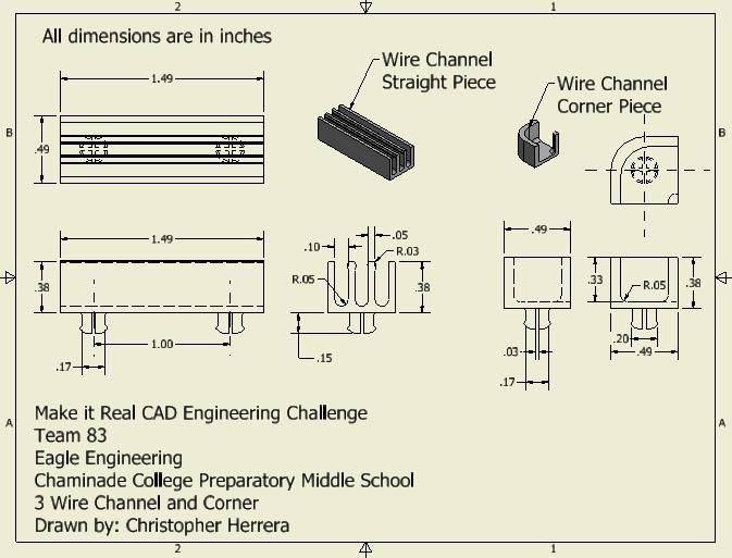
3 I am Christopher and I have designed a system of two parts to help with wire management. I created these parts to solve the issue of wire management. I am a programmer, so wire management is very important if I want to make sure that I have assigned the right sensors to the right ports. These parts help to achieve this by providing an easy way to trace wires and cleanly stack and remove individual wires. They are an improvement over zip ties and rubber bands because they are easy to work with and are reusable.
4 These parts will be used to: organize wires. help trace wires easily. prevent rat nests. These parts fits into the overall design of the robot by: snapping easily into the metal vex pattern. using its modular design to create any wire path. being relatively small and also light.

5 Inventor was used to make a 3D model of the parts. To make the model, first a simple 2D sketch of a rectangle was made and then expanded into a 3D rectangular prism. Then more rectangles were drawn on top of the box and the same feature was used to cut into it, forming the channels. The snap on piece was made by extruding, or as the process was called above, expanding, a circle outward and cutting a cross into it. The corner piece was made by cutting into a cube and rounding the edges.


6 With only two pieces any wire path can be configured. Isometric View of several straight sections and corner pieces A top view of the wire channel and the corner pieces. The wire channel snaps easily onto the Vex metal pattern.
7


8 Wire channels on a metal plate. Wire channels snap om easily. Straight piece Corner piece Snap on


9 Many different arrangements can be made. The pieces can be used in vertical orientation. The wire channels can even be taken completely off of the metal as a harness.
10 What did you learn from this project? Simple projects are more likely to succeed than large, complex projects that are poorly planned. Will you use Inventor in the future? If so, what for? I most likely will use Inventor in the future. I plan on joining robotics in high school, so I will have to use inventor to model parts for my team in the future. How does Inventor help you if you are on a competitive robotics team? Inventor helps to simulate future changes to our robot and test them, such as how hard it would be to make the changes and how much time it would take. Will learning 3D design software help you in your career path? If so, how? Learning 3D design software will help because, with 3D printing technology advancing, there will be more of a demand for 3D models that can be used to make physical parts. I might go into a career where this is important, in which case it will be important to know this skill. In fact, learning 3D design software has already helped me: my dad has access to 3D printers, and I used Inventor to make some pieces for a 7 th grade project.
11 I plan on designing some sort of cap that keeps wires in place. One improvement would be to find a way to fit the wire connectors in the channel. Since they are wider than the wires, they don t currently fit.
VEX IQ Challenge - Highrise. Field Appendix. Page 1. Copyright VEX Robotics Inc. v
 Field Appendix Page 1 Introduction This document will provide detailed specifications, a bill of materials (BOM), and assembly instructions for the Official Competition Field. Please note that this field
This document will provide detailed specifications and a bill of materials (BOM) for the Official Competition Field.
 for the Official Competition Field.") Introduction This document will provide detailed specifications and a bill of materials (BOM) for the Official Competition Field. Please note that this field utilizes the VEX IQ Challenge Full Field Perimeter
Introduction This document will provide detailed specifications and a bill of materials (BOM) for the Official Competition Field. Please note that this field utilizes the VEX IQ Challenge Full Field Perimeter
Shapes and Patterns. Lesson 1 Exploring Plane Shapes (Part 1) Name the shapes. triangle circle rectangle square Color the squares.
 Name the shapes. triangle circle rectangle square Color the squares.") CHAPTER 5 Shapes and Patterns Lesson 1 Exploring Plane Shapes (Part 1) Name the shapes. triangle circle rectangle square 1. 2. 3. 4. Color the squares. 5. Extra Practice 1A 71 Color the shapes that are
CHAPTER 5 Shapes and Patterns Lesson 1 Exploring Plane Shapes (Part 1) Name the shapes. triangle circle rectangle square 1. 2. 3. 4. Color the squares. 5. Extra Practice 1A 71 Color the shapes that are
When you complete this assignment you will:
 Objjectiives When you complete this assignment you will: 1. Set-up menus and drawing for designing modeling problems. 2. become familiar with the Sketch menu tools and commands. 3. Produce a three-dimensional
Shapes and Patterns. Practice 1 Exploring Plane Shapes. Trace the dots. Then match each shape to its name. 1. triangle. square. rectangle.
 CHAPTER 5 Shapes and Patterns Practice 1 Exploring Plane Shapes Trace the dots. Then match each shape to its name. 1. triangle square rectangle circle Lesson 1 Exploring Plane Shapes 93 A part of each
Cube in a cube Fusion 360 tutorial
 Cube in a cube Fusion 360 tutorial n Before using these instructions, it is helpful to watch this video screencast of the CAD drawing actually being done in the software. Click to link to the video tutorial.
Horizon - The horizontal line that contains the vanishing point(s) in a perspective drawing.
 in a perspective drawing.") Representing Solids Perspective Drawing A drawing where non-vertical parallel lines appear to meet at a point called a vanishing point. Example: If you look straight down a highway, it appears that the
Representing Solids Perspective Drawing A drawing where non-vertical parallel lines appear to meet at a point called a vanishing point. Example: If you look straight down a highway, it appears that the
Cross Sections of Three-Dimensional Figures
 Domain 4 Lesson 22 Cross Sections of Three-Dimensional Figures Common Core Standard: 7.G.3 Getting the Idea A three-dimensional figure (also called a solid figure) has length, width, and height. It is
DEPARTMENT OF MECHANICAL AND INDUSTRIAL ENGINEERING NORTHEASTERN UNIVERSITY
 DEPARTMENT OF MECHANICAL AND INDUSTRIAL ENGINEERING NORTHEASTERN UNIVERSITY CAPSULE PROGRAM Funded by NSF grant #0833636 Tutorial 02 3D Part Modeling SolidWorks 2010 Copyright 2010 Prof. Zeid 3D Part Modeling
Van Assembly. Creating an Assembly. Original by Steven Jaffe Modified by E. Brunelle 2/07 1
 Van Assembly Creating an Assembly 1 Part One the Axle 1. Set Units to Inches 2. Create a New Design. 3. Save the Design as axleinl_cad1_1 in your Van folder. 4. Create a New Sketch on the Lateral workplane.
Autodesk Inventor 2016 Creating Sketches
 Autodesk Inventor 2016 Creating Sketches 2D Sketch Practice 1 1. Launch Autodesk Inventor 2016 2. Create a new Part file (.ipt) 3. Save File As a. Click on the save icon. b. Save you file onto your flash
Engineering & Computer Graphics Workbook Using SolidWorks 2014
 Engineering & Computer Graphics Workbook Using SolidWorks 2014 Ronald E. Barr Thomas J. Krueger Davor Juricic SDC PUBLICATIONS Better Textbooks. Lower Prices. www.sdcpublications.com Powered by TCPDF (www.tcpdf.org)
Engineering & Computer Graphics Workbook Using SOLIDWORKS
 Engineering & Computer Graphics Workbook Using SOLIDWORKS 2017 Ronald E. Barr Thomas J. Krueger Davor Juricic SDC PUBLICATIONS Better Textbooks. Lower Prices. www.sdcpublications.com Powered by TCPDF (www.tcpdf.org)
GPLMS Revision Programme GRADE 3 Booklet
 GPLMS Revision Programme GRADE 3 Booklet Learner s name: School name: _ Day 1 1. Read carefully: a) The place or position of a digit in a number gives the value of that digit. b) In the number 273, 2,
Building Shapes. Geometry. Objective. Common Core State Standards Talk About It. Solve It. More Ideas. Formative Assessment
 2 Objective Building Shapes Giving children the opportunity to combine and take apart shapes helps them build several important mathematical skills. Such activities foster spatial reasoning and spatial
CADD I. A1 A2. I can recall from my notebook all course content and grading procedure. A3. I can list 3 ways Cadd impacts industry. B.
 St. Michael Albertville High School Teacher: Scott Danielson CADD I September 2016 CADD 1 Content Skills Learning Targets Standards Assessment Resources & Technology CEQ: WHAT AND HOW IS COMPUTER AIDED
We can sort objects in lots of different ways. How do you think we have sorted these shapes? Can you think of another way we could sort them?
 2D space sorting We can sort objects in lots of different ways. How do you think we have sorted these shapes? Can you think of another way we could sort them? Answers 1 Cut out these children and look
SKILL BUILDING. Learn techniques helpful in building prototypes. Introduction 02 Prototyping. Lesson plans 03 Prototyping skills
 SKILL BUILDING Learn techniques helpful in building prototypes. Introduction 02 Prototyping Lesson plans 03 Prototyping skills Resources 11 Skills stations Introduction 2 DID YOU KNOW? Prototyping is the
Unit-5 ISOMETRIC PROJECTION
 Unit-5 ISOMETRIC PROJECTION Importance Points in Isometric: 1. For drawing the isometric, the object must be viewed such that either the front -right or the left edges becomes nearest. 2. All vertical
Autodesk Inventor. In Engineering Design & Drafting. By Edward Locke
 Autodesk Inventor In Engineering Design & Drafting By Edward Locke Engineering Design Drafting Essentials Working Drawings: Orthographic Projection Views (multi-view, auxiliary view, details and sections)
Using Google SketchUp
 Using Google SketchUp Opening sketchup 1. From the program menu click on the SketchUp 8 folder and select 3. From the Template Selection select Architectural Design Millimeters. 2. The Welcome to SketchUp
VEX ROBOTICS ONLINE CHALLENGE:
 VEX ROBOTICS ONLINE CHALLENGE: MAKE IT REAL CAD ENGINEERING CHALLENGE By: SPONSORED BY AUTODESK SunCreated Woo Park Grade: 8th Team: 6446B 1 Table of Contents Cover Page 1 Table of Contents..2 Idea -Problem
SHAPE level 2 questions. 1. Match each shape to its name. One is done for you. 1 mark. International School of Madrid 1
 SHAPE level 2 questions 1. Match each shape to its name. One is done for you. International School of Madrid 1 2. Write each word in the correct box. faces edges vertices 3. Here is half of a symmetrical
Spatula. Spatula SW 2015 Design & Communication Graphics Page 1
 Spatula Introduction: The model shown in the picture is made of three parts, - the base, the washer and the handle. The base requires the use of Spline and Style Spline command, Slot command and Mirror
Inventor-Parts-Tutorial By: Dor Ashur
 Inventor-Parts-Tutorial By: Dor Ashur For Assignment: http://www.maelabs.ucsd.edu/mae3/assignments/cad/inventor_parts.pdf Open Autodesk Inventor: Start-> All Programs -> Autodesk -> Autodesk Inventor 2010
Second Semester Session Shri Ramdeobaba College of Engineering & Management, Nagpur. Department of Mechanical Engineering
 Second Semester Session- 2017-18 Shri Ramdeobaba College of Engineering & Management, Nagpur. Department of Mechanical Engineering Engineering Drawing Practical Problem Sheet Sheet No.:- 1. Scales and
Oblique Surfaces. Obl-1. Surface A is cut at an angle to all three reference planes. It will appear foreshortened in all the regular views.
 Oblique Surfaces Compound ngle Surfaces Oblique Surfaces in 3D Space Dimensioning Oblique Surfaces Modeling Oblique Surfaces ase Object Create Reference Plane Defining Object-Extents Oblique CutOut Special
Copyright 2013 A+ Interactive MATH (an A+ TutorSoft Inc. company), All Rights Reserved.
, All Rights Reserved.") www.aplustutorsoft.com Page 1 of 17 Introduction to Geometry Lesson, Worksheet & Solution Guide Release 7 A+ Interactive Math (By A+ TutorSoft, Inc.) Email: info@aplustutorsoft.com www.aplustutorsoft.com
www.aplustutorsoft.com Page 1 of 17 Introduction to Geometry Lesson, Worksheet & Solution Guide Release 7 A+ Interactive Math (By A+ TutorSoft, Inc.) Email: info@aplustutorsoft.com www.aplustutorsoft.com
Student Book SERIES. Space and Shape. Name
 Student ook Space and Shape Name Contents Series Space and Shape Topic 1 2D space (pp. 1 18) l sorting l squares and rectangles l circles and ovals l triangles l sides and corners l pentagons and hexagons
Straw support Fusion 360
 Straw support Fusion 360 Before using these instructions, watch the video screencast of the CAD drawing actually being done in the software. Click this link for video tutorial This design works on a variety
Solid Part Four A Bracket Made by Mirroring
 C h a p t e r 5 Solid Part Four A Bracket Made by Mirroring This chapter will cover the following to World Class standards: Sketch of a Solid Problem Draw a Series of Lines Finish the 2D Sketch Extrude
Understand Plane Sections of Prisms and Pyramids
 Lesson 25 Understand Plane Sections of Prisms and Pyramids Name: Prerequisite: How do you identify shapes according to their properties? Study the example showing how to identify shapes by using their
GPLMS Revision Programme GRADE 4 Booklet
 GPLMS Revision Programme GRADE 4 Booklet Learner s name: School name: Day 1. 1. Read carefully: a) The place or position of a digit in a number gives the value of that digit. b) In the number 4237, 4,
Pull Down Menu View Toolbar Design Toolbar
 Pro/DESKTOP Interface The instructions in this tutorial refer to the Pro/DESKTOP interface and toolbars. The illustration below describes the main elements of the graphical interface and toolbars. Pull
Introduction to Autodesk Inventor User Interface Student Manual MODEL WINDOW
 Emmett Wemp EDTECH 503 Introduction to Autodesk Inventor User Interface Fill in the blanks of the different tools available in the user interface of Autodesk Inventor as your instructor discusses them.
Assignment 12 CAD Mechanical Part 2
 Assignment 12 CAD Mechanical Part 2 Objectives In this assignment you will learn to apply the hidden lines, isometric snap, and ellipses commands along with commands previously learned.. General Hidden
NCERT Solutions Class 7 Mathematics Visualising Solid Shapes Chapter: 15
 Q.1) Exercise 15.1 NCERT Solutions Class 7 Mathematics Visualising Solid Shapes Chapter: 15 Identify the nets which can be used to make cubes (cut out copies of the nets and try it): Q.2) Sol.2) Cube s
When you complete this assignment you will:
 Objjectiives When you complete this assignment you will: 1. sketch and dimension circles and arcs. 2. cut holes in the model using the cut feature of the extrusion command. 3. create Arcs using the trim
BUILDING A VR VIEWER COMPLETE BUILD ASSEMBLY
 ACTIVITY 22: PAGE 1 ACTIVITY 22 BUILDING A VR VIEWER COMPLETE BUILD ASSEMBLY MATERIALS NEEDED One Rectangular Cardboard piece from 12-pack soda case Two round bi-convex lenses with a focal point of 45mm
CAD tutorial for the drinking straw support
 CAD tutorial for the drinking straw support Having tried a number of different designs, this one worked best on the greatest variety of glasses straight sided glass, angled glass and even a champagne flute.
Introduction to 3D Printing. Activity 1: Design a keychain using computer-aided design software
 Introduction to 3D Printing Activity 1: Design a keychain using computer-aided design software 1 In this activity we ll design a keychain name tag and learn the fundamentals of computer-aided design, the
2809 CAD TRAINING: Part 1 Sketching and Making 3D Parts. Contents
 Contents Getting Started... 2 Lesson 1:... 3 Lesson 2:... 13 Lesson 3:... 19 Lesson 4:... 23 Lesson 5:... 25 Final Project:... 28 Getting Started Get Autodesk Inventor Go to http://students.autodesk.com/
NAME: PERIOD: Perspective Packet (Week One)
") NAME: PERIOD: Perspective Packet (Week One) The following are your beginning assignments for perspective. You are to complete ONE page at a time. When you finish each page show it to me to sign off and
NAME: PERIOD: Perspective Packet (Week One) The following are your beginning assignments for perspective. You are to complete ONE page at a time. When you finish each page show it to me to sign off and
Getting Started Guide
 SOLIDWORKS Getting Started Guide SOLIDWORKS Electrical FIRST Robotics Edition Alexander Ouellet 1/2/2015 Table of Contents INTRODUCTION... 1 What is SOLIDWORKS Electrical?... Error! Bookmark not defined.
APJ ABDUL KALAM TECHNOLOGICAL UNIVERSITY SECOND SEMESTER B.TECH DEGREE EXAMINATION, MAY PART A Answer ANY Two questions. 10 marks each.
 B B2B111 Pages: 2 Reg. No. Name: SECOND SEMESTER B.TECH DEGREE EXAMINATION, MAY 2017 Max.Marks:50 Course Code: BE110 Duration:3Hours Answer ANY Two questions. 10 marks each. 1. A line AB 100 mm long and
How to build a Paper Marionette
 How to build a Paper Marionette 1) Find the pieces HA (head A) and HB (head B). a. Pop the holes out of HA and HB on one of the square sides and on the tab. b. Fold the 4 squares up to form an open ended
GPLMS Revision Programme GRADE 6 Booklet
 GPLMS Revision Programme GRADE 6 Booklet Learner s name: School name: Day 1. 1. a) Study: 6 units 6 tens 6 hundreds 6 thousands 6 ten-thousands 6 hundredthousands HTh T Th Th H T U 6 6 0 6 0 0 6 0 0 0
STUDY SET 03 ENGINEERING GEOMETRY
 STUDY SET 03 ENGINEERING GEOMETRY PROBLEMS FOR LABORATORY WORK 3.1 Coordinate Exercise 1 Draw the shape using the coordinate values. 3.2 Coordinate Exercise 2 Draw the shape with the given dimensions.
Introduction to ANSYS DesignModeler
 Lecture 4 Planes and Sketches 14. 5 Release Introduction to ANSYS DesignModeler 2012 ANSYS, Inc. November 20, 2012 1 Release 14.5 Preprocessing Workflow Geometry Creation OR Geometry Import Geometry Operations
Welcome to the a Department of Engineering Education! ENGR 1182 Introduction to Engineering II Graphics 01
 Welcome to the a Department of Engineering Education! ENGR 1182 Introduction to Engineering II Graphics 01 Today s Objectives Teaching Team Introduction Course Structure & Expectations Course Syllabus
The project focuses on the design for a Pencil holder, but could be adapted to any simple assembly.
 Introduction - Teacher Notes Fig 1. The project focuses on the design for a Pencil holder, but could be adapted to any simple assembly. Pro/DESKTOP enables pupils (and teachers) to communicate and model
1. Choose two shapes. Combine the shapes to make a new shape. Make sure that the two shapes share a side. Draw your new shape.
 Name Unit 7 Shape Up!. Choose two shapes. Combine the shapes to make a new shape. Make sure that the two shapes share a side. Draw your new shape. 2. Describe each shape you used. Explain how your new
Starting a 3D Modeling Part File
 1 How to Create a 3D Model and Corresponding 2D Drawing with Dimensions, GDT (Geometric Dimensioning and Tolerance) Symbols and Title Block in SolidWorks 2013-2014 By Edward Locke This tutorial will introduce
DEPARTMENT OF MECHANICAL ENGINEERING, IIT DELHI
 MEL 110 LABORATORY 1 (to be done in CAGI Lab. Room: III 331) DURATION: 3 Hrs 50 Min. Note: Missing dimensions may be suitably assumed. Exercise 1: Visualize orthographic and isometric views of 3D models/objects:
Geometry. Learning Goals U N I T
 U N I T Geometry Building Castles Learning Goals describe, name, and sort prisms construct prisms from their nets construct models of prisms identify, create, and sort symmetrical and non-symmetrical shapes
1. If one side of a regular hexagon is 2 inches, what is the perimeter of the hexagon?
 Geometry Grade 4 1. If one side of a regular hexagon is 2 inches, what is the perimeter of the hexagon? 2. If your room is twelve feet wide and twenty feet long, what is the perimeter of your room? 3.
Investigation Optimization of Perimeter, Area, and Volume Activity #1 Minimum Perimeter
 Investigation Optimization of Perimeter, Area, and Volume Activity #1 Minimum Perimeter 1. Choose a bag from the table and record the number from the card in the space below. Each member of your group
How to Draw with a Grid
 Level: Beginner Flesch-Kincaid Grade Level: 8.3 Flesch-Kincaid Reading Ease: 67.5-6 Pages and 12 Illustrations How to Draw with a Grid Exploring the grid method to draw accurate outline drawings This resource
ENGINEERING GRAPHICS
 ENGINEERING GRAPHICS CLASS - XII (046) DESIGN OF THE QUESTION PAPER Time : 3 Hrs Max. Marks : 70 The weightage of the distribution of marks over different contents of the question paper shall be as follows:
Middle School Geometry. Session 2
 Middle School Geometry Session 2 Topic Activity Name Page Number Related SOL Spatial Square It 52 6.10, 6.13, Relationships 7.7, 8.11 Tangrams Soma Cubes Activity Sheets Square It Pick Up the Toothpicks
ONE-POINT PERSPECTIVE
 NAME: PERIOD: PERSPECTIVE Linear Perspective Linear Perspective is a technique for representing 3-dimensional space on a 2- dimensional (paper) surface. This method was invented during the Renaissance
First Practice Test 2 Levels 3-5 Calculator allowed
 Mathematics First Practice Test 2 Levels 3-5 Calculator allowed First name Last name School Remember The test is 1 hour long. You may use a calculator for any question in this test. You will need: pen,
Eureka Math. Grade K, Module 2. Student File_A. Contains copy-ready classwork and homework as well as templates (including cut outs)
") A Story of Units Eureka Math Grade K, Module 2 Student File_A Contains copy-ready classwork and homework as well as templates (including cut outs) Published by the non-profit Great Minds. Copyright 2015
A Story of Units Eureka Math Grade K, Module 2 Student File_A Contains copy-ready classwork and homework as well as templates (including cut outs) Published by the non-profit Great Minds. Copyright 2015
Name: Date Completed: Basic Inventor Skills I
 Name: Date Completed: Basic Inventor Skills I 1. Sketch, dimension and extrude a basic shape i. Select New tab from toolbar. ii. Select Standard.ipt from dialogue box by double clicking on the icon. iii.
COURSE: INTRODUCTION TO CAD GRADES: UNIT: Measurement
 UNIT: Measurement - Students will demonstrate correctness in measuring using various scales and instruments. Demonstrate the various marks that make up a ruler including 1/16, 1/8, ¼ and ½. Assessment
Work Experience Pack. Prepared by LMP Architectural Consultants. LMP Architectural Consultants Work Experience Pack
 Prepared by 1 1.0 Exercise 1 Freehand Trace In this exercise you will learn the basics of using a traditional drawing board, technical pens and the set square. You will require the following materials
Diane Burton, STEM Outreach.
 123D Design Tutorial: LED decoration Before using these instructions, it is very helpful to watch this video screencast of the CAD drawing actually being done in the software. Click this link for the video
Module 2: Radial-Line Sheet-Metal 3D Modeling and 2D Pattern Development: Right Cone (Regular, Frustum, and Truncated)
") Inventor (5) Module 2: 2-1 Module 2: Radial-Line Sheet-Metal 3D Modeling and 2D Pattern Development: Right Cone (Regular, Frustum, and Truncated) In this tutorial, we will learn how to build a 3D model
Inventor (5) Module 2: 2-1 Module 2: Radial-Line Sheet-Metal 3D Modeling and 2D Pattern Development: Right Cone (Regular, Frustum, and Truncated) In this tutorial, we will learn how to build a 3D model
Standards Based Report Card Rubrics
 Grade Level: Kindergarten Standards Based Report Card Rubrics Content Area: Math Standard/Strand: MA.K.CCSS.Math.Content.K.CC.A.1 Count to 100 by ones and by tens. count to 100 by ones and/or tens with
ISOMETRIC PROJECTION. Contents. Isometric Scale. Construction of Isometric Scale. Methods to draw isometric projections/isometric views
 ISOMETRIC PROJECTION Contents Introduction Principle of Isometric Projection Isometric Scale Construction of Isometric Scale Isometric View (Isometric Drawings) Methods to draw isometric projections/isometric
Part I Introduction to CorelCAD
 Table of Contents Part I Introduction to CorelCAD 1 Introducing CorelCAD for Mac... 3 About CorelCAD... 3 Benefits of Using CorelCAD....4 Impressive Compatibility... 4 Familiar User Interface.... 4 Drafting
Symmetrical Figures. Geometry. Objective. Common Core State Standards Talk About It. Solve It. More Ideas. Formative Assessment
 5 Objective Symmetrical Figures In this lesson, students solve problems involving symmetry. Because relationships across a line of symmetry correspond exactly in terms of size, form, and arrangement, students
 (Chapter 15) (Visualising Solid Shapes) (Class VII) Question 1: Exercise 15.1 Identify the nets which can be used to make cubes (cut out copies of the nets and try it): Answer 1: Cube s nets are (ii),
Top Down Assembly Modeling Release Wildfire 2.0
 Top Down Assembly Modeling Release Wildfire 2.0 Note: Comprehensive Modeling Assignment This is a 30 point assignment as such takes the place of the final exam. Four Plate Mold Base, Inner Two Plates Begin
Op Art Pinwheel Side 1 Choices
 Op Art Pinwheel Side 1 Choices 1. 1) Draw an X from corner to corner. Then draw a vertical line and horizontal line that match up in the center. 2) draw curved lines, spaced about 1/2" apart, between the
SIDDHARTH GROUP OF INSTITUTIONS :: PUTTUR
 SIDDHARTH GROUP OF INSTITUTIONS :: PUTTUR Siddharth Nagar, Narayanavanam Road 517583 QUESTION BANK Subject Code : Engineering Graphics& Design Course & Branch : B.Tech ALL Year & Sem : I B.Tech & I Sem
Activity 5.2 Making Sketches in CAD
 Activity 5.2 Making Sketches in CAD Introduction It would be great if computer systems were advanced enough to take a mental image of an object, such as the thought of a sports car, and instantly generate
R2-D2 SolidWorks Model
 R2-D2 SolidWorks Model Mike Haftl E-Design 100 Section 7 August 5, 2016 Haftl 1 Rendered Images Figure 1: Front view of R2-D2 model made in solid works Figure 2: Isometric Left view of R2-D2 model made
INSTITUTE OF AERONAUTICAL ENGINEERING
 Course Name Course Code Class Branch INSTITUTE OF AERONAUTICAL ENGINEERING Dundigal, Hyderabad - 500 043 MECHANICAL ENGINEERING TUTORIAL QUESTION BANK : ENGINEERING DRAWING : A10301 : I - B. Tech : Common
Problem of the Month: Between the Lines
 Problem of the Month: Between the Lines Overview: In the Problem of the Month Between the Lines, students use polygons to solve problems involving area. The mathematical topics that underlie this POM are
Module 1H: Creating an Ellipse-Based Cylindrical Sheet-metal Lateral Piece
 Inventor (10) Module 1H: 1H- 1 Module 1H: Creating an Ellipse-Based Cylindrical Sheet-metal Lateral Piece In this Module, we will learn how to create an ellipse-based cylindrical sheetmetal lateral piece
Introduction to Programming. June 4 June 8, and July 9 July 13 Mo-Fr., 8:30AM - 3:30PM
 Introduction to Programming June 4 June 8, and July 9 July 13 This hands-on training will teach basics of computer programming. Campers will learn how computers work, how to control devices and components
International Journal of Scientific & Engineering Research, Volume 7, Issue 11, November ISSN HEAT EXCHANGER.
 International Journal of Scientific & Engineering Research, Volume 7, Issue 11, November-2016 577 HEAT EXCHANGER Hassan Alshaiki Table of contents Introduction 3 Designing the Heat Exchanger..4 Base Nut
How to draw the CB South Kerf Bent Clock:
 How to draw the CB South Kerf Bent Clock: Open sketch up, use the Product Design and Woodworking template with Inches as the units. If there is a person in the drawing space, you can delete him/her. When
Understanding Projection Systems
 Understanding Projection Systems A Point: A point has no dimensions, a theoretical location that has neither length, width nor height. A point shows an exact location in space. It is important to understand
Tools for Design. with VEX Robot Kit: Randy H. Shih Oregon Institute of Technology SDC PUBLICATIONS
 Tools for Design with VEX Robot Kit: AutoCAD 2011 and Autodesk Inventor 2011 2D Drawing 3D Modeling Hand Sketching Randy H. Shih Oregon Institute of Technology INSIDE: SUPPLEMENTAL FILES ON CD SDC PUBLICATIONS
TOY TRUCK. Figure 1. Orthographic projections of project.
 TOY TRUCK Prepared by: Harry Hawkins The following project is of a small, wooden toy truck. This exercise will provide you with the procedure for constructing the various parts of the design then assembling
Term 3. Explanations of assignments
 Term 3 Explanations of assignments (If you are in class, you would get more detailed explanation with powerpoints, demonstrations, examples and other methods of learning.) Categories: Assignments are in
Released Assessment Questions, 2018 ANSWERS
 Released Assessment Questions, 218 ANSWERS Grade 9 Assessment of Mathematics Academic DIRECTIONS Answering Multiple-Choice Questions Answer all multiple-choice questions. If you fill in more than one answer
E11: Autonomous Vehicles. Lab 2: 3D CAD and Printing
 E11: Autonomous Vehicles Lab 2: 3D CAD and Printing The goal of this lab is to create a robot chassis in SolidWorks that can be printed on HMC s 3D printer. When you are done, the chassis should look like
The Grade 1 Common Core State Standards for Geometry specify that children should
 in the elementary classroom means more than recalling the names of shapes, measuring angles, and making tessellations it is closely linked to other mathematical concepts. For example, geometric representations
Drawing and Assembling
 Youth Explore Trades Skills Description In this activity the six sides of a die will be drawn and then assembled together. The intent is to understand how constraints are used to lock individual parts
ENGINEERING DRAWING. UNIT III - Part A
 DEVELOPMENT OF SURFACES: ENGINEERING DRAWING UNIT III - Part A 1. What is meant by development of surfaces? 2. Development of surfaces of an object is also known as flat pattern of the object. (True/ False)
Name. Geometry. ETA hand2mind
 Lesson 1 Geometry Name 1. 2. Directions 1. Color the triangle in the circle on the left side. Put an X on the rectangle in the circle on the right side. 2. Draw a triangle in the box on the right. Draw
SolidWorks Navigation
 SolidWorks Basics SolidWorks Navigation Command Bar Feature Tree Model Window Simple Box Select the Front plane Create a new sketch Create a Center Rectangle from the origin Smart Dimension the length
J. La Favre Fusion 360 Lesson 4 April 21, 2017
 In this lesson, you will create an I-beam like the one in the image to the left. As you become more experienced in using CAD software, you will learn that there is usually more than one way to make a 3-D
Robotics Links to ACARA
 MATHEMATICS Foundation Shape Sort, describe and name familiar two-dimensional shapes and three-dimensional objects in the environment. (ACMMG009) Sorting and describing squares, circles, triangles, rectangles,
2.000 Sketching Example: Tractor transmission
 1. HAVE A PLAN:Look at the transmission from the angle you want to draw it from choose an angle that will show the most information. Here we choose to draw an oblique sketch for clarity and simplicity.
ENGINEERING GRAPHICS UNIT V ISOMETRIC PROJECTION PERSPECTIVE PROJECTION
 ENGINEERING GRAPHICS UNIT V ISOMETRIC PROJECTION PERSPECTIVE PROJECTION 1.PICTORIAL PROJECTIONS To visualize the shape of the whole object in its 3- D form, all the two or three orthographic views of the
Module 1C: Adding Dovetail Seams to Curved Edges on A Flat Sheet-Metal Piece
 1 Module 1C: Adding Dovetail Seams to Curved Edges on A Flat Sheet-Metal Piece In this Module, we will explore the method of adding dovetail seams to curved edges such as the circumferential edge of a