Van Assembly. Creating an Assembly. Original by Steven Jaffe Modified by E. Brunelle 2/07 1
|
|
|
- Dwain Hubert Jenkins
- 5 years ago
- Views:
Transcription


1 Van Assembly Creating an Assembly 1

2 Part One the Axle 1. Set Units to Inches 2. Create a New Design. 3. Save the Design as axleinl_cad1_1 in your Van folder. 4. Create a New Sketch on the Lateral workplane. Name the sketch axle. 5. Shift-W to view onto workplane. 6. Using the Circle tool, drag out and dimension a 1 inch circle from the 0,0 point. DON T FORGET TO DIMENSION THE CIRCLE!! 2


3 7. Shift T to View Trimetric. Go to Features > Extrude profile. Add Material > Above Workplane >12 inches. 8. Shift-A to Autoscale. Your Axle should look like the one below. Save your work, then Close the Axle. Watch Video 3

4 Part Two the Wheel 1. Create a New Design. 2. Save the Design as wheelinl_cad1_1 in your Van folder. 3. Create a New Sketch on the Lateral workplane. Name the sketch wheel. 4. Shift-W to view onto workplane. 5. Using the Circle tool, drag out and dimension a 5 inch circle from the 0,0 point. DON T FORGET TO DIMENSION THE CIRCLE!! 4

5 6. Next, draw a concentric circle inside of the first circle. Concentric means that the two circles will use the same center point, 0,0 in this case. 5

![Select Edges or [E].](/docs-images/94/120839395/images/6-1.jpg "Select the two outside edges of the wheel by selecting one edge, holding Shift while selecting")
6 7. Shift-T to View Trimetric. 8. Go to Feature >Extrude profile. Add Material > Above Workplane > 1.5 INCHES. Be sure to name the extrusion extwheel: 9. Select Edges or [E]. Select the two outside edges of the wheel by selecting one edge, holding Shift while selecting the second edge. Right click >Round Edges to a radius of.25 inches. Watch Video 10. Save the wheel and close. 6

7 Part Three the Body 1. Create a New Design. 2. Save the Design as bodyinl_cad1_1 in your Van folder. 3. Create a New Sketch on the Lateral workplane. Name the sketch body. 4. Shift-W to view onto workplane. 5. Using the rectangle tool, drag out and dimension a 12 inch by 24 inch rectangle from the 0,0 point. DON T FORGET TO DIMENSION THE RECTANGLE!! 7


8 6. While still on the body sketch, drag out a circle in the bottom left corner. 7. Dimension the circle to a diameter of 1 inch. 8. Position the circle using the dimension tool so that it is 3 inches from the left vertical line and one inch from the bottom line. BE SURE TO DIMENSION FROM THE CENTER OF THE CIRCLE!! Watch Video 9. Create an identical hole positioned the same way on the right side. 8


9 10. Shift-T to view Trimetric. Shift- A to Autoscale. 11. Go to Feature > Extrude profile. Fill out the box like the one below: 12. Your van body should look like the one below: Watch Video 9


10 13. Save your body. 14. Select Edges and select the top front edge of the body. Right Click > Chamfer Edges. 15. Fill out the box like the one below. Notice you are creating an unequal setback. Be sure to name the feature chamferfront_edge. Watch Video 10


11 16. Your finished chamfer should look like the one below left: 17. Round all straight edges to a radius of 0.25 inches below right. Watch Video 18. Using techniques that you learned in the Toy Block assignment, Extrude your name as text on the side of the van body 19. Save your van body, then close. 11

12 Part Four - Assembling the Van 1. Create a New Design. Save the Design as "assembly_vaninl_cad1_1" in your Van folder NOTE: You MUST start a new design to do an assembly. 2. Go to Assembly > Add Component. 3. Click on your body design and then OK. 4. The two features you will use to assemble the components will be the Parts tool to move parts and the Faces tool to "glue" the pieces together. Use the Faces tool to assemble (glue) components Use the Parts tool to move a component 5. Use the Parts tool to select the body (it will be red). Then go to Assembly > Fix Component to prevent the van from moving during assembly. You can also Right Click > Fix Components Watch Video 12


13 6. Go to and get the Axle. 7. Use the Faces tool to click the axle cylinder and then hold Shift to click the inside of the axle hole in the van. 8. Go to Assembly > Center Axes and then click OK. Or Right Click > Center Axis. Use the Face tool. Select the cylindrical face of the axle, HOLD SHIFT, then select the cylindrical face of the axle hole. Right Click > Center Axis. 9. The axle will now be in the axle hole on the body. Watch Video 13


14 10. Select Assembly > Add Component and bring in a wheel. 11. Click in the axle hole of the wheel and Shift and click the axle cylinder. 12. Assembly > Center Axes, then OK to put the wheel on the axle. Watch Video Note: Your wheel may be "in" the body. Don't worry! Just use the Parts tool to select and drag the wheel out of the body. 13. Using the Parts tool, click and drag the axle so it sticks out through the wheel. 14. Now use the Face tool to select the end of the axle and the outside wall of the wheel. 15. Select Assembly > Align. The axle end and the outside wheel wall will be flush with each other. 14
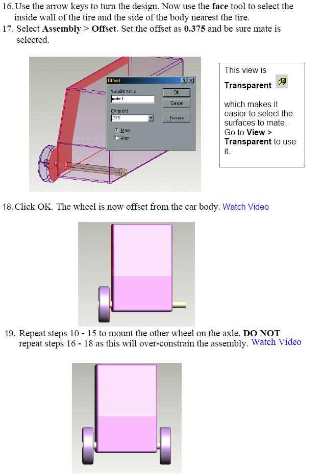
15 15

16 20. Now, repeat steps 6-18 to finish your assembly 21. File > Save your van assembly 16
17 17
18 18
Canoe Mirroring Lofts
 Canoe Mirroring Lofts 1. Set Units to Inches 2. Create a New Design. 3. Save the Design as canoeinl811 in your Canoe folder. 4. Create a New Sketch on the Frontal Workplane. Name the Sketch Middle. 5.
Pro/DESKTOP Tutorial Drafting Bow Compass
 Pro/DESKTOP Tutorial Drafting Bow Compass Michael Flowers 2005 1 Objectives: To develop confidence with the Pro/DESKTOP software. To learn to utilize extrude, project, revolve, round, and chamfer features.
Digital Camera Exercise
 Commands Used New Part This lesson includes Sketching, Extruded Boss/Base, Extruded Cut, Fillet, Chamfer and Text. Click File, New on the standard toolbar. Select Part from the New SolidWorks Document
The project focuses on the design for a Pencil holder, but could be adapted to any simple assembly.
 Introduction - Teacher Notes Fig 1. The project focuses on the design for a Pencil holder, but could be adapted to any simple assembly. Pro/DESKTOP enables pupils (and teachers) to communicate and model
EXERCISE ONE: BEACH BUGGY.
 EXERCISE ONE: BEACH BUGGY. Prerequisite knowledge Students should have completed Exercises from the file: Introduction to Assemblies Concept Mates Focus of lesson Commands Used This lesson will focus on
SolidWorks Navigation
 SolidWorks Basics SolidWorks Navigation Command Bar Feature Tree Model Window Simple Box Select the Front plane Create a new sketch Create a Center Rectangle from the origin Smart Dimension the length
Diane Burton, STEM Outreach.
 123D Design Tutorial: LED decoration Before using these instructions, it is very helpful to watch this video screencast of the CAD drawing actually being done in the software. Click this link for the video
Introduction to Autodesk Inventor User Interface Student Manual MODEL WINDOW
 Emmett Wemp EDTECH 503 Introduction to Autodesk Inventor User Interface Fill in the blanks of the different tools available in the user interface of Autodesk Inventor as your instructor discusses them.
Getting Started. Right click on Lateral Workplane. Left Click on New Sketch
 Getting Started 1. Open up PTC Pro/Desktop by either double clicking the icon or through the Start button and in Programs. 2. Once Pro/Desktop is open select File > New > Design 3. Close the Pallet window
Creo Revolve Tutorial
 Creo Revolve Tutorial Setup 1. Open Creo Parametric Note: Refer back to the Creo Extrude Tutorial for references and screen shots of the Creo layout 2. Set Working Directory a. From the Model Tree navigate
Shaft Hanger - SolidWorks
 ME-430 INTRODUCTION TO COMPUTER AIDED DESIGN Shaft Hanger - SolidWorks BY: DR. HERLI SURJANHATA ASSIGNMENT Submit TWO isometric views of the Shaft Hanger with your report, 1. Shaded view of the trimetric
Table of Contents. Lesson 1 Getting Started
 NX Lesson 1 Getting Started Pre-reqs/Technical Skills Basic computer use Expectations Read lesson material Implement steps in software while reading through lesson material Complete quiz on Blackboard
Creating Van Drawings
 Creating Van Drawings Engineers create Drawings that manufacturers (and assemblers) use to make products. You are going to create Drawings in ProDESKTOP much like real engineers would for a product like
TOY TRUCK. Figure 1. Orthographic projections of project.
 TOY TRUCK Prepared by: Harry Hawkins The following project is of a small, wooden toy truck. This exercise will provide you with the procedure for constructing the various parts of the design then assembling
DEPARTMENT OF MECHANICAL AND INDUSTRIAL ENGINEERING NORTHEASTERN UNIVERSITY
 DEPARTMENT OF MECHANICAL AND INDUSTRIAL ENGINEERING NORTHEASTERN UNIVERSITY CAPSULE PROGRAM Funded by NSF grant #0833636 Tutorial 02 3D Part Modeling SolidWorks 2010 Copyright 2010 Prof. Zeid 3D Part Modeling
The Revolve Feature and Assembly Modeling
 The Revolve Feature and Assembly Modeling PTC Clock Page 52 PTC Contents Introduction... 54 The Revolve Feature... 55 Creating a revolved feature...57 Creating face details... 58 Using Text... 61 Assembling
Cube in a cube Fusion 360 tutorial
 Cube in a cube Fusion 360 tutorial n Before using these instructions, it is helpful to watch this video screencast of the CAD drawing actually being done in the software. Click to link to the video tutorial.
Activity 5.5a CAD Model Features Part 1
 Activity 5.5a CAD Model Features Part 1 Introduction In order to use CAD effectively as a design tool, the designer must have the skills necessary to create, edit, and manipulate a 3D model of a part in
Name: Date Completed: Basic Inventor Skills I
 Name: Date Completed: Basic Inventor Skills I 1. Sketch, dimension and extrude a basic shape i. Select New tab from toolbar. ii. Select Standard.ipt from dialogue box by double clicking on the icon. iii.
Autodesk Inventor. In Engineering Design & Drafting. By Edward Locke
 Autodesk Inventor In Engineering Design & Drafting By Edward Locke Engineering Design Drafting Essentials Working Drawings: Orthographic Projection Views (multi-view, auxiliary view, details and sections)
When you complete this assignment you will:
 Objjectiives When you complete this assignment you will: 1. sketch and create models using new work planes and the loft command. 2. sketch and create models using the revolve command. 3. sketch and dimension
Straw support Fusion 360
 Straw support Fusion 360 Before using these instructions, watch the video screencast of the CAD drawing actually being done in the software. Click this link for video tutorial This design works on a variety
Solidworks: Lesson 4 Assembly Basics and Toolbox. UCF Engineering
 Solidworks: Lesson 4 Assembly Basics and Toolbox UCF Engineering Solidworks We have now completed the basic features of part modeling and it is now time to begin constructing more complex models in the
From the above fig. After sketching the path and profile select the sweep command First select the profile from property manager tree And then select
 Chapter 5 In sweep command there is a) Two sketch profiles b) Two path c) One sketch profile and one path The sweep profile is used to create threads springs circular things and difficult geometry. For
Engineering & Computer Graphics Workbook Using SolidWorks 2014
 Engineering & Computer Graphics Workbook Using SolidWorks 2014 Ronald E. Barr Thomas J. Krueger Davor Juricic SDC PUBLICATIONS Better Textbooks. Lower Prices. www.sdcpublications.com Powered by TCPDF (www.tcpdf.org)
Engineering Innovation Center Autodesk Fusion 360
 Engineering Innovation Center Autodesk Fusion 360 Introduction The Engineering Innovation Center is a large academic maker space with plenty of tools and equipment. In order to use these items you must
Engineering & Computer Graphics Workbook Using SOLIDWORKS
 Engineering & Computer Graphics Workbook Using SOLIDWORKS 2017 Ronald E. Barr Thomas J. Krueger Davor Juricic SDC PUBLICATIONS Better Textbooks. Lower Prices. www.sdcpublications.com Powered by TCPDF (www.tcpdf.org)
DUE DATE: Friday 4/6/2018 at 3:30 PM
 MECH 130 SPRING 2018 CAD LAB 4 FINAL REVISION HARDCOPIES NEEDED DUE DATE: Friday 4/6/2018 at 3:30 PM After the revised hitch, the ball and the pin parts were created from the Handout call LAB4 PART Creation,
g. Click once on the left vertical line of the rectangle.
 This drawing will require you to a model of a truck as a Solidworks Part. Please be sure to read the directions carefully before constructing the truck in Solidworks. Before submitting you will be required
1. Creating geometry based on sketches 2. Using sketch lines as reference 3. Using sketches to drive changes in geometry
 4.1: Modeling 3D Modeling is a key process of getting your ideas from a concept to a read- for- manufacture state, making it core foundation of the product development process. In Fusion 360, there are
Techniques for Troubleshooting Sketches &
 Techniques for Troubleshooting Sketches & Written by Tim Brotherhood These materials are 2001 PTC Conditions of use Copying and use of these materials is authorized only in the schools of teachers who
Lab 3 Introduction to SolidWorks I Silas Bernardoni 10/9/2008
 1 Introduction This lab is designed to provide you with basic skills when using the 3D modeling program SolidWorks. You will learn how to build parts, assemblies and drawings. You will be given a physical
Pull Down Menu View Toolbar Design Toolbar
 Pro/DESKTOP Interface The instructions in this tutorial refer to the Pro/DESKTOP interface and toolbars. The illustration below describes the main elements of the graphical interface and toolbars. Pull
AEROPLANE. Create a New Folder in your chosen location called Aeroplane. The four parts that make up the project will be saved here.
 AEROPLANE Prerequisite Knowledge Previous knowledge of the following commands is required to complete this lesson. Sketching (Line, Rectangle, Arc, Add Relations, Dimensioning), Extrude, Assemblies and
Lesson 4 Holes and Rounds
 Lesson 4 Holes and Rounds 111 Figure 4.1 Breaker OBJECTIVES Sketch arcs in sections Create a straight hole through a part Complete a Sketched hole Understand the Hole Tool Use Info to extract information
Bottom Rail. Chapter 2. Chair. A. Weldments Toolbar. Step 1. Click File Menu > New, click Part and OK. B. 3D Sketch.
 Chapter 2 Chair Bottom Rail A. Weldments Toolbar. Step 1. Click File Menu > New, click Part and OK. Step 2. Right click Sketch on the Command Manager toolbar and select Weldments, Fig. 1. Step 3. Click
Starting a 3D Modeling Part File
 1 How to Create a 3D Model and Corresponding 2D Drawing with Dimensions, GDT (Geometric Dimensioning and Tolerance) Symbols and Title Block in SolidWorks 2013-2014 By Edward Locke This tutorial will introduce
SolidWorks Tutorial 1. Axis
 SolidWorks Tutorial 1 Axis Axis This first exercise provides an introduction to SolidWorks software. First, we will design and draw a simple part: an axis with different diameters. You will learn how to
Introduction to Circular Pattern Flower Pot
 Prerequisite Knowledge Previous knowledge of the sketching commands Line, Circle, Add Relations, Smart Dimension is required to complete this lesson. Previous examples of Revolved Boss/Base, Cut Extrude,
Introduction to Revolve - A Glass
 Introduction to Revolve - A Glass Design & Communication Graphics 1 Object Analysis sheet Design & Communication Graphics 2 Prerequisite Knowledge Previous knowledge of the following commands are required
SolidWorks Part I - Basic Tools SDC. Includes. Parts, Assemblies and Drawings. Paul Tran CSWE, CSWI
 SolidWorks 2015 Part I - Basic Tools Includes CSWA Preparation Material Parts, Assemblies and Drawings Paul Tran CSWE, CSWI SDC PUBLICATIONS Better Textbooks. Lower Prices. www.sdcpublications.com Powered
Part 8: The Front Cover
 Part 8: The Front Cover 4 Earpiece cuts and housing Lens cut and housing Microphone cut and housing The front cover is similar to the back cover in that it is a shelled protrusion with screw posts extruding
SolidWorks Design & Technology
 SolidWorks Design & Technology Training Course at PHSG Ex 5. Lego man Working with part files 8mm At first glance the Lego man looks complicated but I hope you will see that if you approach a project one
Assembly Receiver/Hitch/Ball/Pin to use for CAD LAB 5A and 5B:
 MECH 130 CAD LAB 5 SPRING 2017 due Friday, April 21, 2016 at 4:30 PM All of LAB 5 s hardcopies will be working drawing layouts. Do not print out from the part file. We will be using the ME130DRAW drawing
Chair. Bottom Rail. on the Command Manager. on the Weldments toolbar.
 Chapter 2 Chair Bottom Rail A. Weldments Toolbar. Step 1. Click File Menu > New, click Part and OK. Step 2. Right click Sketch on the Command Manager toolbar and select Weldments, Fig. 1. Step 3. Click
Autodesk Inventor 2016 Creating Sketches
 Autodesk Inventor 2016 Creating Sketches 2D Sketch Practice 1 1. Launch Autodesk Inventor 2016 2. Create a new Part file (.ipt) 3. Save File As a. Click on the save icon. b. Save you file onto your flash
Siemens NX11 tutorials. The angled part
 Siemens NX11 tutorials The angled part Adaptation to NX 11 from notes from a seminar Drive-to-trial organized by IBM and GDTech. This tutorial will help you design the mechanical presented in the figure
Modeling Basic Mechanical Components #1 Tie-Wrap Clip
 Modeling Basic Mechanical Components #1 Tie-Wrap Clip This tutorial is about modeling simple and basic mechanical components with 3D Mechanical CAD programs, specifically one called Alibre Xpress, a freely
Solid Part Four A Bracket Made by Mirroring
 C h a p t e r 5 Solid Part Four A Bracket Made by Mirroring This chapter will cover the following to World Class standards: Sketch of a Solid Problem Draw a Series of Lines Finish the 2D Sketch Extrude
Rotational Patterns of Sketched Features Using Datum Planes On-The-Fly
 Rotational Patterns of Sketched Features Using Datum Planes On-The-Fly Patterning a sketched feature (such as a slot, rib, square, etc.,) requires a slightly different technique. Why can t we create a
Activity Pegboard Toy
 Activity 1.5.5 Pegboard Toy Purpose When you receive a toy, what is the first thing you wonder about it? Do you wonder how it works? Have you ever wondered who designed it or who may have made decisions
Lesson 6 2D Sketch Panel Tools
 Lesson 6 2D Sketch Panel Tools Inventor s Sketch Tool Bar contains tools for creating the basic geometry to create features and parts. On the surface, the Geometry tools look fairly standard: line, circle,
When you complete this assignment you will:
 Objjectiives When you complete this assignment you will: 1. sketch and dimension circles and arcs. 2. cut holes in the model using the cut feature of the extrusion command. 3. create Arcs using the trim
2.000 Sketching Example: Tractor transmission
 1. HAVE A PLAN:Look at the transmission from the angle you want to draw it from choose an angle that will show the most information. Here we choose to draw an oblique sketch for clarity and simplicity.
Part 2: Earpiece. Insert Protrusion (Internal Sketch) Hole Patterns Getting Started with Pro/ENGINEER Wildfire. Round extrusion.
 Hole Patterns Getting Started with Pro/ENGINEER Wildfire. Round extrusion.") Part 2: Earpiece 4 Round extrusion Radial pattern Chamfered edge To create this part, you'll use some of the same extrusion techniques you used in the lens part. The only difference in this part is that
Part 2: Earpiece 4 Round extrusion Radial pattern Chamfered edge To create this part, you'll use some of the same extrusion techniques you used in the lens part. The only difference in this part is that
Create A Mug. Skills Learned. Settings Sketching 3-D Features. Revolve Offset Plane Sweep Fillet Decal* Offset Arc
 Create A Mug Skills Learned Settings Sketching 3-D Features Slice Line Tool Offset Arc Revolve Offset Plane Sweep Fillet Decal* Tutorial: Creating A Custom Mug There are somethings in this world that have
Module 1G: Creating a Circle-Based Cylindrical Sheet-metal Lateral Piece with an Overlaying Lateral Edge Seam And Dove-Tail Seams on the Top Edge
 Inventor (10) Module 1G: 1G- 1 Module 1G: Creating a Circle-Based Cylindrical Sheet-metal Lateral Piece with an Overlaying Lateral Edge Seam And Dove-Tail Seams on the Top Edge In Module 1A, we have explored
Activity Pegboard Toy
 Activity 1.5.5 Pegboard Toy Purpose When you receive a toy, what is the first thing you wonder about it? Do you wonder how it works? Have you ever wondered who designed it or who may have made decisions
Objectives. Inventor Part Modeling MA 23-1 Presented by Tom Short, P.E. Munro & Associates, Inc
 Objectives Inventor Part Modeling MA 23-1 Presented by Tom Short, P.E. Munro & Associates, Inc To demonstrate most of the sketch tools and part features in : Inventor Release 6 And, to show logical techniques
Activity Sketch Plane Cube
 Activity 1.5.4 Sketch Plane Cube Introduction Have you ever tried to explain to someone what you knew, and that person wanted you to tell him or her more? Here is your chance to do just that. You have
Advanced Modeling Techniques Sweep and Helical Sweep
 Advanced Modeling Techniques Sweep and Helical Sweep Sweep A sweep is a profile that follows a path placed on a datum. It is important when creating a sweep that the designer plans the size of the path
Input of Precise Geometric Data
 Chapter Seven Input of Precise Geometric Data INTRODUCTION PLAY VIDEO A very useful feature of MicroStation V8i for precise technical drawing is key-in of coordinate data. Whenever MicroStation V8i calls
Quick Start for Autodesk Inventor
 Quick Start for Autodesk Inventor Autodesk Inventor Professional is a 3D mechanical design tool with powerful solid modeling capabilities and an intuitive interface. In this lesson, you use a typical workflow
Sketching Technique Examples
 Sketching Technique Examples Session Speaker Asst. Prof. DOD 1 Session Objectives At the end of this session the delegate would have understood 1. How to create a transmission using pencils 2. How to create
Alibre Design Tutorial - Simple Extrude Step-Pyramid-1
 Alibre Design Tutorial - Simple Extrude Step-Pyramid-1 Part Tutorial Exercise 4: Step-Pyramid-1 [text version] In this Exercise, We will set System Parameters first. Then, in sketch mode, outline the Step
J. La Favre Fusion 360 Lesson 2 April 19, 2017
 In this lesson, you will create a round plate with 12 counter-bored holes to fit 6-32 socket head screws. A counter-bored hole has two diameters, one to fit the threaded part of the screw and the other
CAD tutorial for the drinking straw support
 CAD tutorial for the drinking straw support Having tried a number of different designs, this one worked best on the greatest variety of glasses straight sided glass, angled glass and even a champagne flute.
Inventor-Parts-Tutorial By: Dor Ashur
 Inventor-Parts-Tutorial By: Dor Ashur For Assignment: http://www.maelabs.ucsd.edu/mae3/assignments/cad/inventor_parts.pdf Open Autodesk Inventor: Start-> All Programs -> Autodesk -> Autodesk Inventor 2010
Wireless Mouse Surfaces
 Wireless Mouse Surfaces Design & Communication Graphics Table of Contents Table of Contents... 1 Introduction 2 Mouse Body. 3 Edge Cut.12 Centre Cut....14 Wheel Opening.. 15 Wheel Location.. 16 Laser..
Beginner s Guide to SolidWorks Alejandro Reyes, MSME Certified SolidWorks Professional and Instructor SDC PUBLICATIONS
 Beginner s Guide to SolidWorks 2008 Alejandro Reyes, MSME Certified SolidWorks Professional and Instructor SDC PUBLICATIONS Schroff Development Corporation www.schroff.com www.schroff-europe.com Part Modeling
SolidWorks 95 User s Guide
 SolidWorks 95 User s Guide Disclaimer: The following User Guide was extracted from SolidWorks 95 Help files and was not originally distributed in this format. All content 1995, SolidWorks Corporation Contents
Introduction to Autodesk Inventor for F1 in Schools (Australian Version)
") Introduction to Autodesk Inventor for F1 in Schools (Australian Version) F1 in Schools race car In this course you will be introduced to Autodesk Inventor, which is the centerpiece of Autodesk s Digital
Introduction to Autodesk Inventor for F1 in Schools (Australian Version) F1 in Schools race car In this course you will be introduced to Autodesk Inventor, which is the centerpiece of Autodesk s Digital
Quick Start - ProDESKTOP
 Quick Start - ProDESKTOP Tim Brotherhood ProDESKTOP page 1 of 27 Written by Tim Brotherhood These materials are 2000 Staffordshire County Council. Conditions of use Copying and use of these materials is
Module 1C: Adding Dovetail Seams to Curved Edges on A Flat Sheet-Metal Piece
 1 Module 1C: Adding Dovetail Seams to Curved Edges on A Flat Sheet-Metal Piece In this Module, we will explore the method of adding dovetail seams to curved edges such as the circumferential edge of a
ME Week 2 Project 2 Flange Manifold Part
 1 Project 2 - Flange Manifold Part 1.1 Instructions This project focuses on additional sketching methods and sketching commands. Revolve and Work features are also introduced. The part being modeled is
Optimization Exploration: The Inscribed Rectangle. Learning Objectives: Materials:
 Optimization Exploration: The Inscribed Rectangle Lesson Information Written by Jonathan Schweig and Shira Sand Subject: Pre-Calculus Calculus Algebra Topic: Functions Overview: Students will explore some
Engineering Technology
 Engineering Technology Introduction to Parametric Modelling Engineering Technology 1 See Saw Exercise Part 1 Base Commands used New Part This lesson includes Sketching, Extruded Boss/Base, Hole Wizard,
Feature-Based Modeling and Optional Advanced Modeling. ENGR 1182 SolidWorks 05
 Feature-Based Modeling and Optional Advanced Modeling ENGR 1182 SolidWorks 05 Today s Objectives Feature-Based Modeling (comprised of 2 sections as shown below) 1. Breaking it down into features Creating
Module 2.1, 2.2 Review. EF101 Analysis & Skills Module 2.3. Sketched Features and Operations. On-line Help Two Locations
 EF101 Analysis & Skills Module 2.3 Engineering Graphics Revolved Features Placed Features Work Features Module 2.1, 2.2 Review What are the three types of operations for adding features to the base feature?
Pictorial Drawings. DFTG-1305 Technical Drafting Prepared by Francis Ha, Instructor
 DFTG-1305 Technical Drafting Prepared by Francis Ha, Instructor Pictorial Drawings Geisecke s textbook for reference: 14 th Ed. Ch. 15: p. 601 Ch. 16: p. 620 15 th Ed. Ch. 14: p. 518 Ch. 15: p. 552 Update:
Activity 4.5 Pegboard Toy
 Activity 4.5 Pegboard Toy Purpose When you receive a toy, what is the first thing you wonder about it? Do you wonder how it works? Sometimes when you received or bought a toy, did you ever wonder who designed
Foreword. If you have any questions about these tutorials, drop your mail to
 Foreword The main objective of these tutorials is to give you a kick start using Solidworks. The approach to write this tutorial is based on what is the most important knowledge you should know and what
Module 1H: Creating an Ellipse-Based Cylindrical Sheet-metal Lateral Piece
 Inventor (10) Module 1H: 1H- 1 Module 1H: Creating an Ellipse-Based Cylindrical Sheet-metal Lateral Piece In this Module, we will learn how to create an ellipse-based cylindrical sheetmetal lateral piece
11/12/2015 CHAPTER 7. Axonometric Drawings (cont.) Axonometric Drawings (cont.) Isometric Projections (cont.) 1) Axonometric Drawings
 Axonometric Drawings (cont.) Isometric Projections (cont.) 1) Axonometric Drawings") CHAPTER 7 1) Axonometric Drawings 1) Introduction Isometric & Oblique Projection Axonometric projection is a parallel projection technique used to create a pictorial drawing of an object by rotating the
CHAPTER 7 1) Axonometric Drawings 1) Introduction Isometric & Oblique Projection Axonometric projection is a parallel projection technique used to create a pictorial drawing of an object by rotating the
1. Open the Feature Modeling demo part file on the EEIC website. Ask student about which constraints needed to Fully Define.
 BLUE boxed notes are intended as aids to the lecturer RED boxed notes are comments that the lecturer could make Control + Click HERE to view enlarged IMAGE and Construction Strategy he following set of
for Solidworks TRAINING GUIDE LESSON-9-CAD
 for Solidworks TRAINING GUIDE LESSON-9-CAD Mastercam for SolidWorks Training Guide Objectives You will create the geometry for SolidWorks-Lesson-9 using SolidWorks 3D CAD software. You will be working
Introduction to Sheet Metal Features SolidWorks 2009
 SolidWorks 2009 Table of Contents Introduction to Sheet Metal Features Base Flange Method Magazine File.. 3 Envelopment & Development of Surfaces.. 14 Development of Transition Pieces.. 23 Conversion to
10/14/2010. Chevy Malibu. Vehicle Design with Solidworks. Start SolidWorks Create a New SolidWorks Document. Miles, Rowardo B
 Chevy Malibu Vehicle Design with Solidworks Start SolidWorks Create a New SolidWorks Document Miles, Rowardo B 1 Click: Part and then OK Now you are ready to make a Part. 2 Right Toolbar: Document Properties:
Introduction to SolidWorks Introduction to SolidWorks
 Introduction to SolidWorks Introduction to SolidWorks SolidWorks is a powerful 3D modeling program. The models it produces can be used in a number of ways to simulate the behaviour of a real part or assembly
1. Create a 2D sketch 2. Create geometry in a sketch 3. Use constraints to position geometry 4. Use dimensions to set the size of geometry
 2.1: Sketching Many features that you create in Fusion 360 start with a 2D sketch. In order to create intelligent and predictable designs, a good understanding of how to create sketches and how to apply
Module 1E: Parallel-Line Flat Pattern Development of Sheet- Metal Folded Model Wrapping the 3D Space of An Oblique Circular Cylinder
 Inventor (10) Module 1E: 1E- 1 Module 1E: Parallel-Line Flat Pattern Development of Sheet- Metal Folded Model Wrapping the 3D Space of An Oblique Circular Cylinder In this Module, we will explore the topic
SolidWorks. and Vacuum Forming. and Part Finishing Oh my!
 SolidWorks and Vacuum Forming and Part Finishing Oh my! Blade boxes! Alejandro Miki??? Daymé Olivia Plays Sketch Model like!design Critique! \ Loo ks like! \ Sketch Model Feedback 18-20 reviewers per team
< Then click on this icon on the vertical tool bar that pops up on the left side.
 Pipe Cavity Tutorial Introduction The CADMAX Solid Master Tutorial is a great way to learn about the benefits of feature-based parametric solid modeling with CADMAX. We have assembled several typical parts
SketchUp Training Notes By Professional CAD Systems Ltd Ph
 SketchUp Training Notes By Professional CAD Systems Ltd Ph 07 847 2268 Coffee Table: Using the Rectangle tool, draw a rectangle which is 1100mmx550mm to form the Top of the coffee table. You will need
SolidWorks 2005 Tutorial. and MultiMedia CD. A Step-by-step Project Based Approach Utilizing 3D Solid Modeling
 INSIDE: MultiMedia CD An audio/visual presentation of the tutorial projects SolidWorks 2005 Tutorial and MultiMedia CD A Step-by-step Project Based Approach Utilizing 3D Solid Modeling David C. Planchard
Activity Bracket
 Activity 1.5.6 Bracket Introduction Studying how an object is fastened is not something you do every day. But, just for fun, consider looking at how your desk or your locker is held together. Most likely,
Solidworks Tutorial Pencil
 The following instructions will be used to help you create a Pencil using Solidworks. These instructions are ordered to make the process as simple as possible. Deviating from the order, or not following
Introduction to ANSYS DesignModeler
 Lecture 4 Planes and Sketches 14. 5 Release Introduction to ANSYS DesignModeler 2012 ANSYS, Inc. November 20, 2012 1 Release 14.5 Preprocessing Workflow Geometry Creation OR Geometry Import Geometry Operations
IT, Sligo. Equations Tutorial
 Equations Tutorial Parametric Modelling: SolidWorks is a parametric modelling system where parameters, such as dimensions and relations, are used to create and control the geometry of the modelled part.