TECHNICAL MANUAL. COLIFT Mounting System. Safe and Time-Saving Lifting of Precast Columns
|
|
|
- Bethany Fitzgerald
- 5 years ago
- Views:
Transcription


1 TECHNICAL MANUAL COLIFT Mounting System Safe and Time-Saving Lifting of Precast Columns Version: PEIKKO GROUP 12/2017


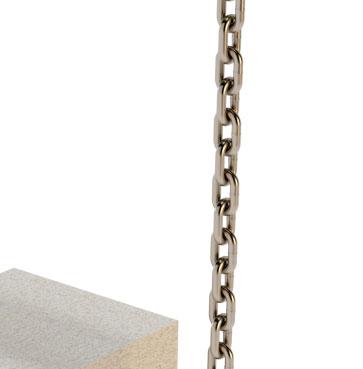
2 COLIFT Mounting System for precast concrete elements Fast and secure mounting of precast concrete elements Can be remotely released with a cord CE marking Standardized mounting system for various load levels Minimum need for maintenance The COLIFT Mounting System is designed for easy and time-saving lifting and handling of precast concrete elements such as columns or precast beams. The mounting system can be remotely released with a cord. The COLIFT Mounting System is labeled and CE-marked according to the Machinery Directive 2006/42/EC. The system consists of a mounting shaft with a slip guard and a rope strut and serves as a mounting device for lifting, moving, and placing precast concrete elements. By attaching a releasing cord to the slip guard, the system can be remotely released after securing the element in place. Related lifting slings, wires, and cords are not part of the COLIFT Mounting System delivery.
3 Contents About the COLIFT Mounting System 5 1. Product properties Material properties and quality Dimensions and weights of system components Standard safe working load for the COLIFT Mounting System Placing of the COLIFT Mounting System Environmental conditions Selecting the COLIFT Mounting System Selecting the COLIFT Mounting System Element weight Selecting lifting slings for the COLIFT Mounting System Annex A - Security connections 15 Annex B - Extended safe working load 17 Annex C - Application conditions 25 Revision: 002*
4 Contents Annex D - Inspection of the COLIFT Mounting System 31 Annex E - Declaration of conformity 33 Annex F - Type label 34 Installation of the COLIFT Mounting System 35 This documentation is subject to regular updates. Prior to use, check Peikko s website for updated documentation. When updated documentation is published, this version expires with immediate effect.


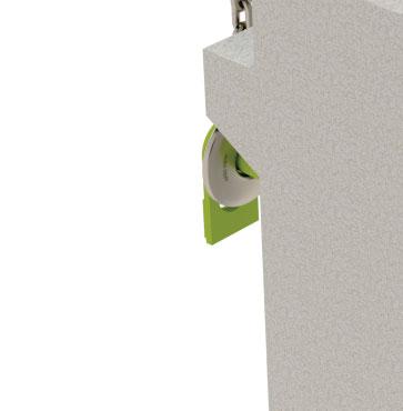
5 About the COLIFT Mounting System 1. Product properties The COLIFT Mounting System is designed for lifting and handling of precast concrete columns or beams on the construction site. The design of the COLIFT Mounting System follows the requirements defined by the European Machinery Directive 2006/42/EC. The COLIFT Mounting System is intended for lifting and tilting up concrete elements from the ground. It can also be used simultaneously in pairs for lifting long and heavy beams. The remote function of the COLIFT Mounting System enables the lifting device to be released from ground level without requiring an additional elevated working platform. The system s versatility makes it possible to attach it to precast elements of various dimensions and to use different types of slings. COLIFT Mounting System introduction The COLIFT Mounting System consists of the following main parts: Mounting shaft Slip guard Rope strut Slings (customer selection) Figure 1. Assembled COLIFT Mounting System. The mounting shaft (Figure 2) is installed in a hole in the precast element and it transfers the weight of the precast element to the slings. The mounting shaft is available in four standard models offering different safe working load ranges. Rope strut Slings The slip guard secures the position of the slings on the mounting shaft and allows remote disassembling of the system from the precast element. After removing the slip guard with the attached cord, the mounting shaft can be pulled out from the precast element. The rope strut (Figure 3) is attached to the lifting slings, ensuring that the slings are always vertical and do not touch the precast element. The rope strut enables the precast column to be tilted up. The distance of the slings from the precast element can be adjusted using a threaded rope holder. The rope strut also transfers compressive load from the inclined legs of the slings. The rope struts are available in three models and selected according to the dimensions of the lifted item. They can be combined with all four mounting shaft models. Mounting shaft Slip guard Figure 2. Mounting shaft with slip guard. Figure 3. Rope strut. Version: Peikko Group 12/2017 5
6 About the COLIFT Mounting System 1.1 Material properties and quality The COLIFT Mounting System s parts are produced from special steel according to Table 1: Table 1. Materials of the COLIFT Mounting System. Mounting shaft Alloy steel EN Slip guard Structural steel EN Rope strut Structural steel EN End plate Structural steel EN Nuts Carbon steel EN ISO The COLIFT Mounting System is supplied with standard primer rust protection. Peikko Group s production units are externally controlled and periodically audited on the basis of production certifications and product approvals issued by various organizations, including VTT Expert Services, Nordcert, SLV, TSUS, and SPSC. 1.2 Dimensions and weights of system components The dimensions of the standard models of COLIFT Mounting System are in Table 2 and Table 3. Table 2. Dimensions of the mounting shaft and slip guard. Mounting shaft Slip guard l ms d ms h h lock b Unit MW d70 MW d90 MW d115 MW d140 d ms mm l ms mm h lock mm h mm b mm Mounting shaft kg Slip guard kg COLIFT Mounting System / Original instructions
7 About the COLIFT Mounting System Table 3. Dimensions of the rope strut. l sb d at Thread Unit PS 01 PS 02 PS 03 d at mm Thread M M M l sb,min mm l sb,max mm Weight kg * The rope strut can be combined with every mounting shaft model. NOTE: Standard delivery for each COLIFT Mounting System includes a mounting shaft, a rope strut, and a slip guard. Lifting slings and connecting ropes are not supplied by Peikko. WARNING: All parts of the COLIFT Mounting System produced by Peikko Group are intended only for the purposes stated in this technical manual. Never use any part of the mounting system for other purposes. 1.3 Standard safe working load for the COLIFT Mounting System The resistance of the COLIFT Mounting System is determined by a design concept that refers to the following standards and regulations: Machinery Directive 2006/42/EC EN ISO EN DIN 15429:1978 DGUV DGUV DGUV The limiting factor that determines the working life of the COLIFT Mounting System is the fatigue of the material. Based on the requirements according to EN 13001, the COLIFT Mounting System is designed for 90,000 load cycles. Version: Peikko Group 12/2017 7
8 About the COLIFT Mounting System The minimum working distance between the lifting slings and the closest element surface is 50 mm. For columns with no corbels, this is measured from the element surface. If corbels are used, it is the distance between the corbel and the lifting sling (Figure 4 and Figure 5). Figure 4. Minimum spacing between slings and column without corbels. Figure 5. Minimum spacing between slings and column with corbels. min. 50 mm min. 50 mm L k L k The COLIFT Mounting System can be used in compliance with two design concepts: Standard safe working load Extended safe working load Standard safe working load The standard safe working loads are determined for the most demanding case that can occur during the lifetime of the COLIFT Mounting System, where the maximum allowed wear of the mounting shaft is 5% with the maximum dynamic factor equal to 1.3 (maximum lifting speed 0.6 m/s and hoisting class HC2). The standard solution capacities in Table 4 are based on the dimensions of the mounting shaft and the lever arm L k. NOTE: Before selecting the mounting shaft, please consider that the minimum compressive strength of the precast concrete element must be at least 40 MPa. If the compressive strength of the concrete is less than 40 MPa, use a different lifting system for demolding and transportation. The design criteria for lower concrete strength can be found in Annex B. 8 COLIFT Mounting System / Original instructions
9 About the COLIFT Mounting System Table 4. Standard safe working load (SWL) capacities of the COLIFT Mounting System [tons]. min. 50 mm G k L k G k = Weight of the element [tons] MW d70 MW d90 MW d115 MW d140 Spacing Length SWL [t] SWL [t] SWL [t] SWL [t] L k [mm] WARNING: The mounting shaft must be loaded symmetrically during the lifting process. The spacing between the slings and the lifted element surface must be equal on both sides. The symmetry of the load on the mounting shaft must be checked and adjusted every time. Extended safe working load The extended safe working load solution provides a more precise definition of the safe working load based on the real wear of the mounting shaft, the dynamic factor, and the concrete grade of the precast element. This solution requires individual justification of the wear and defining dynamic factor based on the real lifting speed and the type of crane. More information can be found in Annex B. Version: Peikko Group 12/2017 9
10 About the COLIFT Mounting System The rope strut is designed to transfer horizontal forces from the slings in combination with all mounting shaft models. The horizontal forces in the rope strut depend on the lifting sling inclination (angle β) and the lifted weight of the element. The maximum permitted angle of the lifting sling is 15 (Figure 6). Greater angles are not permitted due to excessive load increase. Figure 6. Transfer of horizontal forces to rope strut. G k β max = 15 F Rd F Rd G k /2 G k /2 NOTE: The concrete element must be designed to withstand its own dead-weight during lifting and handling. Additional reinforcement may be needed to handle these effects during lifting. Please consider requirements according to EN and EN WARNING: Never assume sufficient reinforcement make precise calculations. Too little reinforcement can result in severe accidents and collapsing elements. 10 COLIFT Mounting System / Original instructions


11 About the COLIFT Mounting System 1.4 Placing of the COLIFT Mounting System The mounting shaft is placed into a hole in the precast element with both ends of the shaft protruding from the element by the same length (the precast element is balanced on the middle of the shaft). An appropriate diameter of the mounting shaft must be considered before casting the precast element. The hole for the mounting shaft is created using a plastic tube with diameters presented in Table 5. The diameter of the casted tube should be at least 10 mm bigger than the diameter of the mounting shaft. The resulting center of gravity of the precast element must be considered when placing the tube in the formwork to ensure that the element will be in a balanced position during lifting and handling on the construction site. Check Annex C (Application conditions) before designing and using the COLIFT Mounting System. Figure 7. Hole for mounting shaft in precast element. Figure 8. Mounting shaft placed in the hole. Mounting shaft The minimum inner diameters of tubes used for mounting shafts are presented in the following table. Table 5. Minimum tube diameters for the mounting shaft. Unit MW d70 MW d90 MW d115 MW d140 Minimum inner diameter of tube Ø [mm] The maximum diameter of the hole is limited to 1.5 times the mounting shaft diameter. If the hole is too big for the mounting shaft, the precast element may move unexpectedly. Figure 9. Installation position of the tube for the mounting shaft. Center of gravity of the column Lifting direction x x Position of the tube for the mounting shaft Version: Peikko Group 12/
.")
12 About the COLIFT Mounting System 1.5 Environmental conditions The COLIFT Mounting System can be used at temperatures of between -20 C and +80 C. COLIFT Mounting System s components must be stored and protected in dry conditions, preferably under a roof or suitable storage location (see Figure 10). Components may corrode if they are unprotected and exposed to outdoor weather conditions such as large temperature variations, ice, humidity, acidic atmosphere, or salt and sea water impact. Figure 10. Proper storage of COLIFT parts. 12 COLIFT Mounting System / Original instructions
13 Selecting the COLIFT Mounting System 2. Selecting the COLIFT Mounting System The use of the COLIFT Mounting System must be taken into account during the design of the precast element. Although the COLIFT Mounting System is a lifting device that is only temporarily attached to the precast element on the construction site, the system requires an opening for the mounting shaft with the correct diameter and position to be created when the element is cast. The following aspects must be considered when selecting an appropriate model of COLIFT Mounting System: What are the element properties (size, weight, geometry)? Where is the center of gravity? What is the lifting process after production and who is responsible for it? (Acceleration forces, type of crane, trained personnel) Which equipment is needed for the lifting process to ensure that design assumptions are realized? The COLIFT Mounting System can be selected and used only by trained personnel who are familiar with the information presented in this technical manual and local requirements for safe handling and lifting. 2.1 Element weight The weight of the precast element can be calculated according to EN The total weight of concrete element is known during the design of the element, so this information is used to select the correct diameter of the mounting shaft and the diameter of the tube to be placed in the formwork at the precast factory. With heavily reinforced elements, the weight of the reinforcement should be considered separately. 2.2 Selecting lifting slings for the COLIFT Mounting System The lifting slings transfer the element s load from the mounting shaft to the crane. The load transferred by the slings depends on the inclinations of the chain above the rope strut. This inclination is defined by angle β from the vertical. The maximum permitted angle that can be used with the COLIFT Mounting System is 15. Grater angles are not permissible due to excess load increase. The correct lifting slings must be selected by trained personnel. Selecting the wrong slings may cause failure of the system and severe injuries or death. The minimum safe working load that can be transferred by one leg of the sling is 0.67 G k whereas G k is the element s dead-weight as shown in Figure 11. If two COLIFT Mounting Systems are used to lift a precast beam, each leg of the lifting slings is load-bearing. The minimum safe working load transferred by one leg of the slings is equal to 0.67 G k /2 when the beam is horizontal (Figure 12). Inclination of the beam during lifting must be considered as additional load on the slings. Lifting accessories (shackles, hooks, etc.) that are used for attaching the slings to the COLIFT Mounting System must have sufficient capacity to allow a safe working load on the slings. Version: Peikko Group 12/
14 Selecting the COLIFT Mounting System Figure 11. Minimum capacity for one leg of the sling with a precast column. Figure 12. Minimum capacity for one leg of the sling with a precast beam. = 0.67 G k /2 = 0.67 G k /2 = 0.67 G k G k = 0.67 G k /2 = 0.67 G k /2 β G k NOTE: Please note that the precast element must always be placed symmetrically on the mounting shaft to ensure that loads are the same in both legs of the slings. 14 COLIFT Mounting System / Original instructions


15 Annex A - Security connections Annex A Security connections For safety purposes, the mounting shaft, rope strut, and slip guard must be connected to lifting slings (or a hook) using additional cords, wires, or slings. These transfer the self-weight of the mounting system parts during lifting or removal from the precast element. Steel wires must have sufficient strength to transfer the self-weight of the part increased by the dynamic effect caused when removed from the precast element (Table 6). Check for adequate tensile resistance of the connecting wires, slings, or cords when using a material other than steel wire. Table 6. Minimum requirements for connecting wires. Minimum diameter of the steel wire Minimum tensile resistance Standard Ø6 19 kn EN Figure 13. Attaching the mounting shaft to the lifting sling with steel wire. Figure 14. Attaching the slip guard to the lifting sling with steel wire. NOTE: Use an appropriate length of cord for remote control of the slip guard to have a safe distance to operate this from. Version: Peikko Group 12/


16 Annex A - Security connections Figure 15. Attaching the rope strut to the oblong ring with steel wire. Figure 16. Whole system assembled, including cords for removing the slip guard and mounting shaft. Cord for remote control of the slip guard NOTE: The safety cords, or wires must be attached to the COLIFT s parts properly. Use appropriate accessories such as shackles or rope clips to attach wires. EN could be considered. 16 COLIFT Mounting System / Original instructions
17 Annex B - Extended safe working load Annex B - Extended safe working load The calculations for extended safe working load can provide a more precise solution for selecting the COLIFT capacity. Selection of the safe working load depends on the real wear of the mounting shaft, which is defined by a trained user, the lever arm Lk and the dynamic factor defined on the real lifting speed, and the type of the crane. This solution also provides further design principles for precast elements using concrete with a compressive strength of less than 40 MPa. Acceleration forces The mounting system must withstand the hoisting and acceleration forces that are present during lifting and it transfers those loads into the lifting unit. The hoisting load coefficient, called the dynamic factor, is defined according to the lifting speed and the hoisting class of the crane (according to EN ). Figure 17. Interaction between hoisting classes, hoisting speed and dynamic factor. Φ 2 2,5 2 1,5 1 0,5 HC 4 HC 3 HC 2 HC 1 V h = Hoisting speed HC i = Hoisting class Φ 2 = Dynamic factor 0 0 0,5 1 1,5 2 V h NOTE: Individual hoisting coefficient must be considered for the entire chain of transportation between the precast plant and building installation. Wear out Regular use of the mounting shaft reduces the amount of material in the areas subject to the greatest load. This reduction is represented by wearing of the mounting shaft diameter and it limits the safe working load of the COLIFT. Wear out of the mounting shaft is regularly controlled during inspection of the COLIFT Mounting System (Annex D) and further use is allowed when the load is limited according to Tables 7, 8, 9, and 10. Figure 18. Spacing length of slings and wear of the mounting shaft. d red L k Version: Peikko Group 12/
18 Annex B - Extended safe working load Table 7. Safe working loads (SWL) for mounting shaft MW d70 under various dynamic factors [tons]. Dynamic factor [-] 1.05* Spacing length L k [mm] Wear out 0% 1% 2% 3% 4% 5% d red [mm] * Dynamic factor 1.05 is defined for a lifting speed equal to 0 m/s. 18 COLIFT Mounting System / Original instructions
19 Annex B - Extended safe working load Table 8. Safe working loads (SWL) for mounting shaft MW d90 under various dynamic factors [tons]. Dynamic factor [-] 1.05* Spacing length L k [mm] Wear out 0% 1% 2% 3% 4% 5% d red [mm] * Dynamic factor 1.05 is defined for a lifting speed equal to 0 m/s. Version: Peikko Group 12/
20 Annex B - Extended safe working load Table 9. Safe working loads (SWL) for mounting shaft MW d115 under various dynamic factors [tons]. Dynamic factor [-] 1.05* Spacing length L k [mm] Wear out 0% 1% 2% 3% 4% 5% d red [mm] * Dynamic factor 1.05 is defined for a lifting speed equal to 0 m/s. 20 COLIFT Mounting System / Original instructions
21 Annex B - Extended safe working load Table 10. Safe working loads (SWL) for mounting shaft MW d140 under various dynamic factors [tons]. Dynamic factor [-] 1.05* Spacing length L k [mm] Wear out 0% 1% 2% 3% 4% 5% d red [mm] * Dynamic factor 1.05 is defined for a lifting speed equal to 0 m/s. Version: Peikko Group 12/
22 Annex B - Extended safe working load Reduction factor for lower concrete grades The safe working loads presented in Table 7, Table 8, Table 9, and Table 10 are determined for precast elements made from concrete with a minimum compressive strength of 40 MPa. For precast elements produced from lower concrete grades or during the demolding process when concrete has a lower compressive strength, the reduction factors presented in Table 11 must be used. Table 11. Reduction factor for lower concrete strength. Compressive strength of the concrete f ck [MPa] Reduction factor ξ con [-] Use linear interpolation for intermediate values. Reduced safe working loads for precast elements with a concrete strength lower than 40 MPa are calculated according to the following equation: SWL red SWL con (1) Where: SWL = Safe working load according to Table 7, Table 8, Table 9, Table 10 [tons] ξ con = Reduction factor for lower concrete strength Table 11 [-] 22 COLIFT Mounting System / Original instructions
23 Annex B - Extended safe working load Example 1 Selecting the SWL based on extended safe working loads: Figure 19. Dimensions of Example The average wear out of the mounting shaft MW d90 is equal to 2%. On the construction site, the most commonly used distance of the slings from the precast element is 100 mm and the lifting speed v h used during erection of the element is m/s. The dynamic factor for lifting speed m/s is equal to Figure 20. Definition of dynamic factor Ø 2 based on lifting speed v h. Φ 2 2,5 HC 4 2 HC 3 1,5 Φ 2 = HC 2 HC 1 0,5 V h = ,5 1 1,5 2 V h The current safe working load for mounting shaft MW d90 with the aforementioned boundary conditions is 35 t (see Table 12). Table 12. Selecting a SWL for 2% wear out of MW d90. Dynamic factor [-] 1.15 Spacing length L k [mm] Wear out 0% 1% 2% 3% 4% 5% d red [mm] Version: Peikko Group 12/
24 Annex B - Extended safe working load Example 2 - Selection of SWL based on extended safe working loads and a lower concrete grade: Figure 21. Dimensions of Example 2. f ck = 30 MPa A precast element is produced from concrete with a compressive strength of 30 MPa. The average wear out of the mounting shaft is 0%. Mounting shaft MW 115 will be used for the lifting with slings spacing equal to 50 mm. Based on the lifting speed and the type of crane, the dynamic factor is equal to Table 13. Selecting of SWL for 0% wear out for MW d115. Dynamic factor [-] 1.20 Spacing length L k [mm] Wear out 0% 1% 2% 3% 4% 5% d red [mm] The safe working load selected in Table 13 is determined for concrete with a compressive strength of 40 MPa. During lifting, the precast elements will have a compressive strength of concrete equal to 30 MPa. For this reason, the safe working load must be reduced by the reduction factor ξ con. SWL SWL 68 tons tons red con The reduced safe working load of the mounting shaft MW115 with spacing L k equal to 50 mm and compressive strength of concrete of 30 MPa is 60 tons. 24 COLIFT Mounting System / Original instructions
25 Annex C - Application conditions Annex C Application conditions Essential rules to be considered before using the COLIFT Mounting System: C1. Personnel and safety requirements All local regulation for safety of lifting and hoisting must be kept in mind at all times together with the assumptions described in this manual. The operator of the COLIFT Mounting System must be properly educated and trained to handle this device. The personnel must be familiar with the requirements presented in this technical manual. No untrained personnel may work with COLIFT Mounting System. An increased risk of crushing of hands can arise during the slinging procedure. Personal safety equipment must be used when working with the COLIFT Mounting System. NOTE: Never exceed the maximum allowable weight that can be carried by one person according to the work safety regulations. Use a crane to lift and move COLIFT parts if necessary. Only one person may give hand signals to the crane operator during lifting. C2. Loading, lifetime, and environmental conditions Visually inspect the mounting system, the lifting slings, and additional cords and wires before every use for any damage (cracks, bands, twisted and knotted slings) and ensure that all parts fit together according to this technical manual. Use a competent person who is familiar with the requirements of the COLIFT Mounting System. Take damaged components out of service immediately. NOTE: Do not use COLIFT Mounting System with missing or damaged parts (slip guard, end plate, rope strut, slings, additional wires, etc.) it can lead to hazardous situation, damage of the property or sever injures or death. Select the correct diameter of the mounting shaft based on the weight and dimensions of the lifted element. Do not overload the COLIFT Mounting System. WARNING: When the COLIFT Mounting System is severely overloaded or subjected to large dynamic load, plastic deformation of the mounting shaft can occur. When the deformation exceeds the allowable limit defined in Annex D, the mounting shaft must be taken out of service. Do not use the mounting shaft if the diameter is significantly worn down (see Annex D). Use a sufficient length of the mounting shaft for the precast element to ensure that the slings have enough space for slinging to the shaft and that they are not in contact with precast element. All parts of the COLIFT Mounting System must be secured by wire cords before lifting to prevent parts of the mounting system from falling (see Annex A). Use a sufficient diameter of tube for the mounting shaft when casting the precast element. Lifting accessories (shackles, slings, ropes, hooks) with sufficient capacity must be used. The final capacity of the COLIFT Mounting System is based on the resistance of the weakest element of the system. WARNING: Do not use slings or any other lifting accessories that are not designed for lifting purposes as this can lead to damage to property, severe injures or death. Version: Peikko Group 12/


26 Annex C - Application conditions It is strictly prohibited to weld anything on any parts of the COLIFT Mounting System. It is also strictly prohibited to shorten the mounting shaft or the rope strut or make any modifications to any parts of the COLIFT Mounting System. The lifting slings can be attached to the mounting shaft through hooks, shackles or ties from the rope with a sufficient shackle dimension (see Figure 22; Figure 23; Figure 24). Figure 22. Slings attached with hooks. Figure 23. Slings attached with shackles. Figure 24. Slings attached with rope loop and shackle. Do not attach the lifting slings to the lifting ring at the mounting shaft when lifting the precast element. This ring is only for transporting the mounting shaft (see Figure 25). Figure 25. Attaching the lifting sling to the mounting shaft. 26 COLIFT Mounting System / Original instructions
27 Annex C - Application conditions Always use a securing pin with the rope strut to secure the position of the sling at the rope holder. Figure 26. Securing the sling at rope strut. The minimum clear distance between the top surface or anything protruding out of the precast element and the rope strut is 200 mm. This enables the precast element to be tilted up without collision with the rope strut (Figure 27). Figure 27. Minimum clear distance between column surface and rope strut during tilt-up. Min. 200 mm Version: Peikko Group 12/
28 Annex C - Application conditions C3. Interaction with the precast element The precast concrete element must be designed properly to resists the loads from the mounting shaft during lifting. The COLIFT Mounting System is not intended for use in precast elements made from lightweight concrete, lightweight aggregate concrete, or autoclaved aerated concrete. Know the position of the center of gravity of precast element. To ensure stability during lifting, the mounting shaft must be attached above the center of gravity of the lifted element. (Figure 28; Figure 29) This ensures that the precast element does not tilt down during lifting. Figure 28. Position of the lifting point compared to the center of gravity of a column. Figure 29. Position of the lifting point compared to the center of gravity of a beam. G total G total G total G total The precast element must be placed in the middle between slings. If the precast element is placed eccentrically, the chains will not be loaded equally. This could cause overloading on one leg of the slings and failure of the mounting system. (See Figure 30.) The mounting shaft and the rope strut must be always placed horizontally. (See Figure 31.) The inclination of the mounting shaft or rope strut or different lengths of sling legs could cause unexpected movement of the load on the mounting system during lifting. 28 COLIFT Mounting System / Original instructions
29 Annex C - Application conditions Figure 30. Position of the load on the COLIFT Mounting System. x y x x x x Figure 31. Allowable inclination of the COLIFT Mounting Shaft. α > 0 α > 0 α = 0 α = 0 Version: Peikko Group 12/

30 Annex C - Application conditions The slings between the rope strut and the mounting shaft must always be vertical. No inclination is allowed. (Figure 32.) Figure 32. Position of the slings on the mounting shaft. C4. Lifting and handling process Avoid abrupt lifting. Avoid sudden acceleration or deceleration of the load during lifting. Do not exceed the maximum allowed lifting speed presented in this technical manual. During lifting, no-one must be in the danger zone. The weather conditions must be optimal during the lifting process. Do not use the COLIFT Mounting System when the maximum crane wind loads are exceeded. Do not rotate (pinning) the precast element during lifting or tilt-up when the element is still in contact with ground. This is to reduce the risk of unexpected movement of the load on the mounting shaft. Never work under a suspended load unless it is adequately supported from the ground. Never leave a suspended precast element unattended in mid-air when the crane does not have an operator. The operator must guide the crane operator so that the precast element does not come into contact with any obstacles or personnel. Moving elements during lifting and handling can cause crushing or severe injuries. Parts of the COLIFT Mounting System must always be visible when handling the precast element on the building site. Never remove the slip guard from the mounting shaft until the precast element is properly attached to the loadbearing construction. The COLIFT Mounting System should not be used in an area where it could be exposed to acids or acidic fumes or other chemicals that could potentially harm the parts of the mounting system. All parts should be covered before exposure to weather that could cause corrosion of the steel parts. 30 COLIFT Mounting System / Original instructions
31 Annex D - Inspection of the COLIFT Mounting System Annex D - Inspection of the COLIFT Mounting System Inspection of the COLIFT Mounting System The parts of the COLIFT Mounting System must be regularly inspected in accordance with national safety standards such as DGUV in Germany. As a lifting item, the COLIFT Mounting System can be affected by overloading, damage during misuse, weather, and fatigue, which could lead to failure of the part and severe damage to property or person. For this reason, a thorough visual inspection of all of the parts of the mounting system must be carried out at least once per year. Inspection of the cracks in the material must be carried out at least once per three years. All inspections of the COLIFT Mounting System must be carried out by qualified personnel who have appropriate technical training and experience in the field of lifting equipment and related safety regulations. The following points should be checked when inspecting the COLIFT Mounting System: Inspection process Clean all components of the mounting system before every inspection. Mounting shaft and slip guard: Carry out a visual inspection at least once per year for external damage such as: Plastic deformation (bend) due to overloading Wear out Deformation of the end plate and welded bar Missing bolts in the end plate Damage or deformation of the channel for the slip guard Plastic deformation of the slip guard Crack inspection at least once every three years No visible cracks or gauges No welding in any location The tolerances provided by the manufacturer must be complied with Rope strut: No visible cracks or deformation No damage of the thread; thread can move smoothly No damage of the spring pins; threaded tube cannot be removed completely NOTE: Do not use COLIFT Mounting System with missing or damaged parts (slip guard, end plate, rope strut, slings, additional wires, etc.). It can lead to hazardous situation, damage of the property or sever injures or death). When the plastic deformation Δ of the mounting shaft exceeds 3 mm, the mounting shaft must be removed from the service (Figure 33). Figure 33. Measuring plastic deformation of the mounting shaft. Δ Version: Peikko Group 12/


32 Annex D - Inspection of the COLIFT Mounting System When the wear of the mounting shaft diameter exceeds 5% of the original diameter, the mounting shaft must be taken out of service (see Figure 34). The limit diameters for the mounting shaft are presented in Table 14. Figure 34. Wear of the mounting shaft. Figure 35. Reduced diameter of the mounting shaft. d red,1 d red,2 d red L k d red d d red,1 red,2 2 Table 14. Limit diameters of the mounting shaft in the event of wear out. Unit COLIFT d70 COLIFT d90 COLIFT d115 COLIFT d140 Limit diameter < d red mm Inspection of the following regions is recommended: Figure 36. Inspection area for Rope Strut. Figure 37. Inspection areas for Mounting Shaft. It is recommended to record the inspections of all items with the serial number on record cards as shown in Figure 38. Figure 38. Example of a record card for the mounting system Chain record card DGUV (previous BGI 879-2) Name of the chain Release: September 2015 Hoist chain Chain sling with welded in master and end links For assembled chain sling made from parts a chain record card according DGUV must be used Peikko Group Corp. Voimakatu 3 FI Lahti Order No. Chain No. Capacity SWL Grade Length m Nominal thickness mm Weight kg Hoist chain t Manufacturer symbol *) Next inspection date Chain sling -strands/legs 1-strand β 45 β 60 t t t Inspection certificate Delivery from: No. Date Taken into use on: Taken out of use on: 32 COLIFT Mounting System / Original instructions
33 Annex E - Declaration of conformity Annex E - Declaration of conformity Version: Peikko Group 12/
34 Annex F - Type label Annex F - Type label Peikko Deutschland GmbH Peikko Deutschland GmbH Brinker Weg 15, Waldeck, Germany Brinker Weg 15, Waldeck, Germany Tel Tel Web: COLIFT Web: COLIFT Type: Mounting shaft MW d70 Type: Mounting shaft MW d90 Dimensions [mm]: Ø70 x 1200 Dimensions [mm]: Ø90 x 1400 Serial No.: Serial No.: Weight [kg]: 45 Weight [kg]: 83 Manufacture year: Manufacture year: Spacing of slings L k [mm]: Spacing of slings L k [mm]: Safe working load [tons]: Safe working load [tons]: Peikko Deutschland GmbH Peikko Deutschland GmbH Brinker Weg 15, Waldeck, Germany Brinker Weg 15, Waldeck, Germany Tel Tel Web: COLIFT Web: COLIFT Type: Mounting shaft MW d115 Type: Mounting shaft MW d140 Dimensions [mm]: Ø115 x 1800 Dimensions [mm]: Ø140 x 2000 Serial No.: Serial No.: Weight [kg]: 168 Weight [kg]: 269 Manufacture year: Manufacture year: Spacing of slings L k [mm]: Spacing of slings L k [mm]: Safe working load [tons]: Safe working load [tons]: Peikko Deutschland GmbH Peikko Deutschland GmbH Brinker Weg 15, Waldeck, Germany Brinker Weg 15, Waldeck, Germany Tel Tel Web: COLIFT Web: COLIFT Type: Rope Strut PS 01 Type: Rope Strut PS 02 Dimensions [mm]: Ø121 x Dimensions [mm]: Ø121 x Serial No.: Serial No.: Weight [kg]: 73 Weight [kg]: 61 Manufacture year: Manufacture year: Length l sb [mm]: Length l sb [mm]: Characteristic resistance F Rk [kn]: Characteristic resistance F Rk [kn]: Peikko Deutschland GmbH Brinker Weg 15, Waldeck, Germany Tel Web: Type: Dimensions [mm]: COLIFT Rope Strut PS 03 Ø121 x Serial No.: Weight [kg]: 54 Manufacture year: Length l sb [mm]: Characteristic resistance F Rk [kn]: COLIFT Mounting System: 1- Mounting shaft 2- Rope strut 3- Slip Guard Peikko Deutschland GmbH Peikko Deutschland GmbH Brinker Weg 15, Waldeck, Germany Brinker Weg 15, Waldeck, Germany Tel Tel Web: COLIFT Web: COLIFT Type: Slip Guard Type: Slip Guard Part of: Mounting shaft MW d70 Part of: Mounting shaft MW d90 Serial No.: Serial No.: Weight [kg]: 5.9 Weight [kg]: 9.4 Manufacture year: Manufacture year: Peikko Deutschland GmbH Brinker Weg 15, Waldeck, Germany Peikko Deutschland GmbH Brinker Weg 15, Waldeck, Germany Tel Tel Web: COLIFT Web: COLIFT Type: Slip Guard Type: Slip Guard Part of: Mounting shaft MW d115 Part of: Mounting shaft MW d140 Serial No.: Serial No.: Weight [kg]: 15.3 Weight [kg]: 22.3 Manufacture year: Manufacture year: NOTE: The entire labeling has certificate status and may not be modified or obscured. 34 COLIFT Mounting System / Original instructions
35 Installation of the COLIFT Mounting System Installation of the COLIFT Mounting System The COLIFT Mounting System is intended for use on construction sites. The following points must be taken into account before using the COLIFT Mounting System: All workers fulfill the requirements of the documentation and are familiar with it. The limitations of applications and restrictions are known. NOTE: A minimum concrete strength of 40 MPa is to be used for precast elements when the COLIFT Mounting System is used. Figure 39. Installation of the tube for the mounting shaft above the center of gravity. Center of gravity of the column Lifting direction x x Position of the tube for the mounting shaft WARNING: Do not use the COLIFT Mounting System when the precast element has an incompatible diameter of the tube for the mounting shaft or when the location of the tube does not guarantee that the element is properly balanced. Installation on the building site Visually inspect all of the parts of the mounting system before every use. Installation of the COLIFT Mounting System is divided into three steps: Connecting the COLIFT to the crane Attaching the mounting shaft to the precast element Removing the mounting shaft from the precast element NOTE: The COLIFT Mounting System must always be installed by trained personnel who are familiar with the requirements defined in this technical manual as well as the local lifting and safety regulations. WARNING: Always select the correct diameter of mounting shaft and correct slings according to the weight and dimensions of the lifted item. Version: Peikko Group 12/
36 Installation of the COLIFT Mounting System Connecting the COLIFT Mounting System to the crane The correct lifting slings are selected based on the weight of the precast element and the intended lifting speed. The rope strut is hung on the lifting hook with additional securing wires or slings. The weight of the rope strut is not carried by the lifting slings used for the precast element but by additional wires or slings. The slings are placed on the rope holders at the end of the rope strut and secured by safety bolts. Angle β must not be greater than 15. The threaded rope holders are screwed out/in to adjust the distance between the slings and the precast element surface. Figure 40. Maximum allowable angle β for slings 15. β h min l sb Type of spreader beam PS 01 PS 02 PS 03 Length of spreader beam [mm] Minimum height to lifting ring h min [mm] l sb,min = l sb,max = l sb,min = l sb,max = l sb,min = l sb,max = For safety purposes, the mounting shaft must be attached to the sling with steel wire (see Annex A). This ensures that the mounting shaft does not fall during removal from the precast element. The slip guard is connected by a wire to the second leg of the sling and to the cord that enables remote unlocking. The cord must have sufficient length to ensure that the operator will be a safe distance from falling parts. 36 COLIFT Mounting System / Original instructions
37 Installation of the COLIFT Mounting System Attaching the COLIFT Mounting System to the precast element The mounting shaft is installed in the precast element through the hole that is cast in the element at the precast factory. The precast element must be placed in the middle of the mounting shaft. After centering the element, the slings can be attached to the mounting shaft. The same spacing between the precast element s face and slings from both sides will ensure an even distribution of weight from the lifted element to the slings. The slip guard is installed in the final position. Before starting lifting, all of the components must be visually inspected to ensure they are attached correctly to the slings and all of the components are also secured by additional wires. NOTE: The COLIFT Mounting System must always be installed by trained personnel who are familiar with the requirements defined in this technical manual as well as the local lifting and safety regulations. Figure 41. Installing the COLIFT mounting system into the precast element. Rope strut Slip guard Mounting shaft Release cord Version: Peikko Group 12/

38 Installation of the COLIFT Mounting System Removing the COLIFT Mounting System Before removing the COLIFT Mounting System from the precast element, make sure that the element is properly connected in the final position. To remove the mounting shaft, the operator must pull the connected cord to turn the slip guard upside-down and then remove it from shaft by pulling the cord from the column. The operator must have a sufficient length of cord to be out of range of accidental falling parts. After removing the slip guard, the mounting shaft can be pulled out by crane from the column. Make sure that mounting shaft is pulled out parallel to the direction of the tube in the column. Lateral pulling could exert additional forces on the column and damage the connection of the precast element. Figure 42. Removing the COLIFT Mounting System from the precast element COLIFT Mounting System / Original instructions 2 3 4
39 Technical Manual Revisions Version: PEIKKO GROUP 12/2017. Revision:002* New cover design for 2018 added. Version: Peikko Group 12/
40 Resources DESIGN TOOLS Use our powerful software every day to make your work faster, easier and more reliable. Peikko design tools include design software, 3D components for modeling programs, installation instructions, technical manuals and product approvals of Peikko s products. peikko.com/design-tools TECHNICAL SUPPORT Our technical support teams around the world are available to assist you with all of your questions regarding design, installation etc. peikko.com/technical-support APPROVALS Approvals, certificates and documents related to CE-marking (DoP, DoC) can be found on our websites under each products product page. peikko.com/products EPDS AND MANAGEMENT SYSTEM CERTIFICATES Environmental Product Declarations and management system certificates can be found at the quality section of our websites. peikko.com/qehs
Thread protection accessories are installed at the MODIX production factory and delivered with couplers.
 Installation of MODIX Rebar Coupler Identification of the product The type of MODIX Rebar Coupler can be identified by the marking on the product. Size of the Coupler can be identified also according to
TECHNICAL MANUAL. TERADOWEL and ULTRADOWEL. Reliable Dowel System for Floor Joints
 TECHNICAL MANUAL TERADOWEL and ULTRADOWEL Reliable Dowel System for Floor Joints Version: PEIKKO GROUP 11/2018 TERADOWEL and ULTRADOWEL Reliable Dowel System for Floor Joints Dowels manufactured from high
INSPECTION AND REMOVAL CRITERIA
 INSPECTION AND REMOVAL CRITERIA ASME B30.9-1 ALLOY STEEL CHAIN SLINGS 9-1.9.5 Removal Criteria Missing or illegible sling identification. Cracks or breaks. Excessive wear, nicks, or gouges. Stretched chain
WELDA FASTENING PLATES
 FASTENING PLATES Author: Markus Junes, M. Sc. Civ. Eng. R&D Manager, Peikko Group 1. INTRODUCTION Peikko Group has launched a new family of Fastening Plate products with resistances calculated on the basis
TECHNICAL MANUAL. HPM Rebar Anchor Bolt Easy and Fast Bolted Connections
 TECHNICAL MANUAL HPM Rebar Anchor Bolt Easy and Fast Bolted Connections Version: PEIKKO GROUP 01/2015 HPM Anchor Bolt For bolted connections System benefits Standardized and approved rebar anchor bolt
Erstantie 2, FIN Villähde Tel , Fax
 www.anstar.eu 2 www.anstar.eu 3 CONTENTS Page 1 PRODUCT DESCRIPTION...4 2 MATERIALS AND STRUCTURE...4 2.1 PRODUCT RANGE...4 2.2 MATERIALS...4 2.3 MANUFACTURING...4 2.4 MANUFACTURING TOLERANCES...4 2.5
m A D e f o R b u i L D i n g L i f t i n g S y S t e m S C e - m A R K e D
 M a d e f o r b u i l d i n g b u i l t f o r l i v i n g Lif t ing Sys tem s CE - MARKED I M P R I N T KLH Massivholz GmbH Publisher and responsible for content: KLH Massivholz GmbH Version: 01/2013,
Inspec on Program Summary
 Inspec on Program Summary Inspec on program includes: Inspec on program includes: Wire Rope Wire Rope Slings Synthe c Web and Rigging Hardware Below-the-Hook Li ing Devices Custom Devices when applicable
Tube Facing Tool.
 www.swagelok.com Tube Facing Tool This manual contains important information for the safe and effective operation of the Swagelok TF72 series tube facing tool. Users should read and understand its contents
P4044. Stainless Female Lifting Eye Bolts metric sizes. Lifting Bolts & Shackles. Tel: Fax:
 Stainless Female Lifting Eye Bolts metric sizes Lifting Bolts & Shackles P4044 Material Stainless steel (A4, AISI 316). CE marked. Technical notes To DIN 582. When using lifting eye bolts it is critical
7. Operating instructions: EFL 300
 7. Operating instructions: EFL 300 Copyright 2015 by Endecotts Ltd. 59 1. Setting up Technical specifications SIEVE SHAKER MODEL: EFL 300 General Information The new EFL 300 combines the best features
TECHNICAL MANUAL. OPTIMAJOINT Free Movement Joint. Free Movement Joint System for Heavy Traffic
 TECHNICAL MANUAL OPTIMAJOINT Free Movement Joint Free Movement Joint System for Heavy Traffic Version: PEIKKO GROUP 12/2018 OPTIMAJOINT Free Movement Joint Free Movement Joint System for heavy traffic
25 TONNE HYDRAULIC PRESS MODEL NO: AHP 26
 WARNING: Read these instructions before using the machine 25 TONNE HYDRAULIC PRESS MODEL NO: AHP 26 PART NO: 7615115 OPERATION & MAINTENANCE INSTRUCTIONS LS1211 INTRODUCTION Thank you for purchasing this
Swivel Hoist Ring RIGGING ACCESSORIES. Color coded to distinguish between UNC (Red) and Metric (Silver) thread types.
 and Metric (Silver) thread types.") RIGGING ACCESSORIES Color coded to distinguish between UNC (Red) and Metric (Silver) thread types. Available in UNC and Metric thread sizes. UNC threads available in sizes from 800 pounds to 100,000 pounds,
RIGGING ACCESSORIES Color coded to distinguish between UNC (Red) and Metric (Silver) thread types. Available in UNC and Metric thread sizes. UNC threads available in sizes from 800 pounds to 100,000 pounds,
Operating Instructions and Parts Manual Lever Operated Chain Hoist JLH Series
 Operating Instructions and Parts Manual Lever Operated Chain Hoist JLH Series 1 Ton model shown JET 427 New Sanford Road LaVergne, Tennessee 37086 Part No. M-275050 Ph.: 800-274-6848 Revision H3 07/2018
WARNING. Read and become familiar with this manual BEFORE operating unit.
 Covered by one or more of the following patents: 3,828,942 5,368,429 5,586,619 5,984,605 7,556,464 7,726,901 Other patents pending. OPERATOR S MANUAL For Model 439 WARNING Read and become familiar with
Swivel Hoist Ring Page 142
 Swivel Hoist Ring Page 142 Hoist Rings Color coded to distinguish between UNC (Red) and Metric (Silver) thread types HR-125 M HR-125 Available in UNC and Metric thread sizes. UNC threads available in sizes
8 TONNE LOG SPLITTER
 8 TONNE LOG SPLITTER MODEL NO: LOGBUSTER 9 PART NO: 3402043 OPERATION & MAINTENANCE INSTRUCTIONS LS03/16 INTRODUCTION Thank you for purchasing this CLARKE 8 Tonne Log Splitter. Before attempting to use
RIGGING MANUAL English
 KH7 RIGGING MANUAL English TABLE of CONTENTS SYMBOLS... 3 1. INTRODUCTION... 4 2. system components... 4 3. SAFETY information... 5 4. Product overview... 6 5. suspending a cluster... 8 6. stacking kh7
ROBOT KR 350. Installation, Connection, Exchange. Ro/Me/03/ en. 1of 26
 ROBOT KR 350 Installation, Connection, Exchange 1of 26 e Copyright KUKA Roboter GmbH This documentation or excerpts therefrom may not be reproduced or disclosed to third parties without the express permission
H20 Beam for Elevated Slabs Application Guide
 H20 Beam for Elevated Slabs Application Guide A WORD ABOUT SAFETY High productivity depends on safety; even a minor accident causes job delays and inefficiency, which run up costs. That s why Symons, in
SERVICE MANUAL for Telescopic pole, Gripo Alu
 Telescopic pole Gripo Alu Side 1 av 11 HEPRO aid manufacturer HEPRO is a Norwegian industrial company that develops, manufactures and sells technical aids for adults and children with mobility impairment.
HD installation guide
 JANUS INTERNATIONAL 1 866 562 2580 www.janusintl.c o m 1950 1950HD installation guide RIGHT DRIVE END SHOWN LH OPPOSITE LEFT TENSION END SHOWN RH OPPOSITE PUSH-UP OPERATION 1950 1950HD SHOWN A rolling
Impact Wrench MODEL 6905B MODEL 6906
 ENGLISH Impact Wrench MODEL 6905B MODEL 6906 005305 DOUBLE INSULATION I N S T R U C T I O N M A N U A L WARNING: For your personal safety, READ and UNDERSTAND before using. SAVE THESE INSTRUCTIONS FOR
RUBBISH CHUTE TECHNICAL NOTE
 RUBBISH CHUTE TECHNICAL NOTE HAEMMERLIN - CDH GROUP 28 RUE DE STEINBOURG - BP 30045-67701 1 SAVERNE CEDEX - FRANCE Tel. + 33 (0)3 88 01 85 00 - Fax + 33 (0)3 88 01 85 39 welcome@haemmerlin.com - www.haemmerlin.com
Repair manual. Fifth-wheel coupling JSK 38/50
 Repair manual Fifth-wheel coupling JSK 38/5 ZDE 199 3 12 E 6/212 1 Foreword Table of contents Page Fifth wheel couplings are connecting parts that must comply with very high safety requirements and must
PUSH-PULL-PROPS. and accessories ROBUSTA-GAUKEL GMBH MOUNTING TECHNOLOGY &CO.KG
 PUSH-PULL-PROPS and accessories MOUNTING TECHNOLOGY ROBUSTA-GAUKEL GMBH &CO.KG MOUNTING TECHNOLOGY PUSH-PULL-PROPS AND ACCESSORIES INDEX General information...................... 3 Push-pull-prop Type
Sport-Thieme. Handball Goal. Assembly instruction. 3x2 m, Free-standing with Fixed Net Brackets
 Assembly instruction Sport-Thieme Handball Goal Cat.-no.: 115 0953 2392905 239 2918 113 6500 239 2400 239 2413 3x2 m, Free-standing with Fixed Net Brackets Thanks for choosing Sport-Thieme equipment! In
installation guide
 JANUS INTERNATIONAL 1 866 562 2580 w w w. j a n u s i n t l. c o m 2000 2500 3000 installation guide RIGHT DRIVE END SHOWN LH OPPOSITE LEFT TENSION END SHOWN RH OPPOSITE PUSH-UP OPERATION 2000 2500 3000
UNIVERSAL WORKSTATION
 ASSEMBLY AND OPERATING INSTRUCTIONS UNIVERSAL WORKSTATION FOX Model F50-179 1 Universal Workstation FOX MODEL F50-179 TABLE OF CONTENTS Safety instructions Page 3 Specific safety instructions for workbenches..
Nibbler MODEL JN1601. WARNING: For your personal safety, READ and UNDERSTAND before using. SAVE THESE INSTRUCTIONS FOR FUTURE REFERENCE.
 ENGLISH Nibbler MODEL JN60 00477 DOUBLE INSULATION I N S T R U C T I O N M A N U A L WARNING: For your personal safety, READ and UNDERSTAND before using. SAVE THESE INSTRUCTIONS FOR FUTURE REFERENCE. SPECIFICATIONS
 GENERAL OPERATIONAL PRECAUTIONS WARNING! When using electric tools, basic safety precautions should always be followed to reduce the risk of fire, electric shock and personal injury, including the following.
ENGLISH (Original instructions) INSTRUCTION MANUAL. Drill DS4012 DOUBLE INSULATION. IMPORTANT: Read Before Using.
 INSTRUCTION MANUAL. Drill DS4012 DOUBLE INSULATION. IMPORTANT: Read Before Using.") ENGLISH (Original instructions) INSTRUCTION MANUAL Drill DS402 05402 DOUBLE INSULATION IMPORTANT: Read Before Using. ENGLISH (Original instructions) SPECIFICATIONS Model DS402 Capacities Steel 3 mm Wood
ENGLISH (Original instructions) INSTRUCTION MANUAL Drill DS402 05402 DOUBLE INSULATION IMPORTANT: Read Before Using. ENGLISH (Original instructions) SPECIFICATIONS Model DS402 Capacities Steel 3 mm Wood
ELECTRIC SLIP ROLL MACHINE. Model: ESR-1300X2.5/ESR-1300X4.5 ESR-1550X3.5/ESR-1580X2.0
 ELECTRIC SLIP ROLL MACHINE Model: ESR-1300X2.5/ESR-1300X4.5 ESR-1550X3.5/ESR-1580X2.0 Operation Manual Table of contents I MAIN SPECIFICATION...2 II SAFETY INSTRUCTIONS.. 2 III OPERATION INSTRUCTIONS..4
SET-UP & MAINTENANCE GUIDE. DME Helical Gear Stack Mold Centering Devices
 SET-UP & MAINTENANCE GUIDE DME SECTION A Safety Procedures Table of Contents Safety Procedures... 2-4 General Description... 5 Assembly and Initial Setup... 6 On-Site Setup and Adjustment... 7-9 Disassembly
Technical description
 STAHLWILLE Standard Manoskop 721 Service Manoskop 730 List of contents Technical description... 27 ã=important safety points... 30 Operation... 32 Maintenance... 42 Cleaning the Manoskop... 47 Accessories...
The object of these Operating Instructions is to assist you in the correct safe and economical use of the TORSIOMAX torque screwdriver.
 Preface The object of these Operating Instructions is to assist you in the correct safe and economical use of the TORSIOMAX torque screwdriver. Target group for these Operating Instructions These Operating
TH450A-T TH550A-T THP550-T/TS3000
 0 TH450A-T TH550A-T THP550-T/TS3000 INSTRUCTION MANUAL CEILING TYPE (OVERHEAD TRAVELING TYPE) INDUSTRIAL ROBOT SPECIFICATIONS Notice 1. Make sure that this instruction manual is delivered to the final
Impact Wrench MODEL TW1000. WARNING: For your personal safety, READ and UNDERSTAND before using. SAVE THESE INSTRUCTIONS FOR FUTURE REFERENCE.
 ENGLISH Impact Wrench MODEL TW000 00605 DOUBLE INSULATION I N S T R U C T I O N M A N U A L WARNING: For your personal safety, READ and UNDERSTAND before using. SAVE THESE INSTRUCTIONS FOR FUTURE REFERENCE.
Operating Instructions and Parts Manual L-100 Series Hand Chain Hoists
 Operating Instructions and Parts Manual L-100 Series Hand Chain Hoists For L100-200 serial no. 15070001 and higher For L100-300 serial no. 15070043 and higher For L100-1500 serial no. 15070088 and higher
Operating Instructions K-POWERgrip EWL Always on the safe site.
 Operating Instructions K-POWERgrip EWL 4941. Always on the safe site. KaVo Elektrotechnisches Werk GmbH Wangener Straße 78 D-88299 Leutkirch A 1 User information...2 A 1.1 Meaning of the pictograms...2
Meva Guided Screens MGS Technical Instruction Manual
 Meva Guided Screens MGS Technical Instruction Manual Product Characteristics: The MEVA Guided Screens (MGS) system encloses complete floors especially in high-rise construction independent of the height
Installation and Operational Instructions for ROBA -DS couplings Type 95. _ (disk pack HF) Sizes
 Sizes") 95. _ (disk pack HF) Sizes 6 22 Please read these Operational Instructions carefully and follow them accordingly! Ignoring these Instructions may lead to malfunctions or to coupling failure, resulting
95. _ (disk pack HF) Sizes 6 22 Please read these Operational Instructions carefully and follow them accordingly! Ignoring these Instructions may lead to malfunctions or to coupling failure, resulting
Sport-Thieme Handball Goal, 3x2 m, Free-Standing or socketed
 Assembly instructions Art.-Nr.: 201 0915 203 4502 Sport-Thieme Handball Goal, 3x2 m, Free-Standing or socketed 0218214 2018 Sport-Thieme GmbH D-38367 Grasleben Germany sport-thieme.com info @sport-thieme.com
SHBP10M HYDRAULIC PRESS WITH MANDRELS
 SHBP10M HYDRAULIC PRESS WITH MANDRELS OWNER S MANUAL FOR YOUR SAFETY PLEASE READ THESE INSTRUCTIONS CAREFULLY AND RETAIN THEM FOR FUTURE USE. SPECIFICATION MAX CAPACITY STROKE WORK RANGE WEIGHT 10 TONNE
Fifth-wheel coupling JSK 38/50
 Repair manual Fifth-wheel coupling JSK 38/5 ZDE 199 3 12 E 6/25 1 LT SK38C-3 English RevA Foreword Table of contents Page Fifth wheel couplings are connecting parts that must comply with very high safety
MODEL 83 Pail Handler
 MORSE MFG. CO., INC. 727 West Manlius Street P.O. Box 518 East Syracuse, NY 13057-0518 Phone: 315-437-8475 Fax: 315-437-1029 Email: service@morsemfgco.com Website: www.morsemfgco.com COPYRIGHT 2005 MORSE
Operating and Maintenance Instructions Keep for future reference
 Operating and Maintenance Instructions Keep for future reference TM400 Log Splitter 1 Index SAFETY... 3 LABELS.... 4 QUICK GUIDE including storage and transport... 5 IN-DEPTH INSTRUCTIONS.... 6 OPERATING
Products for fixing to Steelwork and Decking
 Products 8.0 Beam Clamp - Single Support 8.1 Universal Joint for any variable Angle Adjustment 8.2 Beam Clamp TCS for Header Rails 8.3 Beam Clip for Cross Support/ Dimensioning of Bolts 8.4 Beam Clip for
Safety Instructions Manual Original Instructions - RRM2
 Radius Roller RRM2 Safety Instructions Manual Original Instructions - RRM2 Safety Manual 1 General Operator and Supervisor Information Signal Word Definition Signal Word Panel 2 Shop Press Signal Word
Tapping Screw (W/Flange) 46 Cord Armor 47 Tube (D) 48 Cord. 45 Cord Clip. Tapping Screw (W/Flange) 10 Gear Cover Ass'y. 12 Socket (B) Ass'y
 46 Cord Armor 47 Tube (D) 48 Cord. 45 Cord Clip. Tapping Screw (W/Flange) 10 Gear Cover Ass'y. 12 Socket (B) Ass'y") W8VB The exploded assembly drawing should be used only for authoized service center. W8VB Item No. Part time 1 Magnetic Hex. Socket 2 Sub Stopper 3 O-Ring (S-16) 4 Locator (A) 5 Lock Sleeve (A) 6 O-Ring
W8VB The exploded assembly drawing should be used only for authoized service center. W8VB Item No. Part time 1 Magnetic Hex. Socket 2 Sub Stopper 3 O-Ring (S-16) 4 Locator (A) 5 Lock Sleeve (A) 6 O-Ring
MANUAL SEALLESS STEEL STRAPPING TOOL MODEL A332
 OPERATION MANUAL / SPARE PARTS LIST MANUAL SEALLESS STEEL STRAPPING TOOL MODEL A332 13.2250.01 INDEX PAGE 1 SAFETY INSTRUCTIONS 2 2 WARRANTY CONDITIONS AND LIABILITY 3 3 APPROPRIATE USE 3 4 TECNICAL DATA
European Technical Approval ETA-10/0413
 ETA-Danmark A/S Kollegievej 6 DK-2920 Charlottenlund Tel. +45 72 24 59 00 Fax +45 72 24 59 04 Internet www.etadanmark.dk Authorised and notified according to Article 10 of the Council Directive 89/106/EEC
SHHP20 FLOOR STANDING HYDRAULIC PRESS
 SHHP20 FLOOR STANDING HYDRAULIC PRESS OWNER S MANUAL 20 TON MAX CAPACITY FOR YOUR SAFETY PLEASE READ THESE INSTRUCTIONS CAREFULLY AND RETAIN THEM FOR FUTURE USE. SPECIFICATION MAX CAPACITY STROKE WORK
Wall Mount Bracket YM-81
 CN/JA/EN/DE/FR/ES/IT/SV/RU/PT/TR/NL/PL/FI/CS/NO/LT/TH/ID/MS/VI/TW/KO/AR Wall Mount Bracket YM-81 English User s Guide Deutsch Bedienungsanleitung Français Mode d emploi Español Italiano Svenska Português
OXDALE PRODUCT LTD OPERATING AND MAINTENANCE MANUAL TM400 AND TM400 BIG BASE LOG SPLITTER KEEP FOR FUTURE USE
 OXDALE PRODUCT LTD OPERATING AND MAINTENANCE MANUAL TM400 AND TM400 BIG BASE LOG SPLITTER KEEP FOR FUTURE USE 1 CONTENTS Safety 3 Labels 5 Quick Guide 6 In Depth Instructions 8 Operating Instructions 12
SAFETY AND OPERATING MANUAL. Portable versatile workstation
 SAFETY AND OPERATING MANUAL Original instructions Portable versatile workstation wu063 1 2 3 4 5 6 7 8 9 Safety instructions Warning! When using this product basic safety precautions should always be followed.
Experience the Hi-Lite Advantage
 Experience the Hi-Lite Advantage 12K Aluminum Shoring System INTRODUCTION The 12K Shoring System is primarily a hand-set system. It can also be handled with a crane, and may also be used quite successfully
Safety clamps, inc. Operation, Maintenance and Repair Manual for. Model HBC. Home of the big Bite Lifting Clamp
 Safety clamps, inc. Home of the big Bite Lifting Clamp Operation, Maintenance and Repair Manual for Model HBC Products manufactured by Safety Clamps, Inc. meet and/or exceed ANSI/ASME B30.20 standards
Operator's manual. TruTool N 1000 (1B1) english
 english") Operator's manual TruTool N 1000 (1B1) english Table of contents 1. Safety...4 1.1 General safety information...4 1.2 Specific safety information...5 2. Description...6 2.1 Intended use...7 2.2 Technical
Operator's manual TruTool N 1000 (1B1) english Table of contents 1. Safety...4 1.1 General safety information...4 1.2 Specific safety information...5 2. Description...6 2.1 Intended use...7 2.2 Technical
OWNER'S MANUAL TIE ROD, WALL & FLOOR MOUNTED JIBS. Model JIB-HC, JIB-LC, JIB-FM
 Vestil Manufacturing Company 999 N. Wayne Street, P.O. Box 507 Angola, IN 6703 USA Phone (60) 665-7586 Fax (60) 665-339 sales@vestil.com www.vestil.com Revised 09-0 A company dedicated to solving ergonomic
Load application in load cells - Tips for users
 Load application in load cells - Tips for users Correct load application on the load cells is a prerequisite for precise weighing results. Be it load direction, support structure or mounting aids load
ENGLISH (Original instructions) INSTRUCTION MANUAL. Shear Wrench 6922NB DOUBLE INSULATION. IMPORTANT: Read Before Using.
 INSTRUCTION MANUAL. Shear Wrench 6922NB DOUBLE INSULATION. IMPORTANT: Read Before Using.") ENGLISH (Original instructions) INSTRUCTION MANUAL Shear Wrench 69NB 00498 DOUBLE INSULATION IMPORTANT: Read Before Using. ENGLISH (Original instructions) SPECIFICATIONS Model 69NB Bolt size M6, M0, M
ENGLISH (Original instructions) INSTRUCTION MANUAL Shear Wrench 69NB 00498 DOUBLE INSULATION IMPORTANT: Read Before Using. ENGLISH (Original instructions) SPECIFICATIONS Model 69NB Bolt size M6, M0, M
Pow-R-Feed Systems Service Manual
 Pow-R-Feed Systems Service Manual Important Safety Instructions Please read this manual carefully and follow its instructions. Improper use or failure to follow these instructions could result in serious
Thank you for purchasing our product! *Please read these instructions and follow them step by step.*
 07/07/08.rev1 PAGE 1 OF 11 601AL VERTICAL 60120VL LIFT W/CHAIN DRIVE WINCH Thank you for purchasing our product! *Please read these instructions and follow them step by step.* Step 1. Separate and group
MANUAL SEALLESS STEEL STRAPPING TOOL MODEL A335
 OPERATION MANUAL / SPARE PARTS LIST MANUAL SEALLESS STEEL STRAPPING TOOL MODEL A335 13.2810.01 INDEX PAGE 1 SAFETY INSTRUCTIONS 2 2 WARRANTY CONDITIONS AND LIABILITY 3 3 APPROPRIATE USE 3 4 TECNICAL DATA
400A 40113V, 401A 40120V, & 401AL 40120VL ALUMINUM VERTICAL 4000 LB LIFT INCLUDES SCREW LEG ASSEMBLY INSTRUCTIONS
 12/11/07 PAGE 1 OF 12 400A 40113V, 401A 40120V, & 401AL 40120VL ALUMINUM VERTICAL 4000 LB LIFT INCLUDES SCREW LEG ASSEMBLY INSTRUCTIONS Thank you for purchasing our product! *Please read these instructions
Operating Instructions and Parts Manual L-100 Series Hand Chain Hoists
 Operating Instructions and Parts Manual L-100 Series Hand Chain Hoists For L100-200 serial no. 15070001 and higher For L100-300 serial no. 15070043 and higher For L100-1500 serial no. 15070088 and higher
Instruction manual for STA 1 sectional door operator
 Instruction manual for STA 1 sectional door operator Sectional door operator STA 1 / Rev. 0.3 1 GB 1. Contents 3. General safety instructions 1. Contents 2 2. Key to symbols 2 3. General safety instructions
Sales and Service
 OPERATION MANUAL / SPARE PARTS LIST MANUAL SEALLESS STEEL STRAPPING TOOL MODEL A333 13.2370.01 INDEX PAGE 1 SAFETY INSTRUCTIONS 2 2 WARRANTY CONDITIONS AND LIABILITY 3 3 APPROPRIATE USE 3 4 TECNICAL DATA
SCREW JACKS Operating Instructions
 INS114EN.5 SCREW JACKS Operating Instructions Sweden Int +46 372 265 00 info@swedrive.se Vat.no SE556145631901 138-4551 1 Table of Contents 1. Health and Safety... 3 1.1. Notice about safety... 3 1.2.
MTS-SP100. RENOGY Pole Mount System E Philadelphia St, Ontario, CA Version: 1.2
 MTS-SP100 RENOGY Pole Mount System 2775 E Philadelphia St, Ontario, CA 91761 1-800-330-8678 1 Version: 1.2 Important Safety Instructions Please save these instructions. This manual contains important safety,
High Speed Drill MODEL WARNING: For your personal safety, READ and UNDERSTAND before using. SAVE THESE INSTRUCTIONS FOR FUTURE REFERENCE.
 ENGLISH High Speed Drill MODEL 6501 003002 DOUBLE INSULATION I N S T R U C T I O N M A N U A L WARNING: For your personal safety, READ and UNDERSTAND before using. SAVE THESE INSTRUCTIONS FOR FUTURE REFERENCE.
Table of Contents. What's New in GRAITEC Advance BIM Designers 2018 R2 ADVANCE BIM DESIGNERS CONCRETE SERIES... 4
 What's New 2018 R2 Table of Contents ADVANCE BIM DESIGNERS CONCRETE SERIES... 4 REINFORCED CONCRETE FOOTING DESIGNER... 4 Multi-layer soil calculation... 4 Bottom Constructive Reinforcement... 5 REINFORCED
Installation and Connection Manual
 Installation and Connection Manual (E Controller) Kawasaki Heavy Industries, Ltd. 90202-1003DEA PREFACE This manual explains the installation and connection procedures for Kawasaki Painting Robot. Read
Impact Wrench. 19 mm (3/4 ) MODEL 6906
 MODEL 6906") Impact Wrench 9 mm (3/4 ) MODEL 6906 002290 DOUBLE INSULATION I N S T R U C T I O N M A N U A L WARNING: For your personal safety, READ and UNDERSTAND before using. SAVE THESE INSTRUCTIONS FOR FUTURE REFERENCE.
Impact Wrench 9 mm (3/4 ) MODEL 6906 002290 DOUBLE INSULATION I N S T R U C T I O N M A N U A L WARNING: For your personal safety, READ and UNDERSTAND before using. SAVE THESE INSTRUCTIONS FOR FUTURE REFERENCE.
TYPE 3740XL EXTRA LARGE WET RUNNING CARTRIDGE SPLIT SEAL
 1 Foreword These instructions are provided to familiarize the user with the seal and its designated use. The instructions must be read and applied whenever work is done on the seal, and must be kept available
EKX Full-Range Loudspeaker Accessories
 EKX Full-Range Loudspeaker Accessories EKX-BRKT12, EKX-BRKT15, and EKX-TCA en Installation Note en 3 Table of contents 1 Safety 4 1.1 Safety point 6 2 Installation 7 2.1 Wall mount bracket 7 2.2 Truss
Floating Lake Truss Dock Instructions
 Table of Contents Floating Lake Truss Dock Instructions 1. Dock Assembly and Set-Up 1.1 Installing Dock Floats 1.2 Positioning Quick Clips 1.3 Installing Anchor Posts 1.4 Installing Docks into the Water
Bolt Material Types and Grades 1- Bolts made of carbon steel and alloy steel: 4.6, 4.8, 5.6, 5.8, 6.8, 8.8, 10.9 Nuts made of carbon steel and alloy
 Bolt Material Types and Grades 1- Bolts made of carbon steel and alloy steel: 4.6, 4.8, 5.6, 5.8, 6.8, 8.8, 10.9 Nuts made of carbon steel and alloy steel: 4, 5, 6, 8, 10, 12 2- Bolts made of stainless
6o ft (18.3 m) Southwest Windpower, Inc West Route 66 Flagstaff, Arizona USA Phone: Fax:
 Southwest Windpower, Inc West Route 66 Flagstaff, Arizona USA Phone: Fax:") 6o ft (18.3 m) sectional MONOPOLE TOWER INSTALLATION MANUAL Southwest Windpower, Inc. 1801 West Route 66 Flagstaff, Arizona 86001 USA Phone: 928.779.9463 Fax: 928.779.1485 www.skystreamenergy.com 3-CMLT-1390-01
6o ft (18.3 m) sectional MONOPOLE TOWER INSTALLATION MANUAL Southwest Windpower, Inc. 1801 West Route 66 Flagstaff, Arizona 86001 USA Phone: 928.779.9463 Fax: 928.779.1485 www.skystreamenergy.com 3-CMLT-1390-01
User s Manual For CT Model IMB
 User s Manual For CT Model IMB 2 of (13) Contents: A. Introduction... 3 B. Steps on receipt and opening the cases... 3 C. Transportation and handling... 3 D. Unpacking the transformer... 4 E. Storage...
GENERAL OPERATIONAL PRECAUTIONS PRECAUTIONS ON USING CUT-OFF MACHINE
 GENERAL OPERATIONAL PRECAUTIONS WARNING! When using electric tools, basic safety precautions should always be followed to reduce the risk of fire, electric shock and personal injury, including the following.
ENGLISH (Original instructions) INSTRUCTION MANUAL. Drill MT600 MT601 DOUBLE INSULATION. IMPORTANT: Read Before Using.
 INSTRUCTION MANUAL. Drill MT600 MT601 DOUBLE INSULATION. IMPORTANT: Read Before Using.") ENGLISH (Original instructions) INSTRUCTION MANUAL Drill MT600 MT60 003635 DOUBLE INSULATION IMPORTANT: Read Before Using. ENGLISH (Original instructions) SPECIFICATIONS Model MT600 MT60 Capacities Steel
ENGLISH (Original instructions) INSTRUCTION MANUAL Drill MT600 MT60 003635 DOUBLE INSULATION IMPORTANT: Read Before Using. ENGLISH (Original instructions) SPECIFICATIONS Model MT600 MT60 Capacities Steel
TYPE 3740/3740D WET/DRY RUNNING CARTRIDGE SPLIT SEAL
 1 Foreword These instructions are provided to familiarize the user with the seal and its designated use. The instructions must be read and applied whenever work is done on the seal, and must be kept available
Bending Roll Machine 4126
 Bending Roll Machine 4126 Operating Instructions Table of contents Main components...4 Operation...5 Safety...7 Service and maintenance... 12 Machine plates and stickers... 13 Dismantling the bending
Save time! Read the entire manual before beginning Hoister installation.
 7801BSZ: 60 (27 kg) System 7802BSZ: 90 (41 kg) System 7803BSZ: 145 (66 kg) System 7806BSZ: 200 (91 kg)system Suspenz 8725 Roswell Road, Suite O-220, Atlanta, GA USA 30350 Tel: 866-SUSPENZ or 770-518-0045
COFFEE LABORATORY WHITE STONE VA TEL
 1. Technical specifications 4. Operating instructions: Octagon 200 Copyright 2015 by Endecotts Ltd. 21 1. Setting up Technical specifications SIEVE SHAKER MODEL: Octagon 200 General Information The sieve
Save time! Read the entire manual before beginning Hoister installation.
 Harken, Inc. 1251 E. Wisconsin Ave. Pewaukee, WI 53072 USA Tel: 262-691-3320 Fax: 262-691-3008 Email: hoister@hoister.com Web: www.hoister.com WARNING!: Strictly follow all instructions to avoid an accident,
Sport-Thieme Safety Aluminium Mini Training Goal
 Assembly instructions Art.-Nr.: 116 3852 Sport-Thieme Safety Aluminium Mini Training Goal 0218214 2018 Sport-Thieme GmbH D-38367 Grasleben Germany sport-thieme.com info @sport-thieme.com Phone: +49 53
ENGLISH (Original instructions) INSTRUCTION MANUAL. Drill DOUBLE INSULATION. IMPORTANT: Read Before Using.
 INSTRUCTION MANUAL. Drill DOUBLE INSULATION. IMPORTANT: Read Before Using.") ENGLISH (Original instructions) INSTRUCTION MANUAL Drill 64 642 643 007894 DOUBLE INSULATION IMPORTANT: Read Before Using. ENGLISH (Original instructions) SPECIFICATIONS Model 64 642 643 Capacities Steel
ENGLISH (Original instructions) INSTRUCTION MANUAL Drill 64 642 643 007894 DOUBLE INSULATION IMPORTANT: Read Before Using. ENGLISH (Original instructions) SPECIFICATIONS Model 64 642 643 Capacities Steel
McKissick 380 Series Easy Reeve Crane Blocks
 McKissick 380 Series Easy Reeve Crane Blocks Standard block configurations can be from a single sheave design to a five sheave design. Available from 5 to 80 metric tons. Larger models and configurations
Save time! Read the entire manual before beginning Hoister installation.
 Harken, Inc. 1251 E. Wisconsin Ave. Pewaukee, WI 53072 USA Tel: 262-691-3320 Fax: 262-691-3008 Email: hoister@hoister.com Web: www.hoister.com WARNING!: Strictly follow all instructions to avoid an accident,
SECTION CONCRETE REINFORCEMENT FOR STEAM UTILITY DISTRIBUTION
 PAGE 032015-1 SECTION 032015 PART 1 - GENERAL 1.1 RELATED DOCUMENTS A. Drawings and general provisions of the Contract, including General and Supplementary Conditions and Division 01 Specification sections,
TIN KNOCKER TK 1660 DUCT BEADER
 TIN KNOCKER TK 660 DUCT BEADER Sheet Metal Equipment Sales Inc. Dean P. O'Connell, President Green Bay, Wisconsin Phone - (90)-66-9966 Fax - (90)-66-9969 06/04/004 Website: www.sheetmetalequip.com TIN
Type XTSR71 Sizes
 (Page 1 of 13) s 494-5258 Type XTSR71 s 494-5258 Figure 1 Thomas XTSR71 Coupling 1. General Information 1.1 Thomas Couplings are designed to provide a mechanical connection between the rotating shafts
OPERATION AND MAINTENANCE MANUAL fervi.com Riveter for threaded inserts Art ORIGINAL INSTRUCTIONS
 OPERATION AND MAINTENANCE MANUAL Riveter for threaded inserts Art. 0469 ORIGINAL INSTRUCTIONS FOREWORD Read this manual before operation ORIGINAL INSTRUCTIONS Before starting any operation it is compulsory
Introduction 3. System Overview 3. Before Installation 3. Limitations and Warnings 4. Safety Statements 4. Parts Identification 5.
 June 2015 Table of Contents Introduction 3 System Overview 3 Before Installation 3 Limitations and Warnings 4 Safety Statements 4 Parts Identification 5 Preparation 7 Soil Conditions 7 Tools Required 7
Sport-Thieme Safety Aluminium Mini Training Goal
 Assembly instructions Art.-Nr.: 116 3881 Sport-Thieme Safety Aluminium Mini Training Goal 0218214 2018 Sport-Thieme GmbH D-38367 Grasleben Germany sport-thieme.com info @sport-thieme.com Phone: +49 53
Modular Clamping Rail System SL120 & SL080
 Original Installation and Operating Instructions Modular Clamping Rail System SL120 & SL080 Copyright ZEROCLAMP Modular Clamping Rail System Installation and Operating Instructions. These operating instructions