Operating Instructions and Parts Manual L-100 Series Hand Chain Hoists
|
|
|
- Morgan Greer
- 5 years ago
- Views:
Transcription


1 Operating Instructions and Parts Manual L-100 Series Hand Chain Hoists For L serial no and higher For L serial no and higher For L serial no and higher 1-ton model shown JET 427 New Sanford Road LaVergne, Tennessee Part No. M Ph.: Revision D1 07/ Copyright 2018 JET

2 1.0 IMPORTANT SAFETY INSTRUCTIONS WARNING To reduce risk of injury: 1. Read and understand the entire owner s manual before attempting assembly or operation. 2. Read and understand the warnings posted on the tool and in this manual. Failure to comply with all of these warnings may cause serious injury and/or damage to property. 3. Replace the warning labels if they become obscured or are missing. 4. Keep visitors a safe distance from the work area. Keep children away. 5. Give your work undivided attention. Looking around, carrying on a conversation and horse-play are careless acts that can result in serious injury. 6. Provide for adequate space surrounding work area and non-glare, overhead lighting. 7. This chain hoist is designed and intended for use by properly trained and experienced personnel only. If you are not familiar with the proper and safe operation of a chain hoist, do not use until proper training and knowledge have been obtained. 8. Do not use this chain hoist for other than its intended use. If used for other purposes, JET disclaims any real or implied warranty and holds itself harmless from any injury that may result from that use. 9. Do not use to lift people or loads over people. 10. Do not exceed the rated capacity of the chain hoist. 11. Do not use more than hand power to pull the hand chain. 12. Do not use the load chain as a sling; this may cause damage to the chain. 13. Always inspect the chain hoist for damage prior to use. If the chain hoist is damaged, do not use until it has been repaired or replaced. 14. Do not use more than one chain hoist to lift or move a load. If this is unavoidable, each chain hoist must have the same capacity as the load to be moved. 15. Never allow the load chain to set over sharp edges. All lifts must be made with straight chain that is free of obstacles. 16. If the hand chain is difficult to operate, then the load exceeds the capacity of the chain hoist. Select a chain hoist of larger capacity. 17. Do not use a chain hoist unless load is centered between top and bottom hooks. 18. Always take time to study the job to be performed and choose the safest method. Do not place yourself or other people in an unsafe position. 19. Stand to one side of the load being lifted and make sure no one else is standing underneath when lifting a load. Should a load slip, it will descend at a high rate of speed and can cause serious injuries to anyone standing directly underneath. 20. Leave all internal maintenance to a qualified JET Service Center. 21. Replace the chain with factory replacement chain only. Do not use any other type of chain. 22. If welding near the hoist, do not allow the chain or hook to be touched by a live electrode. Prevent weld splatter upon the chain. 23. Never use the chain hoist if either hook is stretched, deformed, or has a broken or missing safety latch. Always replace the safety latch and/or the hook before placing the chain hoist back into service. 24. Understand and follow all procedures as set forth in American National Standards titled Performance Standard for Hand Chain Manually Operated Chain Hoists. ANSI/ASME HST-2; and Overhead Hoists (Underhung), ANSI/ASME B These standards are available through the American Society of Mechanical Engineers, WARNING: This product can expose you to chemicals including lead, which is known to the State of California to cause cancer and birth defects or other reproductive harm. For more information go to gov. 2
3 Familiarize yourself with the following safety notices used in this manual: This means that if precautions are not heeded, it may result in minor injury and/or possible tool damage. even death. This means that if precautions are not heeded, it may result in serious injury or possibly 2.0 Table of Contents 1.0 IMPORTANT SAFETY INSTRUCTIONS Table of Contents Introduction Specifications Using the Chain Hoist Prior to Operation Hooking the Load Raising the Load Hand Chain Cutting and Installing Load Chain and Bottom Hook Load Chain Inspection (all models) Load Chain Removal (all models) Attaching Load Chain to Load Chain Sprocket (all models) Load Chain and Bottom Hook Installation Chain Installation: 0.5- to 2-Ton Hoists Chain Installation: 3- to 5-Ton Hoists Chain Installation: 10- to 20-Ton Hoists Overload Protection Inspection and Maintenance Load Limits Load Chain Hooks (Top & Bottom) Troubleshooting JET Manual Chain Hoists Timing Marks for Gear Replacement Replacement Parts L-100 Chain Hoist Parts Breakdown Parts List: L Chain Hoist (0.25 Ton) Parts List: L Chain Hoist (0.5 Ton) Parts List L Chain Hoist (1 Ton) Parts List L Chain Hoist (1.5 Ton) Parts List L Chain Hoist (2 Ton) Parts List L Chain Hoist (3.0 Ton) Parts List L Chain Hoist (5 Ton) Parts List L Chain Hoist (10 Ton) Parts List L Chain Hoist (15 Ton) Parts List L Chain Hoist (20 Ton) Warranty and Service... 37
4 3.0 Introduction This manual is provided by JET covering the safe operation and maintenance procedures for a JET Model L-100 Series Chain Hoist. This manual contains instructions on installation, safety precautions, general operating procedures, maintenance instructions and parts breakdown. This hoist has been designed and constructed to provide consistent, long-term operation if used in accordance with instructions set forth in this manual. If there are any questions or comments, please contact either your local supplier or JET. JET can also be reached at our web site: The L-100 Chain Hoist complies with ANSI/ASME B30.16 and HST-2 standards. 4
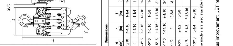
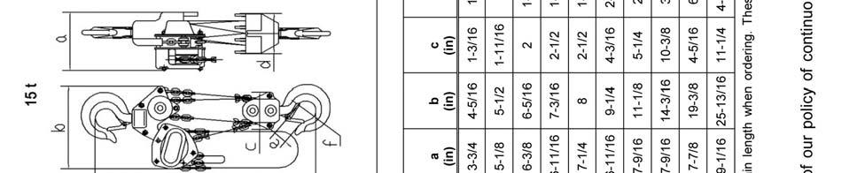
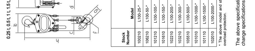
5 4.0 Specifications 5


6 5.0 Using the Chain Hoist 5.1 Prior to Operation 1. Support for the hoist may be hook, clevis pin, trolley, or beam clamp. Whatever method of suspension is chosen, the support components must be rated equal to, or greater than the capacity of the chain hoist. 2. If the chain hoist has not been used for an extended period of time, check for proper operation before putting into service. 3. The brake mechanism must be kept clean and free from dirt, water, and oil. Never allow oil to penetrate the brake mechanism. Always keep your chain hoist clean and store in a clean, dry location. 4. Although oiling the chain is not mandatory, a light coat of 30-weight oil applied periodically to the chain will create easier operation and prolong the life of the chain. 5. Check the chain for damage and elongation. Replace damaged chain before using the chain hoist. The load chain supplied with your JET chain hoist is designed, manufactured, and tested for proper fit and durability. Over a period of time, the chain may need to be replaced. For your own safety, use factory replacement chain only. Use of other than factory replacement chain may cause serious injury and/or damage to the hoist. Figure 1 6. The top and bottom hooks on your JET chain hoist are designed to open to warn of an overload. Both top and bottom hooks for 0.5 to 5 ton hoists have two indicator points (A, Figure 1) cast into the hook for measurement. Refer to Table 2 (page 13) to determine if a hook needs to be replaced. Hooks for 10- and 20-ton hoists do not have indicator points. Measurements are made at the jaw opening (B, Figure 1). 7. It is important to check top and bottom hooks for proper opening. If the safety latch no longer contacts the hook opening, replace the hook. Never side load the top or bottom hook; this practice is dangerous and could lead to serious injury. 8. If the vertical angle at the neck of the bottom or top hook reaches 10, replace the hook (see Figure 2). Figure 2


. 6.")

 clockwise.")
7 5.2 Hooking the Load 1. Secure the upper hook. 2. Place the bottom hook securely into the object to be lifted. 3. Place ropes or chain in the center of the bottom hook, making sure the safety latch is secure. Never load the hook in front of the safety latch. See Figure Avoid lifting one load with two hoists. If this is unavoidable, apply equal weight to both hoists and use hoists with the proper lift capacity. Capacity of each hoist must be equal to the total load to be lifted. 5. Check that the chain is not twisted at the bottom hook. All welds should face the same direction (Figure 4). 6. For hoists with two or more falls of chain, make sure the bottom hook is not turned over. This may cause the chain to twist. Figure 3 Figure Raising the Load To raise the load, pull the right side of the hand chain (A, Figure 5) clockwise. To lower the load, pull the left side of the hand chain (B, Figure 5) counterclockwise. Important: Make sure the hoist has an adequate length of load chain to raise or lower the load in a safe manner. Do not attempt to lower the hoist beyond its limit. Figure 5 7
8 6.0 Hand Chain Cutting and Installing To cut the hand chain in order to increase or shorten: To change the length of the hand chain, the chain must be cut and links added to increase the overall length or links removed to decrease the length. This is done as follows: 1. Insert one link lengthwise into the vise (Figure 6). Be sure that the side opposite the weld lies completely below the surface of the vise jaw (about 1/3 of a link). This prevents nicking or cutting the lower part of the link. Figure 6 2. Using a hack saw, cut through the upper part of the link at the weld. 3. Loosen the link, reposition the link vertically at the edge of the vise with the level of the cut above the vise jaw (Figure 7). 4. Tighten the vise jaw. Figure 7 5. Using an adjustable wrench, twist the link horizontally from front to back. (Figure 8) Open just far enough to insert (or remove) a second chain link. Note: Chain length is now ready to lengthen or shorten. 6. Insert or remove the second end link at the opening in the first end link. 7. Using an adjustable wrench, twist the link horizontally until the link is in the original closed position. See Figure 9. Do not push the link inward from the curved ends. This will distort the link. Check that the link is closed and free of twist. Figure 8 8. If installing entire new chain, insert the end of the hand chain into the groove at the top of the hand chain wheel (see Figure 10). Rotate the hand chain wheel and pull the chain through. 9. Re-weld the link at the cut. 10. Grind off excess on the weld so that it is smooth. Figure 9 8

9 7.0 Load Chain and Bottom Hook 7.1 Load Chain Inspection (all models) Over time, the load chain will wear or elongate. This can cause damage to the hoist, breakage, or non-engagement of the load sheave. Do not operate the hoist with a twisted, kinked or damaged load chain. Do not splice the load chain. Check the chain for excessive wear or stretch. Failure to comply may cause serious injury. 1. Test the hoist under load in both the lifting and lowering directions, observing the operation of chain and sprockets. Chain should feed smoothly into and away from the sprockets. 7.3 Attaching Load Chain to Load Chain Sprocket (all models) Install the new load chain onto the load chain sprocket as follows, referring to Fig. 10: 1. Position the load chain sprocket by rotating the hand chain wheel so that the wide and narrow grooves show. 2. Insert the load chain into the sprocket grooves so that the chain will wind up and back over the sprocket. Welds must face away from the sprocket. 3. Rotate the hand chain wheel so that the load chain falls six to eight inches at the back of the sprocket. 2. If the chain binds, jumps, or is noisy, make sure it is clean and properly lubricated. If the trouble persists, inspect the chain and mating parts for wear, distortion, or other damage. 3. Clean the chain before inspection. Examine for gouges, nicks, weld splatter, corrosion, and distorted links. Slacken the chain and move adjacent links to one side, looking for wear at the contact points. If you see wear or suspect stretching, measure the chain as follows: Select an unworn, unstretched length of chain (i.e. at the slack end). Suspend the chain vertically under tension and, using a caliper type gauge, measure the outside length of several links about 12 to 24 inches. Measure the same number of links in used sections and calculate the percentage of the increase in length. 4. If the length of used chain exceeds 2-1/2 percent of the unused chain, replace the chain. (See Load Limits on page 13 for specific link measurements.) Figure 10 Referring to Figure 11: 4. Insert one end of the chain link (B) into the chain anchor (D). 5. Insert the chain anchor pin (C) through the chain anchor (D) and chain link (B) and secure with the cotter pin (A). Do not add to the load chain. Replace the entire chain. Failure to comply may cause serious injury. 7.2 Load Chain Removal (all models) Remove the old load chain as follows while referring to Figure 11: 1. Remove the cotter pin (A) and the chain anchor pin (C) on the chain anchor (D), allowing the end of the chain to fall free. 2. Pull the hand chain (Fig. 5) until the load chain is completely removed from the gear assembly. Figure 11 Continue with Load Chain and Bottom Hook Installation on the following page, proceeding to the section that applies to your hoist: 1/2- to 2-Ton hoists, 3- to 5-Ton hoists, or 10- to 20-Ton Hoists. 9
10 7.4 Load Chain and Bottom Hook Installation The following procedure assumes that the load chain has been attached to the chain anchor (A, Figure 12) and fed through the load chain sprocket as described in the previous section. This section completes the load chain and bottom hook installation. 7.5 Chain Installation: 0.5- to 2-Ton Hoists Referring to Figure 12: 1. Remove the lock nut and bolt from the lower hook (D). 2. Insert the last chain link (C) into the lower hook slot. A B C D 3. Re-insert the bolt through the lower hook slot and chain link. 4. Re-attach the lock nut to the bolt and tighten. 0.5 to 2 Ton Figure Chain Installation: 3- to 5-Ton Hoists Referring to Figure 13: 1. After installing the load chain into the load chain sprocket (B), run the remaining chain through your hand to remove any twist. The last link of the chain must be in the same direction as the first. If not, cut off the last link. E 2. Insert the last link into the pulley of the lower hook (C). 3. Pull the load chain through and up from the underside of the pulley (C, D). A 4. Remove the cotter pin and chain anchor pin in the upper hook slot (E). C D 5. Insert the last link into the upper hook slot. 6. Check that the load chain is not twisted. B 7. Re-position the chain anchor pin back through the upper hook slot and the last chain link and secure with the cotter pin. 3 to 5 Ton Figure 13 10
11 7.7 Chain Installation: 10- to 20-Ton Hoists Referring to Figure 14: 1. After installing the load chain into the load chain sprocket (B), run the remaining chain through your hand to remove any twist. The last link of the chain must be in the same direction as the first. If not, cut off the last link. 2. Insert the last link into the left side pulley of the lower hook (C). 3. Pull the load chain through and up from the underside of the pulley (C, D). G 4. Insert the last link into the right hand pulley of the upper hook, moving the chain up, then around and down (D, E). Check that the load chain is not twisted and welds face away from the pulley. 5. Insert the last link into the right side pulley of the lower hook, pulling around, then up from the underside of the pulley (E, F). Check that the load chain is not twisted and welds face away from the pulley. 6. Remove the cotter pin and chain anchor pin in the upper hook slot (G). 7. Insert the last link into the upper hook slot. A B C D F E 8. Check that the load chain is not twisted. Re-position the chain anchor pin back through the upper hook slot and the last chain link and secure with the cotter pin. 10 Ton Figure Overload Protection Some models of the L-100 Hoist have overload protection in the form of a slip clutch (these are identified by WO in the model number). The slip clutch is effective at 160% +/-20% of the rated hoist capacity. The slip clutch will allow the hand chain pulley to move without lifting the load, if the load is too heavy for the hoist. The slip clutch has been pre-adjusted at the factory and should not require any adjustment by the user. If future adjustment or repair to the slip clutch should ever be needed, this must be done by qualified personnel. 11
12 9.0 Inspection and Maintenance Read and follow ANSI Inspection and Maintenance Instructions. Know the meaning of Frequent Inspection, Periodic Inspection, Normal Service, Heavy Service, and Severe Service. It is the customer s responsibility to understand and follow all ANSI and JET inspection and maintenance instructions. All repairs and adjustments are to be performed by trained and experienced personnel using procedures that are approved for the hoist system being serviced. Failure to comply may cause serious injury. All safety related deficiencies discovered in the inspection are to be corrected before the hoist is to be placed back into service. Failure to comply may cause serious injury. Check for internal damage whenever external damage has occurred. Failure to comply may cause serious injury. 1. Clean hoist after each use and oil lightly. NOTE: Do not get oil on brake system. 2. Do not drop or drag the hoist. 3. Store the hoist in a clean and dry environment. 4. While not mandatory, periodically oiling the chain with SAE 30 oil will increase its life. 5. Leave all repairs and adjustments of internal parts to qualified repair personnel. 6. Inspect the load chain and the lower hook after lifting a maximum weight load. 7. This hoist uses special alloy hoisting chain and does not interchange with any other manufacturer. All replacement chain must be purchased from your JET distributor or from JET directly by calling Check and inspect the brake system frequently. 9. Annually, the hoist should be disassembled, inspected, and cleaned by trained and experienced personnel only. Contact a JET authorized service center by calling your dealer or visiting our web site at jettools.com. 10. After servicing, test the hoist with no load, then test the hoist with a load. 12

13 10.0 Load Limits 10.1 Load Chain Capacity 5 Links Normal 5 Links Limit 0.25 ton " 0.5 ton " 1 ton " 1.5 ton " 2 ton " 3 ton " 5 ton " 10 ton " 15 ton " 20 ton " Table 1 Carefully inspect the entire load chain. As illustrated in Figure 15, measure five consecutive links with callipers to measure the length. Check every three feet and especially where excessive wear is indicated. Any load chain that shows noticeable deformation or heat influence must be replaced with a new one. Never extend load chain by welding a second piece to the original. Figure Hooks (Top & Bottom) Capacity A A B B Norm Limit Norm Limit 0.25 ton ton 1.36" 1.44" ton 1.77" 1.88" ton 1.86" 1.97" ton 2.05" 2.17" ton 2.45" 2.60" ton 3.06" 3.24" ton " 2.67" 15 ton ton Table 2 See Figure 16. Replace the hook when the A measurement is wider than A Limit in the table above. Never heat-treat the hook or attach anything to the hook by welding. B Figure 16 A 13
14 11.0 Troubleshooting JET Manual Chain Hoists Symptom Possible Cause Correction 1 Hoist will not move in either direction. Hoist will not lift load, or lifts with great difficulty. Hoist will not lower load, or lowers with great difficulty. Load drifts downward while suspended. Load chain jumps, or makes excessive noise. Hand chain wheel is jammed, worn, or damaged. Hand chain slips over wheel. Inspect and clean hand chain and hand chain wheel. Replace if worn or damaged. Check hand chain wheel for damage or worn cogs. Replace if needed. Load sheave or load chain is jammed. Inspect and clean. Check for chain link deformation. Replace elements if needed. Oil load chain for optimal performance. Load gear/spur gears jammed due to obstruction or damage. Bearing failure. Load too heavy for hoist. (models with overload protection 2 ): Slip clutch overload protection has been triggered due to excess load capacity. Load chain is binding. Load sheave is jammed. Ratchet disc teeth, pawls or pawl springs worn or damaged. Bearing failure. Load chain is binding due to obstruction, damage or wear. Brake/ratchet disc not releasing due to obstruction or damage. Load beyond capacity of hoist. Ratchet disc teeth, pawls or pawl springs worn or damaged. Brake disc(s) worn or dirty. Load chain is dirty or dry. Load chain kinked or twisted. Inspect, clean, and re-grease gears. Replace if worn or damaged. Contact JET service center for disassembly and replacement of bearings. Use a hoist with proper capacity for load. Disengage overload to reset hoist (see instruction manual). Only lift loads within hoist capacity. Inspect hoist elements for damage after overload has occurred. Inspect and clean load chain, load sheave, and stripper. Make sure chain is not twisted. Oil chain for optimal performance. Replace elements if deformation or other damage is found. Inspect and clean. Replace load sheave if damaged or excessively worn. Inspect elements and replace if needed. Contact JET service center for disassembly and replacement of bearings. Inspect and clean load chain and load sheave. Keep load chain lightly oiled. Replace chain if damaged or worn. Inspect and clean ratchet and pawl assemblies. Use properly rated hoist for load. Inspect elements and replace if needed. Inspect brake disc(s) for wear or damage. Consult thickness tolerances in manual, replace if needed. Inspect and clean load chain and load sheave. Oil chain for optimum performance. Remove twists in chain. Load chain is worn or deformed, or otherwise damaged. Chain catching in load sheave. Replace chain (use JET-authorized chain only). Inspect and clean chain and sheave. Check for chain deformations. Hook latch not closing. Latch is bent or broken. Replace latch. Hook is deformed preventing proper latch operation. Replace hook assembly. 1 Some corrections may need to be performed by a JET authorized service center. 2 Identified by WO in model number. 14
15 12.0 Timing Marks for Gear Replacement If the gears on the L-100 hoist need replacement or removal for any reason, make sure they are reinstalled correctly. Figure 17 shows the proper orientation of the timing marks when meshing the gears. Figure Replacement Parts Replacement parts are listed on the following pages. To order parts or reach our service department, call , Monday through Friday (see our website for business hours, Having the Model Number and Serial Number of your machine available when you call will allow us to serve you quickly and accurately. Non-proprietary parts, such as fasteners, can be found at local hardware stores, or may be ordered from JET. Some parts are shown for reference only, and may not be available individually. 15
16 L-100 Chain Hoist Parts Breakdown 16
17 Parts List: L Chain Hoist (0.25 Ton) Parts listed under each assembly are parts that make up that assembly (sold as an assembly only). Index No. Part No. Description Size Qty 1... L Top Hook Assembly Top Hook Safety Latch Double Spring Socket Head Cap Screw... M4x Lock Nut... M Top Hook Holder Rivet... 4x14 mm L Safety Latch Assembly Safety Latch Double Spring Socket Head Cap Screw... M4x Lock Nut... M L Top Hook Shaft L Split Pin x20 mm L Bottom Hook Assembly Bottom Hook Safety Latch Double Spring Socket Head Cap Screw... M4x Lock Nut... M Rivet... 5x20 mm L Bottom Hook Shaft F Lock Nut (Black Oxide)... M L G... Hand Wheel Cover Assembly Hand Wheel Cover Hand Chain Guide A... L A... Warning Label L Wheel Stopper... M L Wheel Washer L Hand Chain specify length... 3x15 mm L Hand Chain Connecting Link L Hand Chain Wheel L... L100-25WO-14L... Overload Limiter Assembly (used on overload protection model) Overload Limiter Knob Brake Disc Hand Chain Wheel Bushing in Hand Chain Wheel Disc Spring Plate Disc Spring Disc Spring Stopper Lock Nut L Snap Ring... 5 mm L Pawl L Pawl Spring L Ratchet Disc Assembly Ratchet Disc Ratchet Bushing L Disc Hub L Wheel Side Plate Assembly Wheel Side Plate Pawl Pin Brake Cover Double Seal Ball Bearing... d25xd42x9 mm L Double Seal Ball Bearing... d20xd37x9 mm A... L A... Double Seal Ball Bearing... d25xd42x9 mm B... L B... Double Seal Ball Bearing... d6xd15x5 mm
18 Parts List: L Chain Hoist (0.25 Ton) Index No. Part No. Description Size Qty L Gear Side Plate Assembly Gear Side Plate Bushing Double Seal Ball Bearing... d25xd42x9 mm L Load Gear L Drive Shaft L G... Gear Case Assembly Gear Case Bushing Double Seal Ball Bearing... d10xd22x6 mm F Lock Washer (Black Oxide)... M A... F Lock Washer (Black Oxide)... M F Lock Nut (Black Oxide)... M A... F Lock Nut (Black Oxide)... M L Rivet... 2x4 mm LM Name Plate, L LM Name Plate, L with overload L Spur Gear Assembly Spur Gear Pinion Gear L Load Sheave A... L A... C-Clip x2 mm B... L B... Needle Bearing HK d12xd16x8 mm L Guide Roller L Stripper L Chain Anchor Plate L Chain Anchor Pin L Split Pin... 2x12 mm L Load Chain specify length... 4x12 mm L Snap Ring mm L G... Dust Cover L100-WT... Warning Tag (not shown) Note: When ordering replacement chain (Index #12, #37), specify length. 18
19 Parts List: L Chain Hoist (0.5 Ton) Parts listed under each assembly are parts that make up that assembly (sold as an assembly only). Index No. Part No. Description Size Qty 1... L Top Hook Assembly Top Hook Safety Latch Double Spring Socket Head Cap Screw... M4x Lock Nut... M Top Hook Holder Rivet... 5x20 mm L Safety Latch Assembly Safety Latch Double Spring Socket Head Cap Screw... M4x Lock Nut... M L Top Hook Shaft L Split Pin... 2x20 mm L Bottom Hook Assembly Bottom Hook Safety Latch Double Spring Socket Head Cap Screw... M4x Lock Nut... M Rivet... 5x20 mm L Bottom Hook Shaft F Lock Nut... M L G... Hand Wheel Cover Assembly Hand Wheel Cover Hand Chain Guide A... L A... Warning Label L Wheel Stopper... M L Wheel Washer L Hand Chain specify length x22 mm L Hand Chain Connecting Link L Hand Chain Wheel L... L100-50WO-14-1L... Overload Limiter Assembly (used on overload protection model) Overload Limiter Knob Brake Disc Hand Chain Wheel Bushing in Hand Chain Wheel Disc Spring Plate Disc Spring Disc Spring Stopper Lock Nut L Snap Ring... 7 mm L Pawl L Pawl Spring L Ratchet Disc Assembly Ratchet Disc Ratchet Bushing L Disc Hub L Wheel Side Plate Assembly Wheel Side Plate Stay Bolt Pawl Pin Brake Cover Double Seal Ball Bearing... d30xd47x9 mm L Double Seal Ball Bearing... d30xd47x9 mm A... L A... Double Seal Ball Bearing... d25xd42x9 mm B... L B... Double Seal Ball Bearing... d10xd22x6 mm
20 Parts List: L Chain Hoist (0.5 Ton) Index No. Part No. Description Size Qty L Gear Side Plate Assembly Gear Side Plate Bushing Double Seal Ball Bearing... d25x42x9 mm L Load Gear L Drive Shaft L G... Gear Case Assembly Gear Case Bushing Double Seal Bearing... 10dx22Dx6 mm F Lock Washer... M A... F Lock Washer... M F Lock Nut... M A... F Lock Nut... M L Rivet... 3x5 mm LM Name Plate, L LM Name Plate, L with overload L Spur Gear Assembly Spur Gear Pinion Gear L Load Sheave A... L A... C-Clip mm B... L B... Needle Bearing... d14xd21x12 mm L Guide Roller L Stripper L Chain Anchor Plate L Chain Anchor Pin L Split Pin... 2x12 mm L Load Chain specify length... 5x15 mm L Snap Ring mm L G... Dust Cover L100-WT... Warning Tag (not shown) Note: When ordering replacement chain (Index #12, #37), specify length. 20
21 Parts List L Chain Hoist (1 Ton) Parts listed under each assembly are parts that make up that assembly (sold as an assembly only). Index No. Part No. Description Size Qty 1... L Top Hook Assembly Top Hook Safety Latch Double Spring Socket Head Cap Screw... M4x Lock Nut... M Top Hook Holder Rivet... 5x20 mm L Safety Latch Assembly Safety Latch Double Spring Socket Head Cap Screw... M4x Lock Nut... M L Top Hook Shaft L Split Pin x20 mm L Bottom Hook Assembly Bottom Hook Safety Latch Double Spring Socket Head Cap Screw... M4x Lock Nut... M Rivet... 5x20 mm L Bottom Hook Shaft F Lock Nut... M L G... Hand Wheel Cover Assembly Hand Wheel Cover Hand Chain Guide A... L A... Warning Label L Wheel Stopper... M L Wheel Washer L Hand Chain specify length... 5x25 mm L Hand Chain Connecting Link L Hand Chain Wheel L... L WO-14-1L.. Overload Limiter Assembly (used on overload protection model) Overload Limiter Knob Brake Disc Hand Chain Wheel Bushing in Hand Chain Wheel Disc Spring Plate Disc Spring Disc Spring Stopper Lock Nut L Snap Ring mm L Pawl L Pawl Spring L Ratchet Disc Assembly Ratchet Disc Ratchet Bushing L Disc Hub L Wheel Side Plate Assembly Wheel Side Plate Stay Bolt Pawl Pin Brake Cover Double Seal Ball Bearing... d30xd55x13 mm L Double Seal Ball Bearing... d30xd55x13 mm A... L A... Double Seal Ball Bearing... d25xd47x12 mm B... L B... Double Seal Ball Bearing... d10xd30x9 mm
22 Parts List: L Chain Hoist (1 Ton) Index No. Part No. Description Size Qty L Gear Side Plate Assembly Gear Side Plate Bushing Double Seal Ball Bearing... d25xd47x12 mm L Load Gear L Drive Shaft L G... Gear Case Assembly Gear Case Bushing Double Seal Bearing... d10xd30x9 mm F Lock Washer... M A... F Lock Washer... M F Lock Nut... M A... F Lock Nut... M L Rivet... 3x6 mm LM Name Plate, L LM Name Plate, L with overload L Spur Gear Assembly Spur Gear Pinion Gear L Load Sheave A... L A... C-Clip mm B... L B... Needle Bearing... 1d4xD21x12 mm L Guide Roller L Stripper L Chain Anchor Plate L Chain Anchor Pin L Split Pin... 2x15 mm L Load Chain specify length x19 mm L Snap Ring mm L G... Dust Cover L100-WT... Warning Tag (not shown) Note: When ordering replacement chain (Index #12, #37), specify length. 22
23 Parts List L Chain Hoist (1.5 Ton) Parts listed under each assembly are parts that make up that assembly (sold as an assembly only). Index No. Part No. Description Size Qty 1... L Top Hook Assembly Top Hook Safety Latch Double Spring Socket Head Cap Screw... M5x Lock Nut... M Top Hook Holder Rivet... 6x24 mm L Safety Latch Assembly Safety Latch Double Spring Socket Head Cap Screw... M5x Lock Nut... M L Top Hook Shaft L Split Pin x20 mm L Bottom Hook Assembly Bottom Hook Safety Latch Double Spring Socket Head Cap Screw... M5x Lock Nut... M Rivet... 6x24 mm L Bottom Hook Shaft F Lock Nut... M L G... Hand Wheel Cover Assembly Hand Wheel Cover Hand Chain Guide A... L A... Warning Label L Wheel Stopper... M L Wheel Washer L Hand Chain specify length... 5x25 mm L Hand Chain Connecting Link L Hand Chain Wheel L... L WO-14-1L.. Overload Limiter Assembly (used on overload protection model) Overload Limiter Knob Brake Disc Hand Chain Wheel Bushing in Hand Chain Wheel Disc Spring Plate Disc Spring Disc Spring Stopper Lock Nut L Snap Ring mm L Pawl L Pawl Spring L Ratchet Disc Assembly Ratchet Disc Ratchet Bushing L Disc Hub L Wheel Side Plate Assembly Wheel Side Plate Stay Bolt Pawl Pin Brake Cover Double Seal Ball Bearing... d30xd55x13 mm L Double Seal Ball Bearing... d30xd55x13 mm A... L Double Seal Ball Bearing... d30xd55x13 mm B... L B... Double Seal Ball Bearing... d10xd30x9 mm
24 Parts List: L Chain Hoist (1.5 Ton) Index No. Part No. Description Size Qty L Gear Side Plate Assembly Gear Side Plate Bushing Double Seal Ball Bearing... d30xd55x13 mm L Load Gear L Drive Shaft L G... Gear Case Assembly Gear Case Bushing Double Seal Bearing... d10xd30x9 mm F Lock Washer... M A... F Lock Washer... M F Lock Nut... M A... F Lock Nut... M L Rivet... 3x6 mm LM Name Plate, L LM Name Plate, L with overload L Spur Gear Assembly Spur Gear Pinion Gear L Load Sheave A... L A... C-Clip mm B... L B... Needle Bearing... d14xd21x12 mm L Guide Roller L Stripper L Chain Anchor Plate L Chain Anchor Pin L Split Pin... 2x15 mm L Load Chain specify length x21 mm L Snap Ring mm L G... Dust Cover L100-WT... Warning Tag (not shown) Note: When ordering replacement chain (Index #12, #37), specify length. 24
25 Parts List L Chain Hoist (2 Ton) Parts listed under each assembly are parts that make up that assembly (sold as an assembly only). Index No. Part No. Description Size Qty 1... L Top Hook Assembly Top Hook Safety Latch Double Spring Socket Head Cap Screw... M5x Lock Nut... M Top Hook Holder Rivet... 6x24 mm L Safety Latch Assembly Safety Latch Double Spring Socket Head Cap Screw... M5x Lock Nut... M L Top Hook Shaft L Split Pin x20 mm L Bottom Hook Assembly Bottom Hook Safety Latch Double Spring Socket Head Cap Screw... M5x Lock Nut... M Rivet... 6x24 mm L Bottom Hook Shaft F Lock Nut... M L G... Hand Wheel Cover Assembly Hand Wheel Cover Hand Chain Guide A... L A... Warning Label L Wheel Stopper... M L Wheel Washer L Hand Chain specify length... 5x25 mm L Hand Chain Connecting Link L Hand Chain Wheel L... L WO-14-1L.. Overload Limiter Assembly (used on overload protection model) Overload Limiter Knob Brake Disc Hand Chain Wheel Bushing in Hand Chain Wheel Disc Spring Plate Disc Spring Disc Spring Stopper Lock Nut L Snap Ring mm L Pawl L Pawl Spring L Ratchet Disc Assembly Ratchet Disc Ratchet Bushing L Disc Hub L Wheel Side Plate Assembly Wheel Side Plate Stay Bolt Pawl Pin Brake Cover Double Seal Ball Bearing... d35xd62x14 mm L Double Seal Ball Bearing... d35xd62x14 mm A... L Double Seal Ball Bearing... d30xd55x13 mm B... L B... Double Seal Ball Bearing... d12xd32x10 mm
26 Parts List L Chain Hoist (2 Ton) Index No. Part No. Description Size Qty L Gear Side Plate Assembly Gear Side Plate Bushing Double Seal Ball Bearing... d30xd55x13 mm L Load Gear L Drive Shaft L G... Gear Case Assembly Gear Case Bushing Double Seal Bearing... 12x32x10 mm F Lock Washer... M A... F Lock Washer... M F Lock Nut... M A... F Lock Nut... M L Rivet... 3x6 mm LM Name Plate, L LM Name Plate, L with overload L Spur Gear Assembly Spur Gear Pinion Gear L Load Sheave A... L A... C-Clip mm B... L B... Needle Bearing... 17x42x15 mm L Guide Roller L Stripper L Chain Anchor Plate L Chain Anchor Pin L Split Pin... 2x15 mm L Load Chain specify length... 8x24 mm L Snap Ring mm L G... Dust Cover L100-WT... Warning Tag (not shown) Note: When ordering replacement chain (Index #12, #37), specify length. 26
27 Parts List L Chain Hoist (3.0 Ton) Parts listed under each assembly are parts that make up that assembly (sold as an assembly only). Index No. Part No. Description Size Qty 1... L Top Hook Assembly Top Hook Safety Latch Double Spring Socket Head Cap Screw... M5x Lock Nut... M Top Hook Holder Rivet... 10x L Safety Latch Assembly Safety Latch Double Spring Socket Head Cap Screw... M5x Lock Nut... M L Top Hook Shaft L Split Pin x20 mm L Bottom Hook Assembly Bottom Hook Safety Latch Double Spring Socket Head Cap Screw... M5x Lock Nut... M Idle Shaft Idle Sheave Socket Head Cap Screw... M8x Lock Nut... M Lock Nut... M Lock Washer... M Bottom Hook Holder L G... Hand Wheel Cover Assembly Hand Wheel Cover Hand Chain Guide A... L A... Warning Label L Wheel Stopper... M L Wheel Washer L Hand Chain specify length... 5x25 mm L Hand Chain Connecting Link L Hand Chain Wheel L... L WO-14-1L.. Overload Limiter Assembly (used on overload protection model) Overload Limiter Knob Brake Disc Hand Chain Wheel Bushing in Hand Chain Wheel Disc Spring Plate Disc Spring Disc Spring Stopper Lock Nut L Snap Ring mm L Pawl L Pawl Spring L Ratchet Disc Assembly Ratchet Disc Ratchet Bushing L Disc Hub L Wheel Side Plate Assembly Wheel Side Plate Stay Bolt Pawl Pin Brake Cover Double Seal Ball Bearing... d30xd55x13 mm
28 Parts List: L Chain Hoist (3.0 Ton) Index No. Part No. Description Size Qty L Double Seal Ball Bearing... d30xd55x13 mm A... L Double Seal Ball Bearing... d30xd55x13 mm B... L B... Double Seal Ball Bearing... d10xd30x9 mm L Gear Side Plate Assembly Gear Side Plate Bushing Double Seal Ball Bearing... d30xd55x13 mm L Load Gear L Drive Shaft L G... Gear Case Assembly Gear Case Bushing Double Seal Bearing... d10xd30x9 mm F Lock Washer... M A... F Lock Washer... M F Lock Nut... M A... F Lock Nut... M L Rivet... 3x6 mm LM Name Plate, L LM Name Plate, L with overload L Spur Gear Assembly Spur Gear Pinion Gear L Load Sheave A... L A... C-Clip mm B... L B... Needle Bearing... 14x21x12 mm L Guide Roller L Stripper L Chain Anchor Plate L Chain Anchor Pin L Split Pin... 2x15 mm L Load Chain specify length x21 mm L Top Hook Pin F Lock Nut... M F Socket Head Cap Screw... M8x F Lock Nut... M L Idle Shaft L Idle Sheave L Snap Ring mm L G... Dust Cover L100-WT... Warning Tag (not shown) Note: When ordering replacement chain (Index #12, #37), specify length. 28
29 Parts List L Chain Hoist (5 Ton) Parts listed under each assembly are parts that make up that assembly (sold as an assembly only). Index No. Part No. Description Size Qty 1... L Top Hook Assembly Top Hook Safety Latch Double Spring Socket Head Cap Screw... M5x Lock Nut... M Top Hook Holder Rivet... 10x32 mm L Safety Latch Assembly Safety Latch Double Spring Socket Head Cap Screw... M5x Lock Nut... M L Top Hook Shaft L Split Pin x22 mm L Bottom Hook Assembly Bottom Hook Safety Latch Double Spring Socket Head Cap Screw... M5x Lock Nut... M Idle Shaft Idle Sheave Socket Head Cap Screw... M10x Lock Nut... M Bottom Hook Holder L G... Hand Wheel Cover Assembly Hand Wheel Cover Hand Chain Guide A... L A... Warning Label L Wheel Stopper... M L Wheel Washer L Hand Chain specify length... 5x25 mm L Hand Chain Connecting Link L Hand Chain Wheel L... L WO-14-1L.. Overload Limiter Assembly Overload Limiter Knob Brake Disc Hand Chain Wheel Bushing in Hand Chain Wheel Disc Spring Plate Disc Spring Disc Spring Stopper Lock Nut L Snap Ring mm L Pawl L Pawl Spring L Ratchet Disc Assembly Ratchet Disc Ratchet Bushing L Disc Hub L Wheel Side Plate Assembly Wheel Side Plate Stay Bolt Pawl Pin Brake Cover Double Seal Ball Bearing... d35xd62x14 mm L Double Seal Ball Bearing... d35xd62x14 mm
Operating Instructions and Parts Manual L-100 Series Hand Chain Hoists
 Operating Instructions and Parts Manual L-100 Series Hand Chain Hoists For L100-200 serial no. 15070001 and higher For L100-300 serial no. 15070043 and higher For L100-1500 serial no. 15070088 and higher
Operating Instructions and Parts Manual Lever Operated Chain Hoist JLH Series
 Operating Instructions and Parts Manual Lever Operated Chain Hoist JLH Series 1 Ton model shown JET 427 New Sanford Road LaVergne, Tennessee 37086 Part No. M-275050 Ph.: 800-274-6848 Revision H3 07/2018
LX1 Maintenance Manual for Model LX1B. Table of Contents 1. GENERAL DISASSEMBLY, ASSEMBLY AND ADJUSTMENT COMPONENTS...
 KTI KITO Technical Information LX1 Maintenance Manual for Model LX1B LX1-1.1.2 1 / 14 Edition: D 03.06 Table of Contents 1. GENERAL...2 2. DISASSEMBLY, ASSEMBLY AND ADJUSTMENT...2 3. COMPONENTS...3 4.
Product Parts Information. Lever Chain Hoists. KL Series. Save These Instructions. Form Edition 2 December Ingersoll-Rand
 Product Parts Information Lever Chain Hoists KL Series (Dwg MHP3278) Save These Instructions R Form 48489009 Edition 2 December 2013 2013 Ingersoll-Rand Only allow Ingersoll Rand trained technicians to
Operating Instructions and Parts Manual 3/4, 1-1/2, and 3 Ton Grip Pullers Models JG-75A, JG-150A, JG-300A
 Operating Instructions and Parts Manual 3/4, 1-1/2, and 3 Ton Grip Pullers Models JG-75A, JG-150A, JG-300A Model JG-75A shown JET 427 New Sanford Road LaVergne, Tennessee 37086 Part No. M-286575 Ph.: 800-274-6848
Operating Instructions and Parts Manual SLT-1100 Jumbo Scissor Lift Table
 Operating Instructions and Parts Manual SLT-1100 Jumbo Scissor Lift Table JET 427 New Sanford Road LaVergne, Tennessee 37086 Part No. M-140780 Ph.: 800-274-6848 Revision B1 05/2014 www.jettools.com Copyright
Tapping Screw (W/Flange) 46 Cord Armor 47 Tube (D) 48 Cord. 45 Cord Clip. Tapping Screw (W/Flange) 10 Gear Cover Ass'y. 12 Socket (B) Ass'y
 46 Cord Armor 47 Tube (D) 48 Cord. 45 Cord Clip. Tapping Screw (W/Flange) 10 Gear Cover Ass'y. 12 Socket (B) Ass'y") W8VB The exploded assembly drawing should be used only for authoized service center. W8VB Item No. Part time 1 Magnetic Hex. Socket 2 Sub Stopper 3 O-Ring (S-16) 4 Locator (A) 5 Lock Sleeve (A) 6 O-Ring
W8VB The exploded assembly drawing should be used only for authoized service center. W8VB Item No. Part time 1 Magnetic Hex. Socket 2 Sub Stopper 3 O-Ring (S-16) 4 Locator (A) 5 Lock Sleeve (A) 6 O-Ring
VARIABLE SPEED WOOD LATHE
 MODEL MC1100B VARIABLE SPEED WOOD LATHE INSTRUCTION MANUAL Please read and fully understand the instructions in this manual before operation. Keep this manual safe for future reference. Version: 2015.02.02
MANUAL PLASTIC STRAPPING TOOL MODEL P404
 OPERATION MANUAL / SPARE PARTS LIST MANUAL PLASTIC STRAPPING TOOL MODEL P404 43.0404.02 43040402.en/MAS/ 12.05 INDEX PAGE 1 SAFETY INSTRUCTIONS 2 2 TECHNICAL DATA 3 3 OPERATION ELEMENTS 4 4 ADJUSTMENT
12 Slip Roll. Model Assembly & Operating Instructions
 12 Slip Roll Model 36698 Assembly & Operating Instructions Diagrams within this manual may not be drawn proportionally. Due to continuing improvements, actual product may differ slightly from the product
Operating Instructions and Parts Manual Folding Hydraulic Crane Model: JFHC-200X
 This Manual is Bookmarked Operating Instructions and Parts Manual Folding Hydraulic Crane Model: JFHC-200X WMH TOOL GROUP 2420 Vantage Drive Elgin, Illinois 60123 Part No. M-106206K Ph.: 800-274-6848 Revision
Pow-R-Feed Systems Service Manual
 Pow-R-Feed Systems Service Manual Important Safety Instructions Please read this manual carefully and follow its instructions. Improper use or failure to follow these instructions could result in serious
 GENERAL OPERATIONAL PRECAUTIONS WARNING! When using electric tools, basic safety precautions should always be followed to reduce the risk of fire, electric shock and personal injury, including the following.
Spring Loaded All Season Roll-Up Doors
 Spring Loaded All Season Roll-Up Doors STAND-OFF MOUNTING METHOD INSTALLATION INSTRUCTIONS READ THIS FIRST Carefully examine the crate(s) for damage before opening. If the carton is damaged, immediately
MANUAL SEALLESS STEEL STRAPPING TOOL MODEL A332
 OPERATION MANUAL / SPARE PARTS LIST MANUAL SEALLESS STEEL STRAPPING TOOL MODEL A332 13.2250.01 INDEX PAGE 1 SAFETY INSTRUCTIONS 2 2 WARRANTY CONDITIONS AND LIABILITY 3 3 APPROPRIATE USE 3 4 TECNICAL DATA
CONTENTS PRECAUTIONS BEFORE STARTING OPERATION PREPARATION FOR OPERATION CAUTIONS ON USE OPERATION
 CONTENTS PRECAUTIONS BEFORE STARTING OPERATION ------------------------------------- 1 PREPARATION FOR OPERATION 1. Adjustment of needle bar stop position ---------------------------------------------------------
Sales and Service
 OPERATION MANUAL / SPARE PARTS LIST MANUAL SEALLESS STEEL STRAPPING TOOL MODEL A333 13.2370.01 INDEX PAGE 1 SAFETY INSTRUCTIONS 2 2 WARRANTY CONDITIONS AND LIABILITY 3 3 APPROPRIATE USE 3 4 TECNICAL DATA
GENERAL OPERATIONAL PRECAUTIONS PRECAUTIONS ON USING CUT-OFF MACHINE
 GENERAL OPERATIONAL PRECAUTIONS WARNING! When using electric tools, basic safety precautions should always be followed to reduce the risk of fire, electric shock and personal injury, including the following.
Model Numbers: P/N Date TPS-200 POLE SAW ATT TPS-200. Supplier To The Outdoor Power Equipment Industry
 Model Numbers: TPS-200 POLE SAW ATT TTACHMENT P/N 28577 Date 05-04-01 TPS-200 Supplier To The Outdoor Power Equipment Industry 1. Introduction It is important that you read and understand your TANAKA brush
CAUTION! This manual contains important information for the correct installation, operation and maintenance of the equipment described herein.
 CAUTION! This manual contains important information for the correct installation, operation and maintenance of the equipment described herein. All persons involved in such installation, operation, and
Rolling Curtain door Manual
 Rolling Curtain door Manual Installation Maintenance parts Model 944 PHONE 800 448 8979 FAX 800 236 8722 website www.tracrite.com EMAIL tr@tracrite.com ADDRESS 216 Wilburn Road Sun Prairie, WI 53590 This
Safety clamps, inc. Operation, Maintenance and Repair Manual for. Model HBC. Home of the big Bite Lifting Clamp
 Safety clamps, inc. Home of the big Bite Lifting Clamp Operation, Maintenance and Repair Manual for Model HBC Products manufactured by Safety Clamps, Inc. meet and/or exceed ANSI/ASME B30.20 standards
MANUAL SEALLESS STEEL STRAPPING TOOL MODEL A335
 OPERATION MANUAL / SPARE PARTS LIST MANUAL SEALLESS STEEL STRAPPING TOOL MODEL A335 13.2810.01 INDEX PAGE 1 SAFETY INSTRUCTIONS 2 2 WARRANTY CONDITIONS AND LIABILITY 3 3 APPROPRIATE USE 3 4 TECNICAL DATA
12 SHEAR, PRESS BRAKE &SLIPROLL
 12 SHEAR, PRESS BRAKE &SLIPROLL OPERATION MANUAL SPECIFICATION Cpacity: Roller : Die set sizes: Weight: 1mm thick (20gauge), 305 mm (12 ) width 38mm(1-1/2 ) 101.6mm(4 ), 76.2mm(3 ), 50.8mm (x2)[2 9x2]],
ULTRA CUTTER MINI SAW
 ULTRA CUTTER MINI SAW OPERATORS INSTRUCTION MANUAL Per OSHA 1926.503 it is the machine owner s responsibility to ensure that all workers using this Ultra Cutter Mini Saw are thoroughly trained in its use
VARIABLE SPEED WOOD LATHE. Model DB900 INSTRUCTION MANUAL
 VARIABLE SPEED WOOD LATHE Model DB900 INSTRUCTION MANUAL 1007 TABLE OF CONTENTS SECTION...PAGE Technical data.. 1 General safety rules....1-3 Specific safety rules for wood lathe.....3 Electrical information.4
MODEL 83 Pail Handler
 MORSE MFG. CO., INC. 727 West Manlius Street P.O. Box 518 East Syracuse, NY 13057-0518 Phone: 315-437-8475 Fax: 315-437-1029 Email: service@morsemfgco.com Website: www.morsemfgco.com COPYRIGHT 2005 MORSE
ROTARY HAMMER OWNER S MANUAL
 ROTARY HAMMER OWNER S MANUAL WARNING: Read carefully and understand all ASSEMBLY AND OPERATION INSTRUCTIONS before operating. Failure to follow the safety rules and other basic safety precautions may result
1. Turn off or disconnect power to unit (machine). 2. Push IN the release bar on the quick change base plate. Locking latch will pivot downward.
. 2. Push IN the release bar on the quick change base plate. Locking latch will pivot downward.") Figure 1 Miniature Quick Change Applicators, of the end feed type, are designed to crimp end feed strip terminals to prestripped wires. Each applicator is set up to accept the strip form of certain specific
Figure 1 Miniature Quick Change Applicators, of the end feed type, are designed to crimp end feed strip terminals to prestripped wires. Each applicator is set up to accept the strip form of certain specific
RATCHET CABLE CUTTER
 OPERATION, SERVICE AND PARTS INSTRUCTION MANUAL 764 RATCHET CABLE CUTTER Read and understand this material before operating or servicing this equipment. Failure to understand how to safely operate this
PHG-1000X. Owner s Manual HOME GYM
 HOME GYM Owner s Manual WWW.BODYSOLID.COM THERE IS A RISK ASSUMED BY INDIVIDUALS WHO USE THIS TYPE OF EQUIPMENT. TO MINIMIZE RISK, YOU MUST FOLLOW THESE RULES:! " # $ % & ' ( ) * + ' (, ' " -. *, * ) )
Repair manual. Fifth-wheel coupling JSK 38/50
 Repair manual Fifth-wheel coupling JSK 38/5 ZDE 199 3 12 E 6/212 1 Foreword Table of contents Page Fifth wheel couplings are connecting parts that must comply with very high safety requirements and must
N. 15th Street, Middlesboro, KY FLIP TARP DUMP BODY INSTALLATION INSTRUCTIONS
 1-800-248-7717 1002 N. 15th Street, Middlesboro, KY 40965 FLIP TARP DUMP BODY INSTALLATION INSTRUCTIONS Congratulations on your purchase of a Mountain Flip Tarp Dump Body tarping system. With tarping systems
400A 40113V, 401A 40120V, & 401AL 40120VL ALUMINUM VERTICAL 4000 LB LIFT INCLUDES SCREW LEG ASSEMBLY INSTRUCTIONS
 12/11/07 PAGE 1 OF 12 400A 40113V, 401A 40120V, & 401AL 40120VL ALUMINUM VERTICAL 4000 LB LIFT INCLUDES SCREW LEG ASSEMBLY INSTRUCTIONS Thank you for purchasing our product! *Please read these instructions
WARNING! Read and understand the entire instruction manual before attempting set-up or operation of this machine!
 ! WARNING! Read and understand the entire instruction manual before attempting set-up or operation of this machine! 1. This machine is designed and intended for use by properly trained and experienced
Astro-Physics Inc. 400QMD Lubrication/Maintenance Guide
 Astro-Physics Inc. 400QMD Lubrication/Maintenance Guide The following guidelines should be followed to lubricate the three main parts of the 400QMD mount. The QMD stands for Quartz Micro-Drive controller.
Crestline Dampening System. Installation Instructions. Ryobi 2700, 2800, 3200, 3200E Itek 950, 960, 975 Parent. X /98 Rev-A
 Crestline Dampening System Installation Instructions Ryobi 2700, 2800, 3200, 3200E Itek 950, 960, 975 Parent X88-30 3/98 Rev-A GENERAL INFORMATION ATTENTION CRESTLINE DAMPENER OWNER! Accel Graphic Systems
Operating Instructions and Parts Manual HN-16T Hand Notcher
 Operating Instructions and Parts Manual HN-16T Hand Notcher JET 427 New Sanford Road LaVergne, Tennessee 37086 Part No. M-756016 Ph.: 800-274-6848 Revision B1 08/2018 www.jettools.com Copyright 2015 JET
12mm (Max) 6mm (Max) 82mm (Max) 12mm (Max) 6mm (Max)
 6mm (Max) 82mm (Max) 12mm (Max) 6mm (Max)") 1 1 2 2 3 3 82mm (Max) 12mm (Max) 12mm (Max) 6mm (Max) 4 4 5 6 8 6mm (Max) 0.5 0mm 1 5 6 7 7 8 9 9 A = B 10 11 12 D B 1 13 14 15 0 C A D E 16 17 18 F G D B N H J G I K 19 A 20 G L 21 C K 1mm L M 1mm 22
1 1 2 2 3 3 82mm (Max) 12mm (Max) 12mm (Max) 6mm (Max) 4 4 5 6 8 6mm (Max) 0.5 0mm 1 5 6 7 7 8 9 9 A = B 10 11 12 D B 1 13 14 15 0 C A D E 16 17 18 F G D B N H J G I K 19 A 20 G L 21 C K 1mm L M 1mm 22
Instructions for Stone Cutting Machine
 Technical data Kg. Instructions for Stone Cutting Machine SCM600 3HP 2800rpm IP55 SCM800 3HP 2800rpm IP55 SCM1000 2800rpm IP55 SCM1200 2800rpm IP55 L=600 B=85(165) L=800 B=85(175) 500x510 0 or 45 600lt/h
Operating Instructions and Parts Manual SR-1650M Slip Roll
 Operating Instructions and Parts Manual SR-1650M Slip Roll WALTER MEIER (Manufacturing) Inc. 427 New Sanford Road LaVergne, Tennessee 37086 Part No. M-756050 Ph.: 800-274-6848 Revision A 12/2010 www.waltermeier.com
Fifth-wheel coupling JSK 38/50
 Repair manual Fifth-wheel coupling JSK 38/5 ZDE 199 3 12 E 6/25 1 LT SK38C-3 English RevA Foreword Table of contents Page Fifth wheel couplings are connecting parts that must comply with very high safety
Heavy Duty Mechanic s Kit
 Heavy Duty Mechanic s Kit 00 Safety Warning Read all instructions and safety warnings prior to operation. Failure to do so could result in equipment damage, personal injury or even death. CAUTION 00: FAILURE
Cut-Off Machine CC 14SF. Read through carefully and understand these instructions before use. Handling instructions
 Cut-Off Machine CC 14SF Read through carefully and understand these instructions before use. Handling instructions GENERAL OPERATIONAL PRES WARNING! When using electric tools, basic safety precautions
Spring Loaded SCREEN-PRO. All Season Roll-Up Doors IN-JAMB MOUNTING METHOD INSTALLATION INSTRUCTIONS READ THIS FIRST
 Spring Loaded SCREEN-PRO All Season Roll-Up Doors IN-JAMB MOUNTING METHOD INSTALLATION INSTRUCTIONS READ THIS FIRST Carefully examine the crate(s) for damage before opening. If the carton is damaged, immediately
DYNATRAC BALL JOINT REBUILD INSTRUCTIONS V4.0
 DYNATRAC PRODUCTS 2007-2016 4X4 JEEP JK HEAVY DUTY BALL JOINT JP44-2X3050-C DYNATRAC BALL JOINT REBUILD INSTRUCTIONS V4.0 WARNING: Improper use or installation of this product can cause major failures
20 TON HyDRAULIC SHOP PRESS with GRID GUARD 06/2015 INSTRUCTION MANUAL MODEL: KHP-20T-GG COPYRIGHT 2015 ALL RIGHTS RESERVED BY KING CANADA TOOLS INC.
 06/2015 20 TON HyDRAULIC SHOP PRESS with GRID GUARD MODEL: KHP-20T-GG INSTRUCTION MANUAL COPYRIGHT 2015 ALL RIGHTS RESERVED BY KING CANADA TOOLS INC. warranty INFORMATION 2-yEAR LIMITED WARRANTY FOR THIS
Rev B C-RING TOOL VA0375 ½ in. OPERATING MANUAL
 Rev B 4-30-0 C-RING TOOL VA0375 ½ in. OPERATING MANUAL Operational Instructions for Vertex C-Ring Tool VA0375 Vertex Fasteners is committed to providing our customers with world-class customer service
Assembly Instructions and Parts Manual JPSF-1 Fence and JPSR Rail Set #
 Assembly Instructions and Parts Manual JPSF-1 Fence and JPSR Rail Set #1002493 JET 427 New Sanford Road LaVergne, Tennessee 37086 Part No. M-708482 Ph.: 800-274-6848 Revision C3 02/2014 www.jettools.com
Operating Instructions and Parts Manual Manual Pinch Roll Bender Model MPR-10HV
 Operating Instructions and Parts Manual Manual Pinch Roll Bender Model MPR-10HV JET 427 New Sanford Road LaVergne, Tennessee 37086 Part No. M-754430 Ph.: 800-274-6848 Edition 1 09/2016 www.jettools.com
RESIDENTIAL MOTORIZED STORAGE UNIT
 BY V-BRO PRODUCTS RESIDENTIAL MOTORIZED STORAGE UNIT Model: GGR220 INSTALLATION AND OPERATING INSTRUCTIONS Distributed Exclusively by V-BRO PRODUCTS For technical questions and replacement parts, please
All Terrain Vise # 10010
 Operating Instructions & Service Parts Manual All Terrain Vise # 10010 Record purchase information for quick reference: WILTON 427 New Sanford Road LaVergne, Tennessee 37086 Ph.: 800-274-6848 www.wiltontools.com
PROSTEER BALL JOINT REBUILD INSTRUCTIONS V1.0
 DYNATRAC PRODUCTS 2003-2010 4X4 DODGE 2500/3500 HEAVY DUTY BALL JOINT PROSTEER BALL JOINT REBUILD INSTRUCTIONS V1.0 WARNING: Improper use or installation of this product can cause major failures that could
18 GAUGE ELECTRIC METAL SHEAR
 241-9895 18 GAUGE ELECTRIC METAL SHEAR Operator s Manual SAVE THIS MANUAL You will need this manual for safety instructions, operating procedures and warranty. Put it and the original sales receipt in
GENERAL OPERATIONAL PRECAUTIONS PRECAUTIONS ON USING DISC GRINDER
 GENERAL OPERATIONAL PRECAUTIONS WARNING! When using electric tools, basic safety precautions should always be followed to reduce the risk of fire, electric shock and personal injury, including the following.
Operating Instructions and Parts Manual Dual-Sided 16ga. Box and Pan Brake Model PBF-1650D
 Operating Instructions and Parts Manual Dual-Sided 16ga. Box and Pan Brake Model PBF-1650D JET 427 New Sanford Road LaVergne, Tennessee 37086 Part No. M-752130 Ph.: 800-274-6848 Edition 2 08/2018 www.jettools.com
Operating, Servicing, and Safety Manual Model " Foot Shear CAUTION: Read and Understand
 Operating, Servicing, and Safety Manual Model 3000 52" Foot Shear CAUTION: Read and Understand These Operating, Servicing, and Safety Instructions, Before Using This Machine. SAFETY The purpose of the
SHRINKER/STRETCHER SET Create radius bends and contours in sheet metal
 Owner s Manual & Safety Instructions Save This Manual Keep this manual for the safety warnings and precautions, assembly, operating, inspection, maintenance and cleaning procedures. Write the product s
Cam Handle Service Guide
 Cam Handle Service Guide Page 2. Introduction Page 3. Troubleshooting guide Page 4-5. Adjusting the clamp force Page 6-7. Disassembling, greasing and replacing components Page 8-9. Replacing the post bearings
YALE FIGURE 500 & 500R CLOSURE OPERATION AND MAINTENANCE INSTRUCTIONS
 YALE FIGURE 500 & 500R CLOSURE OPERATION AND MAINTENANCE INSTRUCTIONS IMPORTANT INFORMATION Note To Supervisor: Please share this information with your employees and make sure they have received training
ACREAGE SEEDER / PLANTER OWNER S MANUAL
 ACREAGE SEEDER / PLANTER OWNER S MANUAL WARNING: Read carefully and understand all ASSEMBLY AND OPERATION INSTRUCTIONS before operating. Failure to follow the safety rules and other basic safety precautions
Operating Instructions and Parts Manual SR-2024M and SR-2236M Slip Rolls
 Operating Instructions and Parts Manual SR-2024M and SR-2236M Slip Rolls JET 427 New Sanford Road LaVergne, Tennessee 37086 Part No. M-756020 Revision A1 05/2014 Copyright 2014 JET Warranty and Service
COMBINATION STRAPPING TOOL
 AM COMBINATION STRAPPING TOOL READ THESE INSTRUCTIONS CAREFULLY. FAILURE TO FOLLOW THESE INSTRUCTIONS CAN RESULT IN SEVERE PERSONAL INJURY. GENERAL SAFETY CONSIDERATIONS 1. STRAP BREAKAGE HAZARD. Improper
INSTALLATION INSTRUCTIONS
 INSTALLATION INSTRUCTIONS INSTALLATION INSTRUCTIONS THESE INSTRUCTIONS COVER THE INSTALLATION OF THE FOLLOWING REAR DOORS WITH OUTSIDE CABLES AND MAXIMUM SECURITY LOCK: 3/4" DryFreight 1-1/8" PolarGuard
Assembly Instructions and Parts Manual Taper Attachment for Bench Lathes Model TAK-13GH/BD
 Assembly Instructions and Parts Manual Taper Attachment for Bench Lathes Model TAK-13GH/BD JET 427 New Sanford Road LaVergne, Tennessee 37086 Part No. M-321442 Ph.: 800-274-6848 Revision B 03/2014 www.jettools.com
Tube Facing Tool.
 www.swagelok.com Tube Facing Tool This manual contains important information for the safe and effective operation of the Swagelok TF72 series tube facing tool. Users should read and understand its contents
WALK-BEHIND SPREADER 50 LB. CAPACITY Model 99623
 WALK-BEHIND SPREADER 50 LB. CAPACITY Model 99623 Assembly, Operating, and Maintenance Instructions Diagrams within this manual may not be drawn proportionally. Due to continuing improvements, actual product
Maintenance Information
 16601023 Edition 2 January 2014 Air Impact Wrench 2705P1 Maintenance Information Save These Instructions Product Safety Information WARNING Failure to observe the following warnings, and to avoid these
WEIGHT ADJUSTABLE ESPREE. Model 2ESP-WA-C48- Model 2ESP-WA-C60- 2ESP-WA Rev B 8/17 ASSEMBLY AND OPERATION
 WEIGHT ADJUSTABLE ESPREE PNEUMATIC TABLE BASE 2ESP-WA Rev B 8/17 Model 2ESP-WA-C48- Model 2ESP-WA-C60- = SLV, BLK or WHT ASSEMBLY AND OPERATION PARTS AND TOOLS PLEASE REVIEW these instructions before beginning
DYNATRAC BALL JOINT REBUILD INSTRUCTIONS V5.0
 DYNATRAC PRODUCTS 2007-2018 JEEP JK HEAVY DUTY BALL JOINT JP44-2X3050-C DYNATRAC BALL JOINT REBUILD INSTRUCTIONS V5.0 WARNING: Improper use or installation of this product can cause major failures that
Block and Ball Inspection Checklist
 Block and Ball Inspection Checklist 01/16 P/N 67688 Rev. 1 Page 2 of 8 Block and Ball Inspection Checklist The purpose for the inspection check list is to provide a quick reference for checking the integrity
Electric Skein Winder
 Electric Skein Winder Assembly and Use Package Contents 1 - Triangular Body (w/ motor) 1 - Cross Arm 1 - Left Foot (w/ yarn guide) 1 - Right Foot 1 - Adjustable Finger (w/ yarn clip) 3 - Adjustable Fingers
GENERAL OPERATIONAL PRECAUTIONS
 GENERAL OPERATIONAL PRECAUTIONS WARNING! When using electric tools, basic safety precautions should always be followed to reduce the risk of fire, electric shock and personal injury, including the following.
8-Ton Manual Splitter OWNER S MANUAL
 8-Ton Manual Splitter OWNER S MANUAL WARNING: Read carefully and understand all ASSEMBLY AND OPERATION INSTRUCTIONS before operating. Failure to follow the safety rules and other basic safety precautions
CONTENTS LOCATE AND IDENTIFY THE PARTS... WIND THE BOBBIN... PREPARE YOUR TOP THREAD... STITCH SELECTOR / STITCH LENGTH/STITCH WIDTH CONTROLS...
 SERVICE MANUAL SEWING MACHINE MODEL 385. 15208400 OCTOBER, 2003 CONTENTS LOCATE AND IDENTIFY THE PARTS... WIND THE BOBBIN... PREPARE YOUR TOP THREAD... STITCH SELECTOR / STITCH LENGTH/STITCH WIDTH CONTROLS...
Assembly Instructions and Parts Manual Taper Attachment for ZH Lathes
 Assembly Instructions and Parts Manual Taper Attachment for ZH Lathes JET 427 New Sanford Road LaVergne, Tennessee 37086 Part No. M-321293 Ph.: 800-274-6848 Rev B 08/2018 www.jettools.com Copyright 2017
Cut-Off Machine Model CC 14SE
 Cut-Off Machine Model CC 14SE Handling instructions NOTE: Before using this Electric Power Tool, carefully read through these HANDLING INSTRUCTIONS to ensure efficient, safe operation. It is recommended
Mechanical Actuators
 Mechanical Actuators Translating Ball Screw Actuators 1/2-Ton through 50-Ton Capacity Installation, Operation & Maintenance Instructions Publication Part No. SK-2373 CAUTION This manual contains important
Operating Instructions and Parts Manual 16 ga. x 100 in. Box and Pan Brake Model BPF-16100
 Operating Instructions and Parts Manual 16 ga. x 100 in. Box and Pan Brake Model BPF-16100 JET 427 New Sanford Road LaVergne, Tennessee 37086 Part No. M-754115 Ph.: 800-274-6848 Edition 3 08/2018 www.jettools.com
HOME GYM Owner s Manual
 HOME GYM Owner s Manual Content Content-------------------------------------------------------------1 Safety precautions----------------------------------------------------2 Assembly instruction-------------------------------------------------3-12
Installation Instructions
 Instructions Created by an: Suzuki Samurai, Sidekick, X90 Geo Tracker Off Road Universal Joint (SKU# SAX-UJOR) Instructions also apply to: SKU# SAX-UJOE, SDT-FY-9095, SAX-SY, STM-SL Installation Instructions
FOR PROFESSIONAL GARAGE DOOR INSTALLERS
 Composite Garage Doors Installation Instructions FOR PROFESSIONAL GARAGE DOOR INSTALLERS Tools required Screwdriver Claw Hammer Locking Pliers Power Drill Level with a 3/32" Drill Bit Utility Knife 9/16",
Operating Instructions and Parts Manual. 10 x 16 Horizontal Band Saw Models J-7020, J-7040
 Operating Instructions and Parts Manual 10 x 16 Horizontal Band Saw Models J-7020, J-7040 JET 427 New Sanford Road LaVergne, Tennessee 37086 Part No. M-414472 Ph.: 800-274-6848 Revision C2 03/2014 www.jettools.com
pneumatic c-ring tool
 pneumatic c-ring tool hc5 HC5 WARNINGS! Always read tool manual before operating tool. Always wear safety glasses when operating or while in the area where a tool is being used. When test cycling tool
H6400, H6400C1 & VSD6400 REVERSIBLE DRILLS
 SERVICE MANUAL H6400, H6400C1 & VSD6400 REVERSIBLE DRILLS Read and understand all of the instructions and safety information in this manual before operating or servicing this tool. 999 1801.3 REV 4 2001
Operating Instructions and Parts Manual Sliding Table Jig
 Operating Instructions and Parts Manual Sliding Table Jig WMH TOOL GROUP 2420 Vantage Drive Elgin, Illinois 60123 Part No. M-709695 Ph.: 800-274-6848 Revision A 04/04 www.wmhtoolgroup.com Copyright WMH
OWNER'S MANUAL TIE ROD, WALL & FLOOR MOUNTED JIBS. Model JIB-HC, JIB-LC, JIB-FM
 Vestil Manufacturing Company 999 N. Wayne Street, P.O. Box 507 Angola, IN 6703 USA Phone (60) 665-7586 Fax (60) 665-339 sales@vestil.com www.vestil.com Revised 09-0 A company dedicated to solving ergonomic
REPAIR INSTRUCTIONS. Cat. No Cat. No MILWAUKEE ELECTRIC TOOL CORPORATION. SDS Max Demolition Hammer. SDS Max Rotary Hammer
 Cat. No. 9-0 SDS Max Demolition Hammer Cat. No. -0 SDS Max Rotary Hammer MILWAUKEE ELECTRIC TOOL CORPORATION W. LISBON ROAD BROOKFIELD, WISCONSIN 00-0 8-9-0 d 000 8-9-0 d Special Tools Require Forcing
HD installation guide
 JANUS INTERNATIONAL 1 866 562 2580 www.janusintl.c o m 1950 1950HD installation guide RIGHT DRIVE END SHOWN LH OPPOSITE LEFT TENSION END SHOWN RH OPPOSITE PUSH-UP OPERATION 1950 1950HD SHOWN A rolling
SOKIII AND SOKIII XL
 RV INSTALLATION MANUAL SOKIII AND SOKIII XL SLIDEOUT COVER Read this manual before servicing this product. Failure to follow the instructions and safety precautions in this manual can result in personal
Operating Instructions and Parts Manual 10 x 14 Horizontal Mitering Band Saw Model MBS-1014W
 Operating Instructions and Parts Manual 10 x 14 Horizontal Mitering Band Saw Model MBS-1014W JET 427 New Sanford Road LaVergne, Tennessee 37086 Part No. M-414477 Ph.: 800-274-6848 Revision H1 01/2017 www.jettools.com
Operating Instructions and Parts Manual SLT-660F/1650 Scissor Lift Tables
 Operating Instructions and Parts Manual SLT-660F/1650 Scissor Lift Tables WALTER MEIER (Manufacturing) Inc. 427 New Sanford Road LaVergne, Tennessee 37086 Part No. M-140777 Ph.: 800-274-6848 Revision C
PLA144X. Owner s Manual LAT ROW STATION
 LAT ROW STATION Owner s Manual WWW.BODYSOLID.COM THERE IS A RISK ASSUMED BY INDIVIDUALS WHO USE THIS TYPE OF EQUIPMENT. TO MINIMIZE RISK, YOU MUST FOLLOW THESE RULES: Inspect equipment before each workout.
Operating Instructions and Parts Manual 72-inch Box and Pan Brakes Models BP-1272 and BP-1672
 Operating Instructions and Parts Manual 72-inch Box and Pan Brakes Models BP-1272 and BP-1672 JET 427 New Sanford Road LaVergne, Tennessee 37086 Part No. M-754125 Ph.: 800-274-6848 Edition 3 08/2018 www.jettools.com
EMB Manufacturing Inc Boomer Line St. Clements, On N0B 2M0 Canada Ph: (519) Fax: (519) P200
 Fax: (519) P200") BY EMB MFG INC. EMB Manufacturing Inc. 4144 Boomer Line St. Clements, On N0B 2M0 Canada Ph: (519) 699-9283 Fax: (519) 699-4146 www.embmfg.com Available: P210 Spare Pivoting Chainsaw Adaptor See page 6
BY EMB MFG INC. EMB Manufacturing Inc. 4144 Boomer Line St. Clements, On N0B 2M0 Canada Ph: (519) 699-9283 Fax: (519) 699-4146 www.embmfg.com Available: P210 Spare Pivoting Chainsaw Adaptor See page 6
MI MI OPERATING MANUAL
 MODEL NO.: MI-76100 MI-76150 OPERATING MANUAL RULES for SAFE OPERATION MAGNUM INDUSTRIAL MI-76100 and MI 76150 DRILL PRESSES To help ensure safe operation, please take a moment to learn the how to operate
Installation, Operating and Maintenance Instructions. Translating Ball Screw Actuators. 1/2 ton through 50 Ton. Publication Part No. SK-2373.
 Installation, Operating and Maintenance Instructions Translating Ball Screw Actuators 1/2 ton through 50 Ton Publication Part No. SK-2373 Caution This manual contains important information for the correct
ULTRA CUTTER PRO OPERATORS INSTRUCTION MANUAL. This manual covers all models 9, 11 and 13 HP
 ULTRA CUTTER PRO OPERATORS INSTRUCTION MANUAL This manual covers all models 9, 11 and 13 HP Per OSHA 1926.503 it is the machine owner s responsibility to ensure that all workers using this Ultra Cutter
PFT CABLE GYM INSTRUCTION MANUAL
 PFT CABLE GYM INSTRUCTION MANUAL QUESTION? As a quality home gym supplier we are committed to your complete satisfaction. If you have questions, or find missing or damaged parts, we will guarantee your
installation guide
 JANUS INTERNATIONAL 1 866 562 2580 w w w. j a n u s i n t l. c o m 2000 2500 3000 installation guide RIGHT DRIVE END SHOWN LH OPPOSITE LEFT TENSION END SHOWN RH OPPOSITE PUSH-UP OPERATION 2000 2500 3000