Operating Instructions and Parts Manual L-100 Series Hand Chain Hoists
|
|
|
- Corey Hicks
- 6 years ago
- Views:
Transcription


1 Operating Instructions and Parts Manual L-100 Series Hand Chain Hoists For L serial no and higher For L serial no and higher For L serial no and higher 1-ton model shown JET 427 New Sanford Road LaVergne, Tennessee Part No. M Ph.: Revision D 08/ Copyright 2015 JET
2 Warranty and Service JET warrants every product it sells against manufacturers defects. If one of our tools needs service or repair, please contact Technical Service by calling , 8AM to 5PM CST, Monday through Friday. Warranty Period The general warranty lasts for the time period specified in the literature included with your product or on the official JET branded website. JET products carry a limited warranty which varies in duration based upon the product. (See chart below) Accessories carry a limited warranty of one year from the date of receipt. Consumable items are defined as expendable parts or accessories expected to become inoperable within a reasonable amount of use and are covered by a 90 day limited warranty against manufacturer s defects. Who is Covered This warranty covers only the initial purchaser of the product from the date of delivery. What is Covered This warranty covers any defects in workmanship or materials subject to the limitations stated below. This warranty does not cover failures due directly or indirectly to misuse, abuse, negligence or accidents, normal wear-and-tear, improper repair, alterations or lack of maintenance. JET woodworking machinery is designed to be used with Wood. Use of these machines in the processing of metal, plastics, or other materials outside recommended guidelines may void the warranty. The exceptions are acrylics and other natural items that are made specifically for wood turning. Warranty Limitations Woodworking products with a Five Year Warranty that are used for commercial or industrial purposes default to a Two Year Warranty. Please contact Technical Service at for further clarification. How to Get Technical Support Please contact Technical Service by calling Please note that you will be asked to provide proof of initial purchase when calling. If a product requires further inspection, the Technical Service representative will explain and assist with any additional action needed. JET has Authorized Service Centers located throughout the United States. For the name of an Authorized Service Center in your area call or use the Service Center Locator on the JET website. More Information JET is constantly adding new products. For complete, up-to-date product information, check with your local distributor or visit the JET website. How State Law Applies This warranty gives you specific legal rights, subject to applicable state law. Limitations on This Warranty JET LIMITS ALL IMPLIED WARRANTIES TO THE PERIOD OF THE LIMITED WARRANTY FOR EACH PRODUCT. EXCEPT AS STATED HEREIN, ANY IMPLIED WARRANTIES OF MERCHANTABILITY AND FITNESS FOR A PARTICULAR PURPOSE ARE EXCLUDED. SOME STATES DO NOT ALLOW LIMITATIONS ON HOW LONG AN IMPLIED WARRANTY LASTS, SO THE ABOVE LIMITATION MAY NOT APPLY TO YOU. JET SHALL IN NO EVENT BE LIABLE FOR DEATH, INJURIES TO PERSONS OR PROPERTY, OR FOR INCIDENTAL, CONTINGENT, SPECIAL, OR CONSEQUENTIAL DAMAGES ARISING FROM THE USE OF OUR PRODUCTS. SOME STATES DO NOT ALLOW THE EXCLUSION OR LIMITATION OF INCIDENTAL OR CONSEQUENTIAL DAMAGES, SO THE ABOVE LIMITATION OR EXCLUSION MAY NOT APPLY TO YOU. JET sells through distributors only. The specifications listed in JET printed materials and on official JET website are given as general information and are not binding. JET reserves the right to effect at any time, without prior notice, those alterations to parts, fittings, and accessory equipment which they may deem necessary for any reason whatsoever. JET branded products are not sold in Canada by JPW Industries, Inc. Product Listing with Warranty Period 90 Days Parts; Consumable items 1 Year Motors; Machine Accessories 2 Year Metalworking Machinery; Electric Hoists, Electric Hoist Accessories; Woodworking Machinery used for industrial or commercial purposes 5 Year Woodworking Machinery Limited Lifetime JET Parallel clamps; VOLT Series Electric Hoists; Manual Hoists; Manual Hoist Accessories; Shop Tools; Warehouse & Dock products; Hand Tools; Air Tools NOTE: JET is a division of JPW Industries, Inc. References in this document to JET also apply to JPW Industries, Inc., or any of its successors in interest to the JET brand. 2
3 Table of Contents Warranty and Service... 2 Table of Contents... 3 Introduction... 3 Warning... 4 Specifications... 5 Using the Chain Hoist... 6 Prior to Operation... 6 Hooking the Load... 7 Raising the Load... 7 Hand Chain Cutting and Installing... 8 Load Chain and Bottom Hook... 9 Load Chain Inspection (all models)... 9 Load Chain Removal (all models)... 9 Load Chain and Bottom Hook Installation Chain Installation 0.5- to 2-Ton Hoists Chain Installation 3- to 5-Ton Hoists Chain Installation 10- to 20-Ton Hoists Overload Protection Inspection and Maintenance Load Limits Load Chain Hooks (Top & Bottom) Timing Marks for Gear Replacement Replacement Parts L-100 Chain Hoist Parts Breakdown Parts List: L Chain Hoist (0.25 Ton) Parts List: L Chain Hoist (0.5 Ton) Parts List L Chain Hoist (1 Ton) Parts List L Chain Hoist (1.5 Ton) Parts List L Chain Hoist (2 Ton) Parts List L Chain Hoist (3.0 Ton) Parts List L Chain Hoist (5 Ton) Parts List L Chain Hoist (10 Ton) Parts List L Chain Hoist (15 Ton) Parts List L Chain Hoist (20 Ton) Introduction This manual is provided by JET covering the safe operation and maintenance procedures for a JET Model L-100 Series Chain Hoist. This manual contains instructions on installation, safety precautions, general operating procedures, maintenance instructions and parts breakdown. This hoist has been designed and constructed to provide consistent, long-term operation if used in accordance with instructions set forth in this manual. If there are any questions or comments, please contact either your local supplier or JET. JET can also be reached at our web site: The L-100 Chain Hoist complies with ANSI/ASME B30.16 and HST-2 standards. 3
4 Warning 1. Read and understand the entire owner s manual before attempting assembly or operation. 2. Read and understand the warnings posted on the tool and in this manual. Failure to comply with all of these warnings may cause serious injury and/or damage to property. 3. Replace the warning labels if they become obscured or are missing. 4. Keep visitors a safe distance from the work area. Keep children away. 5. Give your work undivided attention. Looking around, carrying on a conversation and horse-play are careless acts that can result in serious injury. 6. This chain hoist is designed and intended for use by properly trained and experienced personnel only. If you are not familiar with the proper and safe operation of a chain hoist, do not use until proper training and knowledge have been obtained. 7. Do not use this chain hoist for other than its intended use. If used for other purposes, JET disclaims any real or implied warranty and holds itself harmless from any injury that may result from that use. 8. Do not use to lift people or loads over people. 9. Do not exceed the rated capacity of the chain hoist. 10. Do not use more than hand power to pull the hand chain. 11. Do not use the load chain as a sling; this may cause damage to the chain. 12. Always inspect the chain hoist for damage prior to use. If the chain hoist is damaged, do not use until it has been repaired or replaced. 13. Do not use more than one chain hoist to lift or move a load. If this is unavoidable, each chain hoist must have the same capacity as the load to be moved. 14. Never allow the load chain to set over sharp edges. All lifts must be made with straight chain that is free of obstacles. 15. If the hand chain is difficult to operate, then the load exceeds the capacity of the chain hoist. Select a chain hoist of larger capacity. 16. Do not use a chain hoist unless load is centered between top and bottom hooks. 17. Always take time to study the job to be performed and choose the safest method. Do not place yourself or other people in an unsafe position. 18. Leave all internal maintenance to a qualified JET Service Center. 19. Replace the chain with factory replacement chain only. Do not use any other type of chain. 20. Never use the chain hoist if either hook is stretched, deformed, or has a broken or missing safety latch. Always replace the safety latch and/or the hook before placing the chain hoist back into service. 21. Understand and follow all procedures as set forth in American National Standards titled Performance Standard for Hand Chain Manually Operated Chain Hoists. ANSI/ASME HST-2; and Overhead Hoists (Underhung), ANSI/ASME B These standards are available through the American Society of Mechanical Engineers, 345 East 47 th St., NY, NY ( Familiarize yourself with the following safety notices used in this manual: This means that if precautions are not heeded, it may result in minor injury and/or possible tool damage. even death. This means that if precautions are not heeded, it may result in serious injury or possibly 4
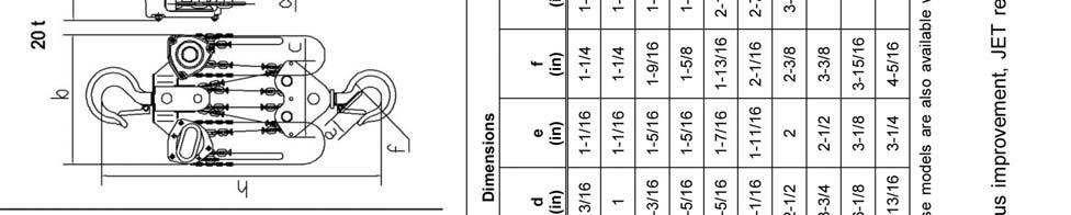
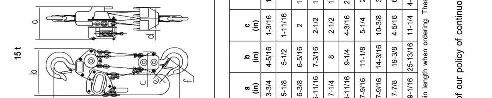
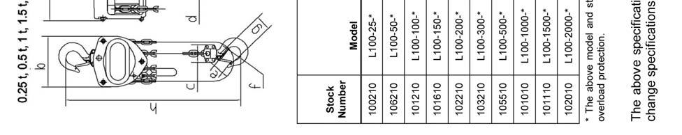
5 Specifications 5


6 Using the Chain Hoist Prior to Operation 1. Support for the hoist may be hook, clevis pin, trolley, or beam clamp. Whatever method of suspension is chosen, the support components must be rated equal to, or greater than the capacity of the chain hoist. 2. If the chain hoist has not been used for an extended period of time, check for proper operation before putting into service. 3. The brake mechanism must be kept clean and free from dirt, water, and oil. Never allow oil to penetrate the brake mechanism. Always keep your chain hoist clean and store in a clean, dry location. 4. Although oiling the chain is not mandatory, a light coat of 30-weight oil applied periodically to the chain will create easier operation and prolong the life of the chain. 5. Check the chain for damage and elongation. Replace damaged chain before using the chain hoist. The load chain supplied with your JET chain hoist is designed, manufactured, and tested for proper fit and durability. Over a period of time, the chain may need to be replaced. For your own safety, use factory replacement chain only. Use of other than factory replacement chain may cause serious injury and/or damage to the hoist. 6. The top and bottom hooks on your JET chain hoist are designed to open to warn of an overload. Both top and bottom hooks for 0.5 to 5 ton hoists have two indicator points (A, Figure 1) cast into the hook for measurement. Refer to Table 2 (page 13) to determine if a hook needs to be replaced. Hooks for 10- and 20-ton hoists do not have indicator points. Measurements are made at the jaw opening (B, Figure 1). 7. It is important to check top and bottom hooks for proper opening. If the safety latch no longer contacts the hook opening, replace the hook. Never side load the top or bottom hook; this practice is dangerous and could lead to serious injury. 8. If the vertical angle at the neck of the bottom or top hook reaches 10, replace the hook (see Figure 2). Figure 1 Figure 2 6


. 6.")

 clockwise.")
7 Hooking the Load 1. Secure the upper hook. 2. Place the bottom hook securely into the object to be lifted. 3. Place ropes or chain in the center of the bottom hook, making sure the safety latch is secure. Never load the hook in front of the safety latch. See Figure Avoid lifting one load with two hoists. If this is unavoidable, apply equal weight to both hoists and use hoists with the proper lift capacity. Capacity of each hoist must be equal to the total load to be lifted. 5. Check that the chain is not twisted at the bottom hook. All welds should face the same direction (Figure 4). 6. For hoists with two or more falls of chain, make sure the bottom hook is not turned over. This may cause the chain to twist. Figure 3 Raising the Load To raise the load, pull the right side of the hand chain (A, Figure 5) clockwise. To lower the load, pull the left side of the hand chain (B, Figure 5) counterclockwise. Important: Make sure the hoist has an adequate length of load chain to raise or lower the load in a safe manner. Do not attempt to lower the hoist beyond its limit. Figure 4 Figure 5 7
8 Hand Chain Cutting and Installing To cut the hand chain in order to increase or shorten: To change the length of the hand chain, the chain must be cut and links added to increase the overall length or links removed to decrease the length. This is done as follows: 1. Insert one link lengthwise into the vise (Figure 6). Be sure that the side opposite the weld lies completely below the surface of the vise jaw (about 1/3 of a link). This prevents nicking or cutting the lower part of the link. Figure 6 2. Using a hack saw, cut through the upper part of the link at the weld. 3. Loosen the link, reposition the link vertically at the edge of the vise with the level of the cut above the vise jaw (Figure 7). 4. Tighten the vise jaw. 5. Using an adjustable wrench, twist the link horizontally from front to back. (Figure 8) Open just far enough to insert (or remove) a second chain link. Figure 7 Note: Chain length is now ready to lengthen or shorten. 6. Insert or remove the second end link at the opening in the first end link. 7. Using an adjustable wrench, twist the link horizontally until the link is in the original closed position. See Figure 9. Do not push the link inward from the curved ends. This will distort the link. Check that the link is closed and free of twist. 8. If installing entire new chain, insert the end of the hand chain into the groove at the top of the hand chain wheel (see Figure 10). Rotate the hand chain wheel and pull the chain through. Figure 8 9. Re-weld the link at the cut. 10. Grind off excess on the weld so that it is smooth. Figure 9 8

9 Load Chain and Bottom Hook Load Chain Inspection (all models) Over time, the load chain will wear or elongate. This can cause damage to the hoist, breakage, or non-engagement of the load sheave. Do not operate the hoist with a twisted, kinked or damaged load chain. Do not splice the load chain. Check the chain for excessive wear or stretch. Failure to comply may cause serious injury. 1. Test the hoist under load in both the lifting and lowering directions, observing the operation of chain and sprockets. Chain should feed smoothly into and away from the sprockets. 2. If the chain binds, jumps, or is noisy, make sure it is clean and properly lubricated. If the trouble persists, inspect the chain and mating parts for wear, distortion, or other damage. 3. Clean the chain before inspection. Examine for gouges, nicks, weld splatter, corrosion, and distorted links. Slacken the chain and move adjacent links to one side, looking for wear at the contact points. If you see wear or suspect stretching, measure the chain as follows: Select an unworn, unstretched length of chain (i.e. at the slack end). Suspend the chain vertically under tension and, using a caliper type gauge, measure the outside length of several links about 12 to 24 inches. Measure the same number of links in used sections and calculate the percentage of the increase in length. 4. If the length of used chain exceeds 2-1/2 percent of the unused chain, replace the chain. (See Load Limits on page 13 for specific link measurements.) Attaching Load Chain to Load Chain Sprocket (all models) Install the new load chain onto the load chain sprocket as follows, referring to Fig. 10: 1. Position the load chain sprocket by rotating the hand chain wheel so that the wide and narrow grooves show. 2. Insert the load chain into the sprocket grooves so that the chain will wind up and back over the sprocket. Welds must face away from the sprocket. 3. Rotate the hand chain wheel so that the load chain falls six to eight inches at the back of the sprocket. Figure 10 Referring to Figure 11: 4. Insert one end of the chain link (B) into the chain anchor (D). 5. Insert the chain anchor pin (C) through the chain anchor (D) and chain link (B) and secure with the cotter pin (A). Do not add to the load chain. Replace the entire chain. Failure to comply may cause serious injury. Load Chain Removal (all models) Remove the old load chain as follows while referring to Figure 11: 1. Remove the cotter pin (A) and the chain anchor pin (C) on the chain anchor (D), allowing the end of the chain to fall free. 2. Pull the hand chain (Fig. 5) until the load chain is completely removed from the gear assembly. Figure 11 Continue with Load Chain and Bottom Hook Installation on the following page, proceeding to the section that applies to your hoist: 1/2- to 2-Ton hoists, 3- to 5-Ton hoists, or 10- to 20-Ton Hoists. 9
10 Load Chain and Bottom Hook Installation The following procedure assumes that the load chain has been attached to the chain anchor (A, Figure 12) and fed through the load chain sprocket as described in the previous section. This section completes the load chain and bottom hook installation. A Chain Installation 0.5- to 2-Ton Hoists Referring to Figure 12: 1. Remove the lock nut and bolt from the lower hook (D). B C D 2. Insert the last chain link (C) into the lower hook slot. 3. Re-insert the bolt through the lower hook slot and chain link. 4. Re-attach the lock nut to the bolt and tighten. 0.5 to 2 Ton Figure 12 Chain Installation 3- to 5-Ton Hoists Referring to Figure 13: 1. After installing the load chain into the load chain sprocket (B), run the remaining chain through your hand to remove any twist. The last link of the chain must be in the same direction as the first. If not, cut off the last link. E 2. Insert the last link into the pulley of the lower hook (C). 3. Pull the load chain through and up from the underside of the pulley (C, D). 4. Remove the cotter pin and chain anchor pin in the upper hook slot (E). A C D 5. Insert the last link into the upper hook slot. 6. Check that the load chain is not twisted. B 7. Re-position the chain anchor pin back through the upper hook slot and the last chain link and secure with the cotter pin. 3 to 5 Ton Figure 13 10
11 Chain Installation 10- to 20-Ton Hoists Referring to Figure 14: 1. After installing the load chain into the load chain sprocket (B), run the remaining chain through your hand to remove any twist. The last link of the chain must be in the same direction as the first. If not, cut off the last link. 2. Insert the last link into the left side pulley of the lower hook (C). 3. Pull the load chain through and up from the underside of the pulley (C, D). 4. Insert the last link into the right hand pulley of the upper hook, moving the chain up, then around and down (D, E). Check that the load chain is not twisted and welds face away from the pulley. 5. Insert the last link into the right side pulley of the lower hook, pulling around, then up from the underside of the pulley (E, F). Check that the load chain is not twisted and welds face away from the pulley. 6. Remove the cotter pin and chain anchor pin in the upper hook slot (G). 7. Insert the last link into the upper hook slot. 8. Check that the load chain is not twisted. Re-position the chain anchor pin back through the upper hook slot and the last chain link and secure with the cotter pin. A C D B F E G 10 Ton Figure 14 Overload Protection Some models of the L-100 Hoist have overload protection in the form of a slip clutch (these are identified by WO in the model number). The slip clutch is effective at 160% +/-20% of the rated hoist capacity. The slip clutch will allow the hand chain pulley to move without lifting the load, if the load is too heavy for the hoist. The slip clutch has been pre-adjusted at the factory and should not require any adjustment by the user. If future adjustment or repair to the slip clutch should ever be needed, this must be done by qualified personnel. 11
12 Inspection and Maintenance Read and follow ANSI Inspection and Maintenance Instructions. Know the meaning of Frequent Inspection, Periodic Inspection, Normal Service, Heavy Service, and Severe Service. It is the customer s responsibility to understand and follow all ANSI and JET inspection and maintenance instructions. All repairs and adjustments are to be performed by trained and experienced personnel using procedures that are approved for the hoist system being serviced. Failure to comply may cause serious injury. All safety related deficiencies discovered in the inspection are to be corrected before the hoist is to be placed back into service. Failure to comply may cause serious injury. Check for internal damage whenever external damage has occurred. Failure to comply may cause serious injury. 1. Clean hoist after each use and oil lightly. 2. Do not drop or drag the hoist. 3. Store the hoist in a clean and dry environment. 4. Chain oiling is not mandatory but will increase the life of the chain. 5. Leave all repairs and adjustments of internal parts to qualified repair personnel. 6. Inspect the load chain and the lower hook after lifting a maximum weight load. 7. This hoist uses special alloy hoisting chain and does not interchange with any other manufacturer. All replacement chain must be purchased from your JET distributor or from JET directly by calling Check and inspect the brake system frequently. 9. Annually, the hoist should be disassembled, inspected, and cleaned by trained and experienced personnel only. Contact a JET authorized service center by calling your dealer or visiting our web site at jettools.com. 10. After servicing, test the hoist with no load, then test the hoist with a load. 12

13 Load Limits Load Chain Capacity 5 Links Normal 5 Links Limit 0.25 ton " 0.5 ton " 1 ton " 1.5 ton " 2 ton " 3 ton " 5 ton " 10 ton " 15 ton " 20 ton " Table 1 Carefully inspect the entire load chain. As illustrated in Figure 15, measure five consecutive links with callipers to measure the length. Check every three feet and especially where excessive wear is indicated. Any load chain that shows noticeable deformation or heat influence must be replaced with a new one. Never extend load chain by welding a second piece to the original. Figure 15 Hooks (Top & Bottom) Capacity A A B B Norm Limit Norm Limit 0.25 ton ton 1.36" 1.44" ton 1.77" 1.88" ton 1.86" 1.97" ton 2.05" 2.17" ton 2.45" 2.60" ton 3.06" 3.24" ton " 2.67" 15 ton ton Table 2 See Figure 16. Replace the hook when the A measurement is wider than A Limit in the table above. Never heat-treat the hook or attach anything to the hook by welding. B Figure 16 A 13
14 Timing Marks for Gear Replacement If the gears on the L-100 hoist need replacement or removal for any reason, make sure they are reinstalled correctly. Figure 17 shows the proper orientation of the timing marks when meshing the gears. Figure 17 Replacement Parts Replacement parts are listed on the following pages. To order parts or reach our service department, call , Monday through Friday (see our website for business hours, Having the Model Number and Serial Number of your machine available when you call will allow us to serve you quickly and accurately. 14
15 L-100 Chain Hoist Parts Breakdown 15
16 Parts List: L Chain Hoist (0.25 Ton) Parts listed under each assembly are parts that make up that assembly (sold as an assembly only) L Top Hook Assembly Top Hook Socket Head Cap Screw... M4x Lock Nut... M Top Hook Holder Rivet... 4x14 mm L Safety Latch Assembly Safety Latch Double Spring Socket Head Cap Screw... M4x Lock Nut... M L Top Hook Shaft L Split Pin x20 mm L Bottom Hook Assembly Bottom Hook Socket Head Cap Screw... M4x Lock Nut... M Rivet... 5x20 mm L Bottom Hook Shaft F Lock Nut (Black Oxide)... M L G... Hand Wheel Cover Assembly Hand Wheel Cover Hand Chain Guide A... L A... Warning Label L Wheel Stopper... M L Wheel Washer L Hand Chain specify length... 3x15 mm L Hand Chain Connecting Link L Hand Chain Wheel L... L100-25WO-14L... Overload Limiter Assembly (used on overload protection model) Overload Limiter Knob Brake Disc Hand Chain Wheel Bushing in Hand Chain Wheel Disc Spring Plate Disc Spring Disc Spring Stopper Lock Nut L Snap Ring... 5 mm L Pawl L Pawl Spring L Ratchet Disc Assembly Ratchet Disc Ratchet Bushing L Disc Hub L Wheel Side Plate Assembly Wheel Side Plate Pawl Pin Brake Cover Double Seal Ball Bearing... d25xd42x9 mm L Double Seal Ball Bearing... d20xd37x9 mm A... L A... Double Seal Ball Bearing... d25xd42x9 mm B... L B... Double Seal Ball Bearing... d6xd15x5 mm
17 Parts List: L Chain Hoist (0.25 Ton) L Gear Side Plate Assembly Gear Side Plate Bushing Double Seal Ball Bearing... d25xd42x9 mm L Load Gear L Drive Shaft L G... Gear Case Assembly Gear Case Bushing Double Seal Ball Bearing... d10xd22x6 mm F Lock Washer (Black Oxide)... M A... F Lock Washer (Black Oxide)... M F Lock Nut (Black Oxide)... M A... F Lock Nut (Black Oxide)... M L Rivet... 2x4 mm LM Name Plate, L LM Name Plate, L with overload L Spur Gear Assembly Spur Gear Pinion Gear L Load Sheave A... L A... C-Clip x2 mm B... L B... Needle Bearing HK d12xd16x8 mm L Guide Roller L Stripper L Chain Anchor Plate L Chain Anchor Pin L Split Pin... 2x12 mm L Load Chain specify length... 4x12 mm L Snap Ring mm L G... Dust Cover L100-WT... Warning Tag (not shown) Note: When ordering replacement chain (Index #12, #37), specify length. 17
18 Parts List: L Chain Hoist (0.5 Ton) Parts listed under each assembly are parts that make up that assembly (sold as an assembly only) L Top Hook Assembly Top Hook Socket Head Cap Screw... M4x Lock Nut... M Top Hook Holder Rivet... 5x20 mm L Safety Latch Assembly Safety Latch Double Spring Socket Head Cap Screw... M4x Lock Nut... M L Top Hook Shaft L Split Pin... 2x20 mm L Bottom Hook Assembly Bottom Hook Socket Head Cap Screw... M4x Lock Nut... M Rivet... 5x20 mm L Bottom Hook Shaft F Lock Nut... M L G... Hand Wheel Cover Assembly Hand Wheel Cover Hand Chain Guide A... L A... Warning Label L Wheel Stopper... M L Wheel Washer L Hand Chain specify length x22 mm L Hand Chain Connecting Link L Hand Chain Wheel L... L100-50WO-14-1L... Overload Limiter Assembly (used on overload protection model) Overload Limiter Knob Brake Disc Hand Chain Wheel Bushing in Hand Chain Wheel Disc Spring Plate Disc Spring Disc Spring Stopper Lock Nut L Snap Ring... 7 mm L Pawl L Pawl Spring L Ratchet Disc Assembly Ratchet Disc Ratchet Bushing L Disc Hub L Wheel Side Plate Assembly Wheel Side Plate Stay Bolt Pawl Pin Brake Cover Double Seal Ball Bearing... d30xd47x9 mm L Double Seal Ball Bearing... d30xd47x9 mm A... L A... Double Seal Ball Bearing... d25xd42x9 mm B... L B... Double Seal Ball Bearing... d10xd22x6 mm
19 Parts List: L Chain Hoist (0.5 Ton) L Gear Side Plate Assembly Gear Side Plate Bushing Double Seal Ball Bearing... d25x42x9 mm L Load Gear L Drive Shaft L G... Gear Case Assembly Gear Case Bushing Double Seal Bearing... 10dx22Dx6 mm F Lock Washer... M A... F Lock Washer... M F Lock Nut... M A... F Lock Nut... M L Rivet... 3x5 mm LM Name Plate, L LM Name Plate, L with overload L Spur Gear Assembly Spur Gear Pinion Gear L Load Sheave A... L A... C-Clip mm B... L B... Needle Bearing... d14xd21x12 mm L Guide Roller L Stripper L Chain Anchor Plate L Chain Anchor Pin L Split Pin... 2x12 mm L Load Chain specify length... 5x15 mm L Snap Ring mm L G... Dust Cover L100-WT... Warning Tag (not shown) Note: When ordering replacement chain (Index #12, #37), specify length. 19
20 Parts List L Chain Hoist (1 Ton) Parts listed under each assembly are parts that make up that assembly (sold as an assembly only) L Top Hook Assembly Top Hook Socket Head Cap Screw... M4x Lock Nut... M Top Hook Holder Rivet... 5x20 mm L Safety Latch Assembly Safety Latch Double Spring Socket Head Cap Screw... M4x Lock Nut... M L Top Hook Shaft L Split Pin x20 mm L Bottom Hook Assembly Bottom Hook Socket Head Cap Screw... M4x Lock Nut... M Rivet... 5x20 mm L Bottom Hook Shaft F Lock Nut... M L G... Hand Wheel Cover Assembly Hand Wheel Cover Hand Chain Guide A... L A... Warning Label L Wheel Stopper... M L Wheel Washer L Hand Chain specify length... 5x25 mm L Hand Chain Connecting Link L Hand Chain Wheel L... L WO-14-1L.. Overload Limiter Assembly (used on overload protection model) Overload Limiter Knob Brake Disc Hand Chain Wheel Bushing in Hand Chain Wheel Disc Spring Plate Disc Spring Disc Spring Stopper Lock Nut L Snap Ring mm L Pawl L Pawl Spring L Ratchet Disc Assembly Ratchet Disc Ratchet Bushing L Disc Hub L Wheel Side Plate Assembly Wheel Side Plate Stay Bolt Pawl Pin Brake Cover Double Seal Ball Bearing... d30xd55x13 mm L Double Seal Ball Bearing... d30xd55x13 mm A... L A... Double Seal Ball Bearing... d25xd47x12 mm B... L B... Double Seal Ball Bearing... d10xd30x9 mm
21 Parts List: L Chain Hoist (1 Ton) L Gear Side Plate Assembly Gear Side Plate Bushing Double Seal Ball Bearing... d25xd47x12 mm L Load Gear L Drive Shaft L G... Gear Case Assembly Gear Case Bushing Double Seal Bearing... d10xd30x9 mm F Lock Washer... M A... F Lock Washer... M F Lock Nut... M A... F Lock Nut... M L Rivet... 3x6 mm LM Name Plate, L LM Name Plate, L with overload L Spur Gear Assembly Spur Gear Pinion Gear L Load Sheave A... L A... C-Clip mm B... L B... Needle Bearing... 1d4xD21x12 mm L Guide Roller L Stripper L Chain Anchor Plate L Chain Anchor Pin L Split Pin... 2x15 mm L Load Chain specify length x19 mm L Snap Ring mm L G... Dust Cover L100-WT... Warning Tag (not shown) Note: When ordering replacement chain (Index #12, #37), specify length. 21
22 Parts List L Chain Hoist (1.5 Ton) Parts listed under each assembly are parts that make up that assembly (sold as an assembly only) L Top Hook Assembly Top Hook Socket Head Cap Screw... M5x Lock Nut... M Top Hook Holder Rivet... 6x24 mm L Safety Latch Assembly Safety Latch Double Spring Socket Head Cap Screw... M5x Lock Nut... M L Top Hook Shaft L Split Pin x20 mm L Bottom Hook Assembly Bottom Hook Socket Head Cap Screw... M5x Lock Nut... M Rivet... 6x24 mm L Bottom Hook Shaft F Lock Nut... M L G... Hand Wheel Cover Assembly Hand Wheel Cover Hand Chain Guide A... L A... Warning Label L Wheel Stopper... M L Wheel Washer L Hand Chain specify length... 5x25 mm L Hand Chain Connecting Link L Hand Chain Wheel L... L WO-14-1L.. Overload Limiter Assembly (used on overload protection model) Overload Limiter Knob Brake Disc Hand Chain Wheel Bushing in Hand Chain Wheel Disc Spring Plate Disc Spring Disc Spring Stopper Lock Nut L Snap Ring mm L Pawl L Pawl Spring L Ratchet Disc Assembly Ratchet Disc Ratchet Bushing L Disc Hub L Wheel Side Plate Assembly Wheel Side Plate Stay Bolt Pawl Pin Brake Cover Double Seal Ball Bearing... d30xd55x13 mm L Double Seal Ball Bearing... d30xd55x13 mm A... L Double Seal Ball Bearing... d30xd55x13 mm B... L B... Double Seal Ball Bearing... d10xd30x9 mm
23 Parts List: L Chain Hoist (1.5 Ton) L Gear Side Plate Assembly Gear Side Plate Bushing Double Seal Ball Bearing... d30xd55x13 mm L Load Gear L Drive Shaft L G... Gear Case Assembly Gear Case Bushing Double Seal Bearing... d10xd30x9 mm F Lock Washer... M A... F Lock Washer... M F Lock Nut... M A... F Lock Nut... M L Rivet... 3x6 mm LM Name Plate, L LM Name Plate, L with overload L Spur Gear Assembly Spur Gear Pinion Gear L Load Sheave A... L A... C-Clip mm B... L B... Needle Bearing... d14xd21x12 mm L Guide Roller L Stripper L Chain Anchor Plate L Chain Anchor Pin L Split Pin... 2x15 mm L Load Chain specify length x21 mm L Snap Ring mm L G... Dust Cover L100-WT... Warning Tag (not shown) Note: When ordering replacement chain (Index #12, #37), specify length. 23
24 Parts List L Chain Hoist (2 Ton) Parts listed under each assembly are parts that make up that assembly (sold as an assembly only) L Top Hook Assembly Top Hook Socket Head Cap Screw... M5x Lock Nut... M Top Hook Holder Rivet... 6x24 mm L Safety Latch Assembly Safety Latch Double Spring Socket Head Cap Screw... M5x Lock Nut... M L Top Hook Shaft L Split Pin x20 mm L Bottom Hook Assembly Bottom Hook Socket Head Cap Screw... M5x Lock Nut... M Rivet... 6x24 mm L Bottom Hook Shaft F Lock Nut... M L G... Hand Wheel Cover Assembly Hand Wheel Cover Hand Chain Guide A... L A... Warning Label L Wheel Stopper... M L Wheel Washer L Hand Chain specify length... 5x25 mm L Hand Chain Connecting Link L Hand Chain Wheel L... L WO-14-1L.. Overload Limiter Assembly (used on overload protection model) Overload Limiter Knob Brake Disc Hand Chain Wheel Bushing in Hand Chain Wheel Disc Spring Plate Disc Spring Disc Spring Stopper Lock Nut L Snap Ring mm L Pawl L Pawl Spring L Ratchet Disc Assembly Ratchet Disc Ratchet Bushing L Disc Hub L Wheel Side Plate Assembly Wheel Side Plate Stay Bolt Pawl Pin Brake Cover Double Seal Ball Bearing... d35xd62x14 mm L Double Seal Ball Bearing... d35xd62x14 mm A... L Double Seal Ball Bearing... d30xd55x13 mm B... L B... Double Seal Ball Bearing... d12xd32x10 mm
25 Parts List L Chain Hoist (2 Ton) L Gear Side Plate Assembly Gear Side Plate Bushing Double Seal Ball Bearing... d30xd55x13 mm L Load Gear L Drive Shaft L G... Gear Case Assembly Gear Case Bushing Double Seal Bearing... 12x32x10 mm F Lock Washer... M A... F Lock Washer... M F Lock Nut... M A... F Lock Nut... M L Rivet... 3x6 mm LM Name Plate, L LM Name Plate, L with overload L Spur Gear Assembly Spur Gear Pinion Gear L Load Sheave A... L A... C-Clip mm B... L B... Needle Bearing... 17x42x15 mm L Guide Roller L Stripper L Chain Anchor Plate L Chain Anchor Pin L Split Pin... 2x15 mm L Load Chain specify length... 8x24 mm L Snap Ring mm L G... Dust Cover L100-WT... Warning Tag (not shown) Note: When ordering replacement chain (Index #12, #37), specify length. 25
26 Parts List L Chain Hoist (3.0 Ton) Parts listed under each assembly are parts that make up that assembly (sold as an assembly only) L Top Hook Assembly Top Hook Socket Head Cap Screw... M5x Lock Nut... M Top Hook Holder Rivet... 10x L Safety Latch Assembly Safety Latch Double Spring Socket Head Cap Screw... M5x Lock Nut... M L Top Hook Shaft L Split Pin x20 mm L Bottom Hook Assembly Bottom Hook Socket Head Cap Screw... M5x Lock Nut... M Idle Shaft Idle Sheave Socket Head Cap Screw... M8x Lock Nut... M Lock Nut... M Lock Washer... M Bottom Hook Holder L G... Hand Wheel Cover Assembly Hand Wheel Cover Hand Chain Guide A... L A... Warning Label L Wheel Stopper... M L Wheel Washer L Hand Chain specify length... 5x25 mm L Hand Chain Connecting Link L Hand Chain Wheel L... L WO-14-1L.. Overload Limiter Assembly (used on overload protection model) Overload Limiter Knob Brake Disc Hand Chain Wheel Bushing in Hand Chain Wheel Disc Spring Plate Disc Spring Disc Spring Stopper Lock Nut L Snap Ring mm L Pawl L Pawl Spring L Ratchet Disc Assembly Ratchet Disc Ratchet Bushing L Disc Hub L Wheel Side Plate Assembly Wheel Side Plate Stay Bolt Pawl Pin Brake Cover Double Seal Ball Bearing... d30xd55x13 mm
27 Parts List: L Chain Hoist (3.0 Ton) L Double Seal Ball Bearing... d30xd55x13 mm A... L Double Seal Ball Bearing... d30xd55x13 mm B... L B... Double Seal Ball Bearing... d10xd30x9 mm L Gear Side Plate Assembly Gear Side Plate Bushing Double Seal Ball Bearing... d30xd55x13 mm L Load Gear L Drive Shaft L G... Gear Case Assembly Gear Case Bushing Double Seal Bearing... d10xd30x9 mm F Lock Washer... M A... F Lock Washer... M F Lock Nut... M A... F Lock Nut... M L Rivet... 3x6 mm LM Name Plate, L LM Name Plate, L with overload L Spur Gear Assembly Spur Gear Pinion Gear L Load Sheave A... L A... C-Clip mm B... L B... Needle Bearing... 14x21x12 mm L Guide Roller L Stripper L Chain Anchor Plate L Chain Anchor Pin L Split Pin... 2x15 mm L Load Chain specify length x21 mm L Top Hook Pin F Lock Nut... M F Socket Head Cap Screw... M8x F Lock Nut... M L Idle Shaft L Idle Sheave L Snap Ring mm L G... Dust Cover L100-WT... Warning Tag (not shown) Note: When ordering replacement chain (Index #12, #37), specify length. 27
28 Parts List L Chain Hoist (5 Ton) Parts listed under each assembly are parts that make up that assembly (sold as an assembly only) L Top Hook Assembly Top Hook Socket Head Cap Screw... M5x Lock Nut... M Top Hook Holder Rivet... 10x32 mm L Safety Latch Assembly Safety Latch Double Spring Socket Head Cap Screw... M5x Lock Nut... M L Top Hook Shaft L Split Pin x22 mm L Bottom Hook Assembly Bottom Hook Socket Head Cap Screw... M5x Lock Nut... M Idle Shaft Idle Sheave Socket Head Cap Screw... M10x Lock Nut... M Bottom Hook Holder L G... Hand Wheel Cover Assembly Hand Wheel Cover Hand Chain Guide A... L A... Warning Label L Wheel Stopper... M L Wheel Washer L Hand Chain specify length... 5x25 mm L Hand Chain Connecting Link L Hand Chain Wheel L... L WO-14-1L.. Overload Limiter Assembly Overload Limiter Knob Brake Disc Hand Chain Wheel Bushing in Hand Chain Wheel Disc Spring Plate Disc Spring Disc Spring Stopper Lock Nut L Snap Ring mm L Pawl L Pawl Spring L Ratchet Disc Assembly Ratchet Disc Ratchet Bushing L Disc Hub L Wheel Side Plate Assembly Wheel Side Plate Stay Bolt Pawl Pin Brake Cover Double Seal Ball Bearing... d35xd62x14 mm L Double Seal Ball Bearing... d35xd62x14 mm
29 Parts List: L Chain Hoist (5 Ton) 21A... L Double Seal Ball Bearing... d35xd62x14 mm B... L B... Double Seal Ball Bearing... d12xd32x10 mm L Gear Side Plate Assembly Gear Side Plate Bushing Double Seal Ball Bearing... d35xd62x14 mm L Load Gear L Drive Shaft L G... Gear Case Assembly Gear Case Bushing Double Seal Bearing... d12xd32x10 mm F Lock Washer... M A... F Lock Washer... M F Lock Nut... M A... F Lock Nut... M L Rivet... 3x6 mm LM Name Plate, L LM Name Plate, L with overload L Spur Gear Assembly Spur Gear Pinion Gear L Load Sheave A... L A... C-Clip mm B... L B... Needle Bearing... 17x24x15 mm L Guide Roller L Stripper L Chain Anchor Plate L Chain Anchor Pin L Split Pin... 2x18 mm L Load Chain specify length... 9x27 mm L Top Hook Pin F Lock Nut... M F Socket Head Cap Screw... M10x F Lock Nut... M L Idle Shaft L Idle Sheave L Snap Ring mm L G... Dust Cover L100-WT... Warning Tag (not shown) Note: When ordering replacement chain (Index #12, #37), specify length. 29
Operating Instructions and Parts Manual L-100 Series Hand Chain Hoists
 Operating Instructions and Parts Manual L-100 Series Hand Chain Hoists For L100-200 serial no. 15070001 and higher For L100-300 serial no. 15070043 and higher For L100-1500 serial no. 15070088 and higher
Operating Instructions and Parts Manual Lever Operated Chain Hoist JLH Series
 Operating Instructions and Parts Manual Lever Operated Chain Hoist JLH Series 1 Ton model shown JET 427 New Sanford Road LaVergne, Tennessee 37086 Part No. M-275050 Ph.: 800-274-6848 Revision H3 07/2018
Operating Instructions and Parts Manual SLT-1100 Jumbo Scissor Lift Table
 Operating Instructions and Parts Manual SLT-1100 Jumbo Scissor Lift Table JET 427 New Sanford Road LaVergne, Tennessee 37086 Part No. M-140780 Ph.: 800-274-6848 Revision B1 05/2014 www.jettools.com Copyright
Assembly Instructions and Parts Manual JPSF-1 Fence and JPSR Rail Set #
 Assembly Instructions and Parts Manual JPSF-1 Fence and JPSR Rail Set #1002493 JET 427 New Sanford Road LaVergne, Tennessee 37086 Part No. M-708482 Ph.: 800-274-6848 Revision C3 02/2014 www.jettools.com
Operating Instructions and Parts Manual 3/4, 1-1/2, and 3 Ton Grip Pullers Models JG-75A, JG-150A, JG-300A
 Operating Instructions and Parts Manual 3/4, 1-1/2, and 3 Ton Grip Pullers Models JG-75A, JG-150A, JG-300A Model JG-75A shown JET 427 New Sanford Road LaVergne, Tennessee 37086 Part No. M-286575 Ph.: 800-274-6848
Assembly Instructions and Parts Manual Taper Attachment for Bench Lathes Model TAK-13GH/BD
 Assembly Instructions and Parts Manual Taper Attachment for Bench Lathes Model TAK-13GH/BD JET 427 New Sanford Road LaVergne, Tennessee 37086 Part No. M-321442 Ph.: 800-274-6848 Revision B 03/2014 www.jettools.com
Assembly Instructions and Parts Manual 5C Collet Closer for GHW Lathes Model CC-GHW
 Assembly Instructions and Parts Manual 5C Collet Closer for GHW Lathes Model CC-GHW JET 427 New Sanford Road LaVergne, Tennessee 37086 Part No. M-321519 Ph.: 800-274-6848 Revision G1 03/2014 www.jettools.com
Operating Instructions and Parts Manual SR-2024M and SR-2236M Slip Rolls
 Operating Instructions and Parts Manual SR-2024M and SR-2236M Slip Rolls JET 427 New Sanford Road LaVergne, Tennessee 37086 Part No. M-756020 Revision A1 05/2014 Copyright 2014 JET Warranty and Service
Assembly Instructions and Parts Manual 5C Collet Closer for ZX Series Lathes Model CC-ZX
 Assembly Instructions and Parts Manual 5C Collet Closer for ZX Series Lathes Model CC-ZX JET 427 New Sanford Road LaVergne, Tennessee 37086 Part No. M-321292 Ph.: 800-274-6848 Revision B 03/2014 www.jettools.com
Operating Instructions and Parts Manual Folding Hydraulic Crane Model: JFHC-200X
 This Manual is Bookmarked Operating Instructions and Parts Manual Folding Hydraulic Crane Model: JFHC-200X WMH TOOL GROUP 2420 Vantage Drive Elgin, Illinois 60123 Part No. M-106206K Ph.: 800-274-6848 Revision
Operating Instructions and Parts Manual HN-16T Hand Notcher
 Operating Instructions and Parts Manual HN-16T Hand Notcher JET 427 New Sanford Road LaVergne, Tennessee 37086 Part No. M-756016 Ph.: 800-274-6848 Revision B1 08/2018 www.jettools.com Copyright 2015 JET
Operating Instructions and Parts Manual Hydraulic Shop Presses Models HP-5A/15A/35A
 Operating Instructions and Parts Manual Hydraulic Shop Presses Models HP-5A/15A/35A Model HP-35A shown JET 427 New Sanford Road LaVergne, Tennessee 37086 Part No. M-331406 Ph.: 800-274-6848 Revision D
Operating Instructions and Parts Manual Hydraulic Shop Presses Models HP-5A/15A/35A
 Operating Instructions and Parts Manual Hydraulic Shop Presses Models HP-5A/15A/35A Model HP-35A shown JET 427 New Sanford Road LaVergne, Tennessee 37086 Part No. M-331406 Ph.: 800-274-6848 Revision C1
Operating Instructions and Parts Manual 5C Collet Closer for GHB-1340A Lathe Model CC-GHB1340A
 Operating Instructions and Parts Manual 5C Collet Closer for GHB-1340A Lathe Model CC-GHB1340A JET 427 New Sanford Road LaVergne, Tennessee 37086 Part No. M-321514A Ph.: 800-274-6848 Revision C 03/2014
Operating Instructions and Parts Manual Foot Shear Models: FS-1636H, FS-1652H
 Operating Instructions and Parts Manual Foot Shear Models: FS-1636H, FS-1652H JET 427 New Sanford Road LaVergne, Tennessee 37086 Part No. M-752636 Ph.: 800-274-6848 Revision B2 08/2014 www.jettools.com
Operating Instructions and Parts Manual Box and Pan Brake Models: BP-1648H, BP-2248H
 Operating Instructions and Parts Manual Box and Pan Brake Models: BP-18H, BP-2248H JET 427 New Sanford Road LaVergne, Tennessee 37086 Part No. M-752116 Ph.: 800-274-6848 Revision B 06/2014 www.jettools.com
Assembly Instructions and Parts Manual JPSF-1 Fence and JPSR Rail Set
 Assembly Instructions and Parts Manual JPSF-1 Fence and JPSR Rail Set WALTER MEIER (Manufacturing) Inc. 427 New Sanford Road LaVergne, Tennessee 37086 Part No. M-708482 Ph.: 800-274-6848 Revision C2 02/2013
All Terrain Vise # 10010
 Operating Instructions & Service Parts Manual All Terrain Vise # 10010 Record purchase information for quick reference: WILTON 427 New Sanford Road LaVergne, Tennessee 37086 Ph.: 800-274-6848 www.wiltontools.com
Operating Instructions and Parts Manual SR-1650M Slip Roll
 Operating Instructions and Parts Manual SR-1650M Slip Roll WALTER MEIER (Manufacturing) Inc. 427 New Sanford Road LaVergne, Tennessee 37086 Part No. M-756050 Ph.: 800-274-6848 Revision A 12/2010 www.waltermeier.com
Operating Instructions and Parts Manual Manual Pinch Roll Bender Model MPR-10HV
 Operating Instructions and Parts Manual Manual Pinch Roll Bender Model MPR-10HV JET 427 New Sanford Road LaVergne, Tennessee 37086 Part No. M-754430 Ph.: 800-274-6848 Edition 1 09/2016 www.jettools.com
Product Parts Information. Lever Chain Hoists. KL Series. Save These Instructions. Form Edition 2 December Ingersoll-Rand
 Product Parts Information Lever Chain Hoists KL Series (Dwg MHP3278) Save These Instructions R Form 48489009 Edition 2 December 2013 2013 Ingersoll-Rand Only allow Ingersoll Rand trained technicians to
SHRINKER/STRETCHER SET Create radius bends and contours in sheet metal
 Owner s Manual & Safety Instructions Save This Manual Keep this manual for the safety warnings and precautions, assembly, operating, inspection, maintenance and cleaning procedures. Write the product s
Operating Instructions and Parts Manual SLT-660F/1650 Scissor Lift Tables
 Operating Instructions and Parts Manual SLT-660F/1650 Scissor Lift Tables WALTER MEIER (Manufacturing) Inc. 427 New Sanford Road LaVergne, Tennessee 37086 Part No. M-140777 Ph.: 800-274-6848 Revision C
Operating Instructions and Parts Manual Benchtop Oscillating Spindle Sander Model JBOS-5
 Operating Instructions and Parts Manual Benchtop Oscillating Spindle Sander Model JBOS-5 For models with serial no. 11095097 and higher JET 427 New Sanford Road Part No. M-708404 LaVergne, Tennessee 37086
LX1 Maintenance Manual for Model LX1B. Table of Contents 1. GENERAL DISASSEMBLY, ASSEMBLY AND ADJUSTMENT COMPONENTS...
 KTI KITO Technical Information LX1 Maintenance Manual for Model LX1B LX1-1.1.2 1 / 14 Edition: D 03.06 Table of Contents 1. GENERAL...2 2. DISASSEMBLY, ASSEMBLY AND ADJUSTMENT...2 3. COMPONENTS...3 4.
Assembly Instructions and Parts Manual Taper Attachment for ZH Lathes
 Assembly Instructions and Parts Manual Taper Attachment for ZH Lathes JET 427 New Sanford Road LaVergne, Tennessee 37086 Part No. M-321293 Ph.: 800-274-6848 Rev B 08/2018 www.jettools.com Copyright 2017
Operating Instructions and Parts Manual JWS Series Winch Stackers Models JWS-550 and JWS-770
 Operating Instructions and Parts Manual JWS Series Winch Stackers Models JWS-550 and JWS-770 Model JWS-770 shown WMH TOOL GROUP 2420 Vantage Drive Elgin, Illinois 60124 Part No. M-140500 Ph.: 800-274-6848
Record the serial number and date of purchase in your manual for future reference.
 10 Woodworking Bandsaw Model: 10-305 Parts List Record the serial number and date of purchase in your manual for future reference. Serial number: Date of purchase: Part # 10-305PL1 For more information:
OWNER'S MANUAL HN-16T Hand Notcher
 OWNER'S MANUAL HN-16T Hand Notcher WALTER MEIER (Manufacturing) Inc. 427 New Sanford Road LaVergne, Tennessee 37086 Part No. M-756016 Ph.: 800-274-6848 Revision A 04/2011 www.waltermeier.com Copyright
Model Assembly & Operating Instructions
 30 SHEAR BRAKE ROLL Model 05907 Assembly & Operating Instructions Diagrams within this manual may not be drawn proportionally. Due to continuing improvements, actual product may differ slightly from the
20 TON HyDRAULIC SHOP PRESS with GRID GUARD 06/2015 INSTRUCTION MANUAL MODEL: KHP-20T-GG COPYRIGHT 2015 ALL RIGHTS RESERVED BY KING CANADA TOOLS INC.
 06/2015 20 TON HyDRAULIC SHOP PRESS with GRID GUARD MODEL: KHP-20T-GG INSTRUCTION MANUAL COPYRIGHT 2015 ALL RIGHTS RESERVED BY KING CANADA TOOLS INC. warranty INFORMATION 2-yEAR LIMITED WARRANTY FOR THIS
Specifications. Important Safety Information
 Specifications Tire Rim Capacity 4 to 12 Rim Height 16 (2) Bead Breaker Handles 21 Long Includes Aluminum Centering Cone (2) Nylon Spacers Important Safety Information 1. Do not exceed max. tire capacity.
Record the serial number and date of purchase on your parts list for future reference.
 Jointer Model: 0-0 Parts List Record the serial number and date of purchase on your parts list for future reference. Serial number: Date of purchase: Part # 0-0PL For more information: www.rikontools.com
Owner s Manual & Safety Instructions
 Owner s Manual & Safety Instructions Save This Manual Keep this manual for the safety warnings and precautions, assembly, operating, inspection, maintenance and cleaning procedures. Write the product s
Operating Instructions and Parts Manual Accu-Fence and Rail System for 64A, 64B and PM1000 Table Saws
 Operating Instructions and Parts Manual Accu-Fence and Rail System for 64A, 64B and PM1000 Table Saws Powermatic 427 New Sanford Road LaVergne, Tennessee 37086 Part No. M-2195075Z Ph.: 800-274-6848 Revision
RESIDENTIAL MOTORIZED STORAGE UNIT
 BY V-BRO PRODUCTS RESIDENTIAL MOTORIZED STORAGE UNIT Model: GGR220 INSTALLATION AND OPERATING INSTRUCTIONS Distributed Exclusively by V-BRO PRODUCTS For technical questions and replacement parts, please
MODEL T " SPIRAL CUTTERHEAD INSTRUCTIONS
 MODEL T10125 6" SPIRAL CUTTERHEAD INSTRUCTIONS The Model T10125 spiral cutterhead is designed to replace the straight knife cutterhead on the Model G0452 6" jointer. The total procedure of changing the
SawStop. T-GlideTM. Fence System- Professional Series II OWNER S MANUAL
 SawStop T-GlideTM Fence System- Professional Series II OWNER S MANUAL Warranty SawStop warrants to the original retail purchaser of a new T-Glide Fence System - Professional Series II from an authorized
Operating Instructions and Parts Manual 16 ga. x 100 in. Box and Pan Brake Model BPF-16100
 Operating Instructions and Parts Manual 16 ga. x 100 in. Box and Pan Brake Model BPF-16100 JET 427 New Sanford Road LaVergne, Tennessee 37086 Part No. M-754115 Ph.: 800-274-6848 Edition 3 08/2018 www.jettools.com
Operating Instructions and Parts Manual Sliding Table Jig
 Operating Instructions and Parts Manual Sliding Table Jig WMH TOOL GROUP 2420 Vantage Drive Elgin, Illinois 60123 Part No. M-709695 Ph.: 800-274-6848 Revision A 04/04 www.wmhtoolgroup.com Copyright WMH
VARIABLE SPEED WOOD LATHE
 MODEL MC1100B VARIABLE SPEED WOOD LATHE INSTRUCTION MANUAL Please read and fully understand the instructions in this manual before operation. Keep this manual safe for future reference. Version: 2015.02.02
14 Piece Slide Hammer and Puller Set
 Owner s Manual & Safety Instructions Save This This Manual Keep Keep this this manual manual for for the the safety safety warnings warnings and and precautions, assembly, assembly, operating, inspection,
9 PIECE TUNGSTEN CARBIDE HOLE SAW KIT. Model 90721
 9 PIECE TUNGSTEN CARBIDE HOLE SAW KIT Model 90721 Set up And Operating Instructions Diagrams within this manual may not be drawn proportionally. Due to continuing improvements, actual product may differ
Owner s Manual & Safety Instructions
 Owner s Manual & Safety Instructions Save This Manual Keep this manual for the safety warnings and precautions, assembly, operating, inspection, maintenance and cleaning procedures. Write the product s
Operating Instructions and Parts Manual 72-inch Box and Pan Brakes Models BP-1272 and BP-1672
 Operating Instructions and Parts Manual 72-inch Box and Pan Brakes Models BP-1272 and BP-1672 JET 427 New Sanford Road LaVergne, Tennessee 37086 Part No. M-754125 Ph.: 800-274-6848 Edition 3 08/2018 www.jettools.com
1300-lb Furniture and Crate Movers
 1300-lb Furniture and Crate Movers Owner s Manual WARNING: Read carefully and understand all ASSEMBLY AND OPERATION INSTRUCTIONS before operating. Failure to follow the safety rules and other basic safety
COMPETITOR CB-610 STANDARD BENCH
 NOTE: Please read all instructions carefully before using this product Table of Contents Safety Notice COMPETITOR CB-610 STANDARD BENCH Hardware Identifier Assembly Instruction Exploded Diagram Parts List
OWNER'S MANUAL JST-48 Sliding Table
 OWNER'S MANUAL JST-48 Sliding Table (shown mounted on JET 708663PK) JET EQUIPMENT & TOOLS, INC. P.O. BOX 1349 Phone:253-351-6000 A WMH Company Auburn, WA 98071-1349 Fax: 1-800-274-6840 www.jettools.com
All Terrain Vise # 10010
 Operating Instructions & Service Parts Manual All Terrain Vise # 10010 Record purchase information for quick reference: WALTER MEIER (Manufacturing) Inc. 427 New Sanford Road LaVergne, Tennessee 37086
Shrinker and stretcher
 Shrinker and stretcher Model 96465 Assembly And Operation Instructions Due to continuing improvements, actual product may differ slightly from the product described herein 3491 Mission Oaks Blvd, Camarillo,
Sales and Service
 OPERATION MANUAL / SPARE PARTS LIST MANUAL SEALLESS STEEL STRAPPING TOOL MODEL A333 13.2370.01 INDEX PAGE 1 SAFETY INSTRUCTIONS 2 2 WARRANTY CONDITIONS AND LIABILITY 3 3 APPROPRIATE USE 3 4 TECNICAL DATA
Operating Instructions and Parts Manual Dual-Sided 16ga. Box and Pan Brake Model PBF-1650D
 Operating Instructions and Parts Manual Dual-Sided 16ga. Box and Pan Brake Model PBF-1650D JET 427 New Sanford Road LaVergne, Tennessee 37086 Part No. M-752130 Ph.: 800-274-6848 Edition 2 08/2018 www.jettools.com
SawStop. Contractor Fence Assembly OWNER S MANUAL. Model CNS-SFA
 Contractor Fence Assembly OWNER S MANUAL Model CNS-SFA Warranty warrants to the original retail purchaser of the Contractor Fence Assembly accompanying this manual that the fence assembly will be free
MANUAL SEALLESS STEEL STRAPPING TOOL MODEL A332
 OPERATION MANUAL / SPARE PARTS LIST MANUAL SEALLESS STEEL STRAPPING TOOL MODEL A332 13.2250.01 INDEX PAGE 1 SAFETY INSTRUCTIONS 2 2 WARRANTY CONDITIONS AND LIABILITY 3 3 APPROPRIATE USE 3 4 TECNICAL DATA
CAUTION! This manual contains important information for the correct installation, operation and maintenance of the equipment described herein.
 CAUTION! This manual contains important information for the correct installation, operation and maintenance of the equipment described herein. All persons involved in such installation, operation, and
Owner's Manual XACTA Fence II Commercial 30/50
 Owner's Manual XACTA Fence II Commercial 30/50 JET 427 New Sanford Road LaVergne, Tennessee 37086 Part No. M-708950Z Ph.: 800-274-6848 Revision L 10/2014 www.jettools.com Copyright 2014 JET Warranty and
MANUAL PLASTIC STRAPPING TOOL MODEL P404
 OPERATION MANUAL / SPARE PARTS LIST MANUAL PLASTIC STRAPPING TOOL MODEL P404 43.0404.02 43040402.en/MAS/ 12.05 INDEX PAGE 1 SAFETY INSTRUCTIONS 2 2 TECHNICAL DATA 3 3 OPERATION ELEMENTS 4 4 ADJUSTMENT
Tapping Screw (W/Flange) 46 Cord Armor 47 Tube (D) 48 Cord. 45 Cord Clip. Tapping Screw (W/Flange) 10 Gear Cover Ass'y. 12 Socket (B) Ass'y
 46 Cord Armor 47 Tube (D) 48 Cord. 45 Cord Clip. Tapping Screw (W/Flange) 10 Gear Cover Ass'y. 12 Socket (B) Ass'y") W8VB The exploded assembly drawing should be used only for authoized service center. W8VB Item No. Part time 1 Magnetic Hex. Socket 2 Sub Stopper 3 O-Ring (S-16) 4 Locator (A) 5 Lock Sleeve (A) 6 O-Ring
W8VB The exploded assembly drawing should be used only for authoized service center. W8VB Item No. Part time 1 Magnetic Hex. Socket 2 Sub Stopper 3 O-Ring (S-16) 4 Locator (A) 5 Lock Sleeve (A) 6 O-Ring
20 Ton HYDRAULIC SHOP PRESS
 20 Ton HYDRAULIC SHOP PRESS Stock Number W41063 OWNER S MANUAL WARNING! It is the owner and/or operators responsibility to study all WARNINGS, operating, and maintenance instructions contained on the product
10 Ton Pull Back Ram
 10 Ton Pull Back Ram Model 97207 Set up And Operating Instructions Diagrams within this manual may not be drawn proportionally. Due to continuing improvements, actual product may differ slightly from the
Pro Series. DK4100 and DK5100 INSTRUCTIONAL MANUAL. The Blue Mark of Quality. DK5109
 Pro Series DK4100 and DK5100 INSTRUCTIONAL MANUAL The Blue Mark of Quality. DK5109 20041101 Table of Contents 1 Congratulations on choosing a Kreg Pro Series Pocket Hole Machine! Be sure to read the instructions
MANUAL SEALLESS STEEL STRAPPING TOOL MODEL A335
 OPERATION MANUAL / SPARE PARTS LIST MANUAL SEALLESS STEEL STRAPPING TOOL MODEL A335 13.2810.01 INDEX PAGE 1 SAFETY INSTRUCTIONS 2 2 WARRANTY CONDITIONS AND LIABILITY 3 3 APPROPRIATE USE 3 4 TECNICAL DATA
ITEM Pipe Thread Kit (10 Piece Set - 7 Dies) Assembly and Operating Instructions
 Assembly and Operating Instructions") ITEM 94098 Pipe Thread Kit (10 Piece Set - 7 Dies) Assembly and Operating Instructions 3491 Mission Oaks Blvd., Camarillo, CA 93011 Copyright 2006 by Harbor Freight Tools. All rights reserved. No portion
ITEM 94098 Pipe Thread Kit (10 Piece Set - 7 Dies) Assembly and Operating Instructions 3491 Mission Oaks Blvd., Camarillo, CA 93011 Copyright 2006 by Harbor Freight Tools. All rights reserved. No portion
MODEL M1023 QUICK CHANGE COLLET ATTACHMENT INSTRUCTION MANUAL. Phone: On-Line Technical Support:
 MODEL M1023 QUICK CHANGE COLLET ATTACHMENT INSTRUCTION MANUAL Phone: 1-360-734-3482 On-Line Technical Support: tech-support@shopfox.biz #6727BL COPYRIGHT JANUARY, 2005 BY WOODSTOCK INTERNATIONAL, INC.
Mortising Attachment
 Mortising Attachment Owner s Manual WARNING: Read carefully and understand all ASSEMBLY AND OPERATION INSTRUCTIONS before operating. Failure to follow the safety rules and other basic safety precautions
9 QUICK RELEASE WOODWORKING VISE
 9 QUICK RELEASE WOODWORKING VISE 94386 OPERATING INSTRUCTIONS Due to continuing improvements, actual product may differ slightly from the product described herein. 349 Mission Oaks Blvd., Camarillo, CA
User Manual. Flooring Removal Machine (Patent Pending) Maintenance and Operating Instructions
 Maintenance and Operating Instructions") User Manual Flooring Removal Machine (Patent Pending) Maintenance and Operating Instructions Copyright 2012 by Carpet Concepts LLC. All Rights Reserved. For technical questions or replacement parts please
User Manual Flooring Removal Machine (Patent Pending) Maintenance and Operating Instructions Copyright 2012 by Carpet Concepts LLC. All Rights Reserved. For technical questions or replacement parts please
INSTRUCTION MANUAL TAPER ATTACHMENT MODEL M1022. Phone: (360) On-Line Technical Support: FOR USE WITH MODEL M1019
 On-Line Technical Support: FOR USE WITH MODEL M1019") MODEL M1022 TAPER ATTACHMENT FOR USE WITH MODEL M1019 INSTRUCTION MANUAL Phone: (360) 734-3482 On-Line Technical Support: tech-support@shopfox.biz #6809BL COPYRIGHT DECEMBER, 2004 BY WOODSTOCK INTERNATIONAL,
MODEL M1022 TAPER ATTACHMENT FOR USE WITH MODEL M1019 INSTRUCTION MANUAL Phone: (360) 734-3482 On-Line Technical Support: tech-support@shopfox.biz #6809BL COPYRIGHT DECEMBER, 2004 BY WOODSTOCK INTERNATIONAL,
.JET OPERATOR'S MANUAL TAK-13GH/BD TAPER ATTACHMENT EQUIPMENT &TOOLS. .let EcaUIPMENT a TOOLS, INC. AW-H. WalterMeierHolding Company NO.
 .JET EQUIPMENT &TOOLS OPERATOR'S MANUAL TAK-13GH/BD TAPER ATTACHMENT.lET EcaUIPMENT a TOOLS, INC. AW-H. WalterMeierHolding Company NO. M-321442 - Important Information - 1 YEAR LIMITEDWARRANTY JET offers
STRINGING MACHINE OWNER'S MANUAL. Copyright 1998 GAMMA Sports - All Rights Reserved
 6002 STRINGING MACHINE OWNER'S MANUAL Issue 3 - June 20, 1998 Copyright 1998 GAMMA Sports - All Rights Reserved 6002 OWNER'S MANUAL TABLE OF CONTENTS PAGE 1... WARRANTY PAGE 2... FEATURES PAGE 3... ASSEMBLY
30 Bending Brake. Model Assembly and Operating Instructions. Distributed exclusively by Harbor Freight Tools.
 30 Bending Brake Model 41311 Assembly and Operating Instructions Distributed exclusively by Harbor Freight Tools. 3491 Mission Oaks Blvd., Camarillo, CA 93011 Copyright 1999 by Harbor Freight Tools. All
Owner's Manual Box and Pan Brake Models: BP-1648H, BP-2248H
 This Manual is Bookmarked Owner's Manual Box and Pan Brake Models: BP-1648H, BP-2248H WMH TOOL GROUP 2420 Vantage Drive Elgin, Illinois 60123 Part No. M-752116 Ph.: 800-274-6848 Revision A1 08/04 www.wmhtoolgroup.com
Operating Instructions and Parts Manual Tenoning Jig Model: JTG-10Q
 Operating Instructions and Parts Manual Tenoning Jig Model: JTG-10Q WALTER MEIER (Manufacturing) Inc. 427 New Sanford Road LaVergne, Tennessee 37086 Part No. M-708295 Ph.: 800-274-6848 Revision A1 06/2011
Assembly Instructions and Parts Manual Fence and Rail Set for ProShop II Saw
 Assembly Instructions and Parts Manual Fence and Rail Set for ProShop II Saw Fits all JET ProShop, ProShop II, and JTAS-10 Table Saws JET 427 New Sanford Road LaVergne, Tennessee 37086 Part No. M-725005
ATV CULTIVATOR OWNER S MANUAL
 ATV CULTIVATOR OWNER S MANUAL WARNING: Read carefully and understand all ASSEMBLY AND OPERATION INSTRUCTIONS before operating. Failure to follow the safety rules and other basic safety precautions may
MANUAL METAL SHRINKER/STRETCHER
 MANUAL METAL SHRINKER/STRETCHER Model 95062 ASSEMBLY AND OPERATING INSTRUCTIONS Due to continuing improvements, actual product may differ slightly from the product described herein. 3491 Mission Oaks Blvd.,
GENERAL OPERATIONAL PRECAUTIONS PRECAUTIONS ON USING CUT-OFF MACHINE
 GENERAL OPERATIONAL PRECAUTIONS WARNING! When using electric tools, basic safety precautions should always be followed to reduce the risk of fire, electric shock and personal injury, including the following.
Models 2230 and 2240
 Models 2230 and 2240 Overview... 2 Tools Needed... 2 Hardware...3 Assembly... 4-13 Installation... 14 Drawer Removal... 15 Operation... 15 Maintenance... 15 Accessories... 16 Limited Warranty... 16 Perform
Operating Instructions and Parts Manual 10 x 14 Horizontal Mitering Band Saw Model MBS-1014W
 Operating Instructions and Parts Manual 10 x 14 Horizontal Mitering Band Saw Model MBS-1014W JET 427 New Sanford Road LaVergne, Tennessee 37086 Part No. M-414477 Ph.: 800-274-6848 Revision H1 01/2017 www.jettools.com
MODEL 83 Pail Handler
 MORSE MFG. CO., INC. 727 West Manlius Street P.O. Box 518 East Syracuse, NY 13057-0518 Phone: 315-437-8475 Fax: 315-437-1029 Email: service@morsemfgco.com Website: www.morsemfgco.com COPYRIGHT 2005 MORSE
 GENERAL OPERATIONAL PRECAUTIONS WARNING! When using electric tools, basic safety precautions should always be followed to reduce the risk of fire, electric shock and personal injury, including the following.
Read and understand all of the instructions and safety information in this manual before operating or servicing this tool.
 Operating Instructions BENDstation RIGID Workstation (RB-000) Read and understand all of the instructions and safety information in this manual before operating or servicing this tool. FAILURE TO OBSERVE
Model DB Disc Caliper Brake AIR CHAMP PRODUCTS. User Manual. (i) MTY (81)
 MTY (81)") DIST. AUTORIZADO MEX (55) 53 63 3 3 QRO (44) 95 7 60 MTY (8) 83 54 0 8 AIR CHAMP PRODUCTS User Manual Model DB Disc Caliper Brake (i) FORM NO. L-00-G-030 MEX (55) 53 63 3 3 MTY (8) 83 54 0 8 DIST. AUTORIZADO
DIST. AUTORIZADO MEX (55) 53 63 3 3 QRO (44) 95 7 60 MTY (8) 83 54 0 8 AIR CHAMP PRODUCTS User Manual Model DB Disc Caliper Brake (i) FORM NO. L-00-G-030 MEX (55) 53 63 3 3 MTY (8) 83 54 0 8 DIST. AUTORIZADO
15 Planer Stand. Model Due to continuing improvements, actual product may differ slightly from the product described herein.
 15 Planer Stand Model 96316 Assembly And Operation Instructions Due to continuing improvements, actual product may differ slightly from the product described herein. 3491 Mission Oaks Blvd., Camarillo,
Block and Ball Inspection Checklist
 Block and Ball Inspection Checklist 01/16 P/N 67688 Rev. 1 Page 2 of 8 Block and Ball Inspection Checklist The purpose for the inspection check list is to provide a quick reference for checking the integrity
Planishing hammer stand For use with SKU Planishing hammer
 Planishing hammer stand For use with SKU 94847 Planishing hammer Model 96300 Assembly And Operation Instructions Please Note: Planishing Hammer not included with Stand. Due to continuing improvements,
Operating Instructions and Parts Manual Box and Pan Brake Model: BP-1248H
 Operating Instructions and Parts Manual Box and Pan Brake Model: BP-1248H WALTER MEIER (Manufacturing) Inc. 427 New Sanford Road LaVergne, Tennessee 37086 Part No. M-754100 Ph.: 800-274-6848 Revision C
M ACS Instructions
 APPLICABLE MODELS: Nissan Frontier 2005 and up short bed with Utili-Trak mounting rails PACKAGE CONTENTS 00-0060-M-01-1205 ACS Instructions Leitner Designs 25675 Taladro Circle Unit E Mission Viejo, CA
Owner s Manual LSP38 38 Lawn Sweeper
 Owner s Manual LSP38 38 Lawn Sweeper Manual Contents Safety Instructions Assembly Operation Maintenance Parts Warranty 2 4-13 2 11 14-15 16 Your Lawn Sweeper Congratulations on your purchase of a new Precision
Installation and Assembly: Articulating Swivel Arm for 37" - 60" Flat Panel Displays
 Installation and Assembly: Articulating Swivel Arm for 37" - 60" Flat Panel Displays Models: PLA60, PLA60-S, PLAV60, PLAV60-S Max UL Load Capacity: 175 lb (79 kg) 2300 White Oak Circle Aurora, Il 60502
Model Numbers: P/N Date TPS-200 POLE SAW ATT TPS-200. Supplier To The Outdoor Power Equipment Industry
 Model Numbers: TPS-200 POLE SAW ATT TTACHMENT P/N 28577 Date 05-04-01 TPS-200 Supplier To The Outdoor Power Equipment Industry 1. Introduction It is important that you read and understand your TANAKA brush
Safety clamps, inc. Operation, Maintenance and Repair Manual for. Model HBC. Home of the big Bite Lifting Clamp
 Safety clamps, inc. Home of the big Bite Lifting Clamp Operation, Maintenance and Repair Manual for Model HBC Products manufactured by Safety Clamps, Inc. meet and/or exceed ANSI/ASME B30.20 standards
OWNER'S MANUAL TIE ROD, WALL & FLOOR MOUNTED JIBS. Model JIB-HC, JIB-LC, JIB-FM
 Vestil Manufacturing Company 999 N. Wayne Street, P.O. Box 507 Angola, IN 6703 USA Phone (60) 665-7586 Fax (60) 665-339 sales@vestil.com www.vestil.com Revised 09-0 A company dedicated to solving ergonomic
COMPETITOR WM-203 COMBO BENCH
 NOTE: Please read all instructions carefully before using this product Table of Contents Safety Notice Hardware Identifier COMPETITOR WM-203 COMBO BENCH Assembly Instruction Exploded Diagram Parts List
VARIABLE SPEED WOOD LATHE. Model DB900 INSTRUCTION MANUAL
 VARIABLE SPEED WOOD LATHE Model DB900 INSTRUCTION MANUAL 1007 TABLE OF CONTENTS SECTION...PAGE Technical data.. 1 General safety rules....1-3 Specific safety rules for wood lathe.....3 Electrical information.4
Manual Carton Closing Staplers
 Operator s Manual Manual Carton Closing Staplers SHB00-A Item No. 6400 -/8" Crown Carton Closing Stapler 5/8" and /4" (5mm and 8mm) Ask for Genuine INTERCHANGE A58 and A4 Staples SHB50-C Item No. 640 -/4"
Owner s Manual ODYSSEY BENCH MODEL. O4100B shown REV E. Southern Avenue, Phoenix, AZ USA Workhorseproducts.
 Owner s Manual ODYSSEY BENCH MODEL O4100B shown 67-1375 REV 218 3730 E. Southern Avenue, Phoenix, AZ 85040 USA 800-778-8779 Workhorseproducts.com 1 Table of Contents I. Introduction & Safety Information.
Operating Instructions and Parts Manual Tenoning Jig Model: JTG-10Q
 This Manual is Bookmarked Operating Instructions and Parts Manual Tenoning Jig Model: JTG-10Q WMH TOOL GROUP 2420 Vantage Drive Elgin, Illinois 60123 Part No. M-708295 Ph.: 800-274-6848 Revision A 10/04
.JET. HP-5A/15A/35A Hydraulic Press Parts List EQUIPMENT& TOOLS. JET EQUIPMENT & TOOLS, INC. A WMH - Walter Meier Holding Company.
 .JET EQUIPMENT& TOOLS HP-5A/15A/35A Hydraulic Press Parts List (HP-15A shown) JET EQUIPMENT & TOOLS, INC. A WMH - Walter Meier Holding Company P.O. BOX 1349 Auburn, WA 98071-1349 253-351-6000 Fax 253-939-8001
MARCY CLASSIC MCB-252 COMBO BENCH W/120 lbs Weight Set
 NOTE: Please read all instructions carefully before using this product Table of Contents Safety Notice Hardware Identifier Assembly Instruction MARCY CLASSIC MCB-252 COMBO BENCH W/120 lbs Weight Set Exploded