TECHNICAL MANUAL. HPM Rebar Anchor Bolt Easy and Fast Bolted Connections
|
|
|
- Bernadette Simon
- 5 years ago
- Views:
Transcription


1 TECHNICAL MANUAL HPM Rebar Anchor Bolt Easy and Fast Bolted Connections Version: PEIKKO GROUP 01/2015


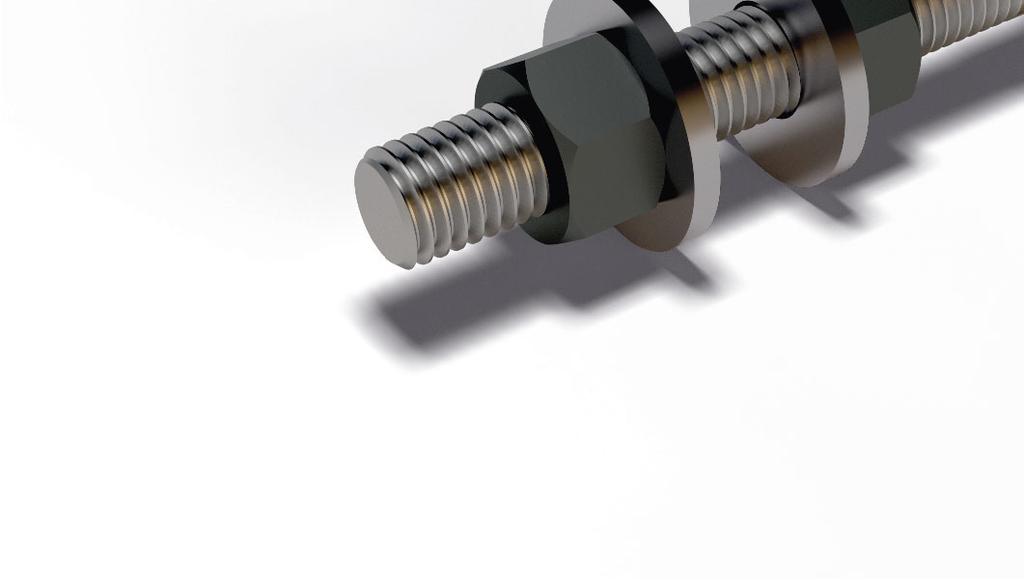
2 HPM Anchor Bolt For bolted connections System benefits Standardized and approved rebar anchor bolt system Approved design parameters Quick deliveries directly from stock Certifi ed production Wide range of products for all anchoring purposes Accessories for quick and easy installation Easy to design with free Peikko Designer software HPM Rebar Anchor Bolts are used to anchor concrete or steel structures and machinery into concrete base structures. The anchors are embedded into concrete and the structures are fastened to bolts by nuts and washers. The joint between two structures is then grouted. The system consists of a wide range of headed and straight anchor bolts, installation accessories, and tools for designers. Headed bolts are used typically in shallow structures for end anchoring, whereas straight bolts are used for lap splices. In addition to plain finish bolts, the products are also available as ECO or Hot-Dip galvanized. Installation templates are provided to ensure easy and correct installation of the anchor bolts.
3 Contents About HPM Rebar Anchor Bolt 4 1. Product Properties Structural behavior Temporary conditions Final conditions Application conditions Loading and environmental conditions Interaction with the base structure Positioning of the anchor bolts Other properties Resistances Tensile, compressive, and shear resistances Combined axial and shear load Fire resistance Selecting HPM Rebar Anchor Bolt 16 Annex A - Supplementary reinforcement to resist tension load 18 A1: Concrete cone reinforcement...18 A2: Splitting reinforcement...19 Annex B - Supplementary reinforcement to resist shear load 20 B1: Edge reinforcement...20 Annex C - Supplementary reinforcement to resist compression load 21 C1: Concrete cone reinforcement for punching...21 C2: Partially loaded areas, Splitting reinforcement...22 Annex D - Transverse reinforcement in the lap zone Annex E - Alternative use of HPM P Anchor Bolts Annex F - Alternative means to transfer shear load Installation of HPM Rebar Anchor Bolts Revision: 001*

4 About HPM Rebar Anchor Bolt 1. Product Properties HPM Anchor Bolts are cast-in-place anchors used to connect structural and non-structural elements to concrete in all types of buildings, warehouses, halls, bridges, dams, and power plants. HPM Anchor Bolts are available in several standard models that are suitable for different application solutions, loading conditions, and cross-sections. Anchor bolts are cast into concrete and transfer loads from the attachment to the base structure. The product range consists of Headed anchor bolts, type HPM L Straight anchor bolts, type HPM P Installation templates HPM L Anchor Bolt HPM P Anchor Bolt Type L bolt anchorage is achieved with a headed stud. Loads are transferred through the bearing of the head against hardened concrete. Due to their relatively short anchorage length, HPM L Anchor bolts are particularly suitable for use in shallow structures (e.g. foundations, slabs, beams). Type P bolt anchorage is achieved by splicing, whereby the bolt overlaps the main reinforcement. Loads are transferred through the bond of the ribbed bars. The primary use of HPM P Anchor Bolts is in structures with sufficient depth (e.g. base columns, columns). Alternative usages are shown in Annex E. HPM Anchor Bolts are pre-designed to be compatible with HPKM Column Shoes, SUMO Wall Shoes, and Beam Shoes, providing a solution for most precast connections (e.g. column to foundation, column to base column, column to column, wall to foundation, wall to wall, beam to column, beam to wall), as well as to secure steel columns or even machine fixings. Anchor bolts are cast into the base structure together with the main and supplementary reinforcement, as detailed in Annexes A, B, C, and D of this manual. The connection is achieved by fastening the anchor bolt to the base plate using nuts and washers. To finalize the connection, the joint is grouted with non-shrinking grouting material. Peikko Bolted Connections can be designed to resist axial forces, bending moments, shear forces, combinations of the above, and fire exposure. The appropriate type and quantity of HPM Anchor Bolts to be used in a connection may be selected and the resistance of the connection verified by using the Peikko Designer software (download from 4 HPM Rebar Anchor Bolt


5 About HPM Rebar Anchor Bolt Figure 1. HPM L Anchor Bolts in a concrete column to footing connection. Figure 2. HPM P Anchor Bolts in a steel column to base column connection. Version: Peikko Group 01/2015 5
6 About HPM Rebar Anchor Bolt 1.1 Structural behavior The loads on fixtures are transmitted to the anchor bolts as statically equivalent, tension, compression, and shear forces. Moment can be resisted by development of a force couple between tensile and compressive forces. The selected size and number of anchor bolts should be sufficient for the load Temporary conditions In the erection stage, the forces acting on anchor bolts are caused principally by self-weight of the attachment as well as by the bending moment and shear force due to wind load. Since the joint is not grouted, all of the forces are carried solely by anchor bolts. In addition, bolts must be verified for buckling and bending. The open joint between the attachment and the base structure must be grouted with a non-shrink grouting material and the grout must harden before loads from other structures can be applied Final conditions In the final stage, after the grout has reached the designed strength, the connection acts as a reinforced-concrete structure. The grout serves as the connection between the attachment and the base structure, transferring compression and shear loads. The grout must have a design compressive strength at least equal to the strength of the highest grade of concrete used in the connected elements. Figure 3. Structural behavior of the bolted connection under temporary and fi nal conditions. Temporary Stage Final Stage N Ed,0 N Ed M Ed,0 M Ed V Ed,0 V Ed z Compression in concrete and grout F cc F st,0 z F sc,0 F st z F sc 6 HPM Rebar Anchor Bolt
7 About HPM Rebar Anchor Bolt 1.2 Application conditions The standard models of HPM Anchor Bolts are pre-designed for use under the conditions mentioned in this section. If these conditions are not met, please contact Peikko Technical Support for custom-designed HPM Anchor Bolts Loading and environmental conditions HPM Anchor Bolts are designed to carry static loads. To ensure resistance to corrosion the concrete cover of HPM Anchor Bolts including washers and nuts must observe the minimum values determined according to the environmental exposure class and intended operating life. As an alternative to concrete cover, Peikko offers two standard surface coating options: ECO Galvanizing and Hot-Dip Galvanizing. Other anti-corrosion methods such as painting on site can also be utilized. For further information please contact Peikko Technical Support. ECO Galvanizing is an economical and ecological way to protect bolts against corrosion, which allows anchor bolts to be galvanized partly or completely. The galvanizing method is a thermally sprayed zinc coating (according to EN ISO 2063). The minimum coating thickness is 100 μm, which fulfills environmental class C3 of standard EN Hot-Dip Galvanized bolts (according to EN ISO 1461) are dipped completely into galvanized material. The minimum coating thickness is 55 μm, which fulfills environmental class C3 of standard EN Examples for ordering galvanized bolts: ECO Galvanized => Name: HPM24P-ECO Hot-Dip Galvanized => Name: HPM30L-HDG Figure 4. ECO Galvanized Bolt. Table 1. Protection of anchor bolts against corrosion in diff erent environmental conditions. Structural Class: S4, Allowance for deviation: Δc dev =10 mm. nominal concrete cover of anchor bolts according to EN Exposure Class c nom [mm] X0 20 XC1 25 XC2 / XC3 35 XC4 40 XD1 / XS1 45 XD2 / XS2 50 XD3 / XS3 55 Version: Peikko Group 01/2015 7
8 About HPM Rebar Anchor Bolt Interaction with base structure HPM Anchor Bolts are pre-designed for use in reinforced base structures (e.g. foundations, slabs, base columns, columns, walls). The standard properties of HPM Anchor Bolts are valid for reinforced normal weight concrete with a strength class in the range C20/25 to C50/60. The anchor bolt may be anchored in cracked and non-cracked concrete. In general, it is conservative to assume that the concrete will be cracked over its service life Positioning of the anchor bolt HPM Anchor Bolts are embedded in concrete up to the marking of the anchorage depth. Where possible, anchor bolts should be arranged symmetrically. The layout must also be coordinated with existing reinforcement to ensure that the bolts can be installed in the intended location. Figure 5. Examples with layout patterns of HPM Anchor Bolts. When placing HPM L Anchor Bolts, the spacing (s min ), edge distance (c min ), and base structure thickness (h min ) must not fall below the minimum values shown in Table 2. It should be noted that the minimum thicknesses (h min ) in Table 2 are for base structures cast directly against soil, h min = h ef + k + c nom, hence c nom = 85 mm. Table 2. Positioning of HPM L bolts in base structure. Anchor Bolt c min [mm] s min [mm] h min [mm] h ef [mm] k [mm] HPM 16 L HPM 20 L HPM 24 L HPM 30 L HPM 39 L Figure 6. Installed HPM L Anchor Bolt. h min h ef k c nom c min s min c min When placing HPM P Anchor Bolts, the minimum edge distance should comply with the concrete cover thickness according to EN , section 4. The bolts must be spaced to prevent bundles from forming and should fulfill the requirements for lapped bars, in EN , sections 8.2 and HPM Rebar Anchor Bolt
9 About HPM Rebar Anchor Bolt 1.3 Other properties HPM Anchor Bolts are fabricated of ribbed reinforcement steel bars with the following material properties: Ribbed Bars B500B EN Standard delivery for each anchor bolt includes two hexagonal nuts and two washers: Washers S355J2 + N EN Nuts Property class 8 EN ISO 4032 / EN Peikko Group s production units are externally controlled and periodically audited on the basis of production certifications and product approvals by various organizations, including Inspecta Certification, VTT Expert Services, Nordcert, SLV, TSUS, and SPSC, among others. Ribbed Bars Threads Anchor head Manufacturing method Mechanical cutting Rolling Forging Length Thread length Manufacturing tolerances ± 10 mm + 5mm, - 0 mm Version: Peikko Group 01/2015 9
10 About HPM Rebar Anchor Bolt Table 3. Dimensions [mm], weight [kg], and color codes of HPM L Anchor Bolts. L M A Ø h ef HPM 16 L HPM 20 L HPM 24 L HPM 30 L HPM 39 L M M16 M20 M24 M30 M39 A Stress area of the thread Ø L Washer Ø 40-6 Ø 44-6 Ø 56-6 Ø 65-8 Ø h ef d h k Weight 0,7 1,2 2,2 4,1 9,2 Color code Yellow Blue Gray Green Orange k d h Table 4. Dimensions [mm], weight [kg], and color codes of HPM P Anchor Bolts. L M A Ø HPM 16 P HPM 20 P HPM 24 P HPM 30 P HPM 39 P M M16 M20 M24 M30 M39 A Stress area of the thread Ø L Washer Ø 40-6 Ø 44-6 Ø 56-6 Ø 65-8 Ø Weight 1,5 2,8 4,9 9,8 21,8 Color code Yellow Blue Gray Green Orange 10 HPM Rebar Anchor Bolt
11 About HPM Rebar Anchor Bolt 2. Resistances 2.1 Tensile, compressive, and shear resistances The resistances of HPM Anchor Bolts are determined by a design concept that makes reference to the following standards: Specification CEN/TS :2009 Specification CEN/TS :2009 EN :2004/AC:2010 EN :2005/AC:2009 EN :2005/AC:2005 ETA-02/0006: ETA-approval ETA-13/0603: ETA-approval Figure 7. Loads and parameters characterizing the joint. V Ed t R h nut N Ed d b = diameter of stress area in thread h nut = thickness of nut t R = equivilent span of anchor bolt = t Grout - h nut + d b / 2 d b d b / 2 t Grout t Fix Height of the joint The resistance of HPM Anchor Bolt connections is defined by bolt steel or anchorage to concrete strength. The required verifications are summarized later in this section. If the anchor bolt s tensile or shear steel resistance cannot be fully developed due to concrete failure then the supplementary reinforcement may be used to carry the forces from the anchor bolt. It is recommended that the resistance be calculated and the required reinforcement for the bolted connections be assigned using the Peikko Designer software. Table 5. Design values for tensile or compressive resistance of individual HPM Anchor Bolt. (Steel strength). HPM 16 HPM 20 HPM 24 HPM 30 HPM 39 N Rd N Rd.0 [kn] Table 6. Design values for shear resistance of individual HPM Anchor Bolt. (Steel strength). The resistances are determined in accordance with ETA-13/0603. Anchor Bolt V Rd [kn] Final Stage V Rd.0 [kn] Erection Stage t Grout [mm] HPM HPM HPM HPM HPM NOTE 1: Resistances V Rd and V Rd,0 in Table 6 are valid for height of joint equal to t Grout. NOTE 2: Resistances shown in Tables 5 and 6 are without simultaneous action of axial and shear load. For combined resistance, see section 2.2 of this manual. Version: Peikko Group 01/
12 About HPM Rebar Anchor Bolt Table 7. verifi cation for HPM Anchor Bolts loaded in tension. The use of Peikko Designer software is recommended to prove the resistance of the following verifications Failure Mode Example HPM L Anchor Bolts HPM P Anchor Bolts Steel strength (for most loaded bolt) (for most loaded bolt) Pull-out strength (for most loaded bolt) Not applicable Concrete cone strength 1) (for anchor group) Not applicable Splitting strength 2) (for anchor group) Not applicable Blow-out strength 3) (for anchor group) Not applicable l 0 Splicing length 4) Not applicable (for most loaded bolt) 1) Not required if supplementary reinforcement is provided according to Annex A1. 2) Not required if the edge distance in all directions c 1,5h ef for one bolt and c 1,8h ef for fastenings with more than one anchor bolt or if supplementary reinforcement is provided according to Annex A2. 3) Not required if the edge distance in all directions c 0,5h ef. 4) See Annex D for required transverse reinforcement in the lap zone. 12 HPM Rebar Anchor Bolt
13 About HPM Rebar Anchor Bolt Table 8. verifi cation for HPM Anchor Bolts loaded in compression. The use of Peikko Designer software is recommended to prove the resistance of the following verifications Failure Mode Example HPM L Anchor Bolts HPM P Anchor Bolts Steel strength (for most loaded bolt) (for most loaded bolt) Buckling strength 1) (for most loaded bolt) (for most loaded bolt) Punching strength under the anchor head 2) (for anchor group) Not applicable l 0 Splicing length 3) Not applicable (for most loaded bolt) Partially loaded areas 4) Local crushing Transverse tension forces only in the final stage (for the base structure) only in the final stage (for the base structure) 1) Not required (according to ETA-13/0603) if the height of the joint does not exceed the grouting thicknesses stated in the installation instructions of this manual. See Table 6 for t Grout. 2) Not required if the thickness of the base structure ensures a sufficient concrete layer under the anchor head or if supplementary reinforcement is provided. Details can be found from Annex C1. 3) See Annex D for the required transverse reinforcement in the lap zone. 4) See Annex C2 for design guidelines and the required splitting reinforcement. Version: Peikko Group 01/
14 About HPM Rebar Anchor Bolt Table 9. verifi cation for HPM Anchor Bolts loaded in shear. The use of Peikko Designer software is recommended to prove the resistance of the following verifications Failure Mode Example HPM L Anchor Bolts HPM P Anchor Bolts Steel strength (for most loaded bolt) (for most loaded bolt) Steel strength with lever arm 1) (for most loaded bolt) (for most loaded bolt) Concrete edge strength 2) Shear perpendicular to the edge Shear parallel to the edge Inclined shear (for anchor group) (for anchor group) Concrete pry-out strength (for anchor group) Not applicable 1) Not required (according to ETA-13/0603) in the final stage if the height of the joint does not exceed the grouting thicknesses stated in the installation instructions of this manual. See Table 6 for t Grout. It should be noted that the check always applies in the erection stage. 2) Not required if the edge distances in all directions c min(10h ef ;60Ø) or if supplementary reinforcement is provided according to Annex B1. 14 HPM Rebar Anchor Bolt
15 About HPM Rebar Anchor Bolt 2.2 Combined axial and shear load When axial and shear forces strain the bolt simultaneously the interaction should be checked by satisfying the following equations for different failure modes and design stages. WITH RESPECT TO STEEL VERIFICATIONS Bolts in Erection Stage The simultaneous axial force and shear force in each bolt shall satisfy the condition:,, +, 1, Bolts in Final Stage The simultaneous tensile force and shear force in each bolt shall satisfy the condition: +, 1 1 ETA-13/0603, Eq. (1) ETA-13/0603, Eq. (10) ETA-13/0603, Eq. (11) where V Rd,0 = shear resistance of bolt, Erection Stage V Rd = shear resistance of bolt, Final Stage N Rd,0 = axial resistance of bolt, Erection Stage N Rd = axial resistance of bolt, Final Stage V1 Ed,0 = shear load on a single bolt, Erection Stage V1 Ed = shear load on a single bolt, Final Stage N1 Ed,0 = axial load on a single bolt, Erection Stage N1 Ed = axial load on a single bolt, Final Stage WITH RESPECT TO CONCRETE VERIFICATIONS (applies only for HPM L Anchor Bolts) Bolts without supplementary reinforcement The simultaneous tensile force and shear force shall satisfy the condition: β N 1,5 + β V 1,5 1 CEN/TS , Eq. (48) Bolts with supplementary reinforcement The simultaneous tensile force and shear force shall satisfy the condition: β N β V CEN/TS , Eq. (49) If the supplementary reinforcement is designed to carry tension and shear forces, Eq. (48) applies. where β N = largest degree of utilization from concrete verifications under tensile force β V = largest degree of utilization from concrete verifications under shear force NOTE: Failure modes β N and β V are those not covered by supplementary reinforcement 2.3 Fire resistance The fire resistance of bolted connection should be verified in accordance with EN The fire design of column connections is implemented into Peikko Designer to enable quick and easy proof of load-bearing function for concrete column connections with HPM Anchor Bolts when exposed to fire. If the fire resistance of the connection is insufficient, the concrete cover must be increased or alternative means used to reach the intended fire resistance class. Please contact Peikko Technical Support for custom designs. Version: Peikko Group 01/

16 Selecting HPM Rebar Anchor Bolt The following aspects must be considered when selecting an appropriate type of HPM Anchor Bolt to be used in bolted connections: Resistances Properties of the grouting Properties of the base structure Position and arrangement of the anchor bolts in the base structure Design value of actions The resistance of Peikko Bolted Connections should be verified for the following design situations: Erection stage Final stage Fire situation Environmental exposure conditions Peikko Designer Column Connection software Peikko Designer is software to be used for designing column connections with Peikko s products. It can be downloaded free of charge from The Column Connection module enables the user to design connections to resist actual loadings and optimize the connections to meet the requirements of the entire project. The software s output reports can also be used to verify the design and output drawings as details of the connection. The summary of the products in the project helps to plan material flow during construction. Figure 8. User interface of Peikko Designer Column Connection. 16 HPM Rebar Anchor Bolt
17 Selecting HPM Rebar Anchor Bolt Typically, the following steps are used for the selection procedure: USER INPUT Materials for column, structure under column, and grouting Geometries of the column and structure under column Design values of the actions erection, final, and fire stages NOTE: Second order effects should be included in the load case Type of column shoes and anchor bolts Column shoe arrangement Column reinforcement (optional) PEIKKO DESIGNER OUTPUT N-M interaction diagram (axial force-bending moment diagram) of joint in final and fire stage N-M interaction diagram of reinforced column Calculation results for column connection in final stage Calculation results for column connection in erection stage Supplementary reinforcement details Summary of products in the project Version: Peikko Group 01/
18 Annex A - Supplementary reinforcement to resist tension load A1: Concrete cone reinforcement If the concrete cone resistance is exceeded, supplementary reinforcement for the tension load should be provided. Detailing of hanger reinforcement for HPM L Anchor Bolts is shown in the following figure. The required quantities of stirrups and surface bars are given in Table 10. Alternative reinforcement arrangements can be calculated using the Peikko Designer Column Connection software in accordance with CEN/TS Table 10. Concrete cone reinforcement (B500B). Stirrups Surface bars c nom R 1,max h ef b Anchor Bolt (per bolt) width of [mm] [mm] [mm] stirrup [mm] HPM 16 L 4 Ø 8 Ø HPM 20 L 4 Ø 8 Ø HPM 24 L 4 Ø 8 Ø HPM 30 L 4 Ø 10 Ø HPM 39 L 4 Ø 12 Ø The reinforcement from Table 10 can be directly applied under the following conditions: The concrete strength class of the base structure is equal to or greater than C25/30 (good bond) The nominal concrete cover is equal to or smaller than 35 [mm] The minimum clear distance (a) between adjacent legs of stirrups should not be less than 21 [mm], requirement according to EN , section 8.2 (maximum size of aggregate = 16 mm ) Figure 9. Illustration of detailing of the supplementary reinforcement in the form of stirrups and hairpins. c nom 2 N Ed c nom Alternative h ef h ef l bd 1 Top-view Detail A a R 1, max 2 Detail A b 1 18 HPM Rebar Anchor Bolt
19 Annex A - Supplementary reinforcement to resist tension load A2: Splitting reinforcement If the splitting resistance is exceeded, supplementary side and top face reinforcement near the concrete surface should be provided to resist the splitting forces and to limit splitting cracks. Detailing of reinforcement for HPM L Anchor Bolts is shown in the following figure. The required quantities of reinforcement bars are given in Table 11. Alternative reinforcement arrangements can be calculated using the Peikko Designer Column Connection software in accordance with CEN/TS The required cross-section A s of the splitting reinforcement may be determined as follows: =0,5 [ ] /, CEN/TS , Eq. (17) where = sum of the design tensile forces of the bolts in tension under the design value of the actions = nominal yield strength of the reinforcing steel 500 N/mm2 γ Ms,re = partial safety factor for steel failure of supplementary reinforcement =1,15 N Ed ƒ yk Table 11. Minimum recommended splitting reinforcement (B500B) per fully loaded anchor bolt. Anchor Bolt A s + [mm2] Selected reinforcement HPM 16 L 71 3 Ø 6 HPM 20 L Ø 6 HPM 24 L Ø 8 HPM 30 L Ø 10 HPM 39 L Ø 12 Critical Edge N Ed Splitting Crack Placement of reinforcement: Splitting reinforcement must be evenly placed along the critical edge(s)* on the side and top faces of concrete member. * The distance from the edge of the concrete surface to the center of the nearest bolt in tension smaller than 1,8h ef. Figure 10. Detail for splitting reinforcement. Example case with one critical edge. N Ed < 1,8h ef 1,5h ef Reinforcement zone c mon Bars against splitting must be located inside effective reinforcement zone (i.e. within a distance 1,5 h ef from bolts in tension). 1 l bd h ef l bd Pos. is the side-face reinforcement of the critical edge or edges of the same direction. 2 Pos. is the top-face reinforcement of the critical edge or edges of the same direction. NOTE: Perpendicular edges should be considered independently (i.e. A s per direction) l bd Constructive Reinforcement Version: Peikko Group 01/
20 Annex B - Supplementary reinforcement to resist shear load B1: Edge reinforcement If the edge cone resistance is exceeded, supplementary reinforcement should be provided based on the corresponding magnitude of the shear force for this edge. The shear force magnitude for the edge under consideration depends on the orientation of the applied load. The requirement and amount of supplementary shear reinforcement for each edge of the concrete member should be checked independently. Detailing of edge reinforcement for HPM L and P Anchor Bolts is shown in the following figure. The required quantities of U-stirrups are given in Table 12. Alternative reinforcement arrangements can be calculated using the Peikko Designer Column Connection software in accordance with CEN/TS Table 12. Concrete edge reinforcement (B500B) per fully loaded anchor bolt in shear. U-Stirrups c 1 c nom e s Anchor Bolt (per bolt) [mm] [mm] [mm] HPM 16 1 Ø HPM 20 1 Ø HPM 24 1 Ø HPM 30 2 Ø HPM 39 3 Ø The reinforcement from Table 12 can be directly applied under the following conditions: The distance between reinforcement and shear force equal to or smaller than e s The edge distance is equal to or greater than c 1 It should be noted that the supplementary reinforcement shown in Table 12 is selected for the edge perpendicular to the applied load, which is the least favorable case. Figure 11. Illustration of detailing of the supplementary reinforcement in the form of loops. V Ed 1 1,5c 1 t Gr t Fix 1 V Ed e s c mon c 1 l bd c 1 NOTE: In Figure 11 it is assumed that the edge of the concrete member parallel to the applied load have sufficient resistance without supplementary reinforcement. 20 HPM Rebar Anchor Bolt
21 Annex C - Supplementary reinforcement to resist compression load C1: Concrete cone reinforcement for punching If the punching resistance under the head of the anchor bolt is exceeded, supplementary reinforcement should be provided. Detailing of supplementary reinforcement for HPM L Anchor Bolts is shown in following figure. The required quantities of stirrups are given in Table 13. Reinforcement may be omitted if the concrete thickness h under the bolt s head is equal to or greater than h req (see Figure 12). Table 13. Concrete cone reinforcement (B500B). h req A s Stirrups Anchor Bolt (per bolt) [mm] [mm2] HPM 16 L Ø 6 HPM 20 L Ø 8 HPM 24 L Ø 8 HPM 30 L Ø 10 HPM 39 L Ø 14 NOTE: Pre-calculated h req thicknesses are relevant only for cases where the punching cone under the bolt s head is not limited by adjacent cones or the edges of the base structure (see Figure 12). The inclination angle of stress cone is 45. The reinforcement from Table 13 can be directly applied under the following conditions: The concrete strength class of base structure is equal to or greater than C25/30 (good bond) Stirrups are located inside the stress cone and anchored according to reinforced concrete standards It should be noted that punching reinforcement, if in form of closed stirrups, may be used as hanger reinforcement for tension. Figure 12. Reinforcing the conical fracture under the bolt. N Ed Alternative with U-Stirrups 1 l bd h Version: Peikko Group 01/
22 Annex C - Supplementary reinforcement to resist compression load C2: Partially loaded areas, Splitting reinforcement If the compression resistance of the base structure is exceeded, local crushing should be considered. For that reason, the concrete strength class of the lower column in the column-to-column connections should be at least the same as that used in the upper column. Local crushing can be prevented by expanding the base structure by dimension Δ (see Figure 13). In addition, splitting reinforcement should be provided to resist transverse tension forces in the base structure. The stirrups should be distributed uniformly in the direction of the tension force over the height h, where compression trajectories are curved. In the absence of better information, height h can be taken as 2Δ. Figure 13. Column connection with two diff erent size sections. Splitting reinforcement in base column. a) Whole cross section compressed : b) Cross section, balance failure : B Δ H Δ 1 A sh 1 Column N Ed Bolt 1 A sh Tension Side Δ X Δ H A sh PEDESTAL h Δ B Δ B + 2Δ Δ B Δ Table 14. The expansion Δ of base structure and required splitting stirrups (B500B). Concrete Grade (Column) Concrete Grade (Base Column) a) Whole cross section compressed Δ [mm] b) The bolts of the tension side yield (balance failure) Δ [mm] reinforcement area Stirrups with 2-cuts A sh [mm2] C30/37 C25/30 Δ=0,10 H Δ=0,06 H A sh =B H/933 C35/45 C25/30 Δ=0,20 H Δ=0,12 H A sh =B H/474 C40/50 C25/30 Δ=0,30 H Δ=0,18 H A sh =B H/320 C50/60 C35/45 Δ=0,21 H Δ=0,13 H A sh =B H/317 C60/75 C35/45 Δ=0,36 H Δ=0,22 H A sh =B H/ HPM Rebar Anchor Bolt
23 Annex C - Supplementary reinforcement to resist compression load DESIGN EXAMPLE A concrete 400 [mm] x 400 [mm] column (C30/37) bears on a base column (C20/25). Determine the minimum cross section and required splitting reinforcement of the base structure to resist the maximum compression force applied from the supported column. Loading Situation: Column under uniaxial compression without bending moment. Δ H+2 Δ H Δ Δ B B+2 Δ Δ A c0 Column: ƒ cd,c = 20,00 N/mm2 A c1 Base: ƒ cd,b = 13,33 N/mm2 The concentrated resistance force of partially loaded area: where A c0 A c1 ƒ cd,b =, 3,0, is the loaded area is the maximum design distribution area with a similar shape to A c0 is the design compressive strength of base structure EN , Eq. (6.63) Substituting in Eq. (6.63): A c0 = B H = = mm2 A c1 = (B+2 Δ) (H+2 Δ) = (400+2 Δ) (400+2 Δ)=(400+2 Δ)2 F Rdu = maximum applied force (i.e. ultimate strength of an axially loaded column) = A c0 ƒ cd,c = B H ƒ cd,c = = N = 3200 kn where ƒ cd,c is the design compressive strength of column Solving this quadratic equation: ( +2 ) ( +2 ), =, = 100 Minimum cross-section of base column: (B + 2 Δ) x (H + 2 Δ) = 600 [mm] x 600 [mm] Splitting force (according to EN , section 6.5): 400 =0,25 1 =0, =266, splitting reinforcement area (2-cuts, B500B): = = =306,7 1,15 where ƒ yk = characteristic yield strength of reinforcement = partial safety factor for reinforcement γ s Selected stirrups: 7Ø8 or 4Ø10 Version: Peikko Group 01/
24 Annex D - Transverse reinforcement in the lap zone Long HPM P Anchor Bolts are designed for use in lap splices with the main reinforcement of the base structure. The base structure must be reinforced with at least the same cross section area of longitudinal bars corresponding to the bolts. Adequate transverse reinforcement A st should be provided in the lap zone (see Figure 14). The required quantities of stirrups are given in Table 15. Alternative reinforcement arrangements can be calculated using the Peikko Designer Column Connection software. Table 15. Reinforcement for lap splices, (B500B). Total amount of l 0 Anchor Bolt stirrups [mm] HPM 16 P 4+4 Ø HPM 20 P 3+3 Ø HPM 24 P 4+4 Ø HPM 30 P 4+4 Ø HPM 39 P 6+6 Ø The reinforcement from Table 15 can be directly applied under the following conditions: The concrete strength class of base structure is equal to or greater than C25/30 (good bond) The bolts are loaded in tension Figure 14. Transverse reinforcement for lapped splices. Detail of reinforcement when bars in tension. N Ed A Key: w l 0 A L is spacing of stirrups 150 mm is lap splice length is thread length is bolt length l 0 l 0 /3 A st /2 L w w l 0 /3 A st /2 w 1 w w w Main bars (according to design engineer) 24 HPM Rebar Anchor Bolt
25 Annex E Alternative use of HPM P Anchor Bolt 1. HPM P Bolts as alternative to lap splices can be anchored as longitudinal reinforcement by providing sufficient tension/compression development length. It should be noted that this solution might require additional verifications and reinforcement for the base structure. The design anchorage length l bd to anchor the force N Ed acting on a bolt must be checked in accordance with EN , section 8.4. l Anchorage Length l bd Base Structure 2. HPM P Anchor Bolts can be also installed in shallow structures with limited thickness by bending them. The minimum mandrel diameter Ø m,min must be checked for each individual case (according to EN , section 8.3) to avoid bending cracks in the anchor bolt and to avoid failure of the concrete inside the bend. Øm Ø m,min Bent HPM P Øm Bent anchor bolts can be manufactured and delivered according to specification. l bd Beam 3. If requested, extra-long HPM P Anchor Bolts are available for structural solutions such as column-to-column connections through the beam. Where l 0 is the design lap length in accordance with EN , section l 0 Lap Length Column Joint Ordering non-standard HPM P Anchor Bolt: All dimensions in [mm] 1. Straight HPM P Anchor Bolt => HPM(*)P l Example 1: HPM30P Bent HPM P Anchor Bolt => HPM(*)P l Bent(α)- B Example 2 => HPM30P 2000 Bent Example 3 => HPM30P 2500 Bent where * is the size of the bolt l is the total length of the bolt α is the angle of bend [degrees] B is the position of bend l B α Version: Peikko Group 01/
26 Annex F Alternative means to transfer shear load There are two principal ways of transferring shear force from columns into the base structure: By anchor bolt shear resistance (see Table 6) By friction resistance between the base plate and grout: F f,rd = μ N Ed where μ N Ed is the friction coefficient between the base plate and grout = 0,20 (without additional tests) is the design value of the total axial force NOTE: If the column is loaded with tensile axial force, μ N Ed = 0 Alternative ways used in resisting large shear forces: Shear dowel (see Figure 15a) Embedding the column in the base structure (see Figure 15b) Transferring force to the floor slab using hairpin bars (see Figure 15c) Figure 15. Details of alternative means of transfering shear load. V Ed Non-shrinking grout Non-shrinking grout V Ed a) Shear Dowel b) Column Embedment V Ed Hairpin Reinforcing Bar Concrete floor slab Base structure c) Hairpin detail 26 HPM Rebar Anchor Bolt


27 Installation of HPM Rebar Anchor Bolts Identification of the product HPM Anchor Bolts are available in standard models (16, 20, 24, 30, and 39) analogous to the M-thread diameter of the bolt. The model of anchor bolt can be identified by the name in the label on the product and the color of the product. Forming a bolt group Bolts are collected into bolt groups using the PPL Installation Template. The installation template enables bolt groups to be centralized on the horizontal plane in exactly the right place and easily adjusted to the correct casting level. HPM Anchor Bolt color identifi cation. Anchor Bolt Thread diameter [mm] Color code Installation Template HPM Yellow PPL 16 HPM Blue PPL 20 HPM Gray PPL 24 HPM Green PPL 30 HPM Orange PPL 39 The PPL Installation Template is a steel plate. Anchor Bolts are fixed through the holes on the template with nuts and washers. The PPL installation plate has alignment marks for accurate positioning of the anchor bolt group. Anchor bolts also have center marks on the top of each bolt for alternative positioning methods. To prevent displacement during the concreting process, the template should be fixed securely to the supporting base by its fixing recesses at the sides. Concrete can be poured easily through the hole in the middle of the template. After casting, the installation template is detached and can be reused.
28 Installation of HPM Rebar Anchor Bolts Ordering PPL Installation Templates When PPL Installation Templates are ordered the thread diameter of bolts, the number of bolts and the center-tocenter dimensions must be specified. Examples of installation plates: 1. PPL x360: 4 pieces M39 bolts in square form. 2. PPL x400: 4 pieces M39 bolts in rectangular form. 3. PPL x( ): 6 pieces M30 bolts rectangular form. 4. PPL30-8 ( )x( ): 8 pieces M30 bolts in the form of a square. 5. PPL x300: 3 pieces M30 bolts in the form of rectangular triangles. 6. PPL24-8 D400: 8 pieces M24 bolts in the form of circles with diameter of 400 mm Ø400 PPL Installation Templates can also be manufactured according to drawings that present the location of the bolts and thread diameters.
29 Installation of HPM Rebar Anchor Bolts Bolt installation and installation tolerances The bolts are installed to the height level according to dimension h b given in table below. The height level is measured from the surface of concrete, and the level tolerance is ±20 mm. Each anchor bolt includes a marking of the anchorage depth. Installation tolerances and the anchor bolt`s protrusion from the concrete. Top level of base structure h b Installation tolerance Grout t Grout Installation tolerance Anchor Bolt HPM 16 HPM 20 HPM 24 HPM 30 HPM 39 Thickness of grouting t Grout [mm] Protrusion of the bolt h b [mm] Installation tolerance for the bolt [mm] ±3 ±3 ±3 ±3 ±3 Bending the bolts HPM Anchor Bolts are made of B500B ribbed reinforcement steel. Bending must be done in accordance with EN See Annex E of this manual with application examples. Welding the bolts Welding of the bolts should be avoided, although all materials used in HPM Anchor Bolts are weldable (except the nuts). Requirements and instructions of standard EN : Welding of reinforcing steel, Part 1: load bearing welding joints shall be taken into account when welding rebars.


30 Installation of HPM Rebar Anchor Bolts Existing buildings Where placing anchor bolts adjacent to walls or other obstructions, construction sequences should be considered. It is necessary to check that the erector will have enough access to tighten the nuts. If special setting is required, please contact Peikko Technical Support. 60 Existing Structure Erection of the attachment Before erecting the attachment, the upper nuts and washers are removed from the anchor bolts. The lower leveling nuts and washers are adjusted to the correct level. The attachment is erected directly on the pre-leveled washers and nuts. An alternative method is to place shims between anchor bolts and adjust them to the proper level. The lower leveling ling nuts must be leveled at least 5 mm under the top level el of shims to ensure that the attachment will rest first on the shims.

 or open-ended slogging wrench (DIN 133) and a 1,5")


31 Installation of HPM Rebar Anchor Bolts Securing the connection The upper nuts and washers are screwed onto the bolts and the attachment is aligned in the vertical position using leveling nuts. It is practical to use two theodolites from different directions to ensure verticality. The nuts are tightened at least to the minimum torque given in the table below. Adequate torque can be achieved typically by impacts of a slogging ring wrench (DIN 7444) or open-ended slogging wrench (DIN 133) and a 1,5 kg sledgehammer. Recommended minimum T min and maximum T max torque values of nuts. Anchor Bolt T min [Nm] T max [Nm] Size of the slogging wrench HPM mm HPM mm HPM mm HPM mm HPM mm Grouting the joint Before loading the attachment with any other structures the joint must be grouted following the grout supplier s instructions. The grouting must be non-shrinking and have a strength according to the plans. To avoid air being trapped in the joint, it is recommended that grout be poured from one side only. Grouting formwork is made so that adequate concrete cover for anchor bolts is achieved.
32 Installation of HPM Rebar Anchor Bolts Instructions for controlling bolt installation Before casting: Ensure that the right PPL Installation Template is being used (axial distances, thread size) Verify the location of the bolt group Ensure that the reinforcement required by the bolts has been installed Ensure that the bolts are at the correct level Ensure that the installation plate and bolt group are not rotated Ensure that the bolt group is fixed in such a way that no movement can occur during casting After casting: Ensure that the location of the bolt group is within the allowance for tolerance. Greater variations must be reported to the structural designer Protect the thread until the erection of the attachment (tape, plastic tube, etc.) Instructions for controlling attachment installation The joints must be made according to the installation plan drafted by the structural designer. If needed, Peikko s technical support can provide advice. Check the following: The installation order Supports and bracing during installation Instructions for tightening the nuts Instructions for joint casting
33 Notes Version: Peikko Group 01/
34 Notes 34 HPM Rebar Anchor Bolt
35 Technical Manual Revisions Version: PEIKKO GROUP 01/ Revision:### New cover design for 2018 added. Version: Peikko Group 01/
36 Resources DESIGN TOOLS Use our powerful software every day to make your work faster, easier and more reliable. Peikko design tools include design software, 3D components for modeling programs, installation instructions, technical manuals and product approvals of Peikko s products. peikko.com/design-tools TECHNICAL SUPPORT Our technical support teams around the world are available to assist you with all of your questions regarding design, installation etc. peikko.com/technical-support APPROVALS Approvals, certificates and documents related to CE-marking (DoP, DoC) can be found on our websites under each products product page. peikko.com/products EPDS AND MANAGEMENT SYSTEM CERTIFICATES Environmental Product Declarations and management system certificates can be found at the quality section of our websites. peikko.com/qehs
Erstantie 2, FIN Villähde Tel , Fax
 www.anstar.eu 2 www.anstar.eu 3 CONTENTS Page 1 PRODUCT DESCRIPTION...4 2 MATERIALS AND STRUCTURE...4 2.1 PRODUCT RANGE...4 2.2 MATERIALS...4 2.3 MANUFACTURING...4 2.4 MANUFACTURING TOLERANCES...4 2.5
WELDA FASTENING PLATES
 FASTENING PLATES Author: Markus Junes, M. Sc. Civ. Eng. R&D Manager, Peikko Group 1. INTRODUCTION Peikko Group has launched a new family of Fastening Plate products with resistances calculated on the basis
TECHNICAL MANUAL. TERADOWEL and ULTRADOWEL. Reliable Dowel System for Floor Joints
 TECHNICAL MANUAL TERADOWEL and ULTRADOWEL Reliable Dowel System for Floor Joints Version: PEIKKO GROUP 11/2018 TERADOWEL and ULTRADOWEL Reliable Dowel System for Floor Joints Dowels manufactured from high
TECHNICAL MANUAL. OPTIMAJOINT Free Movement Joint. Free Movement Joint System for Heavy Traffic
 TECHNICAL MANUAL OPTIMAJOINT Free Movement Joint Free Movement Joint System for Heavy Traffic Version: PEIKKO GROUP 12/2018 OPTIMAJOINT Free Movement Joint Free Movement Joint System for heavy traffic
ALP-C Anchor Bolts User Manual 2
 2 ALP-C Anchor Bolts Revision 12/2017 3 TABLE OF CONTENTS 1 ALP-C ANCHOR BOLTS... 4 2 BOLT APPLICATIONS... 4 2.1 Heavy-duty concrete element frames of industrial buildings... 4 2.2 Composite column and
Look Our New Technology
 1. PRECAST WALL CONNECTORS Tunel Pey Khazar PSK Wall Nail are precast wall connectors designed for tension splicing. The structural connection between precast wall and other concrete element is achieved
HUS 6 Screw anchor, Redundant fastening
 HUS 6 Screw anchor, Anchor version HUS-A 6 Carbon steel Concrete Screw with hex head HUS-H 6 Carbon steel Concrete Screw with hex head HUS-I 6 Carbon steel Concrete Screw with hex head Benefits - Quick
Thread protection accessories are installed at the MODIX production factory and delivered with couplers.
 Installation of MODIX Rebar Coupler Identification of the product The type of MODIX Rebar Coupler can be identified by the marking on the product. Size of the Coupler can be identified also according to
CONNECTIONS FOR CONTINUOUS FRAMING IN PRECAST CONCRETE STRUCTURES
 CONNECTIONS FOR CONTINUOUS FRAMING IN PRECAST CONCRETE STRUCTURES G.Krummel PEIKKO GmbH, Waldeck, Germany Abstract Connections for continuous framing in precast concrete structures have been a problem
Design of structural connections for precast concrete buildings
 BE2008 Encontro Nacional Betão Estrutural 2008 Guimarães 5, 6, 7 de Novembro de 2008 Design of structural connections for precast concrete buildings Björn Engström 1 ABSTRACT A proper design of structural
Anchor HSA Fastening. Technology Manual HSA. Stud anchor. Version /
 Anchor HSA Fastening Stud anchor Technology Manual HSA Stud anchor Version 2016-09 09 / 2016 1 HSA Stud anchor Anchor version Benefits HSA Carbon steel with DIN 125 washer HSA-F Carbon steel hot dipped
Moment Resisting Connections for Load Bearing Walls
 PRECAST: MOMENT RESISTING CONNECTIONS Moment Resisting Connections for Load Bearing Walls Manish Khandelwal Sr. Structural Engineer, Building Structures, Sweco India Private Limited Design philosophy for
TECHNICAL MANUAL. COLIFT Mounting System. Safe and Time-Saving Lifting of Precast Columns
 TECHNICAL MANUAL COLIFT Mounting System Safe and Time-Saving Lifting of Precast Columns Version: PEIKKO GROUP 12/2017 COLIFT Mounting System for precast concrete elements Fast and secure mounting of precast
SPECIFICATION FOR HIGH STRENGTH STRUCTURAL BOLTS
 UDC 621.882.211 [669.14.018.291] IS : 3757-1985 (Reaffirmed 2003) Edition 3.2 (1989-07) Indian Standard SPECIFICATION FOR HIGH STRENGTH STRUCTURAL BOLTS ( Second Revision ) (Incorporating Amendment Nos.
SECTION CONCRETE REINFORCEMENT FOR STEAM UTILITY DISTRIBUTION
 PAGE 032015-1 SECTION 032015 PART 1 - GENERAL 1.1 RELATED DOCUMENTS A. Drawings and general provisions of the Contract, including General and Supplementary Conditions and Division 01 Specification sections,
SECTION STRUCTURAL STEEL FRAMING PART 1 - GENERAL 1.1 RELATED DOCUMENTS
 SECTION 05 12 00 - STRUCTURAL STEEL FRAMING PART 1 - GENERAL 1.1 RELATED DOCUMENTS A. Drawings and general provisions of the Contract, including General and Supplementary Conditions and Division 01 Specification
ERECTION & CONSTRUCTION
 ERECTION & CONSTRUCTION High Strength Structural Bolting Author: Clark Hyland Affiliation: Steel Construction New Zealand Inc. Date: 24 th August 2007 Ref.: Key Words High Strength Bolts; Property Class
Schöck dowel Type SLD plus
 Schöck dowel Type plus Schöck dowel type plus Contents Page Design joints 10 Connection options 11 Dimensions 12-13 Installation information/notes 14-15 Design/On-site reinforcement 16-29 Punching shear
PEC-TA Cast-in Channels and Bolts. Certified German quality for high-end fixing solutions. Advantages of using PEC Cast-in Channels.
 Fixing Technology s and Bolts PEC Cast-in Channels are ideally suited for quick, reliable and cost-efficient fixing of different construction elements. The possibility of making simple and flexible adjustments
A. Extent of structural precast concrete work is shown on drawings and in schedules.
 SECTION 03 41 00 - STRUCTURAL PRECAST CONCRETE PART 1 GENERAL 1.1 RELATED DOCUMENTS A. Drawings and general provisions of Contract, including General and Supplementary Conditions and Division 1 specification
GLOSSARY OF TERMS SECTION 8
 GLOSSARY OF TERMS SECTION 8 Anchor Bolt Angle Base Plate Bay Blocking CCB Centerline Chord Cladding Clip Closure Strip An A-307 steel bolt embedded in the concrete footing to anchor the base plate of the
Cast-in Ferrule Connections Load/Displacement Characteristics in Shear
 Cast-in Ferrule Connections Load/Displacement Characteristics in Shear Ian Ferrier 1 and Andrew Barraclough 2 1 Product Manager - Connections, ITW Construction Systems ANZ. 2 Research and Development Manager,
1. Enumerate the most commonly used engineering materials and state some important properties and their engineering applications.
 Code No: R05310305 Set No. 1 III B.Tech I Semester Regular Examinations, November 2008 DESIGN OF MACHINE MEMBERS-I ( Common to Mechanical Engineering and Production Engineering) Time: 3 hours Max Marks:
FRANK. Technologies for the construction industry. Egcodorn Shear force dowel for expansion joints
 FRANK Technologies for the construction industry Egcodorn Shear force dowel for expansion joints Contents Max Frank GmbH & Co. KG Mitterweg 1 94339 Leiblfi ng Germany Phone +49 9427 189-0 Fax +49 9427
HSV EXPANSION ANCHOR. Technical Datasheet Update: Dec-17
 HSV EXPANSION ANCHOR Technical Datasheet Update: Dec-17 HSV Expansion anchor Economical expansion anchor for uncracked concrete Anchor version HSV (F) (M8-M16) HSV-BW (M8-M16) Benefits - Torque-controlled
Section 914. JOINT AND WATERPROOFING MATERIALS
 914.01 Section 914. JOINT AND WATERPROOFING MATERIALS 914.01. General Requirements. Joint and waterproofing material for use in concrete construction must meet the requirements of this section. 914.02.
Shear force transmission in expansion joints
 for better solutions Shear dowel Shear force transmission in expansion joints Reliable expansion joint dowelling in concrete structural elements General Single shear dowel HED Expansion joint dowelling
Unicon QwikFoot and QwikFix Threaded Inserts. Design Guide
 Unicon QwikFoot and QwikFix Threaded Inserts Design Guide November 2017 Unicon Precast Concrete Accessories Unicon Systems is a division of Ancon Building Products. When Unicon Systems joined Ancon, it
Bolt Material Types and Grades 1- Bolts made of carbon steel and alloy steel: 4.6, 4.8, 5.6, 5.8, 6.8, 8.8, 10.9 Nuts made of carbon steel and alloy
 Bolt Material Types and Grades 1- Bolts made of carbon steel and alloy steel: 4.6, 4.8, 5.6, 5.8, 6.8, 8.8, 10.9 Nuts made of carbon steel and alloy steel: 4, 5, 6, 8, 10, 12 2- Bolts made of stainless
European Technical Approval ETA-10/0413
 ETA-Danmark A/S Kollegievej 6 DK-2920 Charlottenlund Tel. +45 72 24 59 00 Fax +45 72 24 59 04 Internet www.etadanmark.dk Authorised and notified according to Article 10 of the Council Directive 89/106/EEC
Dowel-type fasteners. Timber Connections. Academic resources. Introduction. Deferent types of dowel-type fasteners. Version 1
 Academic resources Timber Connections Dowel-type fasteners Version 1 This unit covers the following topics: Deferent types of dowel-type fasteners Introduction There are four criteria designers should
SECTION METAL FABRICATIONS
 SECTION 05100 PART 1 - GENERAL 1.01 DESCRIPTION A. Section includes specifications for metal fabrications, including minimum requirements for fabricator, and galvanizing. 1.02 REFERENCE STANDARDS A. ASTM
Table of Contents. What's New in GRAITEC Advance BIM Designers 2018 R2 ADVANCE BIM DESIGNERS CONCRETE SERIES... 4
 What's New 2018 R2 Table of Contents ADVANCE BIM DESIGNERS CONCRETE SERIES... 4 REINFORCED CONCRETE FOOTING DESIGNER... 4 Multi-layer soil calculation... 4 Bottom Constructive Reinforcement... 5 REINFORCED
European Technical Assessment ETA-13/0029 of 11/07/2017
 ETA-Danmark A/S Göteborg Plads 1 DK-2150 Nordhavn Tel. +45 72 24 59 00 Fax +45 72 24 59 04 Internet www.etadanmark.dk Authorised and notified according to Article 29 of the Regulation (EU) No 305/2011
Statement for nail plate LL13 Combi
 STATEMENT NO VTT-S-0369-17 1 (5) Request by Order Contact person Ristek Oy Askonkatu 11 FI-15110 Lahti 15.3.017 Kimmo Köntti VTT Expert Services Ltd Ari Kevarinmäki P.O. Box 1001, FI-0044 VTT Tel. +358
1.1 SUMMARY. A. This Section includes the following: 1. Loose steel lintels. 2. Shelf angles. 3. Metal floor plate. 4. Pipe bollards.
 PART 1 - GENERAL 1.1 SUMMARY A. This Section includes the following: 1. Loose steel lintels. 2. Shelf angles. 3. Metal floor plate. 4. Pipe bollards. B. See Division 5 Section "Pipe and Tube Railings"
Schöck Dorn type LD, LD-Q
 Schöck Dorn type Schöck Dorn type, -Q Schöck Dorn Typ Lastdorn zur Übertragung von Querkräften in Dehnfugen zwischen Betonbauteilen bei gleichzeitiger Verschieblichkeit in Richtung der Dornachse. Schöck
European Technical Assessment ETA 15/0029 of 12/06/2017
 RISE Research Institutes of Sweden AB RISE Certifiering Box 553 SE-371 23 Karlskrona Sweden Member of www.eota.eu Tel: +46 10 516 63 00 Web: www.ri.se Mail: certifiering@ri.se European of 12/06/2017 General
Edgerail Aluminum Bridge Railing System Specification & Installation Instructions
 Edgerail System Specification & Installation Instructions Hill & Smith, Inc 1000 Buckeye Park Road Columbus, Ohio 43207 Tel: 614-340-6294 Fax: 614-340-6296 www.hillandsmith.com Section A System Specification
Optimast Installation Method Statement. F108.
 Optimast Installation Method Statement. F108. Contents Page 1) Product Description. 2) Durability....... 3) Profile & Baseplate..... 4) Anchor Cradle and Foundation Stud Set Detail Drawings 4a) 127...
Eurocode EN Eurocode 3: 3 Design of steel structures. Part 1-1: General rules and rules for buildings
 Eurocode EN 1993-1-1 Eurocode 3: 3 Design of steel structures Part 1-1: General rules and rules for buildings Eurocode EN 1993-1-1 Eurocode 3 applies to the design of buildings and civil engineering works
PIP STF05121 Anchor Fabrication and Installation Into Concrete
 June 2017 Structural PIP STF05121 Anchor Fabrication and Installation Into Concrete PURPOSE AND USE OF PROCESS INDUSTRY PRACTICES In an effort to minimize the cost of process industry facilities, this
Instruction Manual for installing
 Instruction Manual for installing Preloaded (HSFG) Bolting with TurnaSure DIRECT TENSION INDICATORS CE Marked EN 14399-9 TurnaSure LLC TABLE OF CONTENTS Introduction... 1 Theory of Preloaded Bolting Assemblies...
Letter of Transmittal/Submittal
 Letter of Transmittal/Submittal FROM: TO: Baker Concrete Construction 1904 Jasper Street DATE JOB NUMBER 09/23/10 Aurora, CO 80011 9921 303.367.8111 ATTENTION Nick Dewald 937.536.9000 RE: Bruce Herman
Subject of approval: fischer concrete screw ULTRACUT FBS II for the temporary fastening of building site equipment
 Date: Reference: 13 July 2016 I 25-1.21.8-49/15 Approval number: Validity Z-21.8-2049 from: 13 July 2016 Applicant: fischerwerke GmbH & Co. KG Klaus-Fischer-Straße 1 72178 Waldachtal to: 13 July 2021 Subject
2016 AASHTO BRIDGE COMMITTEE AGENDA ITEM: 24 (REVISION 1) SUBJECT: LRFD Bridge Design Specifications: Section 6, Various Articles (2)
 SUBJECT: LRFD Bridge Design Specifications: Section 6, Various Articles (2)") 2016 AASHTO BRIDGE COMMITTEE AGENDA ITEM: 24 (REVISION 1) SUBJECT: LRFD Bridge Design Specifications: Section 6, Various Articles (2) TECHNICAL COMMITTEE: T-14 Steel REVISION ADDITION NEW DOCUMENT DESIGN
2016 AASHTO BRIDGE COMMITTEE AGENDA ITEM: 24 (REVISION 1) SUBJECT: LRFD Bridge Design Specifications: Section 6, Various Articles (2) TECHNICAL COMMITTEE: T-14 Steel REVISION ADDITION NEW DOCUMENT DESIGN
HPD Aerated concrete anchor. Approvals / certificates. Basic loading data (for a single anchor)
") HPD Anchor version HPD Benefits - anchor for autoclaved aerated concrete - maximum use of base material capacity - setting without drilling Autoclaved aerated concrete Fire resistance Sprinkler approved
HPD Anchor version HPD Benefits - anchor for autoclaved aerated concrete - maximum use of base material capacity - setting without drilling Autoclaved aerated concrete Fire resistance Sprinkler approved
Internal threaded version: HSC-I carbon steel internal version HSC-IR Stainless steel version (A4) Hilti anchor design software
 Hilti anchor design software") Anchor version Benefits Internal threaded version: HSC-I carbon steel internal version HSC-IR Stainless steel version (A4) the perfect solution for small edge and space distance suitable for thin concrete
Anchor version Benefits Internal threaded version: HSC-I carbon steel internal version HSC-IR Stainless steel version (A4) the perfect solution for small edge and space distance suitable for thin concrete
Utility Structures. Utility vaults, trenches, transformer pads Electrical Pole Bases and switching cubicles
 Utility Structures Utility vaults, trenches, transformer pads Electrical Pole Bases and switching cubicles PRODUCT GUIDE & TECHNICAL REFERENCE MANUAL Providing the right solutions. UTILITY STRUCTURES Perfect
JVI Vector Connector
 The JVI Vector Connector User Guidelines 1 of 11 INTRODUCTION JVI designed the Vector Connector for use as shear and alignment connections between precast concrete elements such as double-tee flanges,
TECHNICAL DATA SHEET
 Certificates ETA 16/0596 ETA 16/0595 09.10.2016 Page 1 of 6 Certification for anchoring of threaded bars in non-cracked concrete (Option 7) Certification for anchoring in solid and hollow masonry, with
1/2/2016. Lecture Slides. Screws, Fasteners, and the Design of Nonpermanent Joints. Reasons for Non-permanent Fasteners
 Lecture Slides Screws, Fasteners, and the Design of Nonpermanent Joints Reasons for Non-permanent Fasteners Field assembly Disassembly Maintenance Adjustment 1 Introduction There are two distinct uses
SECTION ARCHITECTURAL PRECAST CONCRETE
 PART 1 - GENERAL 1.1 SUMMARY A. This Section includes the following: 1. Column covers. 1.2 SUBMITTALS A. Design Mixtures: For each precast concrete mixture. Include compressive strength and waterabsorption
HARDLOCK NUT RIM & HARDLOCK NUT BASIC
 1 Clamp Load [kn] FEATURES OF HARDLOCK NUT Reusable without reduction in performance! Full torque management and completely fastened even with ZERO (0) clamp load! Available in various materials and surface
CARES Technical Approval Report TA1-B 5042
 CARES Technical Approval Report TA1-B 5042 Issue 4 Dextra ROLLTEC Standard, Positional and Caging Couplers Assessment of the Dextra ROLLTEC Standard, Positional and Caging Coupler Product and Quality System
PUSH-PULL-PROPS. and accessories ROBUSTA-GAUKEL GMBH MOUNTING TECHNOLOGY &CO.KG
 PUSH-PULL-PROPS and accessories MOUNTING TECHNOLOGY ROBUSTA-GAUKEL GMBH &CO.KG MOUNTING TECHNOLOGY PUSH-PULL-PROPS AND ACCESSORIES INDEX General information...................... 3 Push-pull-prop Type
HUS3 redundant SCREW ANCHOR. Technical Datasheet Update: Dec-17
 HUS3 redundant SCREW ANCHOR Technical Datasheet Update: Dec-17 HUS3 Screw anchor Ultimate performance screw anchor for redundant fastening applications Anchor version HUS3-H (R) HUS3-C HUS3-A Benefits
3.1 General Provisions
 WOOD FRAME CONSTRUCTION MANUAL 107 3.1 General Provisions 3.1.1 Prescriptive Requirements The provisions of this Chapter establish a specific set of resistance requirements for buildings meeting the scope
1. In the Y direction: to the vertical axis of the wall (middle of the wall)
") Installation of TENLOC Panel Connectors Precast Factory Installation of the TENLOC The is placed into the reinforcement of the wall and attached to the mold with nails. The wall thickness must be minimum
Installation of TENLOC Panel Connectors Precast Factory Installation of the TENLOC The is placed into the reinforcement of the wall and attached to the mold with nails. The wall thickness must be minimum
TENANT IMPROVEMENT 16 FEBRUARY WEST 27TH STREET, 4TH FLOOR 100% CD OWNER/BID ADD 1-03/08/2018
 SECTION 055000 - PART 1 - GENERAL 1.1 RELATED DOCUMENTS A. Drawings and general provisions of the Contract, including General and Supplementary Conditions and Division 01 Specification Sections, apply
Bolt Tensioning. This document is a summary of...
 If you want to learn more about best practice machinery maintenance, or world class mechanical equipment maintenance and installation practices, follow the link to our Online Store and see the Training
European Technical Assessment. ETA-14/0426 of 21 December English translation prepared by DIBt - Original version in German language
 European Technical Assessment ETA-14/0426 of 21 December 2016 - Original version in German language General Part Technical Assessment Body issuing the European Technical Assessment: Trade name of the construction
Meva Guided Screens MGS Technical Instruction Manual
 Meva Guided Screens MGS Technical Instruction Manual Product Characteristics: The MEVA Guided Screens (MGS) system encloses complete floors especially in high-rise construction independent of the height
SECTION R507 DECKS DECKING LEDGER BOARD BEAM. FOOTING BEAM SPAN CANTILEVER For SI: 1 inch = 25.4 mm FIGURE R507.2 DECK CONSTRUCTION
 SECTION R507 DECKS R507.1 Application. The provisions of this section shall provide prescriptive requirements for the design and construction of all uncovered, wood-framed, single-span exterior decks.
PART MATERIALS. Section Fencing Materials. Description
 PART 03000 - MATERIALS Section 03010 - Fencing Materials Description 03010.00 Scope - This section consists of the test requirements, specifications and tolerances for barbed wire, woven wire and chain
Simotec. 13.i
 Products: Framo 80 13.0 Products: Framo 80 13.1 Products: Structural Elements 100/120 13.2 Products: Pipe Shoes 13.3 Framo 80: Beam Section and Screw 13.4 Framo 80: Cantilever Bracket and End Support STA
TECHNICAL DATASHEET MULTI ANCHOR GREEN PLUS styrene-free hybrid formulation chemical anchor
 p. 1/6 Certificates ETA 16/0596 Certification for anchoring of threaded bars on non-cracked concrete (Option 7) ETA 16/0595 Certification for anchoring on solid and hollow masonry, with threaded bar or
FASTENERS C O M P AT I B L E W I T H F E R O T I E S Y S T E M S. Which FERO Tie Systems Require Fasteners?
 FASTENERS C O M P AT I B L E W I T H F E R O T I E S Y S T E M S Which FERO Tie Systems Require Fasteners? Structural Actions: Fastener,, or Both? With the exception of FERO tie systems that are directly
Installation and Operational Instructions for ROBA -DS couplings Type 95. _ (disk pack HF) Sizes
 Sizes") 95. _ (disk pack HF) Sizes 6 22 Please read these Operational Instructions carefully and follow them accordingly! Ignoring these Instructions may lead to malfunctions or to coupling failure, resulting
95. _ (disk pack HF) Sizes 6 22 Please read these Operational Instructions carefully and follow them accordingly! Ignoring these Instructions may lead to malfunctions or to coupling failure, resulting
Connection and Tension Member Design
 Connection and Tension Member Design Notation: A = area (net = with holes, bearing = in contact, etc...) Ae = effective net area found from the product of the net area An by the shear lag factor U Ab =
HEICO FASTENING SYSTEMS. Simple Fast Reliable HEICO-TEC TENSION NUT
 HEICO FASTENING SYSTEMS Simple Fast Reliable HEICO-TEC TENSION NUT WWW.HEICO-TEC.COM HEICO-TEC TENSION NUT SIMPLE FAST RELIABLE For a secure joint with a HEICO-TEC tension nut, no electric, hydraulic,
COLUMN 11/2013 LINEAR STRUCTURAL ELEMENT
 11/2013 LINEAR STRUCTURAL ELEMENT OÜ TMB Element produces linear structural elements with the product name column in conformity with the standard EVS-EN 13225 Precast concrete products. Linear structural
HSL-3 / HSL-3-R EXPANSION ANCHOR. Technical Datasheet Update: Oct-18
 HSL-3 / HSL-3-R EXPANSION ANCHOR Technical Datasheet Update: Oct-18 HSL-3 / HSL-3-R expansion anchor Ultimate-performance heavy-duty expansion anchor Anchor versions a) Condition valid only for HSL-3 carbon
Products for fixing to Steelwork and Decking
 Products 8.0 Beam Clamp - Single Support 8.1 Universal Joint for any variable Angle Adjustment 8.2 Beam Clamp TCS for Header Rails 8.3 Beam Clip for Cross Support/ Dimensioning of Bolts 8.4 Beam Clip for
USER MANUAL Nord-Lock X-series washers
 USER MANUAL Nord-Lock X-series washers JOINT GUIDE 3 ASSEMBLY INSTRUCTIONS 4 TECHNICAL DATA 5 TORQUE GUIDE 5 THE EXCEPTIONAL SYSTEM THAT PREVENTS BOLT LOOSENING AND SLACKENING Nord-Lock X-series washers
Instruction Manual for installing
 Instruction Manual for installing Preloaded (HSFG) Bolting with TurnaSure DIRECT TENSION INDICATORS TurnaSure LLC TABLE OF CONTENTS Introduction... 1 Theory of Preloaded Bolting Assemblies... 2 Tightening
Fasteners. Fastener. Chapter 18
 Fasteners Chapter 18 Material taken from Mott, 2003, Machine Elements in Mechanical Design Fastener A fastener is any device used to connect or join two or more components. The most common are threaded
(English language translation, the original version is in French language) fischer Anchor bolt EXA
 fischer Anchor bolt EXA") Centre Scientifique et Technique du Bâtiment 84, avenue Jean Jaurès CHAMPS SUR MARNE F-77447 Marne-la-Vallée Cedex 2 Tél. : (33) 01 64 68 82 82 Fax : (33) 01 60 05 70 37 Autorisé et notifié conformément
Centre Scientifique et Technique du Bâtiment 84, avenue Jean Jaurès CHAMPS SUR MARNE F-77447 Marne-la-Vallée Cedex 2 Tél. : (33) 01 64 68 82 82 Fax : (33) 01 60 05 70 37 Autorisé et notifié conformément
HVU2 adhesive capsule Anchor design (ETAG 001) / Rods&Sleeves / Concrete
 / Rods&Sleeves / Concrete") HVU2 adhesive capsule Anchor design (ETAG 001) / Rods&Sleeves / Concrete Anchor version Benefits HVU2 Mortar capsule Anchor rod: HAS HAS-R HAS-HCR (M8-M30) Anchor rod: HAS-E HAS-E-R HAS-E-HCR (M8-M30)
HVU2 adhesive capsule Anchor design (ETAG 001) / Rods&Sleeves / Concrete Anchor version Benefits HVU2 Mortar capsule Anchor rod: HAS HAS-R HAS-HCR (M8-M30) Anchor rod: HAS-E HAS-E-R HAS-E-HCR (M8-M30)
ISO INTERNATIONAL STANDARD. Fasteners Torque/clamp force testing. Éléments de fixation Essais couple/tension. First edition
 Provläsningsexemplar / Preview INTERNATIONAL STANDARD ISO 16047 First edition 2005-02-01 Fasteners Torque/clamp force testing Éléments de fixation Essais couple/tension Reference number ISO 16047:2005(E)
CH # 8. Two rectangular metal pieces, the aim is to join them
 CH # 8 Screws, Fasteners, and the Design of Non-permanent Joints Department of Mechanical Engineering King Saud University Two rectangular metal pieces, the aim is to join them How this can be done? Function
SECTION STRUCTURAL STEEL. A. PART A and DIVISION 1 of PART B are hereby made a part of this SECTION.
 SECTION 051200 PART 1 GENERAL 1.01 GENERAL REQUIREMENTS A. PART A and DIVISION 1 of PART B are hereby made a part of this SECTION. B. Examine all conditions as they exist at the project prior to submitting
HALFEN COLUMN SHOE HCC 09-E CONCRETE
 HALFEN COLUMN SHOE HCC 09-E CONCRETE HALFEN COLUMN SHOE SYSTEM Introduction The better solution for connecting precast columns HALFEN HCC column shoe combined with HALFEN HAB Anchor bolts HCC Column shoe
Flanged Dowel Box. Load Transfer System INDUSTRIAL SLAB ON GROUND
 Flanged Dowel Box INDUSTRIAL SLAB ON GROUND Designed for construction joints in Post Tension or large shrinkage specifications Large lateral movement and expansion capacity Eliminates the need to drill
HSL-3 / HSL-3-R EXPANSION ANCHOR. Technical Datasheet Update: Dec-17
 HSL-3 / HSL-3-R EXPANSION ANCHOR Technical Datasheet Update: Dec-17 HSL-3 / HSL-3-R expansion anchor Ultimate-performance heavy-duty expansion anchor Anchor versions a) Condition valid only for HSL-3 carbon
Sturdi-Wall Design Manual for SW46, SW66, SW63, SW64, SW60, SW83, SW84, and SW80 Models
 Sturdi-Wall Design Manual for SW46, SW66, SW63, SW64, SW60, SW83, SW84, and SW80 Models Project Number ME086-05 by Brent Leatherman, P.E. Timber Tech Engineering, Inc E-Mail: bl@timbertecheng.com January
HOLLOW CORE PRODUCTS GROUNDED IN STRENGTH
 HOLLOW CORE PRODUCTS GROUNDED IN STRENGTH usable space under your garage 8 form - 8 Hollow Core 7' - 11-1/2" 3" min. topping for precast diaphragms 2-3/ 3" MIN. TOPPING FOR PRECAST DIAPHRAGMS 7' - 11-3/4"
S-BT screw-in stainless steel and carbon steel threaded studs
 S-BT screw-in stainless steel and carbon steel threaded studs Product data Dimensions S-BT-MR M10/15 SN 6 S-BT-MR M10/15 SN 6 AL**) S-BT-MR W10/15 SN 6 S-BT-MR W10/15 SN 6 AL**) S-BT-MR M10/15 SN 5 ***)
European Technical Assessment. ETA-14/0426 of 15 December English translation prepared by DIBt - Original version in German language
 European Technical Assessment ETA-14/0426 of 15 December 2014 - Original version in German language General Part Technical Assessment Body issuing the European Technical Assessment: Trade name of the construction
PURE 150-PRO EPOXY ADHESIVE ANCHOR
 ONLINE ANCHOR DESIGN SOFTWARE PURE 150-PRO EPOXY ADHESIVE ANCHOR Fully featured and easy to use interface Easy 5 step anchor design with 3D modelling of fastening Professional specification of DEWALT fastenings
Suggested Reinforcement Detailing Practices Based on comments from R&D and ES ESS Committees
 Suggested Reinforcement Detailing Practices Based on comments from R&D and ES ESS Committees General 1. When detailing substructures, it is preferable not to use series bars unless necessary. The first
DIBt. General building supervision. authority permit. Z of: March 20, /20/ /17. Weinleite Ansbach
 Approval body for construction products and types of construction Building inspection General building supervision authority General building supervision authority permit authority Public institution commonly
Structural Bolting. Notice the Grade 5 has a much smaller head configuration and a shorter shank then the grade A325 structural bolt.
 Structural Bolting ASTM F3125/F3125M is a structural bolt specification covering inch and metric bolt grades. This specification contains 4 inch series bolting grades: A325, F1852, A490, and F2280. These
HEICO-LOCK WEDGE LOCK WASHERS
 HEICO-LOCK WEDGE LOCK WASHERS WEDGE LOCK WASHERS The Heico-Lock wedge locking system delivers high quality anti-vibration security for the most demanding of bolted joint applications. Even under extremes
712 - STRUCTURAL STEEL CONSTRUCTION SECTION 712 STRUCTURAL STEEL CONSTRUCTION
 SECTION 712 STRUCTURAL STEEL CONSTRUCTION 712.1 DESCRIPTION Fabricate and erect the structural steel as designated in the Contract Documents. See SECTION 705 for fabrication of structural steel. Provide
Rakennusteollisuus RT
 Rakennusteollisuus RT SBKL fastening plates Manual Design according to Eurocodes 18.5.017 / 5 This manual is written in cooperation between the companies listed below and Betoniteollisuus Ry. The companies
Evaluation of In-Pavement Light Fixture Designs and Performance
 Evaluation of In-Pavement Light Fixture Designs and Performance Presented to: IES ALC Fall Technology Meeting By: Joseph Breen Date: Background In-Pavement Light Fixture Assemblies Utilize a Circle of
STABILITY. SECURITY. INTEGRITY.
 MODEL 150 HELICAL ANCHOR SYSTEM PN #MBHAT STABILITY. SECURITY. INTEGRITY. 150 Helical Anchor System About Foundation Supportworks is a network of the most experienced and knowledgeable foundation repair
HUS-V SCREW ANCHOR. Technical Datasheet Update: Dec-17
 HUS-V SCREW ANCHOR Technical Datasheet Update: Dec-17 HUS-V Screw anchors Economical screw anchor with hex head Anchor version Benefits - High productivity- less drilling and fewer operations than with
THE GATE COACHAll Rights Reserved 28, Jia Sarai N.Delhi ,-9998
 1 P a g e 1 DESIGN AGAINST STATIC AND FLUCTUATING LOADS 2 SHAFT, KEYS AND COUPLINGS CONTENTS Introduction 6 Factor of safety 6 Stress concentration 7 Stress concentration factors 8 Reduction of stress