Computer Aided Design Basic Course
|
|
|
- Berniece Carpenter
- 5 years ago
- Views:
Transcription
1 Kon Computer Aided Design Basic Course 9 th January 2016
2 Agenda Practical Arrangements Parametric Modeling Software 2
3 Practical Arrangements

4 Course Staff Responsible Teacher Niko Tapanainen Friday You can find us in Room K238a (K1, Otakaari 4) 4


5 About the Course This is not a basic course This is a basic course of parametric computer aided design Bottom-up solid 3D design 5
6 Learning Outcomes Modeling of basic features and extrusions Parametric modeling, features and history trees Assemblies and special applications like sheet metal and drafting Ability to create design automates 6
7 Model vs Reality 7


8 Model vs Reality 8
9 What isn t Taught Making standardized engineering drawings You should already know it Choosing tolerances & production methods Basic scripting/programming A = B + C vs. B + C = A Not mathematical notation 9
10 Needed to Pass This Course Weekly exercises Mid-term exam Final work Grading based on the final work, but other areas can lower it 10
11 Lectures Two lectures You are already in the first one Practical arrangements Parametric modeling Second on Week 6 or 7 (8 th 19 th February) Publication of the Final Work Design methods 11
12 Weekly Exercises Held in CAE class (K344, K1 building, 3 rd floor) on Fridays 10 exercises 80% is obligatory (8) Individual Mid-term exam in your own exercise group On week 7 (19 th February) Grading pass/not pass 12
13 Weekly Exercise Workflow I II III Demo by teacher about this week s topics May be something extra Time for doing the exercises Teacher is there for you, ask! Show results to teacher If made in the correct way end of exercise Remember to sign the attendance list! 13
14 Exercise Schedule Week Topic 2 Basic features 3 Basic features II 4 Family table 5 Assemblies 6 Parameters & relations 7 Mid-term exam in your exercise group 8 Engineering drawings 9 Sheet metal 10 Optimization & visualization 11 Catia: part & assemblies 12 No exercises (Eastern Holidays) 13 Final work with guidance 14
15 Course Material Exercise material will be distributed through MyCourses Available in the beginning of the exercise week Weekly publishing schedule 15
16 Courses in CAE class (K344) Period I Open Mon - Thur 8:00-19:50 and Fri 8:00-17: Mon Tue Wed Thur Fri Kon Kon Kon CAD Basic Course Kul Kul closed 16
17 Courses in CAE class (K344) Period II Open Mon - Thur 8:00-19:50 and Fri 8:00-17: Mon Tue Wed Thur Fri Kon Kon CAD Basic Course Kul Kul closed 17


18 Final work Will be announced on the second lecture Configurable assembly Design automate Report Grading 0-5 Parameters 18
19 Parametric Modeling
20 The Curse of the CAD Computer Aided Drawing 20
21 The Curse of the CAD Computer Aided Design 21
22 2D Drawing Is Just a Different View 22

23 A Simplified Example 1/2 Flange Traditional method is to sketch the artifact 23
24 A Simplified Example 2/2 Flange Then insert the dimensions 24
25 This is Closer to What We Do 1/2 Flange We have a set of requirements in place when we begin 25
26 This is Closer to What We Do 2/2 Flange Then we add a geometry that fulfills the requirements 26
27 Reality is Not As Simple More likely you know something like this The problem might be arbitrarily complex Unknown things Known things subject to change 27
28 What is CAD? CAD is not a documentation tool, it is an engineering tool! Use it to help your design process 28

29 What is Parametric Modeling? The Microsoft Word example Word is a parametric word processor i.e. computer-aided software 29
30 Two Different Word Documents 30

31 Looking beneath the Surface 31
32 Two Different Word Documents? 32
33 Real Differences (1) Smartly used Styles: Headings e.g.: - Main heading distance from top - Empty space before and after heading Basic text paragraph e.g.: - Empty space after paragraph 33
34 Real Differences (2) No Styles Text just highlighted and changed font size and color Imagine how easily it can be changed Poor reusability 34
35 Knowing Your Tools (1) The Google example The WolframAlpha example 35
36 Knowing Your Tools (2) CAD tools can make many things But you need to know that those things exists Learning to use one program in a effective way can help you to use another program more efficient Almost all CAD programs have similar idea Difference is what is allowed to user to do 36
37 What is Parametric Modeling? Models are designed to be changed Engineering is an iterative process Within reasonable limits Dimensioning is important Main design parameters Only the dimensions, not their values Showing your world view to others Design Intent Think before doing Does CAD designer know how the design process will change the model? 37


38 Dimensioning Matters Is this your design? Or does it look more like this? 38
39 Dimensioning Matters Choosing dimensions that is needed for design E.g. distance between bearings, main length Trying to avoid any unnecessary calculations E.g. when the main design dimension is not in the model Minimizing the work to change the model 4 times more dimensions changed = 4 times bigger error risk 39
40 Handling Sketches
41 Degrees of Freedom in Sketches Point on 2D plane Two dimensions X and Y coordinate Polar coordinate system can be also used Line on 2D plane Four dimensions Coordinates of the starting point (X,Y) and vector to the end point and other options? 41
42 Degrees of Freedom in Sketches Two lines in 2D 6 dimensions Distances and angles Quadrilateral Four lines 8 dimensions - Because closed loop 42
43 Minimizing the Degrees of Freedoms Geometrical constrains Perpendicular constrains - -3 dimensions Coincident constrains - -2 dimensions 43
44 Finalizing Chose dimensions 3 dimensions Angle and lengths 44
45 Sketching Workflow References Geometry Constraints Dimensions 45
46 Design Intent

47 Design Intent Also in CAD models HOW it is made is important Models may look the same, but how easily can you understand and change them? Even with same dimensioning modeling method matters 47

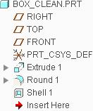
48 Many Ways to Model a Box 48
49 Making Design Intent Clear (1) Plan ahead Just doing it may be fast, but changing it not Unplanned models will slow down downstream engineering activities Use test models Test different approaches Destroy when not needed Models needs to have a purpose Model for showing ideas is not the model planed for design 49


50 Making Design Intent Clear (2) One feature per function If part is symmetric, use symmetry If you need many holes, pattern them 50


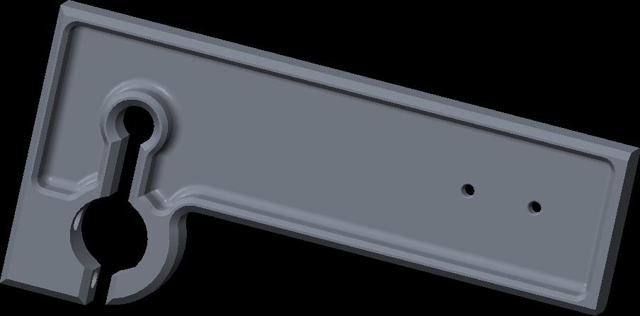
51 One Function per Feature Makes understanding and changing the model easier Raw material Hole for the axel Cut for the belt Belt Wheel 51

52 Right Tool for the Task One tool can do the trick But how about flexibility? 52
53 Ultimate Goal Increase speed of delivery Reduce cost Increase your value Speed up the iteration cycle Communicate better Make your life easier 53
54 The Hard Part There is no one right way to do things Your skill will increase, you will get better This is why we have exercises Take time to clean up your mistakes Do not be afraid to change a bad solution 54
55 Software
56 Main CAD program Current version PTC Creo Parametric 3.0 M050 Can be found CAE class (K344, K1, 3 rd floor) - Our teaching class CAD class (K345) - Next to CAE class Maari-B, -E and -K - Classes in Maarintalo 56
57 Creo Student Edition Possibility to install Creo 3.0 to your home computer Download link Deal between you and PTC - All support through them Customization files available at MyCourses - Use those to make your Creo behave like in our teaching classes Differences to University Edition - No Simulate - No Mankin - No Illustrate - No Schematics 57


58 How not to Make a Sphere Round and chamfer are not industrial design tools! Rounds 58
Computer Aided Design Basic Course
 Kon-41.3006 Computer Aided Design Basic Course 23 th September 2016 Agenda Practical Arrangements Parametric Modeling Software 2 Practical Arrangements Course Staff kaur.jaakma@aalto.fi Responsible Teacher
San José State University Aerospace Engineering AE20 Computer-Aided Design for Aerospace Engineers, Fa
 San José State University Aerospace Engineering AE20 Computer-Aided Design for Aerospace Engineers, Fa11 2017 Instructor: Office Location: Robert Benzio E407 Telephone: (408) 203-0457 Email: Office Hours:
NX 7.5. Table of Contents. Lesson 3 More Features
 NX 7.5 Lesson 3 More Features Pre-reqs/Technical Skills Basic computer use Completion of NX 7.5 Lessons 1&2 Expectations Read lesson material Implement steps in software while reading through lesson material
COURSE CONTENTS FOR THE AVTS COURSES
 Revision: 00 LEARNING CONTENT Page 1 of 14 COURSE CONTENTS FOR THE AVTS COURSES AT CAD- CAM LAB, ATI, VIDYANAGAR, HYDERABAD Revision: 00 LEARNING CONTENT Page 2 of 14 III COURSE CODE CAD-01 IV COURSE TITLE
CREO.1 MODELING A BELT WHEEL
 CREO.1 MODELING A BELT WHEEL Figure 1: A belt wheel modeled in this exercise. Learning Targets In this exercise you will learn: Using symmetry when sketching Using pattern to copy features Using RMB when
Creo Parametric Primer
 PTC Creo Parametric - Primer Student and Academic Editions 02 Helpful hints are enclosed in red brackets or round bubbles like this one! Creo Parametric Primer THIS VERSION OF THE CREO PRIMER HAS BEEN
Lesson Plans 5/13/13 5/17/13. Art 1: Perspective & Surreal Interiors Painting & Drawing: Perspective Paintings & Drawings
 Lesson Plans 5/13/13 5/17/13 Art 1: Perspective & Surreal Interiors Painting & Drawing: Perspective Paintings & Drawings Mon 5/13 A2, A4, AB5 Warm up: What is Perspective? Perspective is used to make objects
Parametric Modeling with Creo Parametric 2.0
 Parametric Modeling with Creo Parametric 2.0 An Introduction to Creo Parametric 2.0 Randy H. Shih SDC PUBLICATIONS Schroff Development Corporation Better Textbooks. Lower Prices. www.sdcpublications.com
Table of Contents. Lesson 1 Getting Started
 NX Lesson 1 Getting Started Pre-reqs/Technical Skills Basic computer use Expectations Read lesson material Implement steps in software while reading through lesson material Complete quiz on Blackboard
CAD-CAM-CAE Examples
 CAD-CAM-CAE Examples example title: example number: example level: CAx system: Related material part with TÁMOP Job Description: Shaft type component (CAD) ÓE-A06a basic - medium - advanced CATIA v5 CAD
1. Open the Feature Modeling demo part file on the EEIC website. Ask student about which constraints needed to Fully Define.
 BLUE boxed notes are intended as aids to the lecturer RED boxed notes are comments that the lecturer could make Control + Click HERE to view enlarged IMAGE and Construction Strategy he following set of
Creo Parametric 4.0 Basic Design
 Creo Parametric 4.0 Basic Design Contents Table of Contents Introduction...1 Objective of This Textbook...1 Textbook Outline...2 Textbook Conventions...3 Exercise Files...3 System Configuration...4 Notes
ENGINEERING. Unit 10 Computer Aided Design (CAD) 2016 Suite. Cambridge TECHNICALS LEVEL 3
 2016 Suite. Cambridge TECHNICALS LEVEL 3") 2016 Suite Cambridge TECHNICALS LEVEL 3 ENGINEERING Unit 10 Computer Aided Design (CAD) T/506/7276 Guided learning hours: 60 VERSION 4 - June 2017 black line indicates updated content ocr.org.uk/engineering
2016 Suite Cambridge TECHNICALS LEVEL 3 ENGINEERING Unit 10 Computer Aided Design (CAD) T/506/7276 Guided learning hours: 60 VERSION 4 - June 2017 black line indicates updated content ocr.org.uk/engineering
Autodesk Inventor 11 Certified User and Expert Exam Preparation Class [Part 1]
![Autodesk Inventor 11 Certified User and Expert Exam Preparation Class [Part 1]](/thumbs/74/69833255.jpg "Autodesk Inventor 11 Certified User and Expert Exam Preparation Class [Part 1]") 11/29/2006-3:00 pm - 4:30 pm Room:Marcello - 4404 (MSD Campus) Autodesk Inventor 11 Certified User and Expert Exam Preparation Class [Part 1] Daniel Banach - MasterGraphics MA24-2 Are you preparing to
11/29/2006-3:00 pm - 4:30 pm Room:Marcello - 4404 (MSD Campus) Autodesk Inventor 11 Certified User and Expert Exam Preparation Class [Part 1] Daniel Banach - MasterGraphics MA24-2 Are you preparing to
Parametric Design 1
 Western Technical College 10606115 Parametric Design 1 Course Outcome Summary Course Information Description Career Cluster Instructional Level Total Credits 3 This course is designed to introduce students
CAD EXERCISE 1.1 MODELING A SPIRAL STAIRCASE
 CAD EXERCISE 1.1 MODELING A SPIRAL STAIRCASE Figure 1: Spiral staircase and its model tree. Learning Targets In this exercise you will learn: Grouping features Using dimensional pattern Using relations
Custom Pillow Block Design Protrusion, Cut, Round, Draft (Review) Drawing (Review) Inheritance Feature (New) Creo 2.0
 Drawing (Review) Inheritance Feature (New) Creo 2.0") Custom Pillow Block Design Protrusion, Cut, Round, Draft (Review) Drawing (Review) Inheritance Feature (New) Creo 2.0 Rotatable pdf files: Casting Machining Grease Fitting Boss The general design of the
Custom Pillow Block Design Protrusion, Cut, Round, Draft (Review) Drawing (Review) Inheritance Feature (New) Creo 2.0 Rotatable pdf files: Casting Machining Grease Fitting Boss The general design of the
Parametric Modeling with
 Parametric Modeling with UGS NX 6 Randy H. Shih Oregon Institute of Technology SDC PUBLICATIONS Schroff Development Corporation www.schroff.com Better Textbooks. Lower Prices. Parametric Modeling with
Education Curriculum Combined Specialist
 Education Curriculum Combined Specialist Invest your time in imagining next generation designs. Here s what we will teach you to give shape to your imagination. CATIA Combined Specialist Course CATIA Mechanical
Mathematics Second Practice Test 1 Levels 3-5 Calculator not allowed
 Mathematics Second Practice Test 1 Levels 3-5 Calculator not allowed Please read this page, but do not open your booklet until your teacher tells you to start. Write your name and the name of your school
CATIA V5 Workbook Release V5-6R2013
 CATIA V5 Workbook Release V5-6R2013 Richard Cozzens SDC PUBLICATIONS Better Textbooks. Lower Prices. www.sdcpublications.com Powered by TCPDF (www.tcpdf.org) Visit the following websites to learn more
Made Easy. Jason Pancoast Engineering Manager
 3D Sketching Made Easy Jason Pancoast Engineering Manager Today I have taught you to sketch in 3D. It s as easy as counting ONE, TWO, FIVE...er...THREE! When your sketch only lives in Y and in X, Adding
Student s Signature Completion Date. High School Teacher s Signature. Recommended Grade High School. CAD software used: CAM software used:
 Student s Name 2 Credits College Now/CTE Student Outcomes Checklist cocc.edu/departments/college-now/ Student s Signature Completion Date High School Teacher s Signature Recommended Grade High School CAD
Here are the standard pre-requisites for the training course. Potential students should have or completed the following prior to the class:
 Course: Solid Edge Fundamentals Duration: 5 days Version: ST8 At Course Completion Students will have learned how to utilize Solid Edge to design production level parametric (ordered) models of parts,
COMMIT REWARDED AND BE COMMITMENT LETTER
 COMMITMENT LETTER COMMIT AND BE REWARDED { FINISH THIS BLUE PRINT & YOU WILL BE ON YOUR WAY TO MAKING IT RAIN Congratulations on your decision to join the phenomenon we call RAIN. You will be exposed to
Drawing and Assembling
 Youth Explore Trades Skills Description In this activity the six sides of a die will be drawn and then assembled together. The intent is to understand how constraints are used to lock individual parts
CSWP Segment #1 Concept Review
 1 CSWP Segment #1 Concept Review Segment 1: (90 Minutes) Creating a part from a drawing Using linked dimensions and equations to aid in modeling Using equations to relate dimensions Updating parameters
Creo Parametric 2.0: Introduction to Solid Modeling. Creo Parametric 2.0: Introduction to Solid Modeling
 Creo Parametric 2.0: Introduction to Solid Modeling 1 2 Part 1 Class Files... xiii Chapter 1 Introduction to Creo Parametric... 1-1 1.1 Solid Modeling... 1-4 1.2 Creo Parametric Fundamentals... 1-6 Feature-Based...
SOLIDWORKS 2015 and Engineering Graphics
 SOLIDWORKS 2015 and Engineering Graphics An Integrated Approach Randy H. Shih SDC PUBLICATIONS Better Textbooks. Lower Prices. www.sdcpublications.com Powered by TCPDF (www.tcpdf.org) Visit the following
Computer Aided Design and Engineering (CAD)
") Oakland Community College 2017-2018 Catalog 1 Computer Aided Design and Engineering (CAD) CAD 1050 Geometric Dimensioning and Tolerancing (GD&T) This course is designed to cover the fundamentals as well
Oakland Community College 2017-2018 Catalog 1 Computer Aided Design and Engineering (CAD) CAD 1050 Geometric Dimensioning and Tolerancing (GD&T) This course is designed to cover the fundamentals as well
Feature-Based Modeling and Optional Advanced Modeling. ENGR 1182 SolidWorks 05
 Feature-Based Modeling and Optional Advanced Modeling ENGR 1182 SolidWorks 05 Today s Objectives Feature-Based Modeling (comprised of 2 sections as shown below) 1. Breaking it down into features Creating
Designing with Parametric Sketches
 Designing with Parametric Sketches by Cory McConnell In the world of 3D modeling, one term that comes up frequently is parametric sketching. Parametric sketching, the basis for 3D modeling in Autodesk
1. Respect yourself, your associates, and your school.
 Classroom rules Tuesday, August 30, 2011 2:16 PM Rules 1. Respect yourself, your associates, and your school. 2. Enter the room, be seated, and check the board before the bell rings. 3. 4. 5. 6. 7. Eyes
1 Sketching. Introduction
 1 Sketching Introduction Sketching is arguably one of the more difficult techniques to master in NX, but it is well-worth the effort. A single sketch can capture a tremendous amount of design intent, and
and Engineering Graphics
 SOLIDWORKS 2018 and Engineering Graphics An Integrated Approach Randy H. Shih SDC PUBLICATIONS Better Textbooks. Lower Prices. www.sdcpublications.com Powered by TCPDF (www.tcpdf.org) Visit the following
Virtual CAD Parts to Enhance Learning of Geometric Dimensioning and Tolerancing. Lawrence E. Carlson University of Colorado at Boulder
 Virtual CAD Parts to Enhance Learning of Geometric Dimensioning and Tolerancing Lawrence E. Carlson University of Colorado at Boulder Introduction Geometric dimensioning and tolerancing (GD&T) is an important
Introduction to Engineering Design. Part C College Credit Performance
 Introduction to Engineering Design Final Examination Part C College Credit Performance Spring 2007 Student Name: Date: Class Period: Total Points: /50 49 of 99 Page 1 of 9 DIRECTIONS: Complete each of
Introduction to ANSYS DesignModeler
 Lecture 4 Planes and Sketches 14. 5 Release Introduction to ANSYS DesignModeler 2012 ANSYS, Inc. November 20, 2012 1 Release 14.5 Preprocessing Workflow Geometry Creation OR Geometry Import Geometry Operations
Essentials of SOLIDWORKS 2015 (4+ Days) * Ve-I Bonus! * File Management + SimulationXpress
 * Ve-I Bonus! * File Management + SimulationXpress") Essentials of SOLIDWORKS 2015 (4+ Days) * Ve-I Bonus! * File Management + SimulationXpress Overview What is SOLIDWORKS? Interface Tour View Manipulation Provides some background info on the SOLIDWORKS
Essentials of SOLIDWORKS 2015 (4+ Days) * Ve-I Bonus! * File Management + SimulationXpress Overview What is SOLIDWORKS? Interface Tour View Manipulation Provides some background info on the SOLIDWORKS
COURSE TITLE: ENGINEERING DRAWING 2 GRADES LENGTH: FULL YEAR SCHOOLS: RUTHERFORD HIGH SCHOOL RUTHERFORD, NEW JERSEY DATE:
 COURSE TITLE: ENGINEERING DRAWING 2 GRADES 10-12 LENGTH: FULL YEAR SCHOOLS: RUTHERFORD HIGH SCHOOL RUTHERFORD, NEW JERSEY DATE: SPRING 2015 Engineering Drawing 2-2 Rutherford High School Rutherford, NJ
Siemens NX11 tutorials. The angled part
 Siemens NX11 tutorials The angled part Adaptation to NX 11 from notes from a seminar Drive-to-trial organized by IBM and GDTech. This tutorial will help you design the mechanical presented in the figure
Representation of features Geometric tolerances. Prof Ahmed Kovacevic
 ME 1110 Engineering Practice 1 Engineering Drawing and Design - Lecture 6 Representation of features Geometric tolerances Prof Ahmed Kovacevic School of Engineering and Mathematical Sciences Room C130,
Part Design Fundamentals
 Part Design Fundamentals 1 Course Presentation Objectives of the course In this course you will learn basic methods to create and modify solids features and parts Targeted audience New CATIA V5 Users 1
Lesson 6 2D Sketch Panel Tools
 Lesson 6 2D Sketch Panel Tools Inventor s Sketch Tool Bar contains tools for creating the basic geometry to create features and parts. On the surface, the Geometry tools look fairly standard: line, circle,
Computer Aided Design I
 Black Horse Pike Regional School District 580 Erial Road, Blackwood, NJ 08012 Computer Aided Design I COURSE OF STUDY Technology Department Written by: Ken Whalen, Steve Arena and Vince Mannino Date: May
CALEDONIAN COLLEGE OF ENGINEERING, MODULE HANDBOOK. Department of Mechanical & Industrial Engineering SULTANATE OF OMAN. Module Code M2H324726
 Module Code M2H324726 Engineering Graphics CALEDONIAN COLLEGE OF ENGINEERING, SULTANATE OF OMAN 2017-18 MODULE HANDBOOK Semester B Module Leader Mr. Pradeep Kumar Krishnan Module Tutors Prof Sudhir C.V.
Computer Aided Design Parametric Modelling
 Level: 2 Credit value: 10 Unit aim The use of computer aide design (CAD) systems in industry has become an essential part of the modern working environment. It is used at all stages of the design period,
Designing in Context. In this lesson, you will learn how to create contextual parts driven by the skeleton method.
 Designing in Context In this lesson, you will learn how to create contextual parts driven by the skeleton method. Lesson Contents: Case Study: Designing in context Design Intent Stages in the Process Clarify
Autodesk Fusion 360 Introduction to Parametric Modeling
 Autodesk Fusion 360 Introduction to Parametric Modeling Course Length: 5 days The Autodesk Fusion 360 Introduction to Parametric Modeling training course provides you with an understanding of the parametric
How to Reduce Stress in Parts. Week 2 Lecture
 How to Reduce Stress in Parts Week 2 Lecture https://tinyurl.com/ybe759hc What this lecture and guide cover: Lecture: Stress - revisited CAD Guide: Renaming features Sweeps Chamfers/ Fillets Symmetry Projection
T&E Express SCSU Mobile Lab Program
 T&E Express SCSU Mobile Lab Program Course : Industrial Technology 8 Science Strand and Substrand being addressed Develop a model to generate data for iterative testing and modification of a proposed object,
Part Design. Sketcher - Basic 1 13,0600,1488,1586(SP6)
") Part Design Sketcher - Basic 1 13,0600,1488,1586(SP6) In this exercise, we will learn the foundation of the Sketcher and its basic functions. The Sketcher is a tool used to create two-dimensional (2D)
Part Design Sketcher - Basic 1 13,0600,1488,1586(SP6) In this exercise, we will learn the foundation of the Sketcher and its basic functions. The Sketcher is a tool used to create two-dimensional (2D)
Parametric Modeling. with. Autodesk Inventor Randy H. Shih. Oregon Institute of Technology SDC
 Parametric Modeling with Autodesk Inventor 2009 Randy H. Shih Oregon Institute of Technology SDC PUBLICATIONS Schroff Development Corporation www.schroff.com Better Textbooks. Lower Prices. iii Table of
Drafting and Design 1A
 Syllabus Drafting and Design 1A Overview This one-semester course is intended as a practical, hands-on guide to help you understand the various techniques, standards, and tools used in drafting and design.
California College Preparatory Academy
 ο An Aspire Public School California College Preparatory Academy 6200 San Pablo Avenue, Oakland, CA 94608 Phone: (510) 658-2900 Dear Parents and Families, The time has come for 7 th Grade students to begin
Introduction to Autodesk Inventor for F1 in Schools (Australian Version)
") Introduction to Autodesk Inventor for F1 in Schools (Australian Version) F1 in Schools race car In this course you will be introduced to Autodesk Inventor, which is the centerpiece of Autodesk s Digital
Introduction to Autodesk Inventor for F1 in Schools (Australian Version) F1 in Schools race car In this course you will be introduced to Autodesk Inventor, which is the centerpiece of Autodesk s Digital
Basic Features. In this lesson you will learn how to create basic CATIA features. Lesson Contents: CATIA V5 Fundamentals- Lesson 3: Basic Features
 Basic Features In this lesson you will learn how to create basic CATIA features. Lesson Contents: Case Study: Basic Features Design Intent Stages in the Process Determine a Suitable Base Feature Create
ARCHITECT VECTORWORKS EIGHTH EDITION TUTORIAL MANUAL BY JONATHAN PICKUP
 CH EIGHTH EDITION TUTORIAL MANUAL BY JONATHAN PICKUP A M TO R I A L T TU EC IT UA L AR ARCHITECT N HTH EDITION EIG / / / / / / / / / / / / / / / / / / / / / / / / / / / / / / / / / / / / / / / / / / /
Sketching & Auto CAD (Computer Aided Design) - Mechanical Design
 - Mechanical Design") Western Technical College 10606113 Sketching & Auto CAD (Computer Aided Design) - Mechanical Design Course Outcome Summary Course Information Description Career Cluster Instructional Level Total Credits
Western Technical College 10606113 Sketching & Auto CAD (Computer Aided Design) - Mechanical Design Course Outcome Summary Course Information Description Career Cluster Instructional Level Total Credits
Welcome to the a Department of Engineering Education! ENGR 1182 Introduction to Engineering II Graphics 01
 Welcome to the a Department of Engineering Education! ENGR 1182 Introduction to Engineering II Graphics 01 Today s Objectives Teaching Team Introduction Course Structure & Expectations Course Syllabus
Mechanical Drawing. Unit 2 Study Guide for Chapters 6-10
 Mechanical Drawing Unit 2 Study Guide for Chapters 6-10 Chapter 6 Multiview Drawing Section 6.1 Understanding Orthographic Projection A. Technical Drawing: How can a technical drawing give more accurate
Creo Parametric 1.0. for Engineers and Designers. CADCIM Technologies 525 St. Andrews Drive Schererville, IN 46375, USA (www.cadcim.
 Creo Parametric 1.0 for Engineers and Designers CADCIM Technologies 525 St. Andrews Drive Schererville, IN 46375, USA (www.cadcim.com) Contributing Author Sham Tickoo Professor Department of Mechanical
CREO 4.0: MODEL BASED DEFINITION (MBD)
") CREO 4.0: MODEL BASED DEFINITION (MBD) Raphael Nascimento Product Manager PTC Creo 17 November, 2016 PTC Forum Europe Stuttgart, Germany Model Based Definition (MBD) AGENDA GD&T Advisor Questions? 2 Model
CREO 4.0: MODEL BASED DEFINITION (MBD) Raphael Nascimento Product Manager PTC Creo 17 November, 2016 PTC Forum Europe Stuttgart, Germany Model Based Definition (MBD) AGENDA GD&T Advisor Questions? 2 Model
MECHANICAL ENGINEERING AND DESIGN 2017/18 SEMESTER 1 MODULES
 Visual Communications ENG_4_542 Tuesday and Wednesday 2pm 4pm (Tues), 9.30am 11.30am (Weds) Students attend both sessions. The module aims a) to develop the capacities of observation and visualisation,
Lesson 4 Extrusions OBJECTIVES. Extrusions
 Lesson 4 Extrusions Figure 4.1 Clamp OBJECTIVES Create a feature using an Extruded protrusion Understand Setup and Environment settings Define and set a Material type Create and use Datum features Sketch
with Creo Parametric 4.0
 Parametric Modeling with Creo Parametric 4.0 An Introduction to Creo Parametric 4.0 NEW Contains a new chapter on 3D Printing Randy H. Shih SDC PUBLICATIONS Better Textbooks. Lower Prices. www.sdcpublications.com
M TE S Y S LT U A S S A
 Dress-Up Features In this lesson you will learn how to place dress-up features on parts. Lesson Contents: Case Study: Timing Chain Cover Design Intent Stages in the Process Apply a Draft Create a Stiffener
COMPUTER AIDED ENGINEERING DESIGN (BFF2612) PART DESIGN Sketch Based Features
 PART DESIGN Sketch Based Features") COMPUTER AIDED ENGINEERING DESIGN (BFF2612) PART DESIGN Sketch Based Features by Dr. Mohd Nizar Mhd Razali Faculty of Manufacturing Engineering mnizar@ump.edu.my MODELLING STRATEGIES Determine model type
COMPUTER AIDED ENGINEERING DESIGN (BFF2612) PART DESIGN Sketch Based Features by Dr. Mohd Nizar Mhd Razali Faculty of Manufacturing Engineering mnizar@ump.edu.my MODELLING STRATEGIES Determine model type
Activity 5.5a CAD Model Features Part 1
 Activity 5.5a CAD Model Features Part 1 Introduction In order to use CAD effectively as a design tool, the designer must have the skills necessary to create, edit, and manipulate a 3D model of a part in
ME Week 2 Project 2 Flange Manifold Part
 1 Project 2 - Flange Manifold Part 1.1 Instructions This project focuses on additional sketching methods and sketching commands. Revolve and Work features are also introduced. The part being modeled is
Computer Aided Drawing: An Overview
 Computer Aided Drawing: An Overview Dr. H. Hirani Department of Mechanical Engineering INDIAN INSTITUTE OF TECHNOLOGY BOMBAY Powai, Mumbai-76 hirani@me.iitb.ac.in Drawing: Machine/ Engineering/ Technical
Math 210: 1, 2 Calculus III Spring 2008
 Math 210: 1, 2 Calculus III Spring 2008 Professor: Pete Goetz CRN: 20128/20130 Office: BSS 358 Office Hours: Tuesday 4-5, Wednesday 1-2, Thursday 3-4, Friday 8-9, and by appointment. Phone: 826-3926 Email:
getting started The 40 Hour Teacher Workweek Club choose a target number of hours and stick to it
 getting started The 40 Hour Teacher Workweek Club choose a target number of hours and stick to it Welcome to the 40HTW Club! Before the club begins, you ll want to explore: q How I chose a 40 hour workweek
Autodesk Inventor 2016 Creating Sketches
 Autodesk Inventor 2016 Creating Sketches 2D Sketch Practice 1 1. Launch Autodesk Inventor 2016 2. Create a new Part file (.ipt) 3. Save File As a. Click on the save icon. b. Save you file onto your flash
Computer Aided Design and Engineering Technology
 Oakland Community College 2017-2018 Catalog 1 Computer Aided Design and Engineering Technology Degrees Computer Aided Engineering Option (CAD.CAE.AAS) (http:// catalog.oaklandcc.edu/programs/computer-aided-design-draftingtechnology/computer-aided-design-drafting-technology-engineeringoption-aas)
1. Creating geometry based on sketches 2. Using sketch lines as reference 3. Using sketches to drive changes in geometry
 4.1: Modeling 3D Modeling is a key process of getting your ideas from a concept to a read- for- manufacture state, making it core foundation of the product development process. In Fusion 360, there are
Test Code: 8294 / Version 1
 Pennsylvania Customized Assessment Blueprint Test Code: 8294 / Version 1 Copyright 2014. All Rights Reserved. General Assessment Information Blueprint Contents General Assessment Information Written Assessment
Tools for Design. with VEX Robot Kit: Randy H. Shih Oregon Institute of Technology SDC PUBLICATIONS
 Tools for Design with VEX Robot Kit: AutoCAD 2011 and Autodesk Inventor 2011 2D Drawing 3D Modeling Hand Sketching Randy H. Shih Oregon Institute of Technology INSIDE: SUPPLEMENTAL FILES ON CD SDC PUBLICATIONS
Computer Aided Drafting and Design
 Computer Aided Drafting and Design Degrees: AAS Computer Aided Drafting and Design 60-63 Diploma: Computer Aided Drafting and Design 48-51 Certificates: Computer Assisted Drafter 30-36 Detailer 25-28 Drafter
ENGINEERING TECHNOLOGIES ENGINEERING GRAPHICS & DESIGN/DRAFTING Associate in Applied Science: 75 Credit Hours
 ENGINEERING TECHNOLOGIES ENGINEERING GRAPHICS & DESIGN/DRAFTING Associate in Applied Science: 75 Credit Hours Prior Learning Assessment Opportunities ETDG 1143 Course Introduction to Design/Drafting ETDG
Advanced icopy Part Development in Autodesk Inventor-Complex Adaptive Geometry
 Advanced icopy Part Development in Autodesk Inventor-Complex Adaptive Geometry Cortney Sieben Enclos Corp Lab Assistants- William Graham, Enclos Corp / Michael Schumacher, Enclos Corp / Stan Wile, Imaginit
Design and Communication Graphics
 Design and Communication Graphics Scheme of Work 2014-2015 Ballyhaunis Community School Mission statement The DCG department aspires to provide a safe, stimulating environment where all students can develop
TTC Catalog - Engineering Graphics Technology (EGT)
") 2018-2019 TTC Catalog - Engineering Graphics Technology (EGT) EGT 001 - EGT 001 Lec: 0 Lab: 0 Credit: * Indicates credit given f engineering graphics course wk transferred from another college f which
2018-2019 TTC Catalog - Engineering Graphics Technology (EGT) EGT 001 - EGT 001 Lec: 0 Lab: 0 Credit: * Indicates credit given f engineering graphics course wk transferred from another college f which
Creo Parametric Primer
 Creo Parametric Primer Creo Parametric Primer Education Editions 2 C2-SE-L1-004-1.0 Written by Tim Brotherhood and Adam Haas Conditions of use Acknowledgements Feedback tbrotherhood@ptc.com Product code
Table of Contents. Dedication Preface. Chapter 1: Introduction to CATIA V5-6R2015. Chapter 2: Drawing Sketches in the Sketcher Workbench-I.
 Table of Contents Dedication Preface iii xvii Chapter 1: Introduction to CATIA V5-6R2015 Introduction to CATIA V5-6R2015 1-2 CATIA V5 Workbenches 1-2 System Requirements 1-4 Getting Started with CATIA
ENGINEERING GRAPHICS. Lecture 1: Introduction to Graphic Communication. Jazmin Ley University of Texas Rio Grande Valley
 ENGINEERING GRAPHICS Lecture 1: Introduction to Graphic Communication Jazmin Ley University of Texas Rio Grande Valley Overview Graphics Communication in the Design Process Engineering Design Process:
Working with Detail Components and Managing DetailsChapter1:
 Chapter 1 Working with Detail Components and Managing DetailsChapter1: In this chapter, you learn how to use a combination of sketch lines, imported CAD drawings, and predrawn 2D details to create 2D detail
Activity Pegboard Toy
 Activity 1.5.5 Pegboard Toy Purpose When you receive a toy, what is the first thing you wonder about it? Do you wonder how it works? Have you ever wondered who designed it or who may have made decisions
COURSE OUTLINE. Course Number Course Title Credits. Co- or Pre-requisite BCT110 Construction Materials & Methods
 COURSE OUTLINE Course Number Course Title Credits BCT101 Construction Graphics 3 Hours: 2 Lecture 2 Studio/Lab, Co- or Pre-requisite BCT110 Construction Materials & Methods Implementation sem/year Fall
1/20/2017. Warmup 1/ Check Homework. Methods of studying. Return Quizzes
 Created by Mr. Lischwe Warmup 1/ 2 10 1 1. Copy the diagram. How many rectangles of any size are there? A square counts as a rectangle. Check Homewk Return Quizzes Retake deadline is on the board! I chose
EG - Engineering Graphics
 Coordinating unit: 205 - ESEIAAT - Terrassa School of Industrial, Aerospace and Audiovisual Engineering Teaching unit: 717 - EGE - Department of Engineering Presentation Academic year: Degree: 2018 BACHELOR'S
Using Think-Aloud Exercises to Reveal Students Solid Modeling Strategies
 Using Think-Aloud Exercises to Reveal Students Solid Modeling Strategies Jonathan Leith, Holly K. Ault Mechanical Engineering Department Worcester Polytechnic Institute Abstract This paper describes the
PENNSYLVANIA. List properties, classify, draw, and identify geometric figures in two dimensions.
 Know: Understand: Do: CC.2.3.4.A.1 -- Draw lines and angles and identify these in two-dimensional figures. CC.2.3.4.A.2 -- Classify twodimensional figures by properties of their lines and angles. CC.2.3.4.A.3
ME-441 COMPUTER SIMULATION AND ANALYSIS
 ME-441 COMPUTER SIMULATION AND ANALYSIS IN MECHANICAL ENGINEERING Instructor: Dr. Herli Surjanhata Mechanical Engineering Department Office: 328 MEC Phone: (973) 596-3317 e-mail: surjanhata@adm.njit.edu
Learning. Autodesk Inventor 2019 SDC. Modeling, Assembly and Analysis. Randy H. Shih. Better Textbooks. Lower Prices.
 Learning Autodesk Inventor 2019 Modeling, Assembly and Analysis Randy H. Shih SDC PUBLICATIONS Better Textbooks. Lower Prices. www.sdcpublications.com Powered by TCPDF (www.tcpdf.org) Visit the following
Creo Extrude Tutorial 2: Cutting and Adding Material
 Creo Extrude Tutorial 2: Cutting and Adding Material 1. Open Creo Parametric 2. File > Open > extrudeturial (From Creo Extrude Tutorial 1) 3. Cutting Material a. Click Extrude Icon > Select the following
Fits and Tolerances. Prof Ahmed Kovacevic
 ME 1110 Engineering Practice 1 Engineering Drawing and Design - Lecture 7 Fits and Tolerances Prof Ahmed Kovacevic School of Engineering and Mathematical Sciences Room C130, Phone: 8780, E-Mail: a.kovacevic@city.ac.uk
Universidad Autónoma de San Luis Potosí Collegue of Engineering Mechanical and Electrical Department Analytical Program
 A) COURSE Course Id: Course 5689 Computer Aided Design Class Hours per Week Lab hours per week Complementary Credits Total hour practices course 0 3 0 3 48 hrs. B) GENERAL COURSE INFORMATION: EE (IEA)
Objectives. Inventor Part Modeling MA 23-1 Presented by Tom Short, P.E. Munro & Associates, Inc
 Objectives Inventor Part Modeling MA 23-1 Presented by Tom Short, P.E. Munro & Associates, Inc To demonstrate most of the sketch tools and part features in : Inventor Release 6 And, to show logical techniques
Training Guide Basics
 Training Guide Basics 2014, Missler Software. 7, Rue du Bois Sauvage F-91055 Evry, FRANCE Web: www.topsolid.com E-mail: info@topsolid.com All rights reserved. TopSolid Design Basics This information is