Jonathan R. Torch Senior Thesis Final Report Columbia University. Appendix A. Structural Depth Appendix (with Commentary)
|
|
|
- Annabelle Stephens
- 5 years ago
- Views:
Transcription

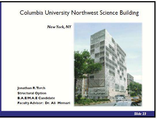
1 Appendix A Structural Depth Appendix (with Commentary) Columbia University Northwest Science Building Broadway & 120 th Street, New York, NY Pennsylvania State University Page 69 of 122
2 evation This Structural Depth Appendix Section will provide commentary along with some of the tables, graphs, images, and figures. The commentary is intended to give the reader a better understanding of the process in which the lateral system was analyzed and redesigned. Pennsylvania State University Page 70 of 122
3 evation The following tables provide excel spreadsheet calculations for determining the wind forces acting upon the building in Miami, FL. These calculations conclude with story forces, story shear, and overturning moment values. Table 4A: Wind North-South Direction Level Height (Feet) Tributary Area(Feet) K z q z = K z K zt K d V 2 I K h q h = K h K zt K d V 2 I Roof(15) M M M M M M M M M Ground(1) Pennsylvania State University Page 71 of 122
4 Table 4B: Wind North-South Direction Continued Level Windward(psf) Leeward(psf) Total(psf) StoryForce (kips) StoryShear (kips) Overturning Moment(ftkips) Roof(15) M M M M M M M M M Ground(1) Pennsylvania State University Page 72 of 122
5 Table 5A: Wind East-West Direction Level Height (Feet) Tributary Area(Feet) K z q z = K z K zt K d V 2 I K h q h = K h K zt K d V 2 I Roof(15) M M M M M M M M M Ground(1) Pennsylvania State University Page 73 of 122
6 Table 5B: Wind East-West Direction Continued Windward(psf) Leeward(psf) Total(psf) StoryForce (kips) StoryShear (kips) Overturning Moment(ftkips) evation Pennsylvania State University Page 74 of 122
7 evation Table 6: Un-factored Story Forces for ETABS Deflection Wind Analysis XDirectionStoryForces(kips) YDirectionStoryForces(kips) Level Level Roof(15) Roof(15) M M M M M M M M M M M M M M M M M M Pennsylvania State University Page 75 of 122
8 evation Before the calculated wind forces are inputted into ETABS and analyzed, the author wanted to make sure the structure s lateral system was modeled accurately using ETABS software. An accurate modeled structure will consist of the proper connections, mass, member sizes, member properties, and geometric inputs. The structure is very complex, and it is suspected by the author that it will not be modeled 100% accurate. However, to confirm the validity of the model, the main period of the building will be checked. Below shows the comparison of an estimated code calculation yielding 1.75 seconds, and the ETABS analysis yielding 2.11 seconds. These values are relatively close to one another, ensuring the author that the ETABS model inputs are accurate enough for this thesis study. Pennsylvania State University Page 76 of 122
9 Table 9: East-West Direction Wind Serviceability Checks (Existing Design) Grid1Wind(ServicabilityChecks) Grid2Wind(ServicabilityChecks) Grid3Wind(ServicabilityChecks) STORY DISPX(IN) STORYDRIFT(IN) STORY DISPX(IN) STORYDRIFT(IN) STORY DISPX(IN) STORYDRIFT(IN) LEVEL LEVEL LEVEL LEVEL14M LEVEL14M LEVEL14M LEVEL LEVEL LEVEL LEVEL13M LEVEL13M LEVEL13M LEVEL LEVEL LEVEL LEVEL12M LEVEL12M LEVEL12M LEVEL LEVEL LEVEL LEVEL11M LEVEL11M LEVEL11M LEVEL LEVEL LEVEL LEVEL10M 9.19 LEVEL10M 9.20 LEVEL10M LEVEL LEVEL LEVEL LEVEL9M 8.33 LEVEL9M 8.32 LEVEL9M LEVEL LEVEL LEVEL LEVEL8M 7.08 LEVEL8M 7.12 LEVEL8M LEVEL LEVEL LEVEL LEVEL7M 5.12 LEVEL7M 5.16 LEVEL7M LEVEL LEVEL LEVEL LEVEL6M 3.46 LEVEL6M 3.57 LEVEL6M LEVEL LEVEL LEVEL LEVEL LEVEL LEVEL LEVEL LEVEL LEVEL LEVEL LEVEL LEVEL LEVEL LEVEL LEVEL Grid4Wind(ServicabilityChecks) Grid10Wind(ServicabilityChecks) STORY DISPX(IN) STORYDRIFT(IN) STORY DISPX(IN) STORYDRIFT(IN) LEVEL LEVEL LEVEL14M LEVEL14M LEVEL LEVEL LEVEL13M LEVEL13M LEVEL LEVEL LEVEL12M LEVEL12M LEVEL LEVEL LEVEL11M LEVEL11M LEVEL LEVEL LEVEL10M 9.23 LEVEL10M LEVEL LEVEL LEVEL9M 8.36 LEVEL9M LEVEL LEVEL LEVEL8M 7.13 LEVEL8M LEVEL LEVEL LEVEL7M 5.29 LEVEL7M LEVEL LEVEL LEVEL6M 3.79 LEVEL6M LEVEL LEVEL LEVEL LEVEL LEVEL LEVEL LEVEL LEVEL LEVEL LEVEL evation Above is ETABS analysis output data for drift and story drift checks. This output data was obtained by loading the lateral system in the East-West direction using unfactored loads (for serviceability checks). As shown above the existing design is deflecting a great amount due to the increase wind loads of Miami, FL. This occurrence is similar to the North-South direction existing analysis. (Table can be found on the following page.) Pennsylvania State University Page 77 of 122
10 Table 10: North-South Direction Wind Serviceability Checks (Existing Design) GridAWind(ServicabilityChecks) GridCWind(ServicabilityChecks) STORY DISPY(IN) STORYDRIFT(IN) STORY DISPY(IN) STORYDRIFT(IN) LEVEL LEVEL LEVEL14M LEVEL14M LEVEL LEVEL LEVEL13M 2.25 LEVEL13M LEVEL LEVEL LEVEL12M 1.94 LEVEL12M LEVEL LEVEL LEVEL11M 1.61 LEVEL11M LEVEL LEVEL LEVEL10M 1.37 LEVEL10M LEVEL LEVEL LEVEL9M 1.14 LEVEL9M LEVEL LEVEL LEVEL8M 0.95 LEVEL8M LEVEL LEVEL LEVEL7M 0.73 LEVEL7M LEVEL LEVEL LEVEL6M 0.59 LEVEL6M LEVEL LEVEL LEVEL LEVEL LEVEL LEVEL LEVEL LEVEL LEVEL LEVEL GridDWind(ServicabilityChecks) STORY DISPY(IN) STORYDRIFT(IN) LEVEL LEVEL14M LEVEL LEVEL13M LEVEL12M LEVEL11M LEVEL10M LEVEL9M LEVEL8M LEVEL7M LEVEL6M LEVEL5 LEVEL LEVEL13 LEVEL12 LEVEL11 LEVEL10 LEVEL9 LEVEL8 LEVEL7 LEVEL6 LEVEL4 LEVEL Pennsylvania State University Page 78 of 122
11 Table 14: East-West Direction Wind Serviceability Checks (Redesign System) Grid1Wind(ServicabilityChecks) Grid2Wind(ServicabilityChecks) Grid3Wind(ServicabilityChecks) STORY DISPX(IN) STORYDRIFT(IN) STORY DISPX(IN) STORYDRIFT(IN) STORY DISPX(IN) STORYDRIFT(IN) LEVEL LEVEL LEVEL LEVEL14M LEVEL14M LEVEL14M LEVEL LEVEL LEVEL LEVEL13M 6.47 LEVEL13M 6.43 LEVEL13M LEVEL LEVEL LEVEL LEVEL12M 5.78 LEVEL12M 5.91 LEVEL12M LEVEL LEVEL LEVEL LEVEL11M 5.10 LEVEL11M 5.22 LEVEL11M LEVEL LEVEL LEVEL LEVEL10M 4.42 LEVEL10M 4.36 LEVEL10M LEVEL LEVEL LEVEL LEVEL9M 3.65 LEVEL9M 3.74 LEVEL9M LEVEL LEVEL LEVEL LEVEL8M 2.93 LEVEL8M 3.05 LEVEL8M LEVEL LEVEL LEVEL LEVEL7M 2.26 LEVEL7M 2.26 LEVEL7M LEVEL LEVEL LEVEL LEVEL6M 1.59 LEVEL6M 1.63 LEVEL6M LEVEL LEVEL LEVEL LEVEL LEVEL LEVEL LEVEL LEVEL LEVEL LEVEL LEVEL LEVEL LEVEL LEVEL LEVEL Grid4Wind(ServicabilityChecks) Grid10Wind(ServicabilityChecks) STORY DISPX(IN) STORYDRIFT(IN) STORY DISPX(IN) STORYDRIFT(IN) LEVEL LEVEL LEVEL14M LEVEL14M LEVEL LEVEL LEVEL13M 6.46 LEVEL13M LEVEL LEVEL LEVEL12M 5.91 LEVEL12M LEVEL LEVEL LEVEL11M 5.13 LEVEL11M LEVEL LEVEL LEVEL10M 4.30 LEVEL10M LEVEL LEVEL LEVEL9M 3.70 LEVEL9M LEVEL LEVEL LEVEL8M 2.97 LEVEL8M LEVEL LEVEL LEVEL7M 2.24 LEVEL7M LEVEL LEVEL LEVEL6M 1.61 LEVEL6M LEVEL LEVEL LEVEL LEVEL LEVEL LEVEL LEVEL LEVEL LEVEL LEVEL evation Above is ETABS analysis output data for drift and story drift checks. This output data was obtained by loading the lateral system in the East-West direction using unfactored loads (for serviceability checks). As shown above the redesign lateral system now meets serviceability requirements under Miami, FL wind loading. This holds true for the North-South direction redesigned system analysis. (Table can be found on following page.) Pennsylvania State University Page 79 of 122
12 Table 15: North-South Direction Wind Serviceability Checks (Redesigned System) GridAWind(ServicabilityChecks) GridCWind(ServicabilityChecks) STORY DISPY(IN) STORYDRIFT(IN) STORY DISPY(IN) STORYDRIFT(IN) LEVEL LEVEL LEVEL14M LEVEL14M LEVEL LEVEL LEVEL13M 1.14 LEVEL13M LEVEL LEVEL LEVEL12M 1.09 LEVEL12M LEVEL LEVEL LEVEL11M 1.01 LEVEL11M LEVEL LEVEL LEVEL10M 0.91 LEVEL10M LEVEL LEVEL LEVEL9M 0.80 LEVEL9M LEVEL LEVEL LEVEL8M 0.71 LEVEL8M LEVEL LEVEL LEVEL7M 0.64 LEVEL7M LEVEL LEVEL LEVEL6M 0.60 LEVEL6M LEVEL LEVEL LEVEL LEVEL LEVEL LEVEL LEVEL LEVEL LEVEL LEVEL GridDWind(ServicabilityChecks) STORY DISPY(IN) STORYDRIFT(IN) LEVEL LEVEL14M LEVEL LEVEL13M LEVEL12M LEVEL11M LEVEL10M LEVEL9M LEVEL8M LEVEL7M LEVEL6M LEVEL5 LEVEL LEVEL13 LEVEL12 LEVEL11 LEVEL10 LEVEL9 LEVEL8 LEVEL7 LEVEL6 LEVEL4 LEVEL Pennsylvania State University Page 80 of 122

13 A strength check of the existing structure for Miami, FL wind forces is provided below. This strength check yields a failed member. This failure is one example of several occurrences throughout the existing lateral system. Pennsylvania State University Page 81 of 122
14 Below is an ETABS printout of axial forces in Grid A for its controlling wind force case. These members were checked by the author and redesign appropriately if a larger section was needed for tension or compression requirements. Pennsylvania State University Page 82 of 122
15 Below is an ETABS printout of mainly compressive forces in Grid A. Grid A is in the North-South direction of the lateral system. Grids A, C, & D have lateral members that are loaded under both wind and dead load forces. Combinations of these forces are analyzed to check the design of column and brace frame members. Pennsylvania State University Page 83 of 122
16 Below is example hand calculation checks performed for Grid A. Pennsylvania State University Page 84 of 122
17 Analysis and preliminary design of Grid C followed the same process as shown previously for Grid A. Pennsylvania State University Page 85 of 122
18 Pennsylvania State University Page 86 of 122
19 The East-West direction preliminary design came next. This redesign was extensive and did not just involve checking existing member s sizes, which was performed in the North-South direction grids. Pennsylvania State University Page 87 of 122
20 Below is a preliminary design of Grid 1 bracing members. The members were treated as concentric (axial loaded) members. Member sizes were chosen appropriately using the LRFD (Load & Resistance Factor Design) manual. Pennsylvania State University Page 88 of 122
21 After member changes were performed, the ETABS model was analyzed, once again. Members that did not meet capacity demands were noted and redesign appropriately. This process continued until a sufficient design was attainable. Pennsylvania State University Page 89 of 122
22 Additional hand calculated checks (Grid 1) were performed to provide validity of the ETABS analysis. Pennsylvania State University Page 90 of 122
23 Analysis and redesign of Grid 4 followed similarly to Grid 1. Take notice that Grid 4 is an interior grid and therefore contains one bay chevron bracing to fulfill architectural spatial needs. Pennsylvania State University Page 91 of 122
24 Preliminary sizing of Grid 4 members is shown below. Pennsylvania State University Page 92 of 122
25 Capacity check of Grid 4 is shown below. Highlighted members did not meet capacity demands and were redesigned once again. Pennsylvania State University Page 93 of 122
26 Hand calculated checks of Grid 4 redesign is shown below and on the following page. Pennsylvania State University Page 94 of 122
27 Pennsylvania State University Page 95 of 122
28 Analysis and redesign of Grid 10 followed similarly to Grids 1 & 4. Pennsylvania State University Page 96 of 122
29 Capacity check of Grid 10 is shown below. Highlighted members did not meet capacity demands and were redesigned once again. Pennsylvania State University Page 97 of 122
30 Hand calculated checks of Grid 10 redesign is shown below. Pennsylvania State University Page 98 of 122
31 Finalized Member Sizes: evation The following pages provide images of all the participating grids of the redesigned lateral system. These images provide finalized member sizes for each grid. Please note that these member sizes were determined through a repetitive analysis process, which is explained in the following paragraph. This process utilized ETABS software to analyze each grid under its governing wind case. Forces and stresses were found using the calculated wind forces and ETABS analysis. From these forces and stresses, member sizes could be chosen appropriately. When several member sizes were designed, the stiffness of a participating grid would change relative to the entire lateral system. This would cause a redistribution of lateral forces to each grid. This is why the lateral system was designed using a repetitive process, until distribution of lateral forces to grids remained relatively constant. The finalized grid designs of the lateral system were obtained only after each passed drift, story drift, and strength requirements. Pennsylvania State University Page 99 of 122

32 Grid 1 Finalized Member Sizes Pennsylvania State University Page 100 of 122

33 Grid 4 Finalized Member Sizes Pennsylvania State University Page 101 of 122
34 Grid 10 Finalized Member Sizes Pennsylvania State University Page 102 of 122
35 Grid A Finalized Member Sizes Pennsylvania State University Page 103 of 122
36 Grid C Finalized Member Sizes Pennsylvania State University Page 104 of 122

37 Grid D Finalized Member Sizes Pennsylvania State University Page 105 of 122

38 Appendix B Existing Plans, Elevations, & Sections Columbia University Northwest Science Building Broadway & 120 th Street, New York, NY Pennsylvania State University Page 106 of 122

39 Lateral System Frame Elevations GRID 1 GRIDS 2-4 GRID 10 Pennsylvania State University Page 107 of 122


40 Typical Floor Plan Pennsylvania State University Page 108 of 122

41 North Building Elevation West Building Elevation Pennsylvania State University Page 109 of 122

42 South Building Elevation East Building Elevation Pennsylvania State University Page 110 of 122

43 Appendix C Cost Analyses Calculations & Data Columbia University Northwest Science Building Broadway & 120 th Street, New York, NY Pennsylvania State University Page 111 of 122
44 The following two pages provide a cost analysis for the Building Enclosure Breadth s Study. This study was able to reduce the insulation layer of the building enclosure from 4 to 2.5. Pennsylvania State University Page 112 of 122

45 Pennsylvania State University Page 113 of 122

46 Appendix D Thesis Presentation Slides Columbia University Northwest Science Building Broadway & 120 th Street, New York, NY Pennsylvania State University Page 114 of 122

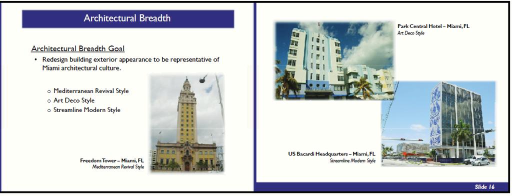
47 Pennsylvania State University Page 115 of 122
48 Pennsylvania State University Page 116 of 122

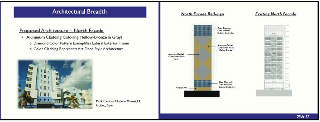
49 Pennsylvania State University Page 117 of 122

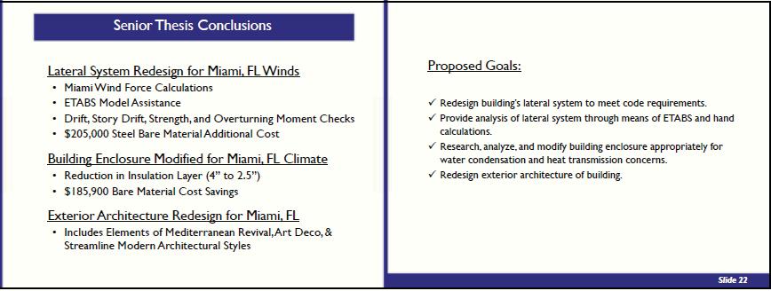
50 Pennsylvania State University Page 118 of 122

51 Pennsylvania State University Page 119 of 122
52 Pennsylvania State University Page 120 of 122

53 Pennsylvania State University Page 121 of 122
54 Pennsylvania State University Page 122 of 122
General Layout. Eng. Maha Moddather
 General Layout Eng. Maha Moddather mahamoddather@eng.cu.edu.eg Introduction Concrete Beam subjected to Bending Moment around Major Axis M x Compression d Concrete tensile strength is neglected A S Tension
K L Rakshith, Smitha, International Journal of Advance Research, Ideas and Innovations in Technology.
 ISSN: 2454-132X Impact factor: 4.295 (Volume3, Issue4) Available online at www.ijariit.com Effect of Bracings on Multistored RCC Frame Structure under Dynamic Loading Rakshith K L Department of Civil Engineering
Effect of Infill Walls on RC Framed Structure
 Effect of Infill Walls on RC Framed Structure Akshay Grover 1, Dr. S.K. Verma 2 P.G. Student, Department of Civil Engineering (Structures), PEC University of Technology, Chandigarh, India 1 Associate Professor,
Lesson 17. The Focus of this lesson is:
 The Focus of this lesson is: Inserting beams between frames to support Roof Top Units or concentrated loads Loading the roof beams so they design Locating a roof framed opening Lesson Comments: This lesson
Effect of Masonry Infills on Seismic Performance of RC Frame Buildings
 Effect of Masonry Infills on Seismic Performance of RC Frame Buildings Dev Raj Paudel 1, Santosh Kumar Adhikari 2 P.G. Student, Department of Civil Engineering, Andhra University, Visakhapatnam, Andhra
Seismic Response of Cellwise Braced Reinforced Concrete Frames
 International Journal of Current Engineering and Technology E-ISSN 2277 4106, P-ISSN 2347 5161 2015INPRESSCO, All Rights Reserved Available at http://inpressco.com/category/ijcet Research Article Kulkarni
ASSESSMENT OF BASIC STEEL I-SECTION BEAM BRACING REQUIREMENTS BY TEST SIMULATION
 ASSESSMENT OF BASIC STEEL I-SECTION BEAM BRACING REQUIREMENTS BY TEST SIMULATION A Thesis By Evan P. Prado In Partial Fulfillment Of the Requirements for the Degree Master of Science in Civil Engineering
Section Downloads. Terminology Outline. Industry Standards/ Publications. American Softwood Lumber Standard ANSI/TPI 1. Section 02: Terminology
 Section Downloads Download & Print TTT I Sec 02 Slides TTT I Sec 02 Handouts Version 2.1 Section 02: Terminology 1 2 Terminology Outline Industry Standards/Publications Truss Terms Bracing Terms Design
A Study On Bracing Systems On High Rise Steel Structures Jagadish J. S [1], Tejas D. Doshi [2]
![A Study On Bracing Systems On High Rise Steel Structures Jagadish J. S [1], Tejas D. Doshi [2]](/thumbs/94/118705636.jpg "A Study On Bracing Systems On High Rise Steel Structures Jagadish J. S [1], Tejas D. Doshi [2]") Abstract A Study On Bracing Systems On High Rise Steel Structures Jagadish J. S [1], Tejas D. Doshi [2] 1-Post Graduate Student, Department of Civil Engineering, KLE Dr. MSSCET, Belgaum, Karnataka, India,
Abstract A Study On Bracing Systems On High Rise Steel Structures Jagadish J. S [1], Tejas D. Doshi [2] 1-Post Graduate Student, Department of Civil Engineering, KLE Dr. MSSCET, Belgaum, Karnataka, India,
Changes in the 2001 NDS for Wood Construction
 Changes in the 2001 NDS for Wood Construction Philip Line, P.E.; Dr. Robert Taylor, P.Eng.; John Buddy Showalter, P.E.; Bradford K. Douglas, P.E. Introduction The 2001 Edition of the National Design Specification
3.1 General Provisions
 WOOD FRAME CONSTRUCTION MANUAL 107 3.1 General Provisions 3.1.1 Prescriptive Requirements The provisions of this Chapter establish a specific set of resistance requirements for buildings meeting the scope
Shinde Suyog Sudhakar, Galatage Abhijeet.A, Kulkarni Sumant.K, International Journal of Advance Research, Ideas and Innovations in Technology.
 ISSN: 2454-132X Impact factor: 4.295 (Volume3, Issue5) Available online at www.ijariit.com Evaluating Seismic Efficiency of Combination of Bracing for Steel Building Suyog Sudhakar Shinde 1P. G. Student
nineteen Wood Construction 1 and design APPLIED ARCHITECTURAL STRUCTURES: DR. ANNE NICHOLS FALL 2016 lecture STRUCTURAL ANALYSIS AND SYSTEMS ARCH 631
 APPLIED ARCHITECTURAL STRUCTURES: STRUCTURAL ANALYSIS AND SYSTEMS DR. ANNE NICHOLS FALL 2016 lecture nineteen wood construction and design Wood Construction 1 Timber Construction all-wood framing systems
EFFECT OF SETBACK RATIO ON SEISMIC PERFORMANCE OF RC STRUCTURES
 International Research Journal of Engineering and Technology (IRJET) e-issn: - EFFECT OF SETBACK RATIO ON SEISMIC PERFORMANCE OF RC STRUCTURES Shambhavi B. Hiremath, M.E. Raghu and Dr. G. Chidananda Student,
Module 1: Building Model Creation
 INSTRUCTIONAL MODULES DEMONSTRATING BUILDING ENERGY ANALYSIS USING A BUILDING INFORMATION MODEL Christian Daniel Douglass Industrial and Enterprise Systems Engineering December 1, 2010 Module Summary In
2016 AASHTO BRIDGE COMMITTEE AGENDA ITEM: 24 (REVISION 1) SUBJECT: LRFD Bridge Design Specifications: Section 6, Various Articles (2)
 SUBJECT: LRFD Bridge Design Specifications: Section 6, Various Articles (2)") 2016 AASHTO BRIDGE COMMITTEE AGENDA ITEM: 24 (REVISION 1) SUBJECT: LRFD Bridge Design Specifications: Section 6, Various Articles (2) TECHNICAL COMMITTEE: T-14 Steel REVISION ADDITION NEW DOCUMENT DESIGN
2016 AASHTO BRIDGE COMMITTEE AGENDA ITEM: 24 (REVISION 1) SUBJECT: LRFD Bridge Design Specifications: Section 6, Various Articles (2) TECHNICAL COMMITTEE: T-14 Steel REVISION ADDITION NEW DOCUMENT DESIGN
Total precast solution for large stadium projects meet tight schedule
 Tailor Made Concrete Structures Walraven & Stoelhorst (eds) 2008 Taylor & Francis Group, London, ISBN 978-0-415-47535-8 Total precast solution for large stadium projects meet tight schedule T.J. D Arcy
REINFORCEMENT DESIGN FOR METAL BUILDING SYSTEMS
 REINFORCEMENT DESIGN FOR METAL BUILDING SYSTEMS By Donald L. Johnson, P.E. RETROFIT PROJECTS CAN BE NECESSARY FOR ANY NUMBER OF REASONS, though change in use is one of the most common. Change of use can
Moment Resisting Connections for Load Bearing Walls
 PRECAST: MOMENT RESISTING CONNECTIONS Moment Resisting Connections for Load Bearing Walls Manish Khandelwal Sr. Structural Engineer, Building Structures, Sweco India Private Limited Design philosophy for
This specification describes the minimum requirements for structural steel drawings.
 1/7 1.0 PURPOSE This specification describes the minimum requirements for structural steel drawings. 2.0 GENERAL As stated in specification SPEC-0800, drawings are intended to be Design drawings. Sufficient
Seismic Performance of Brick Infill in RCC Structure
 Seismic Performance of Brick Infill in RCC Structure Ms. Vaishnavi Battul, Mr. Rohit M. Shinde, Mr. Shivkumar Hallale, Ms. Tejashree Gulve Dr. D. Y. Patil Institute of Engineering, Management and Research,
Prying of a Large Span Base Plate Undergoing a Moment Load Applied by a Round Pier
 Prying of a Large Span Base Plate Undergoing a Moment Load Applied by a Round Pier by Anastasia Wickeler A thesis submitted in conformity with the requirements for the degree of Masters of Applied Science
TEST SERIES TO EVALUATE THE STRUCTURAL BEHAVIOUR OF ISOBOARD OVER RAFTER SYSTEM
 TEST SERIES TO EVALUATE THE STRUCTURAL BEHAVIOUR OF ISOBOARD OVER RAFTER SYSTEM J A Wium Institute of Structural Engineering 19 November 2007 ISI2007-3 TEST SERIES TO EVALUATE THE STRUCTURAL BEHAVIOUR
2.3 SPECIFIC DESIGN DHS PURLINS
 2.3 SPECIFIC DESIGN DHS PURLINS 2.3.1 INTRODUCTION Dimond Hi-Span (DHS) Purlin Systems have been designed to comply with AS/NZS 4600:1996, based on physical testing and analysis carried out by the University
Structural Strength of Lapped Cold-Formed Steel Z-Shaped Purlin Connections with Vertical Slotted Holes
 Missouri University of Science and Technology Scholars' Mine International Specialty Conference on Cold- Formed Steel Structures (2014) - 22nd International Specialty Conference on Cold-Formed Steel Structures
WestEnd25. Final Report. Exterior Façade: Building Façade History:
 Exterior Façade: Building Façade History: The original 1229 1231 buildings were constructed in the late 1960 s with a precast façade wrapping the entire buildings. For 40 years these buildings have served
PRODUCT AND ENGINEERING MANUAL
 TABLE OF CONTENTS Table of Contents... 1 General Frame Information... 2 PF0010PE Primary & Endwall Framing Column Layout Information... 3 RCG Rigid Frame, Clear Span, Gable... 4 PF0020PE RCG Framing Features...
VP Command Warnings, Unpriced Items, Asterisks, and Other
 VP Command Warnings, Unpriced Items, Asterisks, and Other There are various reasons why you may see asterisks (*) on your VP Command Pricing Report and nearly as many possible solutions. The building s
STRUCTURAL TIMBER DESIGN
 STRUCTURAL TIMBER DESIGN to Eurocode 5 2nd Edition Jack Porteous BSc, MSc, DIC, PhD, CEng, MIStructE, FICE Director lack Porteous Consultancy and Abdy Kernlani BSc, MSc, PhD, CEng, FIStructE, FIWSc Professor
Module 4 General Purpose Machine Tools. Version 2 ME, IIT Kharagpur
 Module 4 General urpose Machine Tools Lesson 24 Forces developing and acting in machine tools Instructional objectives At the end of this lesson, the students will be able to; (i) Identify the sources
Seismic Response of Cellwise Braced Multistoried Frames
 Seismic Response of Cellwise Braced Multistoried Frames Patil S.S. Head of Civil Engineering Department, W.I.T. Solapur, Maharashtra, India. Aland S.S. P. G. Scholar, Civil Engineering Department, W.I.T.
BRACING BRACING SECTION 7 SECTION 7
 If we are to learn from the past, it is clear that there is generally a lack of understanding of the purpose of roof bracing and who should be responsible for it. This has led to disputes, claims and,
The Iron Skeleton of the Statue of Liberty on Bedloe s Island, New York Harbour.
 424 SEYRIG ON THE STATUE OF LIBERTY. [Selected (Paper No. 2218.) The Iron Skeleton of the Statue of Liberty on Bedloe s Island, New York Harbour. By THEOPHILUS SEYRIG, M. Inst. C.E. THE recently completed
PRELIMINARY DATA. Roof Data Roof Angle Spacing of Purlins Length of Purlins Material Type Weight Reference Weight of Roofing roofing
 Sheet Content: Preliminary Data Sheet 1 of 28 PRELIMINARY DATA Roof Data Roof Angle 10.22 Roof Span 15 m Spacing of Purlins 0.9 m Length of Purlins 6 m Material Type Weight Reference GA 24 prepainted Weight
Heavy Timber Buckling-Restrained Braced Frames
 Heavy Timber Buckling-Restrained Braced Frames A proposed solution for buildings in regions of high seismicity Hans-Erik Blomgren PE SE P.Eng. Struct.Eng. Mass Timber Research Workshop, November 3, 2015
12' Octagon Wood Gazebo
 12' Octagon Wood ANY REPRODUCTION, ALTERNATION, OR USE OF STARTING ANY DISCEPANCY SHALL BE REPORTED IN WRITTING BEFORE STARTING DESIGN REQUIREMENTS 1. Governing Code: Including, not limited to: IBC 2015
Lesson 7: Roof Height Change buildings; changing bracing; WideBay Roof Secondary; soldier columns; snow drift.
 127 Lesson 7: Roof Height Change buildings; changing bracing; WideBay Roof Secondary; soldier columns; snow drift. Input an Endwall-to Endwall Roof Height Change (Low Building for Office, High Building
International Journal of Science, Engineering and Technology Research (IJSETR), Volume 4, Issue 11, November 2015
, Volume 4, Issue 11, November 2015") INFLUENCE OF OPENING IN THE BRICK INFILLED WALL ON THE STIFFNESS OF RCC FRAME NIKHIL BANDWAL 1, RAHUL JICHKAR 2, NITESH THIKARE 3 1 Asst. Prof., Dept of CE, Dutta meghe Institute Of Engineerng, Technology
INFLUENCE OF OPENING IN THE BRICK INFILLED WALL ON THE STIFFNESS OF RCC FRAME NIKHIL BANDWAL 1, RAHUL JICHKAR 2, NITESH THIKARE 3 1 Asst. Prof., Dept of CE, Dutta meghe Institute Of Engineerng, Technology
Load Tables, Technical Data and Installation Instructions
 W22. W22. W22. W22. W22 W22.. Simpson Strong-Tie Fastening Systems Structural Wood-to-Wood Connections Including Ledgers Designed to provide an easy-to-install, high-strength alternative to through-bolting
COLLABORATIVE BIM IN TEACHING ARCHITECTURAL STRUCTURES
 COLLABORATIVE BIM IN TEACHING ARCHITECTURAL STRUCTURES Nawari O. Nawari, Assistant Professor, nnawari@ufl.edu School of Architecture, University of Florida, Gainesville, FL, USA ABSTRACT Structure is the
GLOSSARY OF TERMS SECTION 8
 GLOSSARY OF TERMS SECTION 8 Anchor Bolt Angle Base Plate Bay Blocking CCB Centerline Chord Cladding Clip Closure Strip An A-307 steel bolt embedded in the concrete footing to anchor the base plate of the
Technical Data Sheet. T E C H N I C A L D A T A S H E E T Superprop. Mass 25 Mass 50 M AT 125 Superprop. MU Bridging
 Technical Data Sheet Mass 25 Mass 50 M AT 125 Hydraulics Quickbridge MU Falsework MU Bridging Compact Bridging BarrierGuard 800 Instrumentation Mabey Hire Ltd. Structural Support & Bridging Bridge House,
Connection Philosophy. p NDS Chapter-by-chapter description Changes from previous editions Examples. Part 1: Member Design Webinar.
 Outline ASD and LRFD with the 2005 NDS Part 2 Connection Design Presented by: John Buddy Showalter, P.E. Vice President, Technology Transfer Connection philosophy p NDS Chapter-by-chapter description Changes
ANALYSIS OF LATERAL STIFFNESS FOR INFILLED FRAME WITH OPENING
 ANALYSIS OF LATERAL STIFFNESS FOR INFILLED FRAME WITH OPENING A.S. KASNALE 1 & SANJAY JAMKAR 2 Professor in Civil Engineering Department, M.S. Bidve Engineering College, Latur, India Professor in Civil
Review of AISI Design Guide for Cold-formed Steel Purlin Roof Framing Systems-component Stiffness Method
 Missouri University of Science and Technology Scholars' Mine International Specialty Conference on Cold- Formed Steel Structures (2010) - 20th International Specialty Conference on Cold-Formed Steel Structures
Perma-Column Design and Use Guide for PC6300, PC6400, PC6600, PC8300, and PC8400 Models
 Perma-Column Design and Use Guide for PC6300, PC6400, PC6600, PC300, and PC400 Models by Brent Leatherman, P.E. Timber Tech Engineering, Inc E-Mail: bl@timbertecheng.com April 1, 2005 East: 22 Denver Road,
Dowels for the 21st Century
 Dowels for the 21st Century by Wayne W. Walker and Jerry A. Holland sing plate dowels in slabs on ground for shear load transfer at the joints offer many advantages over the traditional round dowels. By
A Tale of Tearouts: Web Supplement
 A Tale of Tearouts: Web Supplement This is a supplement to the May 2017 Modern Steel Construction article A Tale of Tearouts (available at www.modernsteel.com/archives). The information presented here
ADDENDUM (February 2014) 2012 NDS Changes John Buddy Showalter, P.E., Bradford K. Douglas, P.E., Philip Line, P.E., and Peter Mazikins, P.Eng.
 2012 NDS Changes John Buddy Showalter, P.E., Bradford K. Douglas, P.E., Philip Line, P.E., and Peter Mazikins, P.Eng.") ADDENDUM (February 2014) 2012 NDS Changes John Buddy Showalter, P.E., Bradford K. Douglas, P.E., Philip Line, P.E., and Peter Mazikins, P.Eng. 1) Add to section on Dowel-type Fasteners as follows: Section
ADDENDUM (February 2014) 2012 NDS Changes John Buddy Showalter, P.E., Bradford K. Douglas, P.E., Philip Line, P.E., and Peter Mazikins, P.Eng. 1) Add to section on Dowel-type Fasteners as follows: Section
Perma-Column Design and Use Guide for PC6300, PC6400, PC6600, PC8300, and PC8400 Models
 Perma-Column Design and Use Guide for PC6300, PC6400, PC6600, PC300, and PC400 Models by Brent Leatherman, P.E. Timber Tech Engineering, Inc E-Mail: bl@timbertecheng.com April 1, 2005 East: 22 Denver Road,
Designing for Seismic Success with Precast Concrete
 Designing for Seismic Success with Precast Concrete Presented by: Ned Cleland, Ph.D., P.E. Blue Ridge Design, Inc. drned@brd-inc.com Byron Dietrich, S.E. TaylorTeter Byron.dietrich@taylorteter.com Learning
PRECAST CONCRETE STRUCTURES
 PRECAST CONCRETE STRUCTURES 1. INTRODUCTION The concept of precast (also known as prefabricated ) construction includes those buildings, where the majority of structural components are standardized and
Appendix A. Steel Deck Details & Calculations
 Appendix A Steel Deck Details & Calculations Composite Steel Deck Load Calculations: DL = 45 psf LL = 100 psf TL = 1.(45)+1.6(100) = 14 psf Total slab depth = 4 + 1.5 = 5.5 Slab Reinforcing: 4 Slab w/
T Wooden Structures 1
 T512903 Wooden Structures 1 Load Bearing Wooden Structures Structure of Wood Structural Properties of Wood Timber Glued Laminated Timber Laminated Veneer Lumber 1 T512903 Wooden Structures 1 Load Bearing
Module 10 : Improvement of rock mass responses. Content
 IMPROVEMENT OF ROCK MASS RESPONSES Content 10.1 INTRODUCTION 10.2 ROCK REINFORCEMENT Rock bolts, dowels and anchors 10.3 ROCK BOLTING MECHANICS Suspension theory Beam building theory Keying theory 10.4
MASE 321 Lab. RISA 3D Introduction. Global Parameters. Click the button to start drawing members.
 MASE 321 Lab RISA 3D Introduction You can get this information in users manual. (click help ) Once you open the application, you will see the following. Click the button to start drawing members. Global
Hours / 100 Marks Seat No.
 17610 15116 4 Hours / 100 Seat No. Instructions (1) All Questions are Compulsory. (2) Answer each next main Question on a new page. (3) Illustrate your answers with neat sketches wherever necessary. (4)
Strength of Material-I (CE-207)
") Strength of Material-I (CE-207) Course Contents: Types of stresses and strains Statically indeterminate problems Mechanical Properties of materials Thermal stresses Advanced cases of shearing forces and
Strength of Material-I (CE-207) Course Contents: Types of stresses and strains Statically indeterminate problems Mechanical Properties of materials Thermal stresses Advanced cases of shearing forces and
Determining the Dynamic Characteristics of a Process
 Exercise 5-1 Determining the Dynamic Characteristics of a Process EXERCISE OBJECTIVE In this exercise, you will determine the dynamic characteristics of a process. DISCUSSION OUTLINE The Discussion of
Connectors for Cold-Formed Steel Curtain-Wall Construction
 Introducing Connectors for Cold-Formed Steel Curtain-Wall Construction Code Listed: IAPMO ES ER-238 (800) 999-5099 www.strongtie.com Our Newest Product Line for Cold-Formed Steel Framing Simpson Strong
Stress Analysis of Flanged Joint Using Finite Element Method
 Stress Analysis of Flanged Joint Using Finite Element Method Shivaji G. Chavan Assistant Professor, Mechanical Engineering Department, Finolex Academy of Management and Technology, Ratnagiri, Maharashtra,
Architectural Precasters Design Assist Role
 Architectural Precasters Design Assist Role Find a Design Assist Consultant: GATEPRECAST.COM 888-470-3450 Architectural Precasters Design Assist Role Design Assist is the procurement method by which, prior
Skewed connections result when members frame to each
 Design of Skewed Connections LARRY KLOIBER and WILLIAM THORNTON ABSTRACT Skewed connections result when members frame to each other at an angle other than 90º. This paper provides some guidance in the
Sturdi-Wall Design Manual for SW46, SW66, SW63, SW64, SW60, SW83, SW84, and SW80 Models
 Sturdi-Wall Design Manual for SW46, SW66, SW63, SW64, SW60, SW83, SW84, and SW80 Models Project Number ME086-05 by Brent Leatherman, P.E. Timber Tech Engineering, Inc E-Mail: bl@timbertecheng.com January
3. Are component and cladding design pressures consistent with ASCE 7 for the wind speed and exposure category (ASCE 7 Fig. 6-3)?
?") Mobile County Public Works Residential Plan Reviewers Checklist For Structural Requirements of Wood Framed Residences Recommendation: Permit as Noted Revise Plans and Resubmit MCPW Ref. No. Design Criteria:
Mobile County Public Works Residential Plan Reviewers Checklist For Structural Requirements of Wood Framed Residences Recommendation: Permit as Noted Revise Plans and Resubmit MCPW Ref. No. Design Criteria:
Forming and Shoring Product Selector
 Forming and Shoring Product Selector Including RedForm LVL and RedForm-I65, I90, and I90H s Lightweight for Fast Installation Resists Bowing, Twisting, and Shrinking Available in Long Lengths Uniform and
Connectors for Cold-Formed Steel Curtain-Wall Construction
 The expiration date of this document has been extended until 2/3/3. Introducing Connectors for Cold-Formed Steel Curtain-Wall Construction Code Listed: IAPMO ES ER-238 (800) 999-5099 www.strongtie.com
WOODEN BUILDINGS 6.1 INTRODUCTION 6.2 TYPICAL DAMAGE AND FAILURE OF WOODEN BUILDINGS. Chapter 6
 Chapter 6 WOODEN BUILDINGS 6.1 INTRODUCTION Wood has higher strength per unit weight and is, therefore, very suitable for earthquake resistant construction. But heavy cladding walls could impose high lateral
Moment-Resisting Connections In Laminated Veneer Lumber (LVL) Frames
 Frames") Moment-Resisting Connections In Laminated Veneer Lumber (LVL) Frames Andy van Houtte Product Engineer-LVL Nelson Pine Industries Nelson, NZ Andy Buchanan Professor of Civil Engineering Peter Moss Associate
Moment-Resisting Connections In Laminated Veneer Lumber (LVL) Frames Andy van Houtte Product Engineer-LVL Nelson Pine Industries Nelson, NZ Andy Buchanan Professor of Civil Engineering Peter Moss Associate
4.0 MECHANICAL TESTS. 4.2 Structural tests of cedar shingles
 4.0 MECHANICAL TESTS 4.1 Basis for the test methodology The essence of deterioration is that while it may be caused by insects, weather, fungi or bacteria, the decay is not identical. Further, no two physical
Load-carrying capacity of timber frame diaphragms with unidirectional support
 Load-carrying capacity of timber frame diaphragms with unidirectional support Jørgen Munch-Andersen, Danish Timber Information, 2012-06-26 Introduction The rules for determining the load-carrying capacity
StereoSTATIKA. Main Features:
 A complete software package for 2D/3D Structural Design of Concrete Frames with advanced RC Details by Apostolos Konstandinides www.pi.gr Main Features: Single, user friendly, visual (2D&3D) input of structural
Dynamic Analysis of Infills on R.C Framed Structures
 Dynamic Analysis of Infills on R.C Framed Structures Manju G 1 P.G. Student, Department of Civil Engineering, Sahyadri College of Engineering and Management, Mangalore, Karnataka, India 1 ABSTRACT: While
CH # 8. Two rectangular metal pieces, the aim is to join them
 CH # 8 Screws, Fasteners, and the Design of Non-permanent Joints Department of Mechanical Engineering King Saud University Two rectangular metal pieces, the aim is to join them How this can be done? Function
A0.0 WOODBURY GENERAL INFORMATION SITE PLAN & GENERAL INFORMATION PARKING CALCULATION PROJECT BUILDING AREA CALCULATION
 07' 04 S t u a r t s t r e e t, S u i t e B 9 5. 8 3. 6 6 3 f a x VICINITY MAP CONTEXT MAP SHEET INDEX PROJECT CALCULATIONS GENERAL INFORMATION PROJECT SITE These drawings are instruments of service and
Space Show Webinar: Engineering Structures in Space
 Space Show Webinar: Engineering Structures in Space Haym Benaroya Department of Mechanical & Aerospace Engineering 17 February 2013 1 Elements of the Whole 1. human physiology 2. human psychology 3. plant
Redifer Commons Outline
 Large Dining Area Louie s Convenience Store Second Floor Circulation Exterior Front Façade Outline Electrical Depth Structural Breadth Construction Management Breadth Summary Acknowledgements Questions
STEEL CABLE BRACING 1700LBS WORKING TENSION INSTALLED IN PAIRS ON EVERY SET OF NORTH-SOUTH ANCHORS WITHIN 33' OF PERIMETER PANEL SUPPORT
 0-45 COUNTY ROAD X 78.88±.0 (P) 49.67.580 (F) 49.67.54 ANCHOR (45.5) ELEVATION APA CARTRIDGE PLAN.0 ±.0 PANEL MOUNTING HOLES PANEL SUPPORT 6.0±.0 A PROFILE 08.6±.0 5.0 ±.0 SCALE / 8 CINCH CAP END LUG END
Wall Form Design Part I
 Wall Form Design Part I Lecture 3 Bearing or rushing Bearing Stresses (ompression Perpendicular to the Grain) Allowable stresses for compression perpendicular to the grain are available from tables providing
PRECAST CONCRETE BRIDGE SUBSTRUCTURE COMPONENTS. Presented by: Matthew Youngblood, PE, SE Scott Noyer, PE Janssen & Spaans Engineering
 PRECAST CONCRETE BRIDGE SUBSTRUCTURE COMPONENTS Presented by: Matthew Youngblood, PE, SE Scott Noyer, PE Janssen & Spaans Engineering PRECAST SUBSTRUCTURE COMPONENTS ADVANTAGES SCHEDULE INCREASES CONSTRUCTION
Unit 9. Wall and Ceiling Framing
 Unit 9 Wall and Ceiling Framing Wall construction Wall framing includes the assembly of horizontal and vertical members that make up exterior walls and interior partitions. Theses walls support the ceilings
COLD-FORMED METAL FRAMING INSPECTION REPORT SUMMARY
 COLD-FORMED METAL FRAMING INSPECTION REPORT SUMMARY Inspector: Section 05400 Name: Date: Company: Address: City: State: Zip code: Phone: Fax: E-mail: Project: Project Name: Location: Contractor: Phone:
Technical Data Sheet. Eurocode Compliant. T E C H N I C A L D A T A S H E E T Superprop. Mass 25 Mass 50 MAT 125 Superprop
 Technical Data Sheet Eurocode Compliant Mass 25 Mass 50 MAT 125 Hydraulics Quickbridge MU Falsework MU Bridging Compact Bridging BarrierGuard 800 Instrumentation Mabey Hire Ltd. Structural Support & Bridging
Timber Rivet Connections Design Process for a Hanger Connection
 Timber Rivet Connections Design Process for a Hanger Connection RobertJ.Taylor,PhD,P.Eng.,Assoc.AIAand DavidM.Moses,PhD,P.Eng.,P.E.,LEED AP Introduction Timber rivet connections have been used successfully
IJSRD - International Journal for Scientific Research & Development Vol. 4, Issue 04, 2016 ISSN (online):
:") IJSRD - International Journal for Scientific Research & Development Vol. 4, Issue 04, 2016 ISSN (online): 2321-0613 Comparative Study between Precast and Cast In-Situ Structure Under Combination of Dynamic
IJSRD - International Journal for Scientific Research & Development Vol. 4, Issue 04, 2016 ISSN (online): 2321-0613 Comparative Study between Precast and Cast In-Situ Structure Under Combination of Dynamic
Prof. Sudhir Misra, Dept of CE (PI) Prof. Samit Raychaudhari, Dept of CE (Co PI) Dr. KK Bajpai, Dept of CE (Co PI)
 Prof. Samit Raychaudhari, Dept of CE (Co PI) Dr. KK Bajpai, Dept of CE (Co PI)") Development of draft protocol for testing of structural components and systems for use in schemes under Housing for all project of the Government of India Prof. Sudhir Misra, Dept of CE (PI) Prof. Samit
Development of draft protocol for testing of structural components and systems for use in schemes under Housing for all project of the Government of India Prof. Sudhir Misra, Dept of CE (PI) Prof. Samit
National Design Specification for Wood Construction. Copyright Materials. Learning Objectives
 National Design Specification for Wood Construction The Wood Products Council is a Registered Provider with. Credit(s) earned on completion of this program will be reported to AIA/CES for AIA members.
Wood structures Copyright G G Schierle, press Esc to end, for next, for previous slide 1
 Wood structures Copyright G G Schierle, 2001-02 press Esc to end, for next, for previous slide 1 Wood Types: Balloon framing (rare) Platform framing Heavy timber framing Advantages: The only renewable
MAT105: Floor Framing
 MAT105: Copyright 2007 American Forest & Paper Association, Inc. Because the common applications for wood framing are in residential construction, the details of this program will be based on the IRC which
Ph.D. Preliminary Qualifying Examination. Cover Page. Thermodynamic. January 17, 2013 (Thursday) 9:30 am 12:30 noon Room 2145 Engineering Building
 9:30 am 12:30 noon Room 2145 Engineering Building") GENERAL INSTRUCTIONS: COLLEGE OF ENGINEERING MECHANICAL ENGINEERING Ph.D. Preliminary Qualifying Examination Cover Page Thermodynamic January 17, 2013 (Thursday) 9:30 am 12:30 noon Room 2145 Engineering
GENERAL INSTRUCTIONS: COLLEGE OF ENGINEERING MECHANICAL ENGINEERING Ph.D. Preliminary Qualifying Examination Cover Page Thermodynamic January 17, 2013 (Thursday) 9:30 am 12:30 noon Room 2145 Engineering
Featuring TJ Rim Board and TimberStrand LSL
 #TJ-8000 SPECIFIER S GUIDE TRUS JOIST RIM BOARD Featuring TJ Rim Board and TimberStrand LSL Multiple thicknesses, grades, and products to cover all your rim board needs 1¼" Thickness matches lateral load
Structures. Program Details + Learning Standards Alignments: Learning By Design in Massachusetts
 How do buildings and bridges stand up? How are our bodies and buildings alike? Who designed our built our structures, and why? K-8 students will answer these questions when LBD:MA brings a wealth of hands-on
VERSA-LAM. An Introduction to VERSA-LAM Products
 44 VERSA-LAM An Introduction to VERSA-LAM Products VERSA-LAM is one of the strongest and stiffest engineered wood products approved in the UK. 241 302 356 406 VERSA-LAM products are excellent as floor
Designing Precast Concrete School Buildings
 Designing Precast Concrete School Buildings 1 This program is registered with CPCI for continuing professional education. CPCI s continuing-education program emphasizes on learning for architects, engineers
CCFSS Technical Bulletin
 CCFSS Technical Bulletin Vol. 12, No. 1 February 2003 FREQUENTLY ASKED QUESTIONS CONCERNING THE AISI BASE TEST METHOD AND THE USE OF THE AISI ANCHORAGE EQUATIONS Answers Provided by the AISI Task Committee
Rigid Connections. Between Wood posts and concrete
 Research + Technology Research + Technology Rigid Connections Between Wood posts and concrete By David R. Bohnhoff, PHD, PE Modeling Connections The primary goal of a structural engineer is to ensure that
Dowel connections in laminated strand lumber
 Dowel connections in laminated strand lumber Cranswick, Chad J. 1, M c Gregor, Stuart I. 2 ABSTRACT Laminated strand lumber (LSL) is a relatively new structural composite lumber. As such, very limited
LP SolidStart LSL. LP SolidStart LSL Prescriptive Roof Framing Technical Guide 2500F b-1.75e, 2360F b -1.55E and 1730F b -1.
 LP SolidStart LSL LP SolidStart LSL Prescriptive Roof Framing Technical Guide 2500F b-1.75e, 2360F b -1.55E and 1730F b -1.35E LSL Please verify availability with the LP SolidStart Engineered Wood Products
Slope-Intercept Form. Find the x- and y-intercepts. 1. y 3x 6 2. y 2x 8. Graph each equation. 3. y 1 x 3 4. y 5x 5 5. y x 4
 Practice A Slope-Intercept Form Find the x- and y-intercepts. 1. y 3x 6. y x 8 _ Graph each equation. 3. y 1 x 3 4. y 5x 5 5. y x 4 Write the equation of the line in slope-intercept form. 6. 7. _ Practice
IDEA Connections. User guide
 IDEA Connections user guide IDEA Connections User guide IDEA Connections user guide Content 1.1 Program requirements... 4 1.1 Installation guidelines... 4 2 User interface... 5 2.1 3D view in the main