ClearSpan Pro Solar Star Greenhouse
|
|
|
- Doreen Richards
- 5 years ago
- Views:
Transcription


1 ClearSpan Pro Solar Star Greenhouse Corrugated Polycarbonate Photo may show a building of a different length. Frame is shown with an option end wall and customersupplied baseboards. End wall is not included and requires an additional purchase ClearSpan All Rights Reserved. Reproduction is prohibited without permission. SK# R030 R035 DIMENSIONS 30' W x L (length varies) 35' W x L (length varies) 1
2 able of Contents Important Information...3 Parts Identification...6 Overview...7 Prepare and Square the Building Site...8 Set the Ground Posts (option)...9 Mounting Feet (option)...11 Rafter Assembly...12 Frame Assembly...13 Recommended Baseboard Installation...19 Cable Installation...20 Diagonal Strut Installation...22 Mounting Foot-to-Rafter Strut Installation...23 Optional Support Package Installation (Rafter)...24 Anchor the Assembled Frame...26 Ridge Cap Installation...27 End Cap Installation...28 Install Corrugated Panels...29 Shelter Care and Maintenance...37 Quick Start Guide ' Wide Front Profile Grid w/ Ground Posts ' Wide Front Profile Grid w/ Mounting Feet.40 35' Wide Front Profile Grid w/ Ground Posts ' Wide Front Profile Grid w/ Mounting Feet.42 Front Profile with Ground Posts...43 Front Profile with Rafter Feet...44 Purlin Locations - 30 Wide...45 Purlin Locations - 35 Wide...46 Side Profile - 36' Length...47 Side Profile - 48' Length...48 Side Profile - Longer than 48'...49 Connections with Ground Posts...50 Connection Details - Ground Posts...51 Connections with Rafter Feet...52 Connection Details - Rafter Feet...53 Main Cover Details - 30' Wide...54 Main Cover Details - 35' Wide...55 Mounting Feet Layout ' Wide Over-he-op Measurements ' Wide Over-he-op Measurements ' Rafter Profile with Optional Support Bracing (R030A0015) ' Rafter Profile with Optional Support Bracing (R035A0015)...60 Notes...61 READ HIS BEFORE YOU BEGIN he main building and any accessory (end wall, door, etc.) requires a specific installation sequence. All buildings include an instruction guide; each accessory includes an instruction guide. Near the beginning of each instruction guide (building or accessory), you will find information to lead you through the installation and assembly steps. his information identifies at what point during the assembly a particular accessory is installed or attached to the main building frame. In all instances and regardless of the type and number of accessories, the main building frame is always constructed first. Since we cannot anticipate changes made by the customer/contractor, all instructions assume the use of accessories purchased from us to be used on the building the accessory was designed for. Each instruction guide presents the basic steps to install the accessory. When in doubt, consult the services of a qualified contractor experienced with the assembly of similar structures. Assemble the main building frame now. Mounting Feet (108500) Layout Diagram Buildings equipped with the mounting feet require additional steps for the site preparation. Consult the Mounting Feet Layout diagram in the Quick Start section near the back of this guide for the required dimensions. Do not prepare the site without first consulting the diagram for the proper dimensions! Buildings that include "P01" within the building identification number (e.g., R030020P01FC01W) are equipped with the mounting feet. For buildings with ground posts, consult the Front Profile with Ground Post diagram in the Quick Start section to properly prepare the site. Buildings that include "GP1" within the building identification number (e.g., R030020GP1FC01W) are equipped with ground posts. 2
3 Important Information LOCAION Choosing the proper location is an important step before you begin to assemble the structure. YOU MUS READ HIS DOCUMEN BEFORE YOU BEGIN O ASSEMBLE HE SHELER. hank you for purchasing this ClearSpan greenhouse. When properly assembled and maintained, this product will provide years of reliable service. hese instructions include helpful hints and important information needed to safely assemble and properly maintain the greenhouse. Please read these instructions before you begin. If you have any questions during the assembly, contact Customer Service for assistance. SAFEY PRECAUIONS he following suggestions and precautions will help you determine whether your selected location is the best location. Never erect the structure under power lines. Identify whether underground cables and pipes are present before preparing the site, setting ground posts (if equipped), or anchoring the structure. Location should be away from structures that could cause snow to drift on or around the building. Do not position the structure where large loads such as snow and ice, large tree branches, or other overhead obstacles could fall. Always check local building codes before you begin and follow codes as instructed. Wear eye protection. Wear head protection. Wear gloves when handling metal parts. Use a portable GFCI (Ground Fault Circuit Interrupter) when working with power tools and cords. Do not climb on the frame during or after construction. Do not occupy the structure during high winds, tornadoes, or hurricanes. Provide adequate ventilation if the structure is enclosed. Do not store hazardous materials in the structure. Provide proper ingress and egress to prevent entrapment. SIE After choosing a location, proper preparation of the site is essential. Follow the information below. A level site is required. he site must be level to properly and safely erect and anchor the structure. If the site is not level, use footings to provide a secure base to assemble the structure. Pre-cast concrete blocks, pressure-treated wood posts, or poured footings are all acceptable when properly used. (Some shelters use ground posts or rafter feet.) Drainage: Water draining off the structure and from areas surrounding the site should drain away from the site to prevent damage to the site, the structure, and contents of the structure. WARNING: he individuals assembling this structure are responsible for designing and furnishing all temporary bracing, shoring and support needed during the assembly process. For safety reasons, those who are not familiar with recognized construction methods and techniques must seek the help of a qualified contractor. 3
4 Important Information ASSEMBLY PROCEDURE Following the instructions as presented will help ensure the proper assembly of your structure. Failing to follow these steps may result in an improperly assembled and anchored structure and will void all warranty and protection the owner is entitled. he steps outlining the assembly process are as follows: Verify that all parts are included in the shipment. Notify Customer Service for questions or concerns. Read these instructions, and all additional documentation included with the shipment before you begin assembling the structure. Gather the tools, bracing, ladders (or lifts), and assistants needed to assemble the structure. 4. Check the weather before you install the roof cover and any panels (if equipped). Do not install covers or panels on a windy or stormy day Re-evaluate the location and site based on the information and precautions presented in the documentation included with the shipment. Prepare the site (if applicable). Assemble the frame components in the order they are presented in these instructions. Assemble the frame including the struts (if equipped). 9. Consult the MUS READ document and properly anchor the assembled frame. 10. Read the care and maintenance information at the end of these instructions. 11. Complete and return all warranty information as instructed. LIS OF WORDS AND PHRASES Before you begin, it is important to become familiar with the words and phrases used in this instruction manual. hese words and phrases are common to most ClearSpan shelters and identify the different parts of the shelter. (Some are used in this document. Others may not apply to this particular shelter.) hese terms describe the shipped parts and can also be found on the materials list/spec sheets included with the shipment. o aid in the assembly, read through the following definitions before you begin to assemble your shelter. Conduit: An assembly of pipes used to secure the main cover and end panels (if equipped). Purlins and some strut assemblies also consist of connected pipes to form a conduit. Each pipe joint of a conduit assembly is secured with a self-tapping ek screw. Coupler or Fitting: A part of the frame assembly where legs, purlins and rafter pipes are inserted and secured. In most instances, 3-way and 4-way couplers are used. In some larger applications, couplers are used to secure the joints of the different rafter sections during the assembly of the rafters. Some shelters do not use couplers. Foot or Mounting Foot: he part attached to and found at the base of the rafter or leg of the shelter. Depending on the shelter, the foot is an optional purchase. Some shelters do not offer an optional foot. Some use ground posts. Must Read Document: his document includes building and shelter anchoring instructions, steps for end wall reinforcement, safety precautions, and notices and warnings. he Must Read document is sent with all shelters and buildings. If you did not receive a Must Read document, contact Customer Service to request one. On-Center: erm used to describe a measurement taken from the vertical center of the rafter or frame member to the vertical center of another. Purlin: he pipe assembly that runs perpendicular to the rafters or framework that supports the main cover. Purlins are found on the sides and roof areas of the assembled frame, are evenly spaced, and typically run from the front to the back of the shelter. Plain or Straight Pipe: A term used to describe a pipe that has the same diameter or width throughout its entire length. Strut: A strut is usually a length of pipe with two flattened ends and is used for diagonal bracing of the shelter frame. A strut is typically secured to the frame work by special brackets and bolts. Swaged End or Swaged Pipe: he term swaged'' refers to the tapered end of the pipe or tube. Swaged ends of a pipe can be inserted into couplers and the straight ends of other pipes. ek Screw: A self-tapping fastener used to secure pipe joints and to fasten brackets to rafters. 4

5 Important Information REQUIRED OOLS he following list identifies the main tools needed to assemble the shelter. Additional tools and supports may be needed depending on the structure, location, and application. ape measure or measuring device Marker to mark locations on the pipes and rafters Variable speed drill and impact driver (A cordless with extra batteries works best.) Metal-cutting saw (or tool to cut cable), wrenches and impact socket set Hammers, gloves, and eye and hearing protection Adjustable pliers and self-locking pliers Ladders, work platforms, and other machinery for lifting designed to work safely at the height of the building SPECIAL NOE: Baseboards for Frame hese instructions describe installing a baseboard (recommended) at ground level along each side of the frame. he baseboard runs from the front to the back of the frame. he baseboard and fasteners to secure the board to the frame are not included with the shipment and must be supplied by the customer. reated or recycled plastic lumber works well for a baseboard. Carriage bolts (1/4" or 5/16") of the required length and nuts will work for the fasteners. Consult these instructions, or contact Customer Service for additional information regarding baseboards. Sample: Ground Post and Baseboard UNPACK AND IDENIFY PARS he following steps will ensure that you have all the necessary parts before you begin to assemble the shelter frame Unpack the contents of the shipment and place where you can easily inventory the parts. Refer to the Bill of Materials/Spec Sheets. Verify that all parts listed on the Bill of Materials/Spec Sheets are present. If anything is missing or you have questions, consult the Pictorial Parts Guide and all diagrams for clarification, or contact Customer Service. NOE: At this time, you do not need to open the plastic bags containing smaller parts such as fasteners or washers (if equipped). Outside of Shelter For added strength, splice separate baseboards between ground posts. Hat Channel Inside of Shelter Splice Ground Level Outside of Shelter 5

 FA4482B and FA4484B ek Screw FAG304B 1/4\" x 1\"")


6 Parts Identification he following graphics and photos will help identify the different parts. (Some parts are not shown.) FA4482B and FA4484B ek Screw FAG304B 1/4" x 1" Hex Bolt FALB01B 1/4" Zinc Nut FALB08B 1/2" Locknut FAME09B 1/2" Flat washer FALB04B 3/8" Nut FAG402B 1/2" x 2-1/2" Hex Bolt Cable Bracket FAG361B 3/8" x 2-1/2" Hex Bolt FAME08B 3/8" Flat washer urnbuckle FAG330B 5/16" x 1" Hex Bolt FAME07B 5/16" Flat washer FALF37B 5/16" Locknut FAG340B 5/16" x 3-1/2" Hex Bolt AS1003 Cable Clamp AS1083 3/16" Cable himble CFG030PINSS01 Splice Mounting Foot (Actual foot may differ. Use depends on application. Foot is not used with ground posts.) 6
.")
7 Overview ClearSpan Pro Solar Star Greenhouse Corrugated Polycarbonate Frame above shown with optional end wall frame and customersupplied baseboards. OVERVIEW his section describes assembling your greenhouse. See illustration below to identify main parts of the greenhouse Set the ground posts or mounting feet (as equipped). Locate the required parts for each assembly procedure. Assemble the rafters and frame. Anchor the frame. Consult instructions for details. Install end walls and end panels (purchased separately). Assemble and install door (purchased separately). Install roof and side panels (included). Drawing may show a model of a different length. Refer to Quick Start section located in the back of these instructions for on-center measurements and post layout. Ridge Purlin Interior Rafter Cable End Rafter op Purlin Customer-Supplied Baseboards Hat Channel Strut On-center Ground Level Ground Post 7
8 Prepare and Square the Building Site PREPARE HE BUILDING SIE A level site is required to accurately and safely construct the building. Consult the services of a qualified contractor to properly grade and prepare the site. Site should slope away from the building to allow water to properly drain away from the assembled building. After the site is prepared, mark the location of the frame corners to square the frame during assembly. aking these steps before assembling the shelter saves time and ensures that the structure is square and positioned as desired. SQUARE HE SIE: GENERAL SEPS Identify a corner where a building rafter will be positioned, drive in a stake, and string a line the exact width of the building and stake in place. (Width of the rafter is measured from center-to-center of the rafter legs.) After the first corner stake is in place, string a line the width of the building (center-to-center) and drive the second corner stake into the ground. String a line at least as long as the building 90 from the line between the first and second stakes. he following procedures are suggested methods. heir use depends on the size of the shelter, shelter application, the footings (if applicable), and the method used to anchor the shelter. When in doubt, consult the services of a qualified contractor experienced with the construction of similar structures. Rafter Mounting Feet If your frame includes mounting feet, prepare the site and anchor the feet to the site before assembling the frame. Use a baseboard placed under the feet to support the foot base. Read the information on the next page and use the diagram to layout the position of your building. Once the string lines are set to mark the location, continue with the Mounting Feet section. Do not dig holes if your building is equipped with rafter mounting feet! Ground Posts If the frame includes ground posts, set all ground posts as described within this manual. Width of the shelter is measured from the center of one ground post to the center of the remaining ground post. Length is also measured center-to-center. If your building includes ground posts, continue with the Setting Ground Post section NOE: A transit can be used to ensure an accurate 90 angle, or the rule can be used. Refer to diagram. Using multiples of such as or helps to maintain an accurate 90 angle. After squaring the position of the building, measure the length and drive the third corner stake. Repeat the same step for the last corner stake. NOE: he distance measured diagonally between corner stakes must be equal for the building to be square. 8

9 Set the Ground Posts (option) MARK HE SIE AND DIG POS HOLES hese steps describe marking all post hole locations and digging the holes. For some sites, it may not be possible to complete the procedure in this manner. An alternative procedure such as working from one end of the building toward the other may be necessary. Determine the best procedure based on the site and other factors and proceed as needed. NOE: Refer to the Quick Start Section located near the back of these instructions for the Side Profile and related diagrams. If your building includes mounting feet, complete Step 1 only of this procedure and continue with the Mounting Feet section Stake the outline of the building using string line and batter boards. Set batter boards 3' back from the building corners. Check to ensure that the building layout is square. Cover or panels (if equipped) will not install properly if the building frame is not square once assembled. (For buildings equipped with rafter mounting feet, stop here and continue with the Mounting Feet section.) Consult the diagrams in the Quick Start section to verify the frame length and width dimensions and to accurately position the ground posts. Guided by the string line, use a flag or stake to mark each ground post hole location. Move the string line and dig a post hole a minimum of two feet (2') deep or to a depth that is below the geographic frost line. Consult local building codes. A power auger (8"-12") works best to dig the holes. After digging all holes, reattach the string line to the batter boards and use it as a guide to set and align the ground posts. AENION: Set another string line (not shown) to mark the uniform height of all main frame ground posts. All posts must be set at the same height for the frame to assemble properly. Side wall height the height of the sidewall from finished ground level to the top of the ground post is 72". Consult the services of a qualified contractor to accurately layout and set the ground posts. on-center on-center on-center on-center Drawing may show layout of a different length. Refer to Quick Start section located in the back of these instructions for on-center measurements and post layout for your frame. 9

10 Set Ground Posts (option) SE GROUND POSS his procedure describes setting the ground posts in holes, bracing in place, and adding concrete. If your building includes mounting feet, skip this procedure and continue with the installation of the mounting feet. DIAGRAM SHOWS A YPICAL POS HOLE Ground Level Required parts and equipment: Ground post (no mounting feet) Equipment to level and brace posts NOE: Concrete (customer-supplied) is required to secure all ground post in the holes. All posts must be set at the same height for the frame to assemble properly. Consult the services of a qualified contractor to properly set posts. 2 Deep Ground Post Concrete ake one ground post, measure 24" from the plain end, and mark the location on the pipe. Set all posts two (2) feet below ground level. See diagram to the right. Add concrete to a corner hole, set the first corner ground post into the hole, and brace in position. Fill hole so concrete remains below the finished grade. oward the ends of the frame In areas where frost is common, dig each post hole so it falls below the frost line. Minimum hole depth for all areas regardless of frost is 24". Consult local building codes and qualified contractors for additional details when digging the post holes and setting the ground posts. oward the ends of the frame Ground Post AENION: Position the pre-drilled holes facing toward the ends of the shelter so they align with the bolt holes in the rafter sections. Verify that the ground post is at the correct height Check that the corner post is straight (plumb) and adjust as needed before the concrete sets. Repeat the above steps to complete the installation of all ground posts. Continue with the rafter assembly. 10


11 Mounting Feet (option) SEING HE MOUNING FEE In those instances where optional mounting feet have been ordered, secure the feet to a customer-supplied baseboard prior to attaching the rafter legs and assembling the frame. Customer is responsible for the necessary baseboards and fasteners used to secure the feet to the site. A baseboard is not needed when the feet are anchored to a concrete pier, footing, or foundation. Consult the Mounting Feet Layout diagram in the Quick Start section. AENION: Skip this section if your frame does not include mounting feet. he following information describes one way to anchor the mounting feet. Consult a knowledgeable construction professional for suggestions and other safe and acceptable alternatives. Do not assemble the frame without first securing the mounting feet. Consult the Mounting Feet Layout diagram (Quick Start section) before you begin. WARNING: Securing the rafter feet to a baseboard as shown does not anchor the shelter. Secure each rafter to the site after assembly and before attaching the next rafter during the frame assembly steps. Anchor the shelter as stated in the MUS READ document included with the documentation. Customer-supplied baseboards and stakes. Do not use stake when setting on concrete. on-center Place the first set of 2" x 8" baseboards on the site at the required on-center width of the building frame. Baseboards run parallel to each other. Use the layout instructions to accurately and properly set the baseboards on the site. Drive a short length of rebar or similar stake, through a hole drilled in the boards, into the ground to keep the boards in place. See diagram above. If mounting on concrete, use wedge anchors (purchased locally) to secure boards to the site. NOE: Rods or stakes will help prevent the boards from shifting to maintain the on-center width of the building during frame assembly. Anchor each mounting foot to the baseboards (on-center) using the appropriate customer-supplied fasteners. Consult the diagrams in the Quick Start section for layout dimensions and details. Continue with the Rafter Assembly steps that follow. AENION: he augers for the anchoring system for your frame can be installed at this time. Consult the ANCHOR HE ASSEMBLED FRAME section in these instructions for auger installation suggestions. All anchoring components and hardware require and additional purchase and are not included. You must anchor the building as shown in the diagram if mounting feet are used. Customer-supplied lag screws. Secure support leg to foot before attaching the assembled rafter. See rafter assembly steps. Outside of frame 11


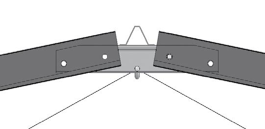
12 RAFER ASSEMBLY After setting the ground posts or anchoring the mounting feet, continue with the rafter assembly. Rafter Assembly NOE: All rafter assemblies consist of two rafter sections joined by a single splice at the peak. Consult the rafter diagram in the Quick Start section of these instructions before and during the rafter assembly process for details. CFG030PINSS01 Spice Assistance is required to assemble the rafters and frame. Gather the parts: Rafter sections (30' or 35' wide 2 sections per rafter) Rafter splice (# CFG030PINSS01) 3/8" x 2-1/2" bolts, nuts, and flat washers (to secure rafter sections to the splice) Place two rafter sections on the ground end-to-end. (he end of each section includes the two mounting holes to secure the splice.) Support the rafter sections with blocks as needed. Consult the diagrams for details. Connect the two rafter sections using a splice, 3/8" x 2-1/2" machine bolts, 3/8" flat washers, and 3/8" nuts. Position the installed studs of the splice so they point up to accept the top purlins when these are installed. See the diagram below. For long frames, it may be best to assemble the individual rafters and set them in place to conserve work space. o reduce handling, designate assembly areas along the length of the frame and set the individual rafter sections in those areas to be assembled and connected to the frame. 3. After assembling some or all of the rafters, continue with the frame assembly. SUPPOR BLOCKS Stud Splice 3/8" x 2 1/2" bolts (FAG361B), 3/8" flat washers (FAME08B), and 3/8" nuts (FALB04B) 12
 and 1/4\" nuts op purlins and hat channels (see Side Profile diagram for your building for purlin identification and correct position) and ek screws 108503 angle")

13 FRAME ASSEMBLY Gather the parts: Frame Assembly Assembled rafters and 1/2" x 2 1/2" mounting bolts, nuts, and flat washers Ridge purlins (see Side Profile diagram for your building and for purlin identification and correct position) and 1/4" nuts op purlins and hat channels (see Side Profile diagram for your building for purlin identification and correct position) and ek screws angle brackets to mount cables eyebolts, 3/8" lock washers, and 3/8" nuts Lifts, ladders, assistants, and cable, rope or lumber to secure rafters during the assembly process Complete these steps: 1. Using ladders and lifts, set an assembled rafter on the first set of ground posts, align the mounting holes, slide a flat washer onto a 1/2" x 2 1/2" bolt, and insert a bolt into each mounting hole. Position bolt head to the outside of the frame. AENION: If mounting feet are used, attach the first set of rafter legs to the mounted feet and secure with the 3/8" x 3 1/2" bolts and nuts. Consult the connection diagrams located in the Quick Start section of these instructions for additional details. 2. Slide one (1) angled bracket over each mounting bolt (end rafters only), add a 1/2" flat washer and nut to each bolt, and tighten. Bracket is to the inside of the frame and is used later in these instructions to secure the cable bracing to the frame. 3. Verify that the end rafter is vertical and not twisted and brace the rafter using ropes, cables, or lumber staked to the site. Do not remove the end rafter bracing until the entire frame is assembled. 3/8" x 3 1/2" Bolt 3/8" Nut Optional rafter leg with mounting foot. 1/2" x 2-1/2" Bolt Rope or Cable Ground Level 13

 and first interior rafter (B) using 1/4\" nuts. NOE: If a short purlin spans the first bay, do not secure the purlin to the second rafter until next purlin is added.")

14 Frame Assembly FRAME ASSEMBLY (continued) Move to the next set of ground posts (or mounting feet), attach that rafter (and rafter legs if needed), and brace in place. As previously described, use the 1/2" bolts to secure the rafter to the tops of the ground posts or rafter legs. ake the first section of ridge purlin (consult Side Profile diagram for your building length and correct purlin identification), align the pre-drilled holes with the studs of the rafter splice, and secure to the end rafter (A) and first interior rafter (B) using 1/4" nuts. NOE: If a short purlin spans the first bay, do not secure the purlin to the second rafter until next purlin is added. Consult the Side Profile diagram for your frame for details. Splice Studs Ridge Purlin Ridge Purlin 1/4" Nuts A B Example shows a long 12' purlin in the first bay position. Different frame lengths may have a shorter first purlin. A B NOE: he 20', 30', and 36' long frames use a combination of different purlin lengths during frame assembly. Consult the Side Profile diagram for your building length to determine which purlin to use and where to install that purlin. Some frame lengths use a 4' or 6' (short) purlin to span the first bay and to connect the first two rafters. Rope or Cable Ground Level 14


15 Frame Assembly FRAME ASSEMBLY (continued) Set the next rafter in place, secure it to the ground posts or rafter legs, and brace in place as needed. ake the next purlin and place the mounting holes over the splice studs and secure with the 1/4" nuts. ake one eyebolt, FAMA38B lock washer, and a 3/8" nut (FALB04B) and attach the eyebolt to the splice of the third (3rd) rafter as shown (C). Position the eye of the bolt toward the end rafter for the cable installation. DO NO secure this end of the ridge purlin to the rafter at this time. Ridge purlin is secured to the rafter in the following steps. Overlap ridge purlins and secure in place using 1/4" nuts. Ridge Purlin C eyebolt, FAMA38B lock washer, and FALB04 nut Diagram above shows how to connect the next purlin at the same splice. Use one set of 1/4" nuts to secure both purlins. C Rope or Cable Ground Level 15


16 Frame Assembly FRAME ASSEMBLY (continued) 9. With the first two bays (3 rafters) assembled, take the first top purlin and secure it to the rafters using ek screws. See Diagrams D and E at the right. ek screw Purlin NOE: he purlin pattern is the same as the ridge purlin. Consult the Side Profile diagrams for pattern details and purlin identification. Rafter Location of the purlins vary between styles of buildings. Refer to the Purlin Location diagrams in the Quick Start sections for the location for each purlin and the distance between each purlin. 10. Install and secure the remaining top purlins for the first bay as previously described and as shown in the Quick Start section of these instructions. D ek screw 11. Repeat the previous steps to assemble the remainder of the rafters. AENION: Attach the final eyebolt to the splice of the third (3rd) from the last rafter as described in Step 8. When setting the remaining end rafter, install the final two (2) angled cable brackets as described in Steps 1 and 2. Cable Bracket E Purlin Rafter Ridge Purlin Eyebolt Cable Bracket Purlin Eyebolt Purlin Cable Bracket D E Ground Level Cable Bracket Frame length of your building may differ from what is shown. 16
. 14.")

17 Frame Assembly FRAME ASSEMBLY (continued) 12. With the top purlins attached to the frame, measure 12" down from the corner of the end rafter and mark the location (see Diagram F). his mark identifies the bottom edge of the first run of hat channel. 13. Measure 12" up from the finished grade and mark the location (see Diagram G). 14. Move to the other end rafter and mark the same locations. 15. Stretch a chalk line from end-to-end and snap the line to mark the locations on each ground post/rafter leg. 16. ake the first section of hat channel, position near the top of the ground post/rafter leg, and secure it in place using FA4482B ek screws. NOE: Verify that the lower edge of the hat channel is on the chalk line created in previous steps. he hat channel pattern is the same as the top purlins. Consult the Side Profile diagrams for details and part identification. 17. Select another section of hat channel, overlap the first section by a few inches, align bolt holes, and secure the hat channel to the ground posts/rafter legs using FA4482B ek screws. 18. Continue adding and attaching sections of hat channel until the other end of the frame is reached and the run of hat channel is complete. REMEMBER: Sidewall hat channel runs and the top purlin runs are identical and use the same frame components and fasteners. F G 12" 12" Upper Hat Channel Lower Hat Channel Ground Level (finished grade) Ground Level F G Frame length of your building may differ from what is shown. 17
18 Frame Assembly FRAME ASSEMBLY (continued) 19. Move to the other side of the frame and repeat the steps needed to install the upper and lower runs of hat channel for that side. 20. With the first two runs of hat channel installed on each side of the frame, measure between the two runs of hat channel, mark the location as needed to center the final run of side hat channel. 21. Repeat the previous step for the remaining side of the frame. 22. Stretch and snap a chalk line to mark the lower edge of the center run of hat channel and install this run as previously described (see Diagram H). he hat channel pattern is the same as the top purlins. Consult the Side Profile diagrams for details. 23. Repeat the steps needed to install the center run of hat channel for the remaining side of the frame. H Center Hat Channel Ground Level Ground Level H Frame length of your building may differ from what is shown. 18
 5/16\" nuts ( supplied by customer) he following procedure describes one way to install the recommended baseboards.")
 5/16\" x 5\" carriage bolts and nuts.")
19 Recommended Baseboard Installation RECOMMENDED BASEBOARD INSALLAION Gather the parts: 2" x 6" or 2" x 4" treated or recycled plastic lumber (supplied by customer) 5/16" x 5" carriage bolts ( supplied by customer) 5/16" nuts ( supplied by customer) he following procedure describes one way to install the recommended baseboards. he size and type of the baseboard you choose may require the use of alternative steps. When properly installed, baseboard runs the length of the frame at ground level. he baseboard and fasteners are supplied by the customer. On the outside of the rafter leg/ground post, attach the first baseboard to the rafter using two (2) 5/16" x 5" carriage bolts and nuts. Continue adding baseboards to complete the first run. Splices are made between posts as shown in the drawing below. Use a short section of baseboard to secure separate baseboards at a splice. Repeat steps to install the second run of baseboards on the remaining side of the frame. NOE: he boards should be at ground level or slightly into grade to help prevent the shelter from shifting and to provide a seal at ground level. Ground Posts and Baseboard Baseboard Baseboard Ground Level Ground Level Rafter Feet and Baseboard Baseboards and fasteners are supplied by the customer. Hat Channel Inside of Shelter Splice 5/16" Nuts Ground Level Outside of Shelter 5/16" x 5" Carriage Bolts Ground Level 19
 length of cable: Measure from point-to-point on the frame and cut cable length as needed.")
20 Cable Installation CABLE ASSEMBLY Cable assemblies provide diagonal bracing for the building. Each cable assembly includes the following items: One (1) length of cable: Measure from point-to-point on the frame and cut cable length as needed. Remember to allow extra to secure the connections and install the clamps. urnbuckle (1) and anchor shackle (AS2167) (1) Cable thimbles (2) and cable clamps (4) Cable Assembly Procedure 1. Using the diagram below, measure between points A & B, add 12" for connections, and cut two lengths of cable from the supplied roll to the determined length. Dead End Cable Clamps himble urnbuckle Jaw himble urnbuckle Anchor Shackle Cable Clamp Cable urnbuckle Jaw himble End (Attach thimble end to the anchor shackle.) AENION: Always measure before cutting the cable. A B ypical urnbuckle Assembly 5. Attach turnbuckle jaw to the cable bracket at the end rafter connection. ake two turnbuckles and add a thimble to one end of each. Use adjustable pliers to snap the thimble over the jaw bolt or remove and reinstall the bolt to add the thimble. Cable Ground Level Measure between Points A & B, add extra for connections, and cut the cable to length. All cable sections will be the same length. Finish one cable end of each cable (Step 1) using a thimble and two (2) cable clamps. Use the diagrams as guides. Remove the bolt from the anchor shackle and slide the finished end of each rough cable onto the shackle. See the diagram at the upper-right corner of this page. Secure the anchor shackle to the eyebolt attached to the peak of the third rafter. See diagrams on the next page Open a turnbuckle (Step 5) to its extended/open position and secure the free end (one without the thimble) to the cable bracket attached to the end rafter ground post. (See diagrams on the next page.) Repeat for the remaining corner of the same end rafter. hread the free end of one cable (Step 4) around the thimble installed in Step 5, pull the cable tight to remove any slack, and secure the cable to the turnbuckle using two cable clamps. Repeat the previous step to attach the remaining turnbuckle to the free end of the remaining cable. Check all clamps and bolts of each cable assembly to ensure they are tight. rim or tape cable ends. 10. Repeat the above procedure to install the cables at the other end of the assembled frame. 11. With all cables assembled and attached, tighten each turnbuckle. Do not overtighten. 20


21 Cable Installation INSALL AND IGHEN ALL CABLES he diagram and inserts below identify the placement and proper way to attach the cable assemblies to the frame. After attaching all cables to the frame, tighten the turnbuckles. urnbuckles should be snug and not overtightened. Shorten cable if you are unable to tighten the turnbuckle to remove cable slack. himble Diagram shows the cables attached to the shackle and the shackle secured to the eyebolt. Shackle Cable Ground Level Frame length and design of your building may differ from what is shown. Secure the turnbuckle directly to the cable bracket attached to each end rafter mounting bolt. If necessary, use a bar or clamp to slightly bend the bracket to allow the needed clearance to install the jaw bolt of the turnbuckle. Actual turnbuckle may differ. 21

 strut; frame with a 4' rafter spacing use the")
, FAME07B flat washers, and FALF37B 5/16\" locknut ape measure, marker, hammer,")
 or a vice, bend each flattened end of the strut as shown in the diagram and photos to")

 between the end rafter and first interior rafter.")

22 Diagonal Strut Installation SRU INSALLAION For additional support, attach diagonal struts to the frame between the end rafter and the first interior rafter at each end. Collect the needed parts and install the diagonal struts as instructed below. Required parts and tools: Frame with 6' rafter spacing use the (8') strut; frame with a 4' rafter spacing use the QH1308 (7') strut. Secure using FAG340B (5/16" x 3 1/2" bolt), FAME07B flat washers, and FALF37B 5/16" locknut ape measure, marker, hammer, vise grip, center punch, and drill with 3/8" drill bit Diagonal Strut Complete these steps: 1. Using a vise grip (or similar tool) or a vice, bend each flattened end of the strut as shown in the diagram and photos to the right. When installed, ends are tight to the frame. AENION: Verify you have selected the correct strut. Some frames include struts of different lengths. Consult the diagrams in the Quick Start section for your building for additional details. 2. Position strut as shown (lower-right photo) between the end rafter and first interior rafter. (Adjust position so strut does not interfere with any other building component.) 3. Mark the mounting hole locations and drill holes using a 3/8" drill bit Insert a bolt with washer through the mounting holes and add another washer and locknut. ighten the nut to secure the strut to the frame. Continue by installing the remaining diagonal struts. Bend strut ends as shown. A Drill 3/8" hole. B Secure with 5/16" bolt, washers, and locknut. A & B Diagonal Strut C D C & D Ground Level Diagrams above show how to secure strut to the assembled frame. Diagram above shows strut position as seen from the inside of the frame. 22

 struts Secure using FAG330B (5/16\" x 1\" bolt), FAME07B flat washer, and FALF37B 5/16\" locknuts ape measure,")


23 Mounting Foot-to-Rafter Strut Installation MOUNING FOO-O-RAFER SRU INSALLAION Frames that include the mounting feet also include an additional strut running from the foot to the rafter. Complete the steps below to install the struts. NOE: If your building includes ground posts, skip this section and read ANCHOR HE ASSEMBLED FRAME information on the next page. Required parts and tools: (8') struts Secure using FAG330B (5/16" x 1" bolt), FAME07B flat washer, and FALF37B 5/16" locknuts ape measure, marker, hammer, center punch, and drill with 3/8" drill bit Foot-to-Rafter Strut Complete these steps: 1. ake a strut and loosely attach it to the rafter foot using the 5/16" fasteners listed above. 2. Swing the diagonal strut up into position until it reaches the underside of the rafter. 3. Mark the hole location and drill a mounting hole using the 3/8" drill bit. 4. Insert the bolt through the rafter hole and through the mounting hole in the diagonal strut. 5. Add a flat washer and locknut and tighten to secure the strut to the rafter. 6. Return to the lower 5/16" bolt and tighten that locknut. 7. Repeat to attach all remaining struts. SEP 1: Loosely secure strut to foot using 5/16" x 1" bolts, washers, and locknuts. SEP 4 & 5: Secure upper end of strut to rafter using the 5/16" x 1" bolt and related washer and nut. ighten upper and lower 5/16" nuts. SEP 2 & 3: Swing strut up and into position. Mark the hole location on the rafter, and drill using a 3/8" drill bit. 23
 end rafters for buildings with end walls, install these now. If these optional packages were not purchased, skip this section and continue with the frame assembly.")
24 Optional Support Package Installation (Rafter) INSALL RAFER SUPPOR PACKAGES: R030A0015 (30' WIDE) OR R035A0015 (35' WIDE) If you purchased the rafter support package (recommended) for each rafter, excluding the two (2) end rafters for buildings with end walls, install these now. If these optional packages were not purchased, skip this section and continue with the frame assembly. o purchase rafter support packages for your building, call your sales representative. Each support package contains: 1.66" pipe (166S099, 166S075, & 166P027 for 30' wide) or 1.90" pipe (190S099 and 190P058 for 35' wide) QH1304 (5' struts) and FA4482B ek Screws 3/8" x 2 1/2" bolts (FAG361B), 3/8" flat washers (FAMF04B), and 3/8" nuts (FALB04B) he following steps describe one way to assemble and attach the rafter support bracing. Consult the diagrams for your building for dimensions and component locations Using the diagrams for reference, take the 1.66" pipe (30' wide) or the 1.90" pipe (35' wide) and assemble the rafter chord as shown. Consult the Rafter Profile diagram for your support package in the Quick Start section (back). Measure approximately 1/2" in from each end of the assembled chord and drill a 3/8" mounting hole. With assistance, lift the chord up into position, verify that it is level, and mark and drill the mounting holes through the rafter. Secure the chord to the rafter using the 3/8" fasteners. AENION: If your building includes the installation of end wall framing, do not attach these support components to either end rafter. Doing so will interfere with the installation of the end wall frame. For buildings that have or will have end walls, begin with the first interior rafter. 4. Move to each pipe splice of the assembled chord and secure using one FA4482B ek screw. Secure using the 3/8" fasteners. Secure all chord pipe splices using FA4482B ek screws. Mounting Hole Drill mounting hole through assembled rafter. Secure each splice using an FA4482B ek screw. Assemble Chord Sample rafter is shown. Actual rafter may differ in design. Ground Level 24

25 Optional Support Package Installation (Rafter) SUPPOR PACKAGE INSALLAION (continued) Using the rafter as a guide, locate and mark the centerline of the chord. Use this line to install the vertical struts. Consult the diagram, mark the mounting hole locations for each strut and drill a 3/8" hole through the installed chord. AENION: Verify that the chord is level and not sagging. Before drilling the mounting hole, check that the QH1304 strut reaches the underside of the rafter. Adjust its position on the installed chord as needed. When installed correctly, the chord-to-rafter connection will form a 90 angle. See B in the diagram below. 7. Attach one strut to the installed chord using the 3/8" fasteners. Swing the free end up until it is plumb, drill a 3/8" mounting hole through the rafter, and secure the strut to the rafter using the 3/8" fasteners. Centerline B A A B QH1304 Strut Step 6 he on-center strut dimension differs for the 30' and 35' wide frames. Check the Rafter Profile diagram in the Quick Start section of this manual for your support kit for the correct on-center dimension. Ground Level Repeat to install the remaining strut. Verify that all mounting bolts are tight. 10. Repeat the steps to install the rafter bracing for all remaining rafters. Do not install on any end rafter where end wall framing will be installed. 11. Continue with the installation steps that follow. 25


26 Anchor the Assembled Frame ANCHOR HE ASSEMBLED FRAME At this point, anchor the assembled frame. Consult the MUS READ document for anchoring information and suggestions. Please call customer service at for additional anchoring information if needed. CAUION: he anchor assembly is an integral part of the frame construction. Improper anchoring may cause instability and failure of the structure to perform as designed. Failing to anchor the shelter properly will void the manufacturer s warranty and may cause serious injury and damage. If the optional anchor kit was purchased, use the diagrams below to properly install the auger-style earth anchor and to attach the brackets to the ground posts or rafter legs. AENION: Concrete must be used in loose or sandy soil types. For best results, install the auger-style earth anchor as close to the ground post or rafter leg as possible. After anchoring the frame, continue with the frame check. Ground Level urnbuckle 24" 24" Concrete Pier Concrete Concrete Minimum 3,000 psi AENION: All anchoring components shown require and additional purchase and are not included with the building kit. Ground Level Anchor AENION: Install the auger-style earth anchors to the inside of the shelter. 26
 Wafer head screws (#108553) Ladder (or lift) to reach peak of frame 1. 2. Measure and mark the center of the end rafter as shown in Diagram A.")

27 Ridge Cap Installation INSALL FIRS RUN OF RIDGE CAP Complete these steps to attach the first run of ridge cap. A second run of ridge cap is installed later in these instructions. Required parts and tools: Ridge cap sections (#108505) Wafer head screws (#108553) Ladder (or lift) to reach peak of frame Measure and mark the center of the end rafter as shown in Diagram A. ake a section of ridge cap (108505) and align the edge of the cap with the center line. he other end of the corner cap will extend past the first interior rafter. NOE: Have an assistant hold the cap in position. 3. Working from outside the frame, secure the ridge cap to the end rafter using wafer head screws. DO NO secure the free end of the corner cap until you overlap the cap with the next section (Step 4). op View End Rafter A B Ridge Cap Wafer Head Screws Center Line After installing the first section of ridge cap, select another section, overlap the first by 1", and secure the ridge cap to the interior rafter (see Diagram B). Repeat these steps until the installation of the ridge cap is complete. NOE: o install the last section of ridge cap, overlap the previous section as needed so that it aligns with the center of the end rafter. Ridge Cap A B Ground Level Wafer Head Screw Frame length of your building may differ from what is shown. 27


 overhang for corrugated cover. 3.")

28 End Cap Installation INSALL ALUMINUM END CAP Gather the parts: Aluminum end caps (# ' wide shelters or # ' wide shelters) Wafer screws (#108553) 1. Position end cap on top of the purlins. End Cap NOE: o finish the peak of the end rafter, mark and cut the upper end of each section so they meet to form a finished joint. rim the end caps as needed for a finished appearance and to close the gap. Consult a professional contractor if needed when cutting the aluminum. Wear safety glasses and hearing protection when handling and cutting end caps. 2. Move to the lower end and cut the end cap to length. Allow the end cap to overhang the end of the rafter section as shown in Fig. 1. Do not allow more than six inches (6") overhang for corrugated cover. 3. Align end cap with the end rafter as shown (Fig. 2) and secure to the purlin using two or three wafer-head screws (108553). 4. Install the remaining end cap for the first end rafter Return to both end caps and secure to each purlin using two or three screws. Repeat these steps to install the remaining end caps. End Cap Ridge Cap Wafer Screws End Cap Dashed lines show end rafter edge Wafer-Head Screw OP VIEW End Cap Ground Level Fig. 1 (Step 2) Wafer Screw End Cap 1-1/4" overhang 6" Purlin End Rafter Maximum 6" overhang; cut to length. Fig. 2 (Step 3) 28


 Foam closure strip (104709) ek screws (# FA4484B) Neo-bonded washers (#102921B) he")
 rib only.")
29 Install Corrugated Panels INSALL CORRUGAED PANELS: OVERVIEW If optional end frame or end panels have been ordered, install the end frame and end panels before attaching the sidewall panels of the main greenhouse. Consult the end frame and end panel instructions for details. After installing those components, return to these instructions and continue with the installation of the corrugated panels. Read the following before you install the panels: Do not install panels on a windy or stormy day. Use assistants and the proper lifts when setting the panels in place. Do not climb on the panels during installation or at any other time. Space ek screws and washers at 6" intervals to secure panels to the hat channel. Install all fasteners for the roof panels on the top rib of the corrugated panels. Install all fasteners for the side panels in the valleys of the corrugated panels. Insert a closure strip (104709) between the hat channel and panel before attaching the panel with screws and washers. Do not overtighten the panel mounting screws. Screws should be snug, but should not flatten the foam closure strips (104709) or distort the seal of the neo-bonded washer. Components needed: Corrugated panels and clear ridge cap (#106478) Foam closure strip (104709) ek screws (# FA4484B) Neo-bonded washers (#102921B) he corrugated roof panels are attached to the tops of each hat channel using ek screws and washers. hese panels are designed to span 48" on-center, which allows each panel to overlap the previous panel by one (1) rib only. CONSUL HE MAIN COVER DEAILS DIAGRAM IN HE QUICK SAR SECION OF HIS DOCUMEN FOR ROOF PANEL INSALLAION DEAILS. he diagram below shows the locations of the different panels. Frame shown below may differ from the actual frame. It is used to show panel locations. Fifteen (15) full panels are used between two (2) bays. Upper panels will overlap the top edge of the lower panels. Seam between panels Upper Panels: Use 50" x 12' 2" panels and either a 50" x 8' 2" or 50" x 12' 2" panel depending on the frame purchased. Ground Level Frame length of your building may differ from what is shown. Lower Side Panels: Use 50" x 12' 2" panels cut in half (all widths, all lengths) 29

 are used to secure all corrugated panels to the")


30 Install Corrugated Panels INSALL HE UPPER ROOF PANELS Complete the steps that follow to install the roof panels. AENION: ek screws (#FA4484) and neo-bonded washers (#102921) are used to secure all corrugated panels to the hat channels Choose one 12' 2" corrugated panel and position the panel on the hat channel and flush against the end cap channel. Verify that the lower end of the panel is aligned with the hat channel attached to the roof frame. NOE: Install a section of the horizontal closure strip under the edge of the panel (see Diagram A) and before attaching the panel to the hat channels. Secure the first panel to the first two (2) runs of hat channels on top of the ribs using ek screws and washers (see photo B). A B End Cap Closure Strip Panel DO NO SECURE HE UPPER END OF HE UPPER PANEL O HE OP OF HE RIDGE CAP UNIL HE CORRUGAED RIDGE CAP IS IN POSIION. 3. Install ek screws and washers through the panel, closure strip, and into the hat channel every 6" or so. Always install ek screws and washers on the top of the ribs for the roof panels. Do not overtighten screws. DO NO SECURE HE INSIDE RIB WHERE HE NEX PANEL OVERLAPS UNIL HE NEX PANEL IS IN POSIION. Closure Strip ek screw and washer ALLOW HE LOWER EDGE OF HE UPPER PANEL O REMAIN FREE SO I CAN BE LIFED O INSALL HE LOWER PANEL. A B Install a closure strip under each panel at each hat channel. Do not overtighten the mounting screws. If washer seal becomes deformed, washer is too tight. Ground Level Frame length of your building may differ from what is shown. 30
 4.")


 Installed end cap is not shown.")


31 Install Corrugated Panels INSALL HE UPPER ROOF PANELS (continued) 4. Choose another 12' 2" panel and move to the other side of the frame between the same rafters. Attach the panel as previously described. Use a section of corrugated ridge cap as a guide to align the panels AENION: Do not run ek screws into the last/ inside rib of the panel at this time. he next panel will overlap the previous panel, which is the repeated pattern throughout the length of the frame. DO NO SECURE HE UPPER END OF HE UPPER PANEL O HE LOWER RIDGE CAP UNIL HE CORRUGAED RIDGE CAP IS IN POSIION. ake a section of corrugated ridge cap and place it between the tops of the two adjacent panels. Using ek screws and neo-bonded washers, secure the corrugated ridge cap section by driving the ek screws through the ridge cap, roof panel, foam closure strip, and into the lower ridge cap (see photo below). Use the same spacing as the screws used to secure the roof panels in place on the frame. Lower Ridge Cap ek screw and washer Roof Panel Foam Closure Strip (104709) Installed end cap is not shown. Corrugated Ridge Cap Roof Panel End Rafter NOE: Verify that the horizontal closure strip under the edge of each panel is in place before attaching the ridge cap to the frame. NOE: o this point, the first run of roof panels (2 panels and a section of corrugated ridge cap) should be in place and secured to the hat channels. No fasteners are installed along the inside edge of any panel. he next set of panels overlaps this edge before screws and washers are installed. Dashed line (below) identifies the position of the foam closure strip (104709). ek screw and washer Ground Level 31
 rib and must be square on the hat channel.")
 between the panel and the hat channels and continue as previously described. Install the strip from inside the greenhouse for easier access.")
32 Install Corrugated Panels INSALL HE UPPER ROOF PANELS (continued) 7. Once the first run of roof panels is secured, install the next run of roof panels. 8. AENION: his panel will overlap the inside edge of the installed panels by one (1) rib and must be square on the hat channel. Verify that the lower end of the panel is aligned with the hat channel at that position. Install the horizontal closure strip (104709) between the panel and the hat channels and continue as previously described. Install the strip from inside the greenhouse for easier access. Continue installing the corrugated polycarbonate roof panels and securing the overlap seams until all roof panels are installed. Overlap adjacent panel and slide under the lip of the corrugated ridge cap. NOE: If the final roof panel is too wide and extends beyond the end rafter, trim the panel to the correct width or overlap the previous panel as needed. Rib Corrugated Panel 9. With the roof panels attached, continue with the installation of the lower roof panels. Corrugated Panel Overlap panels by one (1) rib as shown above. Installed Ridge Cap Ground Level Frame length of your building may differ from what is shown. 32


 AENION:")


. 2.")
")


33 Install Corrugated Panels INSALL HE LOWER ROOF PANELS Gather the parts: Corrugated panels (50" x 8' 2" - 30' wide shelters or 50" x 12' 2" - 35' wide shelters) ek screws (# FA4484B) Neo-bonded washers (#102921) AENION: Verify you have selected the correct panels when installing the lower roof. Some frames include panels of different sizes. Consult the diagrams in the Quick Start section of your building for additional details. 1. Lift the lower edge of the upper panel and slide the lower panel between the upper panel and hat channel of the roof frame. AENION: When properly positioned, the upper panel overlaps the top edge of the lower panel (minimum: 6"). 2. From inside the greenhouse, install the horizontal closure strip (104709) between the lower panel and the remaining hat channels as shown in the photo above Position the panel square on the hat channel and flush against the end cap. Verify that the lower end of the panel is aligned with the frame and the end of the end cap. Secure the lower panel to three (3) runs of hat channel using ek screws and washers installed through the panel, closure strip, and into the hat channel as previously described in the upper panel installation. With the lower panel attached to the rafter, repeat the steps to install the remaining lower panels. AENION: Each panel overlaps the edge of the installed panels and must be square on the hat channel and frame Beginning at the end rafter on the other side of the frame, install the remaining lower roof panels using the previous steps as a guide. Verify that all panel overlap seams are secured with ek screws and washers installed through the two panels, closure strip, and into the hat channel. Minimum overlap is 6". Continue with the installation of the side panels. Closure Strip ek screw and washer Maximum overhang is 6". 33

 rib. INSALL CORRUGAED SIDE PANELS Install panel ribs vertically to allow condensation to properly drain.")
34 Install Corrugated Panels CORRUGAED SIDE PANEL INSALLAION he instructions below describe how to install the corrugated side panels of the greenhouse. Consult the following information before you begin to install the corrugated panels for the sides. Side Panel (one panel): Use a 50" x 6' 1" panel (maximum length) cut from a 50" x 12' 2" corrugated panel. Secure panels to the hat channel using FA4484 ek screws and neo-bonded washers (102921). When installed properly, the panels overlap each other by one (1) rib. INSALL CORRUGAED SIDE PANELS Install panel ribs vertically to allow condensation to properly drain. Complete these steps to install the corrugated side panels: ake a 50" x 12' 2" panel and cut it in half to create two (2) 50" x 6' 1" panels. NOE: Measure sidewall height and cut panels to fit: Maximum panel length is 6' 1". ake one pre-cut panel and place the side panel against the hat channels attached along the frame and slide the panel up until it meets the underside of the roof panel. If end panels are present, shift the sidewall panel as needed to meet end wall panel and to close the corner joint between the end wall and sidewall. NOE: If a baseboard has been installed, set the panel an inch or so above ground level to protect the lower edge of the panel. Hat Channel Side Panels Frame length of your building may differ from what is shown. AENION: Side wall height may vary depending on the site, ground post installation, or how mounting feet were set on the site. When cutting the side panels, do not cut panels greater than 6' 1". Doing so will result in a shortage of panels. All side panels are cut from full 12' 2" corrugated panels. 3. Install customer-supplied wood screws and washers to secure the lower edge of the panel to the baseboard. After squaring the panel on the frame, attach the panel to the hat channel in the valleys using FA4484B ek screws and neo-bonded washers (102921B). Space screws and washers at 6" intervals or so. Overlap No fastener in this valley. Valley for fastener. Overlap panels by one (1) rib as shown above. DO NO run ek screws into the last valley of the panel at this time. he next panel will overlap the previous panel, which is the repeated pattern throughout the length of the frame. 34
.")
 rib and must be square with the frame.")
 or overlap the required ribs and install using the previous steps as a guide.")
35 Install Corrugated Panels INSALL CORRUGAED SIDE PANELS (continued) 4. Once the first side panel is secured, install the next side panel using ek screws and neo-bonded washers (see photo A). Installed Roof Panel Slide side panel up to meet roof panel AENION: his panel overlaps the edge of the installed panels by one (1) rib and must be square with the frame. Continue installing panels until the both sides of the frame are covered. NOE: rim the last panel to the proper width (if needed) or overlap the required ribs and install using the previous steps as a guide. If baseboards are installed, return to each panel and install customer-supplied wood screws and washers as shown in the photo B. Continue by applying the silicone (optional and supplied by the customer). Maximum overhang is 6" for corrugated roof panels. 50" x 6' 1" Corrugated Side Panel (maximum height) Customer-Supplied Baseboard Ground Level A Ground Level B 35

36 Install Corrugated Panels APPLY SEALAN (optional step) In addition to the installation the individual corrugated panels, applying sealant at different joints and seams throughout the greenhouse can help seal the structure. he application of sealant is left to the discretion of the owner or contractor and is typically completed when a tighter seal between components is desired. Sealant is supplied by the customer. It is not included with your building kit. Space below is reserved for customer notes. hough a complete air and water-tight seal may not possible, taking the following steps may help maintain a more stable interior environment. NOE: he amount of sealant used to seal the greenhouse varies with the size of the applied bead. Purchase sealant locally or by calling your sales representative. 1. Inspect the assembled greenhouse and apply sealant in those areas where additional sealing is desired Seal all holes created during the assembly of the greenhouse. Continue by reading the care and maintenance information. 36
37 Shelter Care and Maintenance SHELER CARE AND MAINENANCE Proper care and maintenance of the shelter is important. Check the following items periodically to properly maintain the shelter: Regularly check the corrugated panels to see that these are secure and in good condition. Replace or repair damaged panels if needed. Check connections and all fasteners to verify that they remain tight. Repair or replace all damaged components immediately. Do not climb or stand on the greenhouse at anytime. (See the ridge cap installation notes.) Inspect the anchoring system to verify that all components remain tight and in good condition. Repair or replace as needed. Remove debris and objects that can accumulate on the greenhouse. Use tools that will not damage the cover when removing debris. Remove snow to prevent excess accumulation. Use tools that will not damage the corrugated panels when removing snow. Check the contents of the shelter to verify that nothing is touching the corrugated panels that could cause damage. If the greenhouse is disassembled and moved, inspect all parts and connections before it is reassembled. Depending on the contents, construction of the shelter, shelter materials, and shelter location, the potential for condensation exists. ClearSpan offers several items that can be used to alleviate a condensation condition. Please contact a ClearSpan representative for additional information. For replacement or missing parts, call for assistance. Space below is reserved for customer notes. NOE: With the exception of russ Arch buildings or as otherwise noted, ClearSpan shelters and greenhouses do not have any tested loading criteria. 37

38 Quick Start Guide QUICK SAR GUIDE 30' and 35' Wide Greenhouses AENION: Shelter to the right shows mounting feet and an installed anchor system. Actual building may differ in length or design or both. Ground Level Building is shown with customer-supplied baseboards. Frame includes ground posts. Frame length and width of your building may differ from what is shown. 38
ClearSpan Pro Solar Star Greenhouses
 ClearSpan Pro Solar Star Greenhouses Double-Layer Greenhouse Film Photo may show a building of a different length. Frame is shown with a roll-up side option and customer-supplied baseboards. End wall is
ClearSpan Mini Grab Bag Shelters
 ClearSpan Mini Grab Bag Shelters Photo may show a different but similar model. Baseboard is not included. 2008 ClearSpan All Rights Reserved. Reproduction is prohibited without permission. STK# DIMENSIONS
ClearSpan Mini Cold Frames
 ClearSpan Mini Cold Frames Photo may show a different but similar model. 2009 ClearSpan All Rights Reserved. Reproduction is prohibited without permission. STK# DIMENSIONS 105152 6' W x 5' H x 6' L 105153
Moo-Tel Small Animal Hut
 Moo-Tel Small Animal Hut Photo may show a different but similar model. 2010 ClearSpan All Rights Reserved. Reproduction is prohibited without permission. STK# DIMENSIONS 104602 4 6" W x 4' 10" H x 8 2"
ClearSpan Attached-Style Awning
 ClearSpan Attached-Style Awning Photo may show a different but similar model. 2007 ClearSpan All Rights Reserved. Reproduction is prohibited without permission. Revision date: July 2007ldg STK# DIMENSIONS
ClearSpan Mini Grab Bag Shelters
 ClearSpan Mini Grab Bag Shelters Photo may show a different but similar model. Baseboard is not included. 2008 ClearSpan All Rights Reserved. Reproduction is prohibited without permission. STK# DIMENSIONS
ClearSpan Pro Solar Star High Tunnels
 ClearSpan Pro Solar Star High Tunnels Photo may show a building of a different length. Frame is shown with a roll-up side option and customer-supplied baseboards. End wall is not included and requires
ClearSpan Grab Bag Canopy
 ClearSpan Grab Bag Canopy Photo may show a different but similar model. 2008 ClearSpan All Rights Reserved. Reproduction is prohibited without permission. STK# DIMENSIONS 104385 10 W x 20 L 1 YOU MUST
ClearSpan Pro Solar Star High Tunnels
 ClearSpan Pro Solar Star High Tunnels Photo may show a building of a different length. Frame is shown with a roll-up side option and customer-supplied baseboards. End wall is not included and requires
ClearSpan End Frame Kit 26' Wide x 12' High
 ClearSpan End Frame Kit 26' Wide x 12' High Diagram shows the end frame kit for an end wall without a door. (Door and end panel are purchased separately.) Rafter and struts shown in the above diagram are
GrowSpan Round Cold Frames
 GrowSpan Round Cold Frames Photo may show a different but similar model. 2016 Growers Supply All Rights Reserved. Reproduction is prohibited without permission. STK# DIMENSIONS 103099 12' W x 8' H x 24'
WeatherShield Covered Walkway and Connect-A-Building
 WeatherShield Covered Walkway and Connect-A-Building Photo may show a different but similar model. 2014 ClearSpan All Rights Reserved. Reproduction is prohibited without permission. STK# DIMENSIONS 104303
WeatherShield Daddy Long Legs Canopy
 WeatherShield Daddy Long Legs Canopy Photo may show a different but similar model. 2010 ClearSpan All Rights Reserved. Reproduction is prohibited without permission. Revision date: 06.210 STK# 1220RV10W10
ClearSpan End Frame Kit 30' Wide x 11' High
 ClearSpan End Frame Kit 30' Wide x 11' High Diagram shows the end frame kit for an end wall without a door. (Door and end panel are purchased separately.) Rafter and mounting feet shown in the above diagram
ClearSpan Majestic Greenhouse Film Roof with Roll-up Sides
 ClearSpan Majestic Greenhouse Film Roof with Roll-up Sides 28' Wide Photo may show a different but similar model. 2009 ClearSpan All Rights Reserved. Reproduction is prohibited without permission. STK#
ClearSpan PolyMax Windbreak Wall
 ClearSpan PolyMax Windbreak Wall Photo may show a different but similar model. 2007 ClearSpan All Rights Reserved. Reproduction is prohibited without permission. Revision date: February 2007ldg STK# DIMENSIONS
GrowSpan Series 500 Door Kits
 GrowSpan Series 500 Door Kits Double Swinging Door Finished Grade Finished Grade Diagram shows a double-swinging door centered and installed in an end wall frame. The door kit includes materials for the
ClearSpan Majestic Greenhouse Film Roof with Roll-up Sides
 ClearSpan Majestic Greenhouse Film Roof with Roll-up Sides 56' Wide Photo may show a different but similar model. 2009 ClearSpan All Rights Reserved. Reproduction is prohibited without permission. STK#
GrowSpan Gothic Cold Frames
 GrowSpan Gothic Cold Frames Photo may show a different but similar model. 2016 Growers Supply All Rights Reserved. Reproduction is prohibited without permission. STK# DIMENSIONS 106342 30' W x 12' H x
ClearSpan Twin-Wall Polycarbonate End Panel Kit
 ClearSpan Twin-Wall Polycarbonate End Kit 30' Wide & 35' Wide Diagram shows a sample end panel kit for a frame. Actual panel positions and sizes for your end panel package may differ from what is shown.
Moo-Tel Calf Hutch CLEARSPAN ANIMAL HOUSING W x 12 L W x 18 L W x 24 L
 Moo-Tel Calf Hutch Photo may show a different but similar model. 2008 ClearSpan All Rights Reserved. Reproduction is prohibited without permission. STK# DIMENSIONS 102852 14 W x 12 L 102853 14 W x 18 L
ClearSpan 38' Wide Aircraft Hangar
 ClearSpan 38' Wide Aircraft Hangar Photo may show a model of a different length. 2008 ClearSpan All Rights Reserved. Reproduction is prohibited without permission. STK# DIMENSIONS 107556 38' W x 15' H
ClearSpan 20' Wide Free-Standing Building
 ClearSpan 20' Wide Free-Standing Building Photo may show a different but similar model. 2018 ClearSpan All Rights Reserved. Reproduction is prohibited without permission. STK# PB00580R3/R4 PB00582R3/R4
ClearSpan Economy Round Style High Tunnel
 ClearSpan Economy Round Style High Tunnel Photo may show a different but similar model. 2012 ClearSpan All Rights Reserved. Reproduction is prohibited without permission. Revision date: 0112 STK# PB01725R6
ClearSpan PolyMax Windbreak Wall
 ClearSpan PolyMax Windbreak Wall Photo may show a different but similar model. 2007 ClearSpan All Rights Reserved. Reproduction is prohibited without permission. Revision date: April 2007ldg STK# DIMENSIONS
ClearSpan Round Style Mini Garage
 ClearSpan Round Style Mini Garage Photo may show a different but similar model. 2008 ClearSpan All Rights Reserved. Reproduction is prohibited without permission. STK# PB01900R4 DIMENSIONS 8' W x 8' H
ClearSpan 34' Wide Aircraft Hangar
 ClearSpan 34' Wide Aircraft Hangar Photo may show a model of a different length. 2012 ClearSpan All Rights Reserved. Reproduction is prohibited without permission. STK# DIMENSIONS 107554 34' W x 17' 4"
ClearSpan Majestic Greenhouse Film Roof with Polycarbonate Sides
 ClearSpan Majestic Greenhouse Film Roof with Polycarbonate Sides 84' Wide Photo may show a different but similar model. 2016 ClearSpan All Rights Reserved. Reproduction is prohibited without permission.
ClearSpan Corrugated Polycarbonate End Panel Kit
 ClearSpan Corrugated Polycarbonate End Kit 30' Wide & 35' Wide Frame size and layout shown above may differ from actual frame. Photo is used for illustration only. 2010 ClearSpan All Rights Reserved. Reproduction
ClearSpan Open Garages
 ClearSpan Open Garages Photo may show a different but similar model. 2007 ClearSpan All Rights Reserved. Reproduction is prohibited without permission. STK# PB02910R4 DIMENSIONS 18' W x 16' H x 52' L YOU
Premium Solar Star Greenhouse
 Premium Solar Star Greenhouse Assembly Instructions SKU# 104901 2006 ClearSpan All rights reserved. Reproduction without permission is prohibited. Revision date: March 2006g Contact your sales representative
Sliding Door Kit
 YOU MUST READ THIS DOCUMENT BEFORE YOU BEGIN TO ASSEMBLE THE DOOR KIT. Thank you for purchasing this GrowSpan door kit. When properly assembled and maintained, this product will provide years of reliable
GrowSpan Round Premium Corrugated Greenhouses
 GrowSpan Round Premium Corrugated Greenhouses Photo may show a different but similar model. 2018 Growers Supply All Rights Reserved. Reproduction is prohibited without permission. STK# DIMENSIONS 104933
Assembly Guide for Series 500 Ridge Vent Kits
 Assembly Guide for Series 500 Ridge Vent Kits Photo shows a sample ridge vent as installed on a greenhouse. Actual building and ridge vent length may differ. 2014 ClearSpan All Rights Reserved. Reproduction
Sliding Door Kit
 YOU MUST READ THIS DOCUMENT BEFORE YOU BEGIN TO ASSEMBLE THE DOOR KIT. Thank you for purchasing this GrowSpan door kit. When properly assembled and maintained, this product will provide years of reliable
GrowSpan Single Swinging Door Black-Out Door Kit
 GrowSpan Single Swinging Door Black-Out Door Kit ATTENTION: Door kit includes materials for door only. All other components shown in the diagram above and diagrams throughout this guide are not included
ClearSpan SolarGuard Round Style Storage Building
 ClearSpan SolarGuard Round Style Storage Building Photo may show a different but similar model. 2009 ClearSpan All Rights Reserved. Reproduction is prohibited without permission. Revision date: 131.09
Twin-Wall Double Swinging Door Kit
 115021 Twin-Wall Double Swinging Kit READ THIS DOCUMENT BEFORE YOU BEGIN Thank you for purchasing this GrowSpan door kit. When properly assembled and maintained, this product will provide years of reliable
GrowSpan Series 500 Roll-Up Ends
 GrowSpan Series 500 Roll-Up Ends Photo may show a different but similar model. Doorframe materials are not included. 2016 Growers Supply All Rights Reserved. Reproduction is prohibited without permission.
GrowSpan Round Premium High Tunnels
 GrowSpan Round Premium High Tunnels Photo may show a different but similar model. 2016 Growers Supply All Rights Reserved. Reproduction is prohibited without permission. STK# PB01680R4 PB01690R4 DIMENSIONS
GrowSpan Estate Pro I Greenhouse
 GrowSpan Estate Pro I Greenhouse Photo may show a different but similar model. 2016 Growers Supply All Rights Reserved. Reproduction is prohibited without permission. STK# DIMENSIONS 104564 11'-8" W x
GrowSpan Gothic Premium Greenhouses
 GrowSpan Gothic Premium Greenhouses Photo may show a different but similar model. 2016 Growers Supply All Rights Reserved. Reproduction is prohibited without permission. STK# DIMENSIONS 106209 16' W x
GrowSpan 24' Wide Series 500 Tall High Tunnels with Roll-Up Sides
 GrowSpan 24' Wide Series 500 Tall High Tunnels with Roll-Up Sides Photo may show a building of a different length and style. Frame shown includes roll-up sides and customer-supplied baseboards. Actual
GrowSpan Heavy-Duty Commercial Cold Frame
 GrowSpan Heavy-Duty Commercial Cold Frame Photo may show a different but similar model. 2018 Growers Supply All Rights Reserved. Reproduction is prohibited without permission. STK# DIMENSIONS 106363 4'
GrowSpan 30' Wide Series 500 Tall Greenhouses
 GrowSpan 30' Wide Series 500 Tall Greenhouses Photo may show a building of a different length and style. Frame shown includes optional roll-up sides and customer-supplied baseboards. Building shown is
GrowSpan 42' Wide Series 500 Tall High Tunnels with Roll-Up Sides
 GrowSpan 42' Wide Series 500 Tall High Tunnels with Roll-Up Sides Photo may show a building of a different length and style. Frame shown includes drop-down sides and customersupplied baseboards. Actual
ClearSpan Cedar 12' Wide End Frame Kit with Dutch Door
 ClearSpan Cedar 12' Wide End Frame Kit with Dutch Door Photo may show a different but similar model. 2010 ClearSpan All Rights Reserved. Reproduction is prohibited without permission. STK # WIDTH 105366
Elite Home-Attached Greenhouse
 Elite Home-Attached Greenhouse Photo may show a greenhouse of a different length. Elite Home-Attached Greenhouse Use these instructions for the following greenhouses: #104711 #104713 #104715 2007 ClearSpan
GrowSpan Series 2000 End Wall Cladding Kits
 GrowSpan Series 2000 End Wall Cladding Kits 35' Wide 2017 FarmTek All Rights Reserved. Reproduction is prohibited without permission. STK# 35' Wide (Twin Wall) Important Information READ THIS DOCUMENT
GrowSpan Series 2000 End Wall Cladding Kits
 GrowSpan Series 2000 End Wall Cladding Kits 20' Wide 2017 FarmTek All Rights Reserved. Reproduction is prohibited without permission. STK# 20' Wide (Twin Wall) Important Information READ THIS DOCUMENT
WHITE - Accessories. Series 500 Greenhouse Kit w/blackout System, Ventilation & Evaporative Cooling
 Series 500 Greenhouse Kit w/blackout System, Ventilation & Evaporative Cooling WHITE - Accessories 2016 Growers Supply All Rights Reserved. Reproduction is prohibited without permission. Revision date:
GrowSpan Series 1000 End Wall Cladding Kits
 GrowSpan Series 1000 End Wall Cladding Kits 24' Wide 2017 FarmTek All Rights Reserved. Reproduction is prohibited without permission. Revision date: 02.16.17 STK# GK1EWC24120G 24' Wide (Twin Wall) Important
GrowSpan Series 500 Automated Ridge Vent Kits
 GrowSpan Series 500 Automated Ridge Vent Kits Photo shows a sample ridge vent as installed on a greenhouse. Actual building and ridge vent length may differ. 2017 Growers Supply All Rights Reserved. Reproduction
GrowSpan Round Pro Greenhouses and Systems
 GrowSpan Round Pro Greenhouses and Systems Photo may show a different but similar model. 2018 Growers Supply All Rights Reserved. Reproduction is prohibited without permission. STK# DIMENSIONS 104836 14
GrowSpan Series 1000 End Wall Cladding Kits
 GrowSpan Series 1000 End Wall Cladding Kits 30' Wide 2017 FarmTek All Rights Reserved. Reproduction is prohibited without permission. Revision date: 02.16.17 STK# GK1EWC30120G 30' Wide (Twin Wall) Important
GrowSpan Gothic Pro Greenhouses and Systems
 GrowSpan Gothic Pro Greenhouses and Systems Photo may show a different but similar model. Film Cover with Film Roll-Up Side Panels 2016 Growers Supply All Rights Reserved. Reproduction is prohibited without
GrowSpan Gothic Pro Greenhouses and Systems
 GrowSpan Gothic Pro Greenhouses and Systems Photo may show a different but similar model. Full Polycarbonate Roof Cover and Ends 2016 Growers Supply All Rights Reserved. Reproduction is prohibited without
GrowSpan Round Pro Greenhouses and Systems
 GrowSpan Round Pro Greenhouses and Systems Photo may show a different but similar model. 2018 Growers Supply All Rights Reserved. Reproduction is prohibited without permission. STK# DIMENSIONS 104857 26'
ClearSpan Front Roll-Up Kit Installation Guide
 ClearSpan Front Roll-Up Kit Installation Guide Roll-up panel opened. Roll-up panel closed. Actual building and panel may differ from what is shown. 2008 ClearSpan All Rights Reserved. Reproduction is prohibited
ClearSpan Hydroponic Table Kit
 ClearSpan Hydroponic Table Kit Hydroponic Table Kit (The 109314 (4' x 16') model is shown.) Designed to grow healthy plants without soil using mineral-nutrient solutions. 2009 ClearSpan All Rights Reserved.
Twin-Wall Double Swinging Door Kit
 105105 Twin-Wall Double Swinging Kit YOU MUST READ THIS DOCUMENT BEFORE YOU BEGIN TO ASSEMBLE THE DOOR KIT. Thank you for purchasing this GrowSpan door kit. When properly assembled and maintained, this
GrowSpan Gothic Pro Greenhouses and Systems
 GrowSpan Gothic Pro Greenhouses and Systems Photo may show a different but similar model. 2017 Growers Supply All Rights Reserved. Reproduction is prohibited without permission. STK# DIMENSIONS 106306
PASSIVE SOLAR-HEATED GREENHOUSE
 PASSIVE SOLAR-HEATED GREENHOUSE Actual greenhouse length may differ from what is shown. SOLAR-HEATED GREENHOUSE Use these instructions for the following greenhouse skus: 106372 (Length: 20') 106373 (Length:
GrowSpan Gothic Pro Greenhouses and Systems
 GrowSpan Gothic Pro Greenhouses and Systems Photo may show a different but similar model. 2016 Growers Supply All Rights Reserved. Reproduction is prohibited without permission. STK# DIMENSIONS 106314
ClearSpan Super Moo-Tel Building 26' Wide
 ClearSpan Super Moo-Tel Building 26' Wide Photo may show a different but similar model. 2012 ClearSpan All Rights Reserved. Reproduction is prohibited without permission. STK# PB01500R3/R4 PB01510R3/R4
6' Wide Premium Greenhouse Benches
 6' Wide Premium Greenhouse Benches Premium Greenhouse Bench with Stationary Top 2015 FarmTek All Rights Reserved. Reproduction is prohibited without permission. STK# DIMENSIONS 112416S6X08 6' W x 3' H
ClearView Panels Mil 3 Finished Sides with Grommets 1 Hem Side Mil 3 Finished Sides with Grommets 1 Hem Side DESCRIPTION
 ClearView Panels Photo may show a different but similar model. 2006 FarmTek All Rights Reserved. Reproduction is prohibited without permission. Revision date: November 2006rp STK# DESCRIPTION 105659 16
6' Wide Premium Greenhouse Benches
 6' Wide Premium Greenhouse Benches Premium Greenhouse Bench with Rolling Top 2015 FarmTek All Rights Reserved. Reproduction is prohibited without permission. STK# DIMENSIONS 112416R6X08 6' W x 3' H x 8'
ClearSpan 36' Wide Pony Wall Building
 ClearSpan 36' Wide Pony Wall Building Ground Level Photo may show a model of a different length. Cover is not shown. 2017 ClearSpan All Rights Reserved. Reproduction is prohibited without permission. STK#
Breathable Wall Light Traps & Blackout Fan & Shutter Kits
 Breathable Wall Light Traps & Blackout Fan & Shutter Kits 2017 Growers Supply All Rights Reserved. Reproduction is prohibited without permission. Maintain controlled airflow without sacrificing blackout
GrowSpan Gothic HobbyPro Greenhouses
 GrowSpan Gothic HobbyPro Greenhouses Photo may show a different but similar model. 2016 Growers Supply All Rights Reserved. Reproduction is prohibited without permission. STK# DIMENSIONS 104889 16 W x
Double Truss Shelter Model# SST W9.14xL14.2xH4.88m Assembly Instructions
 Double Truss Shelter Model# SST304716 W9.14xL14.2xH4.88m Assembly Instructions Page 1 RECOMMENDED TOOLS Equipment List Speed Wrench 22#.23#.24# Hammer (30lb) Rope (12#) Long Tape (50m) Hammer Drill*1 Lifter*2
RED - Main Frame. Series 500 Greenhouse Kit w/blackout System, Ventilation & Evaporative Cooling
 Series 500 Greenhouse Kit w/blackout System, Ventilation & Evaporative Cooling RED - Main Frame 2017 Growers Supply All Rights Reserved. Reproduction is prohibited without permission. Revision date: 03.08.17
Blackout Fan Kits with Breathable Wall Light Traps
 Blackout Fan Kits with Breathable Wall Light Traps 2018 Growers Supply All Rights Reserved. Reproduction is prohibited without permission. Maintain controlled airflow without sacrificing blackout environments.
Anchor Kit Installation Guide
 Anchor Kit 105587 Installation Guide Use the following photos as guides to identify the rafter leg pipe diameter of your ClearSpan shelter. Install the anchor kit brackets as shown in the photos below.
GrowSpan Gothic Premium High Tunnels (All H Models)
") GrowSpan Gothic Premium High Tunnels (All H Models) Ground Level Photo may show a different but similar model. These instructions include information for buildings equipped with either drop-down side curtains
GrowSpan Gothic Premium High Tunnels (All H Models) Ground Level Photo may show a different but similar model. These instructions include information for buildings equipped with either drop-down side curtains
Blackout Fan Kits with Breathable Wall Light Traps
 Blackout Fan Kits with Breathable Wall Light Traps 2018 Growers Supply All Rights Reserved. Reproduction is prohibited without permission. Maintain controlled airflow without sacrificing blackout environments.
Blackout Fan Kit with Breathable Wall Light Trap
 Blackout Fan Kit with Breathable Wall Light Trap 2018 Growers Supply All Rights Reserved. Reproduction is prohibited without permission. Maintain controlled airflow without sacrificing blackout environments.
Moo-Tel Calf Nurseries
 MOO-TEL CALF NUSEIES Moo-Tel Calf Nurseries Photo may show a different but similar model. 2008 ClearSpan All ights eserved. eproduction is prohibited without permission. evision date: 10.13.08 STK# DIMENSIONS
GREEN - Main Frame Film Cladding
 Series 500 Greenhouse Kit w/blackout System GREEN - Main Frame Film Cladding 2017 Growers Supply All Rights Reserved. Reproduction is prohibited without permission. GB30_GREEN 30' Wide Series 500 Main
ClearSpan Twist-of-the-Wrist Assembly Instructions
 ClearSpan Twist-of-the-Wrist Assembly Instructions Curved-Wall for Roll-Up Side Flat-Wall for Curtain Application 2008 ClearSpan All Rights Reserved. Reproduction is prohibited without permission. Revision
Insect Screen for Exhaust Fans
 Insect Screen for Exhaust Fans Actual fan and screen kit may differ. 2016 Growers Supply All Rights Reserved. Reproduction is prohibited without permission. STK# 115106F 115107F 115108F DIMENSIONS 24"
ClearSpan Raised Bed Kits
 ClearSpan Raised Bed Kits Photo may show a different but similar model. 2010 ClearSpan All Rights Reserved. Reproduction is prohibited without permission. STK# DIMENSIONS TIERS 106457 4' W x 8' L 1 106458
ClearSpan 30' Wide Econoline Storage Building
 CLEASPAN POLY BUILDINGS ClearSpan 30' Wide Econoline Storage Building Photo may show a model of a different length. 2008 ClearSpan All ights eserved. eproduction is prohibited without permission. evision
ClearSpan 30' Wide Pony Wall Building
 CLEASPAN POLY BUILDINGS ClearSpan 30' Wide Pony Wall Building Photo may show a model of a different length. 2015 ClearSpan All ights eserved. eproduction is prohibited without permission. evision date:
Premium Low-Profile Benches for Dutch Buckets Single Row
 Premium Low-Profile Benches for Dutch Buckets Single Row 2016 Growers Supply All Rights Reserved. Reproduction is prohibited without permission. STK# 115050 12" x 72" 115051 12" x 144" 1 Important Information
EZ-Grow Professional Greenhouse Bench
 EZ-Grow Professional Greenhouse Bench Photo may be of a different but similar model. (Bench shown includes the expanded metal top; additional purchase is required for some models.) 2010 ClearSpan All Rights
Roof Only Lean-to Instruction Manual
 Roof Only Lean-to Instruction Manual for 10 x 20 2 x 8 /10 6 covers Our unique assembly process quickly transforms the individual pieces into a finished structure that will give you a lifetime of service.
Mini Brute Feed Bunks
 Mini Brute Feed Bunks All Rights Reserved. Reproduction is prohibited without permission. SKU# DIMENSIONS 108260 19" W x 8' L 1 READ THIS DOCUMENT BEFORE YOU BEGIN TO ASSEMBLE THE FEED BUNK. Thank you
UNIVERSAL INSTALLATION INSTRUCTIONS FOR CARPORTS
 UNIVERSAL INSTALLATION INSTRUCTIONS FOR CARPORTS FRAME SIZES: WIDTH: 10, 12, 14, 16, 18, 20, 24, AND 30 ON CENTER FRAME SPACING: 4, 4 1/2, AND 5 FRAME LENGTH: 4 ON CENTER 20-2, 4 1/2 ON CENTER 18 AND 5
Ledger Board Lean-to Instruction Manual
 Ledger Board Lean-to Instruction Manual for 18 x 24 2 x 8 covers Our unique assembly process quickly transforms the individual pieces into a finished structure that will give you a lifetime of service.
UNIVERSAL ASSEMBLY INSTRUCTIONS FOR VERSATUBE GARAGE BUILDINGS
 UNIVERSAL ASSEMBLY INSTRUCTIONS FOR VERSATUBE GARAGE BUILDINGS SINGLE DOOR GARAGE AVAILABLE IN 12, 20, 24 AND 30 WIDTHS DOUBLE DOOR GARAGE AVAILABLE IN 24 AND 30 WIDTHS Our unique assembly process quickly
111628W FodderPro 2.0 Full Feed System Wall Mount
 111628W FodderPro 2.0 Full Feed System Wall Mount "...grow your own nutrient-rich fodder..." WALL End View Shows Supply Manifold and Channels Side View with Channels and Manifolds Installed 2015 FarmTek
7 X 10 X 6 SHELTER 7 X 16 X 6 SHELTER 12 X 10 X 6 SHELTER 12 X 16 X 6 SHELTER
 ASSEMBLY INSTRUCTIONS FOR 7 X 10 X 6 AND 7 X 16 X 6 ATV SPORT SHELTER ACTUAL FRAME SIZES: 7 X 9-1 1/2 X 6 AND 7 X 13-7 1/2 X 6 AND 12 X 10 X 6 AND 12 X 16 X 6 ATV SPORT SHELTER ACTUAL FRAME SIZES: 12 X
CARPORT INSTALLATION INSTRUCTIONS FOR 4 1/2 ON CENTER FRAMES
 CARPORT INSTALLATION INSTRUCTIONS FOR 4 1/2 ON CENTER FRAMES FRAME SIZES: WIDTH: 12, 14, 18, 20, 24, AND 30 ON CENTER FRAME SPACING: 4 1/2 FRAME LENGTH: 18 EAVE HEIGHTS: START AT 7 TO 12 1/2. Our unique
Ledger Board Lean-to Instruction Manual
 Ledger Board Lean-to Instruction Manual for 18 x 24 2 x 8 /12 6 covers ROOF ONLY ROOF WITH GABLES 2-SIDED FRAME ONLY 2-SIDED WITH GABLES Our unique assembly process quickly transforms the individual pieces
INSTALLATION INSTRUCTIONS SUBURBAN SERIES CARPORT 25 X 20 X 6 LENGTH CAN BE EXTENDED IN 4 1/2 INCREMENTS HEIGHT CAN BE EXTENDED IN 1 INCREMENTS
 INSTALLATION INSTRUCTIONS SUBURBAN SERIES CARPORT 25 X 20 X 6 LENGTH CAN BE EXTENDED IN 4 1/2 INCREMENTS HEIGHT CAN BE EXTENDED IN 1 INCREMENTS BASIC FRAME SIZES (NO EXTENSIONS): 25-1/2 X 18' x 6 EAVE
CARPORT INSTALLATION INSTRUCTIONS FOR 4 1/2 ON CENTER FRAMES
 CARPORT INSTALLATION INSTRUCTIONS FOR 4 1/2 ON CENTER FRAMES WIDTH: 10, 12, 14, 16, 18, 20, 24, AND 30 ON CENTER FRAME SPACING: 4 1/2 FRAME LENGTH: 18 EAVE HEIGHTS: START AT 7 TO 12 1/2. FRAME SIZES: Our
ASSEMBLY INSTRUCTIONS FOR VERSATUBE VERTICALLY SHEETED 2 x3 & 2 x4 CARPORTS WIDTHS: 12, 16, 20, 24, 30, 36 & 40 4 & 5 ON CENTER FRAMES
 ASSEMBLY INSTRUCTIONS FOR VERSATUBE VERTICALLY SHEETED 2 x3 & 2 x4 CARPORTS WIDTHS: 12, 16, 20, 24, 30, 36 & 40 4 & 5 ON CENTER FRAMES Our unique assembly process quickly transforms the individual pieces
CARPORT INSTALLATION INSTRUCTIONS FOR 4 1/2 ON CENTER FRAMES
 CARPORT INSTALLATION INSTRUCTIONS FOR 4 1/2 ON CENTER FRAMES FRAME SIZES: WIDTH: 10, 12, 14, 18, 20, 24, AND 30 ON CENTER FRAME SPACING: 4 1/2 BASIC FRAME LENGTH: 18 CAN BE EXTENDED IN 4 1/2 INCREMENTS