Steel Frame Assembly
|
|
|
- Rudolf Hardy
- 5 years ago
- Views:
Transcription
1 Steel Frame Assembly The Alpha Steel Frame is adaptable as vertical or horizontal bed. Note: A leg connector rod extension bar is required for a horizontal bed. Hardware Card #3 is used for Steel Frame Assembly 1. FRAME ASSEMBLY - Using the 4 small corner brackets and 14 of the M6x12mm bolts and M6 Nylock Nuts completely assemble the Steel Bed Frame by joining the 4 rails together. 2. LEG STOP - Using the 2 x M6x32mm bolts plus M6 Nylock Nut along with the 2 x 1/2 x 3/4 Round Black Cylinders to create the. Place these 2 bolts at outer right and left bottom holes at the foot of the bed frame. Drawing 6 page 16 Stiffener bars are shown in Drawing 5 for reference only. Stiffener Bars are not used until Attaching Face/Base instruction step. There are three steel stiffeners provided for all beds with the exception of the King frame (5 stiffener bars for the King bed). These notched stiffeners will be attached to divide the Bed Face/Base length into four equal sections. Vertical Frame Assembly 5 Horizontal Frame Assembly 14
2 Attaching Steel Frame to Bed Face/Base Important: If 16mm board is being used for the Base/Face panels it is recommended that you replace the Steel Frame Fixing supplied in hardware card #7 with 10g 1/2" dome head screws (not supplied). It is also recommended that you pre-drill the holes for all the steel frame fixing screws. 1. Place the Bed Face/Base Panels down on a non-scratch surface such as a carpet or blanket. To create an equal gap between the door panels, use a small washer or 5c piece. Position one near the top and one near the bottom of the Face/Base panels. Ensure you remove these once you have secured the steel frame in place. 2. Lay the Steel Bed Frame on the Bed Face/Base panels ensuring the Steel Bed Frame flush with what will be the bed head end of the Face/Base (pillow end). Ensure the Steel Bed Frame is centered on the Bed Face/Base Panels; you will have approximately 25mm space from the Steel Bed Frame to the right and left edges of the Face/Base panels. drawing 7 3. Once you have checked the measurements and the frame is still square, attach two screws to each side of all four corners. To ensure the Steel Bed Frame remains square, start fixing the frame to the Face/Base panel in each corner first at the head of the frame and then followed by middle on both sides of the steel frame. Remove the two washers / spacers then continue to fix in all the Steel Bed Frame screws. Note: It is very important to have the Steel Frame centered on the Face/Base panels. Any error will be noticed in the vertical sight lines and may interfere with the operation of the Face/Base. 4. Space the Stiffener Bars over the Face/Base panels. These notched stiffeners should be located and attached to divide the Steel Bed Frame length into four equal sections. Use caution not to damage Bed Face/Base panels by putting screws in too far into the recessed areas. For all horizontal beds you will need to reinforce the vertical seam where the Face/Base panels meet. Place one of the supplied stiffener bars close to the seam, then place the additional wood (not supplied) stiffener over the vertical seam. See drawing 8 place the remaining steel stiffener bars equally in the remaining space. Attaching the Nylon Mattress Strap - Use one of the existing Steel Frame Screw Locations. At approximately 457mm from the foot of the bed, remove a screw that fixes the steel frame to the Base/Face panel. Then using the removed screw and a washer supplied in card#5 re-attach the screw through the strap back into the Face/Base panel. 15
3 Attaching Steel Frame and Stiffener Bars to Face/Base Vertical Frame Assembly Head of Bed Foot of Bed Horizontal Frame Assembly 8 Frame flush with Head of Face / Base Panels Additional timber Stiffener Frame Stiffener Stiffener Stiffener Stiffener Stiffener Stiffener Head of Bed Frame flush with Head of Face / Base Panels Foot of Bed Side View (do not install legs at this time, it is shown for reference only) Bed Face / Base Panel Vertical Bed Stiffener Placement Only Frame Stiffener (1) Stiffener (2) Floor Stiffener 4 Stiffener (3) Stiffener (5) Centered on Washer 2 Stiffeners (4,5) 16
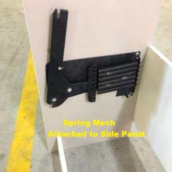
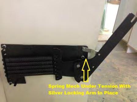
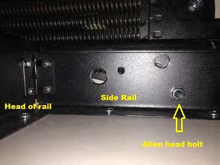
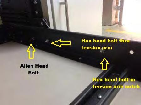
4 Setting the Spring Lift Mechanism WallBeds Australia recommends eye protection is worn whilst setting the Spring Lift Mechanism 1. Place the PVC tube supplied over the Spring Lift Arm. Placing one foot against the bottom front edge of the Side/End panel of the wall bed. Lever the tension arm downwards until you can set the silver arm lock to the round lock tube (hole A) see drawing 9. This is the position of the top cone bolt that was used to attach the Spring Lift mechanism. This may also require the assistance of a helper to achieve this step. Caution: Do not reach behind the tension arm when you are setting the Tension Arm. Tip: A longer pipe or similar could be used providing it is not fragile and of similar or stronger construction. This will allow for extra leverage when engaging the Tension Arm. Round Lock Tube (Hole A ) Bolt in Hole #3 in Steel Frame drops into this slot when loading Bed Face/ Base Panel. Tension Arm Bolt through Hole #2 to secure Arm Lock Round Lock Tube (Hole A ) Drawing 9 Notch to rest against Round Allen head of Bolt in Hole #1 176
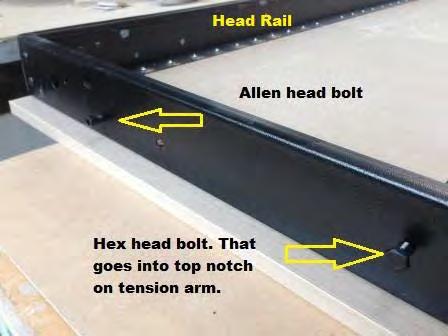
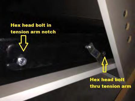
5 Installing the Face/Base Panel onto the Spring Lift Hardware from Card #2 in the SBLM carton is used in these steps. 1. On the Steel Frame insert two 5/16 x 3/4 Hex Head Bolts from the outside through Hole #3 see drawing 10a put the 5/16 Nylock nuts on these bolts only until the nut is flush with the bolt end. DO NOT TIGHTEN AT THIS STEP. 2. Insert the two Round Allen Head Bolts from the outside of the Frame through Hole #1 see drawing 10a use 5/16 Nylock nuts and securely tighten. 3. Stand the Face/Base panel to a vertical position between the tension arms. Lift and tilt back evenly until the two hex head bolts in Hole #3 on either side of the Steel Frame drop into the notched end of Tension Arm (see drawing 10 page 19). NOTE: When installing the Face/Base panel the bottom edge of the Face/Base panel must be placed OVER and BEHIND the kick panel. 4. Once the Bolts in Hole #3 are completely seated in the bottom of the notch in both of the Tension Arms. Lower the Face/Base until the Allen Head Bolts are seated into the lower notch see drawing 9 Important: Do not twist the Face/Base panel as it is being lowered as the Round Allen bolts will come unseated. If this occurs then you will need to lift the Face/Base back up and re lower back into position. 5. Gently lower the Face/Base downwards to insert the 2 remaining 5/16 x 3/4 Head Bolts in Hole #2 on both sides drawing 10 You may need to tilt the panel downward to approximately 45 degrees to reveal the bolt holes. This will also release the Arm Locks, you will hear a click as they disengage. 6. Hold the Face/Base panel securely and tighten the 4 x bolts in Holes #2 and #3. 7. Once all 4 Nylock nuts have been tightened gently close the Face/Base panel. Do Not let it slam shut as the bed cabinet may have moved out of square whilst loading the Face/Base panel and the leg may strike on a top edge of an end panel on the wall bed unit.** IMPORTANT - The Face/Base will NOT stay in the open or the down position until the mattress has been loaded onto the Face/Base panel, the weight of the mattress is needed to counter balance the Spring Lift Mechanism. **If the Face/Base panel is hitting the top on one side of the wall bed End Panel when closing, the wall bed may be now out of square. To fix this, nudge the bottom of the End Panel that the door is hitting on towards the opposite side. You will then see the gap of the Face/Base open and no longer strike the End Panel. Tip: Once the door panel no longer strikes on the End Panel and the gap on either outer edge of the Face/Base panel is even. You can also secure the Lower Back Panel (D) to the wall studs, this will prevent any further cabinet movement. 18
6 Face/Base Panel Hex Head Bolt in Hole #3 Bolt Hole #2 Round Allen Bolt in Hole #1 Drawing a Bed Steel Panel Rail Bolt Hole #3 seated in slot Bolt Hole #2 Round Allen Bolt in Bolt Hole #1 Seated in notch. Refer drawing 9 Side Panel Drawing 10 19
7 Install Handles, Legs, Spring Lift Mechanism Covers & Mattress Hardware Card #4 is used for this step 1. Install legs with the nylon washers on the inside and outside of the steel rails. See drawing Tighten the nylon nut to have a small amount of friction when leg assembly is rotated from the up to down position. 3. Install leg connector rod between legs and secure with 1/4 x 1 1/4 Hex head bolts and star washers see drawing 13 Be sure they are securely tightened so not to become loose. If they are too loose then the legs will twist as you open and close the legs. 4. Position and secure the handle for ease of operation at your preferred height. 5. Attach the powder coated spring mechanism covers in place SBLM Carton.- Secure these with #8 x 1 1/4 black wood screws through the hole in each of the cover plates hardware Card #2 These screws will fix into the timber side panels of the bed. 6. Install mattress and secure with previously installed mattress strap. Drawing 11 Bed Closed Position Drawing 12 Bed/Base Panel 1 3/8 O.C. Leg Pivot Hole Nylon Floor Bed Open Position Steel Leg Washer Nylock Nut Steel washer Steel Filler Steel Frame Drawing 13 Leg Assembly 20

8 Assembly Images 21
9 22
 For Wallbed models: KING SIZE INSTRUCTION BOOKLET #C1 Watch step by step installation instructions at: https://www.wallbedsbywilding.com/wallbed-installation-studio-series/ WARNING! ALL MURPHY/WALLBED
 INSTRUCTION BOOKLET #C0 Watch step by step installation instructions at: https://www.wallbedsbywilding.com/wallbed-installation-studio-series/ WARNING! ALL MURPHY/WALLBED SYSTEMS CONTAIN STORED ENERGY.
Side Mount INSTRUCTION BOOKLET #C122 BED STYLE: PARK CITY
 Side Mount BED STYLE: PARK CITY INSTRUCTION BOOKLET #C1 WARNING! ALL MURPHY/WALLBED SYSTEMS CONTAIN STORED ENERGY. FAILURE TO USE AND FOLLOW THESE INSTRUCTIONS DURING THE INSTALLATION PROCESS COULD RESULT
https://www.wallbedsbywilding.com/wallbed-installation-studio-series/
 For Wallbed models: KING SIZE INSTRUCTION BOOKLET #C1 Watch step by step installation instructions at: https://www.wallbedsbywilding.com/wallbed-installation-studio-series/ WARNING! ALL MURPHY/WALLBED
 INSTRUCTION BOOKLET #C10 Watch step by step installation instructions at: https://www.wallbedsbywilding.com/wallbed-installation-studio-series/ WARNING! ALL MURPHY/WALLBED SYSTEMS CONTAIN STORED ENERGY.
Murphy Bed Lift Mechanisms Steel Folding Leg System All Necessary Hardware
 [Model #DIY: Do-It-Yourself Wall Bed Kit] Cut & Assembly Instructions For SINGLE - DOUBLE - QUEEN size Wallbeds. VERTICAL & HORIZONTAL installations CONTAINS MECHANISM AND HARDWARE KIT Murphy Bed Lift
INSTRUCTION BOOKLET #34. For Wallbed models: KING SIZE SIERRA WITH STORAGE HEADBOARD
 For Wallbed models: KING SIZE SIERRA WITH STORAGE HEADBOARD INSTRUCTION BOOKLET #34 WARNING! ALL MURPHY/WALLBED SYSTEMS CONTAIN STORED ENERGY. FAILURE TO USE AND FOLLOW THESE INSTRUCTIONS DURING THE INSTALLATION
INSTRUCTION BOOKLET #C21. For Wallbed models: KING SIZE
 For Wallbed models: KING SIZE INSTRUCTION BOOKLET #C1 WARNING! ALL MURPHY/WALLBED SYSTEMS CONTAIN STORED ENERGY. FAILURE TO USE AND FOLLOW THESE INSTRUCTIONS DURING THE INSTALLATION PROCESS COULD RESULT
WILDING WALLBEDS INSTALLATION INSTRUCTION Side Mount
 WILDING WALLBEDS INSTALLATION INSTRUCTION Side Mount For Wallbed models: Do-It-Yourself Insturction booklet C92 WARNING! ALL MURPHY/WALLBED SYSTEMS CONTAIN STORED ENERGY. FAILURE TO USE AND FOLLOW THESE
Strata. urniture. Adriana Instructions. Parts in the Arm Box: Parts in the Body Box: Watch our assembly videos at
 1A Watch our assembly videos at www.strataf.com/videos Parts in the Arm Box: Arm - Outside View Arm - Inside View 1B Parts in the Body Box: Back Deck x 1 Seat Deck x 1 with the Feet attached Back Panel
Strata. urniture. Addison Instructions. Parts in the Arm Box: Parts in the Body Box: Watch our assembly videos at
 1A Watch our assembly videos at www.strataf.com/videos.html Parts in the Arm Box: Arm - Outside View Arm - Inside View Corbels x 4 1B Parts in the Body Box: Back Deck x 1 Seat Deck x 1 Back Panel x 1 with
INSTRUCTION BOOKLET #C20
 INSTRUCTION BOOKLET #C0 WARNING! ALL MURPHY/WALLBED SYSTEMS CONTAIN STORED ENERGY. FAILURE TO USE AND FOLLOW THESE INSTRUCTIONS DURING THE INSTALLATION PROCESS COULD RESULT IN SEVERE PERSONAL INJURY TO
Strata. urniture. Mission Rim Instructions. Parts in the Arm Box: Parts in the Body Box:
 1A Watch our assembly videos at www.strataf.com/videos.html Parts in the Arm Box: Arm - Outside View Arm - Inside View Corbels x 4 1B Parts in the Body Box: Back Deck x 1 Seat Deck x 1 with the Feet attached
INSTALLATION INSTRUCTIONS
 INSTALLATION INSTRUCTIONS For Wallbed models: Do-It-Yourself BOOKLET #C90 WARNING! ALL MURPY/WALLBED SYSTEMS CONTAIN STORED ENERGY. FAILURE TO USE AND FOLLOW THESE INSTRUCTIONS DURING THE INSTALLATION
Strata. urniture Watch our assembly videos at Denali Arms. Parts in the Arm Box: Hardware in this Box:
 1A Denali Arms Watch our assembly videos at www.strataf.com/videos.html Parts in the Arm Box: Arm - Outside View Arm - Inside View 1B Hardware in this Box: (80mm) x 8 Barrel Nuts x 8 x 8 Wood Buttons x
Wallbeds Northwest ENDURA CABINET PLANS AND INSTRUCTIONS
 Thank you for purchasing your Wall Bed from Wallbeds Northwest. If you have purchased a complete "Endura DIY Kit," then much of the work is already done for you. Please skip to assembly instructions. Note
This instruction manual is an in-depth look and explanation of how to assemble and install the Murphy Bed properly and efficiently.
 This instruction manual is an in-depth look and explanation of how to assemble and install the Murphy Bed properly and efficiently. Don t be put off by the size of the instruction manual as the large diagrams
Assembly Instructions 10 X 10 Aluminum Roof Support
 Assembly Instructions 10 X 10 Aluminum Roof Support Aluminum Roof Support Bolt Package 16-5/16 X 2 ¼ SS Bolt 24-5/16 X 1 SS Bolt 40-5/16 SS Nylon Lock Nuts 16-5/16 SS Flat Washers 28-4 ½ Wood Screws 36-1
LOWLINE SINGLE FOLD DOWN WALL BEDS
 ASSEMBLY INSTRUCTIONS LOWLINE SINGLE FOLD DOWN WALL BEDS Tools Required For Assembly No 2 & No 4 Phillips Head Screwdrivers No 2 Slot Head Screwdriver Hammer Electric Drill (Hammer Drill for Masonry) 6.5mm
Installation Instructions - Model V4JSD 1
 Installation Instructions - Model V4JSD 1 Support Assemblies: Parts list: (Note see enclosed cut sheet for quantities and dimensional information) A vertical structural member (1 ½ x 1 ½ modular frame)
ASSEMBLY INSTRUCTIONS
 Section 1: LY OUT PRTS Unpack and familiarize yourself with the components. Single, ouble and King size Next Beds are packed in 3 boxes (Single 2 boxes). Remove the entire contents of boxes and lay the
Preference Collection 5580 Treatment Console INSTALLATION GUIDE
 Preference Collection 5580 Treatment Console INSTALLATION GUIDE 0 WARNING Failure to install the 5580 as described in this installation guide may cause the unit to collapse, resulting in serious injury
ASSEMBLY INSTRUCTIONS DIY WALL BED KIT QUEEN BI FOLD DOOR CABINET & MECHANISM. Tools Required For Assembly. 6.5mm Masonry Drill Bit
 ASSEMBLY INSTRUCTIONS DIY WALL BED KIT QUEEN BI FOLD DOOR CABINET & MECHANISM Tools Required For Assembly No 2 & No 4 Phillips Head Screwdrivers No 2 Slot Head Screwdriver Hammer Electric Drill (Hammer
SUPREME STEEL. Bed Frame & Mechanism INSTRUCTIONS. Models SBF-M and SBF
 SUPREME STEEL Bed Frame & Mechanism INSTRUCTIONS Models SBF-M and SBF TOLL FREE 1-800-667-6336 PHONE: (604) 576-7880 FAX: (604) 576-7867 E-mail: info@murphybeds.com Website: murphybeds.com Established
WALLBED Assembly Instructions
 WALLBED Assembly Instructions 1 Congratulations and a Big Thank You for your purchase of a Wallbed Gallery Murphy Bed! We sincerely appreciate your business! First a few words of advice and caution: 1.
Assembly Instructions 10 X 10 Aluminum Frame Building
 Assembly Instructions 10 X 10 Aluminum Frame Building 27 97 9 8 47 36 74 52 10 10 X 10 Square Building W/ Dome Includes: The Steel Entry Door with a Dead Bolt Lock assembly and Aluminum Door Frame. Metal
TOOLS REQUIRED FOR ASSEMBLY. Rubber Mallet or Plastic Tip Hammer PARTS REQUIRED FOR ASSEMBLY OF SINGLE ENTRY STARTER.
 TOOLS REQUIRED FOR ASSEMBLY Rubber Mallet or Plastic Tip Hammer Top Cover Support PARTS REQUIRED FOR ASSEMBLY OF SINGLE ENTRY STARTER Back Stop Divider Closed 'L' Upright Slotted Reinforcement Support
GlideRite Retractable Cover System For HotSpring & Tiger River Spas (except Classic & pre-2000 Landmark Spas)
") List of Contents Quantity Description 12 #10 x 1 ½ Flat Head Phillips Screw (see pg. 2) 2 #10 x ½ Pan Head Phillips Screw (see pg. 2) 8 ¼ x 2 ½ Lag Bolt (see pg. 2) 7 ¼ 20 x 5 / 8 Hex Head Bolt (see pg.
List of Contents Quantity Description 12 #10 x 1 ½ Flat Head Phillips Screw (see pg. 2) 2 #10 x ½ Pan Head Phillips Screw (see pg. 2) 8 ¼ x 2 ½ Lag Bolt (see pg. 2) 7 ¼ 20 x 5 / 8 Hex Head Bolt (see pg.
Video Wall Installation Instructions 2W X 3H, 3W X 3H
 Video Wall Installation Instructions 2W X 3H, 3W X 3H www.microndisplaysolutions.com Table of Contents Important Safety Instructions... 3 Configuration... 4 Package Contents, included and optional items...
BY ALIEN TECHNOLOGIES CORP
 BY ALIEN TECHNOLOGIES CORP Assembly Instructions TopLift Pros YOU MAY ALSO REVIEW OUR ASSEMBLY VIDEO, PLAY AND PAUSE AT YOUR CONVENIENCE. JUST VISIT US AT WWW.TOPLIFTPROS.COM AND GO TO Customer Support
Assembly Instructions for model: VMPR1
 Assembly Instructions for model: VMPR1 Congratulations on your purchase! The VMPR1 ceiling mount provides a unique, simplified method of ceiling mounting inverted LCD/DLP projectors. Its low profile design
Mounting Instructions Item No.: xxx
 Mounting Instructions Item No.: 271.92.xxx Wall-Beds 1 General Notes For vertical folding beds Successful and safe installation of Bed-Lift and construction of casework requires a professional skill level
Oxford Stalls Installation Instructions
 Oxford Stalls Installation Instructions RAMM Horse Fencing and Stalls 13150 Airport Hwy. Swanton, OH 43558-9615 1-800-434-8456 Rev. 8/15/17 Before You Start Typical stall sizes are 10 x 10, 12 x 12 or
ED1300/1300F SERIES CONCEALED VERTICAL ROD DEVICE INSTALLATION INSTRUCTIONS
 ED1300/1300F SERIES CONCEALED VERTICAL ROD DEVICE INSTALLATION INSTRUCTIONS Ver.2 1300 SERIES CONCEALED VERTICAL ROD DEVICE Top Strike Latch Screws Strike Screws Release Plunger Top Latch Plunger Screws
D3976 RECESSED EXIT INSTALLATION INSTRUCTIONS
 PACKAGE CONTENTS PRODUCT MUST BE INSTALLED ACCORDING TO ALL APPLICABLE BUILDING AND LIFE SAFETY CODES TEMPLATE INSTALLATION INSTRUCTIONS STRIKE HAND TOOL 5/32 HEX KEY ROD END CAPS EXIT DEVICE CRANK ARM
How to assemble PIANO
 Before you begin, make sure there is a clean, carpeted floor to work on, or use clean cardboard or blankets to protect the furniture surfaces during the assembly process. Unpack and Identify the parts
Wellington Wallbed 700 Series Assembly Instructions
 Wellington Wallbed 700 Series Assembly Instructions 1. Read all instructions before proceeding. Not following instructions may result in personal harm or damage to the furniture. 2. 2 people are required
Please Do Not Return Your Item to the Retailer
 Please Do Not Return Your Item to the Retailer Thank you for your purchase of an Epic Furnishings item You should enjoy many years of trouble free, dependable use If for any reason you are missing parts,
3/8-16 x 3/4 cap screw. 3/8-16 hex nut for above screws. 1/4-20 x 3/4 socket cap screw. 3/16 short arm hex key (not to scale)
") Super Slab Roller 24, 30 and 36 models Worktable Assembly Directions P.O. Box 89 Cheney, WA 99004 USA 509.235.9200/800.23.7896 Fax: 509.235.9203 www.northstarequipment.com Revised September, 2006. All
Super Slab Roller 24, 30 and 36 models Worktable Assembly Directions P.O. Box 89 Cheney, WA 99004 USA 509.235.9200/800.23.7896 Fax: 509.235.9203 www.northstarequipment.com Revised September, 2006. All
SOCCER TABLE. Assembly Instructions
 Updated: 5/4/16 SOCCER TABLE Assembly Instructions Table of Contents Parts Identifier... 3 Hardware Identifier. 4 Table Assembly Instructions... 5 Table Assembly Pictures..... 6, 7, 8 2 Page Parts Identifier
Free Standing Frame and Canopy
 Patriot Docks Free Standing Frame and Canopy Required Tools: Cordless Drill, 3/8 drill bit, 17mm wrench, 18mm wrench, 6mm hex key (included), 8mm hex key (included) Helpful Tips: Assembling and installing
EURO DELUXE INSTALLATION INSTRUCTIONS
 WALLBEDS! TM EURO DELUXE INSTALLATION INSTRUCTIONS NOTE: Due to the arched top assembly, the assembly of this model is different from the standard wallbed assembly. PLEASE READ THROUGH THESE INSTRUCTIONS
Universal flat-panel mount
 I N S T A L L A T I O N M A N U A L Universal flat-panel mount www.christiedigital.com PM 2004/ REV 02 Contents - Assembly drawing - Fine tune tilt adjustments - Parts list - Installing the adapter plate
PERSONAL RECORD KEEPING
 2 P R O 3 7 0 A s s e m b l y i n s t r u c t i o n s PERSONAL RECORD KEEPING Tip: Record the serial numbers of your Octane Fitness elliptical in the spaces below. This will make it easier for you to obtain
WPS crew Doors Installation instructions
 WPS-132-133 crew Doors Installation instructions ORDER OF INSTALLATION FOR A COMPLETE ENCLOSURE OF A CREW WPS (Weather Protection System) IS AS FOLLOWS: 1. Heater 2. Rear Thresholds - Right Hand & Left
3 wide x 3 deep Video Wall Display Installation Guide
 HoverTrack Series 3 wide x 3 deep Video Wall Display Installation Guide VWD-3X3-X462 This display kit mounts NEC X461UN and X462UNS LCD monitors in a 3 wide by 3 deep landscape configuration. The frame
Installation for Full Size Polaris Ranger Crew Doors
 Installation for Full Size Polaris Ranger Crew Doors Order of Installation: Heater Doors Wiper on to Windshield Windshield Top & Back Panel Note: Most of the steps in these instructions need to be repeated
LCD DISPLAY MOUNT
 I N S T A L L A T I O N M A N U A L 38-804769-01 LCD DISPLAY MOUNT WWW.CHRISTIEDIGITAL.COM Contents - Assembly drawing - Securing the bottom wall plate - Fine tune adjustments - Marking the top plate mounting
K9 KIT INSTALLATION INSTRUCTIONS CROWN VIC KK-K9-F7-K
 K9 KIT INSTALLATION INSTRUCTIONS 1998-2011 CROWN VIC KK-K9-F7-K TOOLS REQUIRED: Power Drill (Cordless preferable) Drill Bit Set Standard Wrench and Socket Set Metric Socket Set Screwdriver Set Torx Bit
MPA-9000 Universal Ceiling Projector Mount Kit
 I N S T R U C T I O N M A N U A L Universal Ceiling Projector Mount Kit The Universal Ceiling Projector Mount provides a unique, simplified method of ceiling mounting your inverted projector. This low
SmartView Mounting Frame 3 Wide x 3 Deep Video Wall Display Installation Guide
 SmartView Mounting Frame 3 Wide x 3 Deep Video Wall Display Installation Guide WMK-034 This display kit mounts ViewSonic 46 Video Wall displays in a 3 wide by 3 deep landscape configuration. The frame
MM750 Installation Instructions
 MM750 Installation Instructions IMPORTANT SAFETY INSTRUCTIONS - SAVE THESE INSTRUCTIONS Please read this entire manual before you begin. Do not unpack any contents until you verify all requirements on
INSTALLATION INSTRUCTIONS
 TEL -866-XANATOS INSTALLATION INSTRUCTIONS PART#: 7D5000SS\7D500A GRILL GUARD FOR DODGE SPRINTER 07-09 PARTS LIST: 8 6 Grille Guard Driver/Left Frame Mounting Passenger/Right Frame Mounting Driver/Left
43107 Rhino Jerry Can Holder Rhino Jerry Can Holder - Horizontal
 Important: Please read these instructions carefully prior to installation. Check the contents of kit before commencing fitment and report any discrepancies. Clean the alloy tray prior to installation.
 Menu Board Tilt or Fixed Mount Installation Instructions MDS1T-200, MDS1T-300, MDS1T-400 MDS2T-200, MDS2T-300, MDS2T-400 MDS3T-200, MDS3T-300, MDS3T-400 MDS4T-200, MDS4T-300, MDS4T-400 MDS5T-200, MDS5T-300,
WAREHOUSE HANGER INSTALLATION INSTRUCTIONS R H INS T A L L A TIO N INS T R U C TIO N S
 INS T A L L A TIO N INS T R U C TIO N S WAREHOUSE HANGER NOTE: Due to the size and weight of the Warehouse Hanger it is recommended that this Hanger be installed on 3 4 or wider doors. 10.11.2016 2-3/16"
Why are we giving this guidebook as a FREE download?
 Construction Guide Queen, Double & Twin Vertical 1 Note: This guide covers the construction steps for all 3 sizes of the vertical wall mount Easy DIY Murphy beds, Queen, Double and Twin. The construction
Sentinel Series Cigar Humidor End Tables
 Sentinel Series Cigar Humidor End Tables Assembly Instructions Models: Sentinel 500, 1000 and 1500 Style: Contemporary SENTINEL ASSEMBLY INSTRUCTIONS Congratulations! You have purchased a superior cigar
Models CW and AW Installation Instructions
 Models CW and AW Installation Instructions Please keep these instructions for future reference. Hiddenbed must be dis-assembled before moving. a product of WALLBEDS! MODELS AW and CW HIDDENBED COMPONENTS
MM540 Installation Instructions IMPORTANT SAFETY INSTRUCTIONS - SAVE THESE INSTRUCTIONS
 MM50 Installation Instructions IMPORTANT SAFETY INSTRUCTIONS - SAVE THESE INSTRUCTIONS Please read this entire manual before you begin. Do not unpack any contents until you verify all requirements on PAGE.
MM340 Installation Instructions IMPORTANT SAFETY INSTRUCTIONS - SAVE THESE INSTRUCTIONS
 MM30 Installation Instructions IMPORTANT SAFETY INSTRUCTIONS - SAVE THESE INSTRUCTIONS Please read this entire manual before you begin. Do not unpack any contents until you verify all requirements on PAGE.
N. 15th Street, Middlesboro, KY FLIP TARP DUMP BODY INSTALLATION INSTRUCTIONS
 1-800-248-7717 1002 N. 15th Street, Middlesboro, KY 40965 FLIP TARP DUMP BODY INSTALLATION INSTRUCTIONS Congratulations on your purchase of a Mountain Flip Tarp Dump Body tarping system. With tarping systems
Follow these steps to assemble your Hiddenbed 1 Construct the 3 main parts 2 Assemble them together 3 Add a mattress. YOUR HIDDENBED IS READY! 2
 Mounting Instructions Item No.: 271.97.300 Hiddenbed Furniture parts supplied by the customer Follow these steps to assemble your Hiddenbed 1 Construct the 3 main parts 2 Assemble them together 3 Add a
Cabinet Mount Lifter Instructions
 PART LIST 2 @ Side Pivot Arms 1 @ Coupler Tube 1 @ Left Hand Bracket 1 @ Right Hand Bracket 2 @ Cover Support Arms w/ Foam Grip 1 set of Cover Saver 4 @ 4 Wood Screw 8 @ 1 Wood Screw 12 @ 1 Black Tek Screw
STEP 1 STEP 2 LEVELER KIT OPTION MOBILE CASTER KIT OPTION
 B SERIES INDUSTRIAL BENCHES TOOLS REQUIRED FOR ASSEMBLY Socket set, Open end wrench set, Cordless drill with 3/8" socket bit (Magnetic recommended). BEFORE ASSEMBLY Read through the assembly instructions
Installation And Care Instructions. Vertical Honeycomb Shades
 Installation And Care Instructions Vertical Honeycomb Shades Rev 5/2013 Table Of Contents Getting Started... 3 Parts Overview... 4 Materials Required... 5 Tools Required... 6 Outside Mount Installation...
PRE-ENGINEERED HORSE STALL SYSTEMS SDFD SLIDING DOOR c/w FOLD-DOWN GRILL. & Assembly. Installation Instructions
 PRE-ENGINEERED HORSE STALL SYSTEMS 4800 SDFD SLIDING DOOR c/w FOLD-DOWN GRILL & Assembly Installation Instructions 4800 SDFD Sliding Door c/w Fold-Down Grill Components - 1 3 /4" x 2" x 88" channels (2)
Franklin Mills Stackable Movable Lateral Instructions
 Franklin Mills Stackable Movable Lateral Instructions Table of Contents: Table of contents...1 Tools Required...2 Stationary Shelving Assembly...3-7 Mobile Shelving Assembly...8-16 Rail Assembly...8-11
SINCE 1922 P UBLICATION N O
 SINCE 1922 GARED SPORTS MICRO-Z SET-UP INSTRUCTIONS VERY IMPORTANT! READ INSTRUCTIONS CAREFULLY AND FOLLOW STEP BY STEP SET-UP PROCEDURE P UBLICATION N O. 5 5 1 7 5 2 9 1 6 Recommended tools and accessories.
Sentinel Series Cigar Humidor End Tables
 Sentinel Series Cigar Humidor End Tables Assembly Instructions Models: Sentinel 500, 1000 and 1500 Style: Traditional SENTINEL ASSEMBLY INSTRUCTIONS Congratulations! You have purchased a superior cigar
MantelMount. TM1A Installation Instructions IMPORTANT SAFETY INSTRUCTIONS - SAVE THESE INSTRUCTIONS
 MantelMount TMA Installation Instructions IMPORTANT SAFETY INSTRUCTIONS - SAVE THESE INSTRUCTIONS TM Thank you for choosing the MantelMount television wall mount. Please read this entire manual before
Pocket Door Kit PD1 / PD2 Installation Instructions. Kit Contents.
 Pocket Door Kit PD1 / PD2 Installation Instructions Kit Contents. 1, Create Rough Opening In Stud Wall Construct rough opening ensuring all sides are square and level. Rough opening should be; Height =
INSTALLATION INSTRUCTIONS INS T A L L A TIO N INS T R U C TIO N S ROD IRON SCROLL HANGER R H
 INS T A L L A TIO N INS T R U C TIO N S ROD IRON SCROLL HANGER 10.5.2016 2-1- 3/16" 11/16" 8" 8 O 2-7/8 Ø2-7/8" 3-1/2 3-1/2" 12-9/16 12-9/16" PLEASE NOTE: These instructions are specific to a particular
LCD/Plasma Mount Manual
 LCD/Plasma Mount Manual Product Overview: Thank you for your Cheetah Mount purchase. All Cheetah Mounts are designed to provide excellent function, high quality, easy installation and stylish appearance.
GlideRite Retractable Cover System For Hot Spot Spas (SE & SLX only)
") List of Contents Quantity Description 12 #10 x 1 ½ Flat Head Phillips Screw (see pg. 2) 2 #10 x ½ Pan Head Phillips Screw (see pg. 2) 8 ¼ x 2 ½ Lag Bolt (see pg. 2) 7 ¼ 20 x 5 / 8 Hex Head Bolt (see pg.
List of Contents Quantity Description 12 #10 x 1 ½ Flat Head Phillips Screw (see pg. 2) 2 #10 x ½ Pan Head Phillips Screw (see pg. 2) 8 ¼ x 2 ½ Lag Bolt (see pg. 2) 7 ¼ 20 x 5 / 8 Hex Head Bolt (see pg.
Required Tools: Suggested Additional Tools: 1 Cordless Drill with Robertson Bits 1 Ratchet Wrench 1 7/16 or 11mm socket 1 7/16 or 11mm Gear Wrench
 Thank you for your recent purchase of a Cabinets by Hayley garage cabinet system. You are about to experience the best made cabinets that you can purchase. Cabinets by Hayley are designed for beauty and
The SwingAway ('CEVNT') Bed Assembly Instructions
 Bed Assembly Instructions") The SwingAway ('CEVNT') Bed Assembly Instructions Issued 18/07/10, Hideaway Beds Ltd Updated: 2/3/12, 15/05/12, 19/05/16, 13/07/17 By using this Assembly Guide, you hereby agree to the following: Our own
The SwingAway ('CEVNT') Bed Assembly Instructions Issued 18/07/10, Hideaway Beds Ltd Updated: 2/3/12, 15/05/12, 19/05/16, 13/07/17 By using this Assembly Guide, you hereby agree to the following: Our own
Boat Lift Canopy Frame Assembly Instructions
 Patriot Docks Boat Lift Canopy Frame Assembly Instructions Helpful Tips: Assembling and installing the canopy frame and cover is a two person job. Additional help makes installation easier and is recommended.
Privacy Wall Glass Selections - Polished Edge Slider Door
 Privacy Wall Glass Selections - Polished Edge Slider Door 3/6" HEX BIT PUTTY KNIFE #2 ACR BIT SUCTION CUP HOLDERS DOOR LEAF: Satin Tempered Clear Tempered LOCTITE 425 SIDE LIGHT ETCHED GLASS STYLES: Satin
INSIDE PANEL NOT SHOWN TO DETAIL ANCHORING SYSTEM
 SIX INCH ALPHA MODULE INSTALLATION KEWAUNEE SCIENTIFIC CORPORATION SIX INCH ALPHA MODULE ANCHORING SYSTEM After Alpha module has been set in desired location. Adjust the four adjustment bolts until the
Warnings. Description. Prior to Installation Tools Needed
 Warnings Failure to act in accordance with the following may result in death or personal injury. The JT Strong Arm Stabilizer System is intended to eliminate chassis movement in travel trailers and fifth
Important Note: Why this guidebook is FREE?
 Easy DIY Murphy Bed Construction Guide 1 Important Note: This guide is a FREE SAMPLE of our Complete Construction Guidebook. With the help of this guide you will get familiar with the construction steps
Preference Collection and Treatment Console INSTALLATION GUIDE
 Preference Collection 5580.69 and 5580.96 Treatment Console INSTALLATION GUIDE WARNING Failure to install the 5580 as described in this installation guide may cause the unit to collapse, resulting in serious
6 Foot/ 1800mm Aisle Width Net-Contain Aisle Containment for N-Type and S-Type Cabinets
 6 Foot/ 1800mm Aisle Width Net-Contain Aisle Containment for N-Type and S-Type Cabinets Panduit Corp. 2016 INSTALLATION INSTRUCTIONS Page 1 of 36 Component Guide for Doors Dual Sliding Containment Door
Star Trac Turbo Trainer Assembly & Setup
 Star Trac Turbo Trainer Use the following procedures to unpack and assemble your Turbo Trainer manufactured by Star Trac. UNPACKING AND PARTS LIST Position the shipping carton so the Heavy End logo is
Installing The Aliens Extermination Deluxe 50" Cabinet with Sintra Marquee
 Installing The Aliens Extermination Deluxe 50" Cabinet with Sintra Marquee Document Part #: 040-0262-01 This document describes how to install The Aliens Extermination Deluxe Cabinet with Sintra Marquee
Installation Instructions
 by Plato Woodwork Installation Instructions Plato Woodwork, Inc. 200 Third Street SW P.O. Box 98 Plato, MN 55370 www.platowoodwork.com 800.328.5924 SECTION GUIDE GETTING STARTED PAGE # Installation Methods...
TechBench Installation Manual
 Manual Table of Contents TechBench Overview....2 Bench Assembly Linear,36 (914,4mm) Wide 96 (2438,4mm) Wide 3,4,5,6,7 Bench Assembly Linear,24 (609,6mm) Wide 30 (762mm) Wide..8,9 Bench Assembly Corner
OXYGEN INSTALLATION. Revision date
 12345 1 Hardware List 12345 Flat head wood screw #9 x 7/8 long with #2 Phillips drive, silver Used to attach surfaces and end panels Hex set screw ½-13 x 2 long with 1/4 hex drive, black Used on Legs Hex
TIP FOR GETTING STARTED
 Tip for getting started TIP FOR GETTING STARTED Be careful not to drill into any electrical wires, ductwork, plumbing or other damagable components. If you have any questions on the locations of these
v1.0 ASSEMBLY GUIDE Mia Wide Bookcase
 v1.0 ASSEMBLY GUIDE Mia Wide Bookcase Components Upon unpacking your bookcase from it s delivery box, you should have the pieces shown. Follow the steps on the next pages to assemble your new bookcase.
INSTALLATION AND CARE INSTRUCTIONS
 INSTALLATION AND CARE INSTRUCTIONS Vertical Applications Honeycomb Shades 52 C8-10-3401 Rev 2/14 CONTENTS Introduction...2 Before You Begin...3 Vertical Application Parts Overview...4 Materials Required...5
Dual Arm Tilt LCD Mount
 Installation Manual model # 51324 M o u n t i n g S y s t e m s Dual Arm Tilt LCD Mount Fits Displays 13 to 32 Supports Up to 50 lbs (23 kgs) Projection from Wall from 3 to 17 Meets VESA Standards 50/75/100,
JK TrailGate JK TrailGate
 INSTALLATION INSTRUCTIONS INST-17-66-010_A JK TrailGate IMPORTANT: Thank you for purchasing this Poison Spyder product. Please read through this entire document before proceeding with installation. If
Dura-Lock Roof System
 DLR-14 Dura-Lock Roof System Assembly and Installation Instructions Read the instructions before starting the job. They explain the steps required to produce a finished product that will meet factory specifications.
ASSEMBLY GUIDE. Mia Narrow Bookcase
 ASSEMBLY GUIDE Mia Narrow Bookcase Components: Upon unpacking your bookcase from it s delivery box, you should have the pieces shown. Follow the steps on the next pages to assemble your new bookcase. Step
INSTALLATION TORSION SPRING FRONT OR REAR MOUNT LOW HEADROOM. 1 Cutting Vertical Track. 2 Fully Adjustable Jamb Brackets
 TORSION SPRING FRONT OR REAR MOUNT LOW HEADROOM Wayne Dalton, a division of Overhead Door Corporation P.O. Box 67, Mt. Hope, OH., 44660 Supplemental insert Copyright 2015 Wayne Dalton, a division of Part
INSTALLATION INSTRUCTIONS
 www.marwincompany.com Kit Number Door Height Rough Opening Height KD200BB68 80 84 ½ KD200BB70 84 88 ½ KD200BB80 96 100 ½ INSTALLATION INSTRUCTIONS 200BB SERIES KD POCKET DOOR FRAME FOR 2 X 4 STUD WALLS
Bi-Pass And Bi-Fold Sliders
 Bi-Passs and Bi-Fold Sliders Installation Guide Bi-Pass And Bi-Fold Sliders Tools required: Hand Drill Counter Sink Drill BitSet #8 Philips Screw Driver Measuring Tape Level What s Included: Panels with
L.L.Bean. Wooden Slat Bed
 L.L.Bean Wooden Slat Bed Thank you for purchasing our Slat Bed. Assembly of this product requires A Phillips head screwdriver. We have found it helpful to have a second person present in at least one step