WPS crew Doors Installation instructions
|
|
|
- Angel Black
- 5 years ago
- Views:
Transcription


1 WPS crew Doors Installation instructions
2 ORDER OF INSTALLATION FOR A COMPLETE ENCLOSURE OF A CREW WPS (Weather Protection System) IS AS FOLLOWS: 1. Heater 2. Rear Thresholds - Right Hand & Left Hand 3. Front Thresholds - Right Hand & Left Hand 4. Windshield - Fixed or Tip-out 5. Three Piece Top System 6. Front & Rear Doors Right Hand & Left Hand
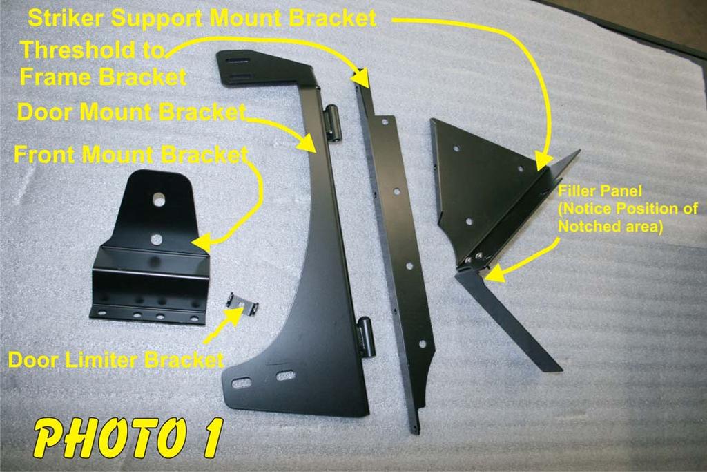
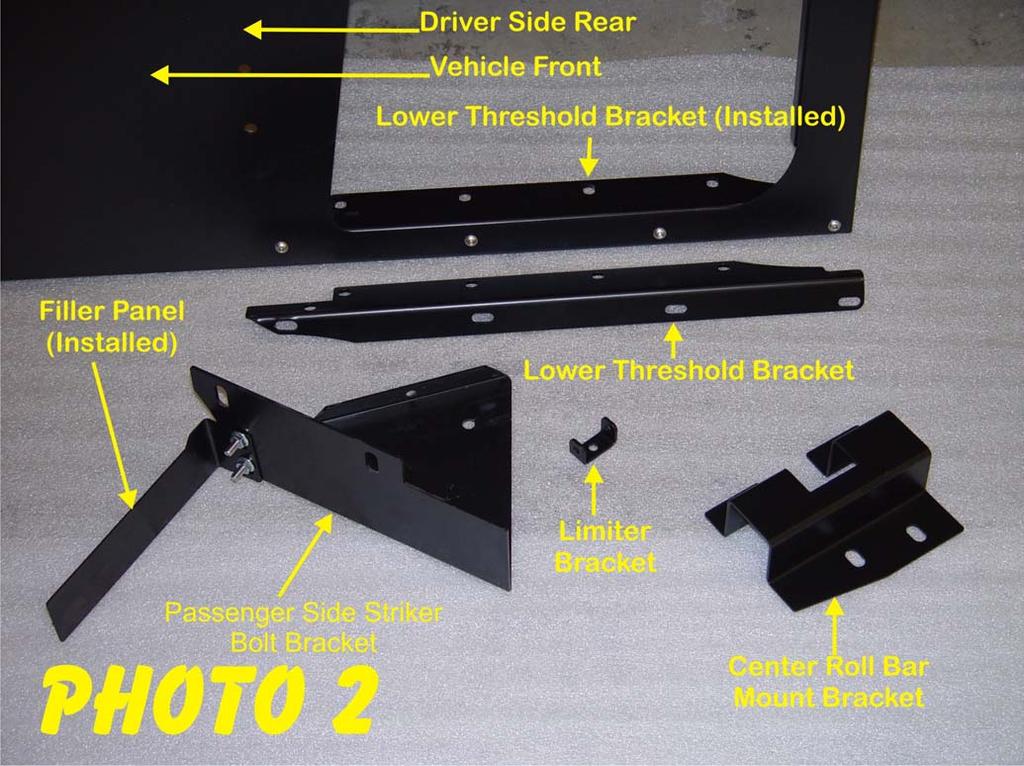
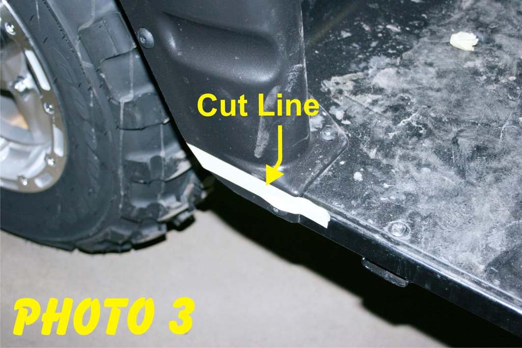
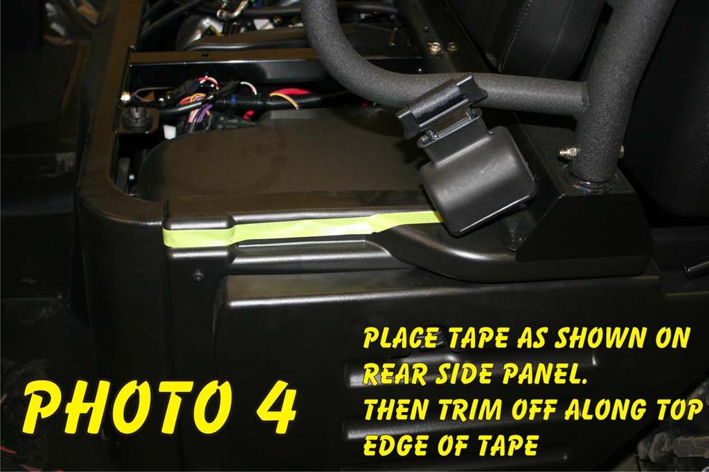
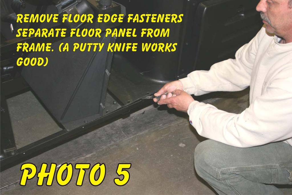
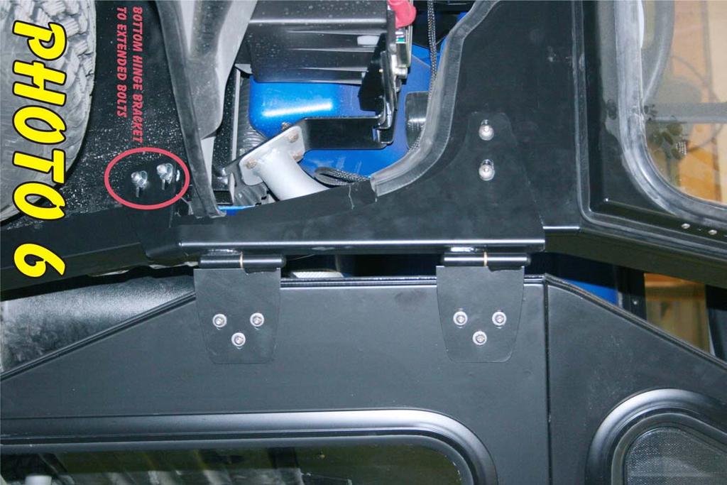
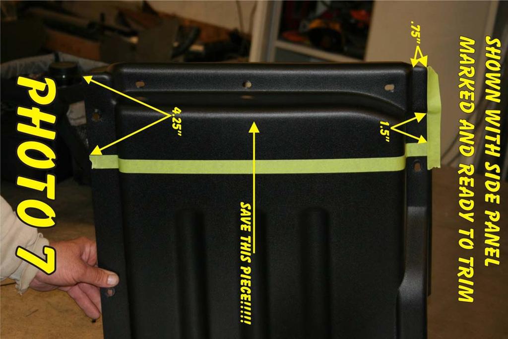
3 Vehicle Preparation All photos are in the back of the instruction book so that they can be easily removed and laid out on your work area for easy reference. Please check Photos 1 and 2 first to get yourself familiar with the parts you will be working with. NOTE: Retain all Fasteners for Reinstallation. 1. If a windshield or Top & Back Panel has been installed, you will need to remove the windshield and loosen the bolts securing the top and back panel to the roll cage. The front edge of the door threshold fits over the roll cage and under the Windshield. 2. Remove the front side kick panels and do not replace until instructed to do so. 3. If a WPS-104 Heater System is to be installed, consult the WPS-104 installation instructions for installing the air duct vents in the side kick panels and dash. 4. Under the kick panel there are (2) 3/8 x ¾ cap bolts securing the roll cage to the frame of the vehicle on each side. Remove and replace these, (putting the bolt through from the inside out) with the stainless steel 3/8 x 1 ¼ cap bolts. Replace the nuts and tighten the cage back to the frame. These longer bolts will act as studs to secure the bottom of the hinge brackets (Shown in Photo 6). 5. The bottom outside edge of the kick panels need to be cut off just below the outside corner. Tape or mark a straight line as shown in Photo 3. Make several cuts or scores with a razor knife. 6. Remove both the front and rear lower bench seats. Remove the cross braces and the storage bin under the front seat. 7. The top lip of each rear side panel needs to be trimmed off flush with the top of the seat support. Remove the seat and tape or mark a line as shown in Photo 4 ((You may wish to remove the side panel to avoid damaging the seat support)) and make several cuts or scores with a razor knife. Make sure the side panel does NOT extend above seat support. 8. Remove the Front Side Panels and mark and trim as shown in Photo 7. Reinstall the 4.25 piece of the panel leaving out the top screw. 9. Remove the screws (4 in front, 5 in rear) securing the outside edge of the floor panel to the frame, front and rear, on both sides of the vehicle Photo Sub-assembly Front and Rear. Fasten the lower threshold brackets to the threshold using (4) 1/4 20 x ½ BHCS (Button Head Cap Screw) and Flange Nuts. Tighten securely. Fasten the filler panels to the striker bolt brackets using (2) ¼ - 20 x ½ BHCS (Button Head Cap Screw) and flange nuts. Do not tighten. Refer to Photo 2.
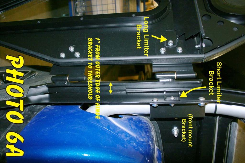
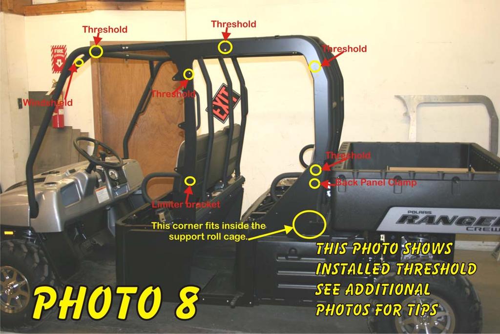
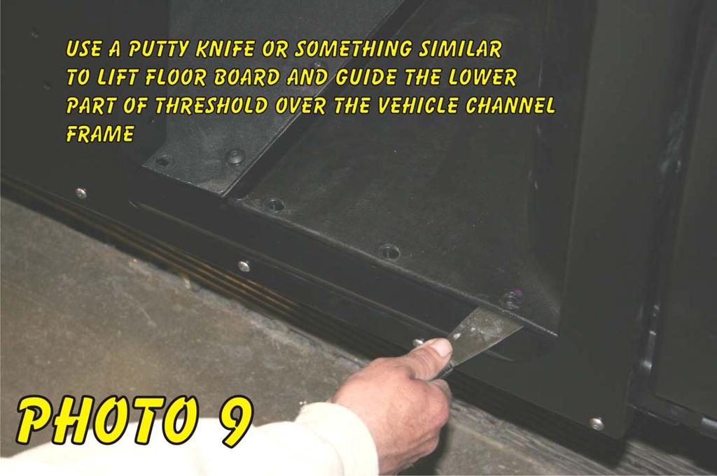
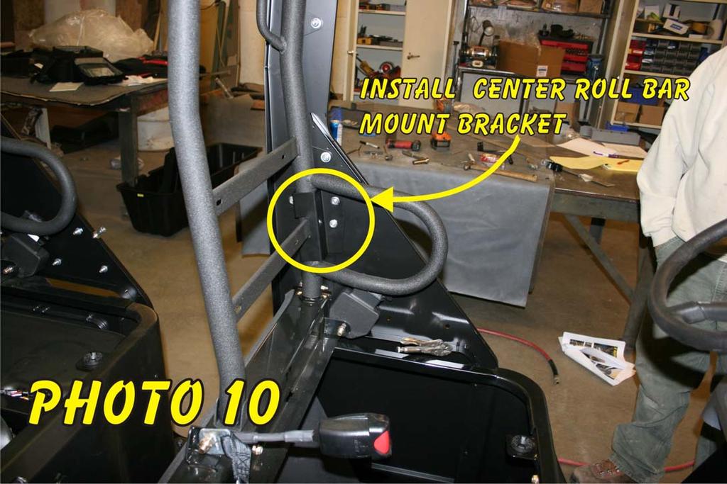
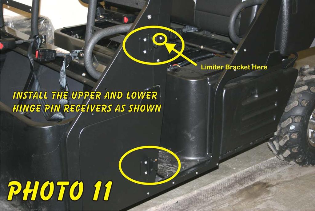
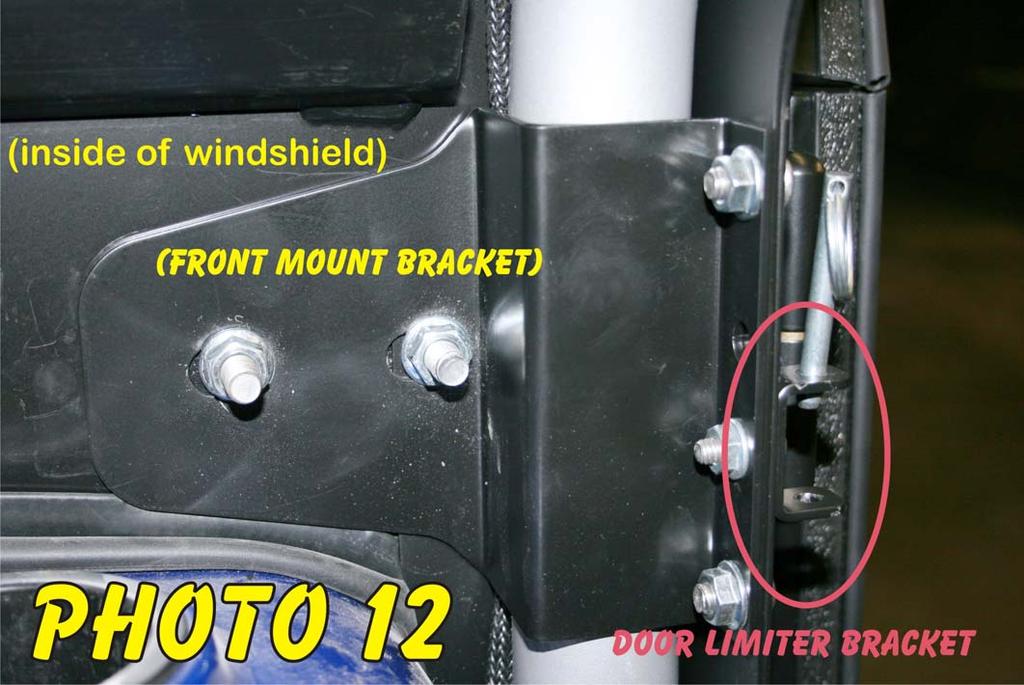
4 Threshold Installation Repeat all steps until both sides are complete. 1. Position the roll cage clamps (5 per side) so the flat side is on the outside of the tube and the bolt holes are located inside the door opening. The bottom clamps are located in the space immediately above the arm loop. Check the instructions and position the clamps for the Back Panel and Windshield. The Back Panel clamps will be difficult to position once the thresholds are installed Photo Position the rear threshold. First slide the rear corner inside the roll cage support, then slide the bottom flange between the floor panel and the frame. Loosely fasten the clamps using ¼ x 1 button head bolts, bonded washers (outside), 5/16 flat washers (inside), and flange nuts (inside). Replace the 4 (omit the front screw) floor screws, but do not tighten. Photos 8 and 9. Note: The bottom of the rear thresholds are notched to provide access to the flange nuts which secure the lower bracket to the threshold. (Flange nuts can usually be kept from turning with finger pressure.) Loosening the (4) ¼ button head bolts on the bottom outside of the threshold will allow the threshold to move front to back to align with mounting clamps and the front threshold. Tighten after adjusting. Photo 2 3. Loosely fasten the center roll bar mount bracket to the rear threshold as shown in Photos 10 and 11. Use a 5/16 x ¾ BHCS (Button Head Cap Screw), and flange nut (inside) on the lower hole. Use a 5/16 x ¾ BHCS (Button Head Cap Screw), limiter bracket (outside), and flange nut (inside), on the top hole. The forward mounting holes will be used later to attach the front threshold and hinges. 4. Position the Front Threshold. First slide the rear corner inside the roll cage support and over the rear threshold, then slide the bottom flange between the floor panel and the frame. Align the overlapping holes and loosely fasten the clamps and flanges using ¼ x 1 button head bolts, bonded washers (outside), 5/16 flat washers (inside), and flange nuts (inside). Replace the 4 floor screws but do not tighten. 5. Align the center mount brackets and thresholds, and using 5/16 x 3/4 button head bolts and flange nuts (inside), loosely fasten the upper and lower hinge pin receivers to the outside of the thresholds Photos 10 and Loosely fasten the front mount bracket to the threshold using (2) 5/16 x 5/8 button head bolts and flange nuts. Install a door limiter bracket on the outside of the middle hole using a ¼ x ¾ button head bolt and flange nut Photo Set the windshield in position and loosely hold in place with the top clamps. 8. Position the hinge bracket bottom over the extended bolts in the wheel well and fasten with flange nuts, finger tight Photo 6. Align the hinge bracket top with the holes in the wind shield ((SEE NOTE BELOW)), threshold, and front mounting bracket; fasten loosely using 3/8 x 1 ¾ button head bolts with flange nuts on the inside. Position the outer edge of the hinge bracket at 1 from the threshold and tighten securely Photo 6A. For proper fit you must make sure the lower part of the windshield frame is tight against the roll cage. Use a clamp if necessary. Tighten the 5/16 nuts to secure the threshold to the bracket. Align the limiter bracket vertically and tighten Photo 12.
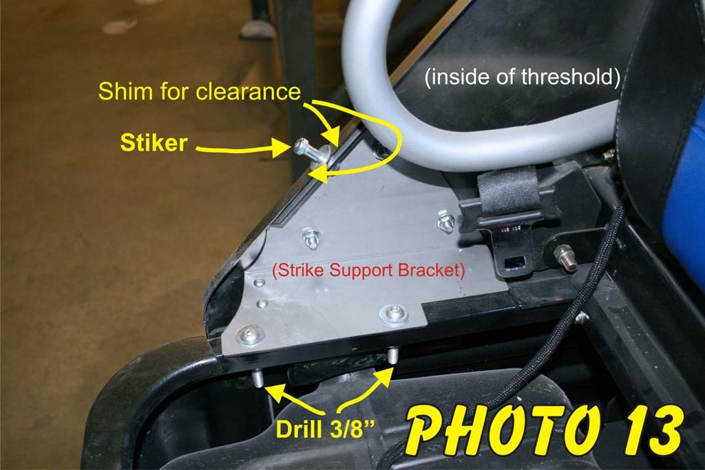
5 NOTE: Hinge brackets are slotted and may need to be adjusted in or out after the door is installed. If your windshield only has 1 mounting hole, you will need to drill a 3/8 hole after securing the existing hole. Drill the hole at the same location with in the hinge slot to allow for adjustment. 9. Align the lower flush fit seams (beside the front seat) and loosely fasten the inside horizontal flanges (below the seat belt) and vertical flanges (top and bottom) using ¼ x 1 button head bolts, 5/16 flat washers (inside and outside) and nylock nuts. 10. Align the front and rear thresholds to provide an even overlapping seam. Secure by tightening the overlap fasteners, hinge pin receivers, and center mount bracket Photo 11. NOTE: Align the hinge pin receivers and the limiter bracket vertically before tightening. Align and secure the lower seams. 11. FRONT AND REAR. Loosely fasten the filler panel to the bottom of the striker support bracket using the ¼ x ½ button head bolts and flange nuts Photo 1. With the seat removed, align the striker support bracket with the threshold and install the striker bolt (washer outside), and (3) 5/16 x 5/8 button head bolts and flange nuts. Tighten the striker first. Align the slots in the bracket over the seat support and drill 3/8 holes thru the CENTER of the seat support (you should use an angle head drill). Fasten loosely using 3/8 x 1 ¾ button head bolts, washers (top), and flange nuts Photo FRONT AND REAR. Adjust the threshold to provide as flat of a surface as possible for the door to close against. First push the bottom of the threshold tight against the frame and tighten the 4 floor screws. Next hold the clamps and threshold parallel to the door opening and tighten. Push the door threshold and strike support bracket in or out to align and tighten in place. Position the filler panel tight against the plastic side panel and tighten. 13. Install the kick panels omitting the outside screws. Retain the screws for future use should the door threshold ever be removed. 14. Use the OEM screws and clips and fasten the rear seat kick panel to the rear threshold. (Clips shown in Photo 5)
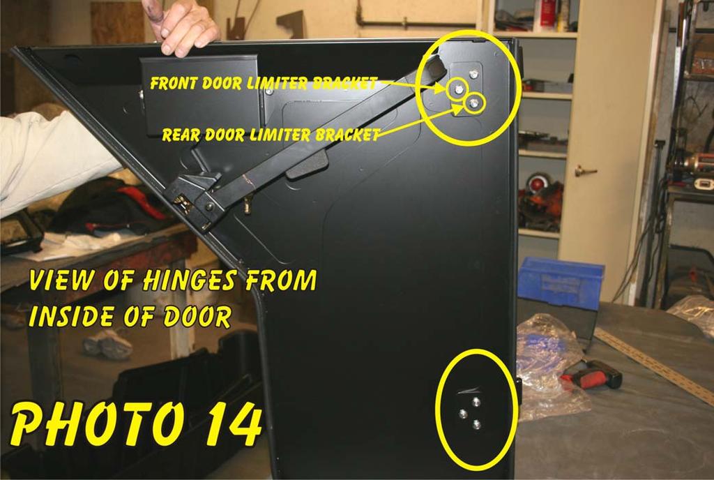
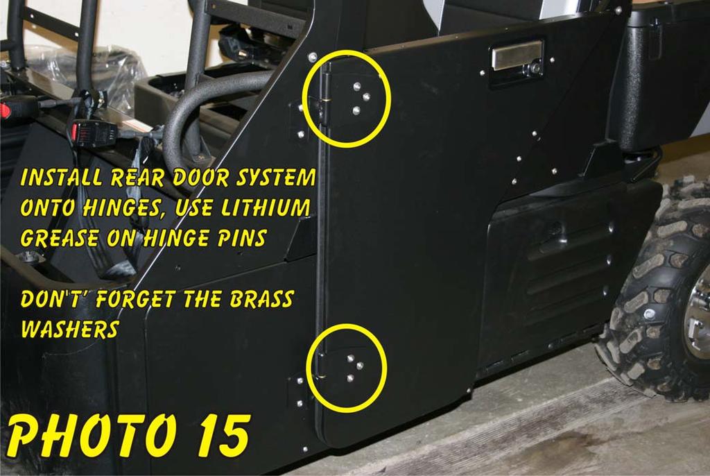
6 Installing and Adjusting Doors Front and Rear Refer to Photos 14 and 15 NOTE: Before making any adjustments regarding the seal or operation of the latch, the door must be hung and adjusted on the hinges with the proper alignment of the latch and striker, along with the proper clearance (1/8 ) between the plastic latch covers and the threshold. 1. Loosely install the hinges (pin down) to the outside of the lower half of the door using the ¼ x ¾ button head bolts, stainless steel washers (outside) backing plates then flange nuts on the inside. Install the door limiter bracket under the nut on the top hinge, center bolt on front doors, bottom bolt on rear doors. The doors and hinges are slotted for adjustment and must not be tightened at this time. 2. Set the Brass Washers on the hinge pins (Works well to super glue them on to prevent future loss.) and hang the door on the hinge bracket. Slowly attempt to close the door and adjust on the loose hinges to align the latch with the striker bolt. The latch should be centered or slightly high (to compensate for the weight of the upper half of the door) on the striker bolt. Allow 3/16 clearance between the plastic latch cover and the threshold. Using a 3/16 shim taped to the threshold on both sides of the striker bolt may help to maintain this clearance. Make sure the hinges are bottomed out against the hinge bracket and tighten securely. Slowly close the door several times to check for proper latch alignment and clearance. Adjust if necessary. Minor adjustments may be made to the latch after the top half of the door is installed. 3. Attach the top half of the door to the bottom using ¼ x ¾ hex head bolts with a lock then a flat washer on each bolt. The 2 inside bolts require flange nuts inside the armrest, the other have threaded weld nuts in place. Start all bolts first, and then tighten securely. ((Make sure outside of the door halves are lined up before tightening.))
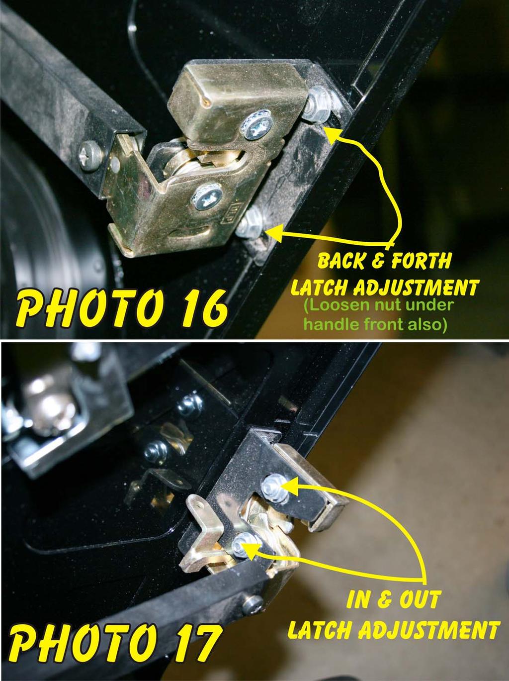
7 Final Adjustment Note: When properly fit and adjusted, the door should close smoothly by use of the inside grab handle or a firm pressure in the latch area (just below the handle) from the outside. The bulb seal should contact the threshold with only a slight compression. The latch is a double latch and must be in the second catch position for proper seal. Closing the door slowly you should be able to hear and feel the second catch in the latch. Front and Rear Refer to Photos 16 and Slowly try the door several times to check the alignment of the latch and the striker along with clearance of the plastic latch cover. If needed, loosen the hinges bolts and adjust. 2. The hinge bracket on the Front door only may be moved in or out to adjust the seal on the front edge of the door. Loosen the 4 nuts securing the bracket and adjust the top or bottom as needed. Too much compression of the bulb seal on the front portion of the door will cause a binding effect. 3. The striker support bracket may be moved in or out to adjust the seal at the rear of the door. Loosen the 2 bolts securing the bracket to the seat support and adjust as needed. Moving the striker may effect the operation of the latch and the pressure needed to close the door. The latch may need to be adjusted to compensate for the seal adjustments ((see next step)). 4. The latch has 2 adjustments. It may be moved in or out to adjust the compression of the bulb seal and the amount of force necessary to close the door. It can also be moved from front to back to adjust the latch clearance. To adjust the latch, remove the retaining screw and the plastic latch cover. On the end of the latch are 2 screws which hold the latch to the bracket. Loosening these screws will allow you to move the latch in or out from the striker. To move the latch front to back, you will need to remove the plastic cover on the front of the inside handle with a screwdriver and loosen the nut. Loosen the nuts under the latch which secure the bracket to the door. Make sure the retaining screw for the latch cover is in place and move the handle and latch as needed 5. Install the limiter strap using the quick release pin on the threshold and the ¼ x 1 ½ button head bolt and nylock nut on the door mounted bracket.
8 At this point your door installation should be complete. Double check all fasteners, reinstall your seat and take it for a test ride. You earned it! Note: After several hours of use with the new doors installed, it is recommended to go through the steps of the installation and tighten and or readjust and align as needed. Please make your customer aware that future adjustment may be needed as all these components are breaking in. We recommend that all installation manuals are packaged with any other owner s manuals that are shared with the customer upon purchasing any of our products.
9
10
11
12
13
14
15
16
17

18 Your RangerWare product can be registered at: If you have questions during your install our technical department can be contacted at or River Road Grand Rapids, MN 55744
INSTALLATION INSTRUCTIONS RH 412 STEEL DOORS
 By following the steps outlined below, the assembly, installation and adjustment of the steel doors, will be a simple process. Let s start with the Driver Side. Note: Having the hood open makes the job
Installation for Full Size Polaris Ranger Crew Doors
 Installation for Full Size Polaris Ranger Crew Doors Order of Installation: Heater Doors Wiper on to Windshield Windshield Top & Back Panel Note: Most of the steps in these instructions need to be repeated
RH-412 STEEL DOORS INSTALLATION INSTRUCTIONS
 RH-412 STEEL DOORS INSTALLATION INSTRUCTIONS By following the steps outlined below, the assembly, installation and adjustment of the steel doors, will be a simple process. Let s start with the Driver Side.
RangerWare Fiberglass Door System Installation Instructions P/N
 Page 1 of 9 RangerWare Fiberglass Door System Installation Instructions P/N 2878016 ORDER OF INSTALLATION Note: To assure proper order, read all Accessory Installation Instructions before beginning. 1.
INSTALLATION INSTRUCTIONS
 NOTE: Bolts should remain hand tight until all bolts are installed. STEP 1 Installing the door base (both sides). 1. Locate the outer, roll cage, mounting bolt (passenger side is shown in the illustration).
Assembly Instructions 10 X 10 Aluminum Frame Building
 Assembly Instructions 10 X 10 Aluminum Frame Building 27 97 9 8 47 36 74 52 10 10 X 10 Square Building W/ Dome Includes: The Steel Entry Door with a Dead Bolt Lock assembly and Aluminum Door Frame. Metal
Assembly Instructions 10 X 10 Aluminum Roof Support
 Assembly Instructions 10 X 10 Aluminum Roof Support Aluminum Roof Support Bolt Package 16-5/16 X 2 ¼ SS Bolt 24-5/16 X 1 SS Bolt 40-5/16 SS Nylon Lock Nuts 16-5/16 SS Flat Washers 28-4 ½ Wood Screws 36-1
INSTALLATION INSTRUCTIONS KK-K9-C12-K CHEVY IMPALA
 INSTALLATION INSTRUCTIONS KK-K9-C12-K 2000-2005 CHEVY IMPALA READ ALL INSTRUCTIONS PRIOR TO INSTALLATION TOOLS REQUIRED: Power Drill Drill bits1/4 and 5/32 7/l6 wrench and socket 15,18 and\or 19mm socket
KWIK-KIT KK-S INSTALLATION INSTRUCTION PACKAGE
 KWIK-KIT KK-S-120-02 INSTALLATION INSTRUCTION PACKAGE INSTALLATION INSTRUCTIONS HAVIS KWIK-KIT KK-S-120-02 2002-2007 DODGE/FREIGHTLINER SPRINTER VAN PLEASE READ COMPLETE INSTRUCTIONS PRIOR TO INSTALLATION
K9 KIT INSTALLATION INSTRUCTIONS CROWN VIC KK-K9-F7-K
 K9 KIT INSTALLATION INSTRUCTIONS 1998-2011 CROWN VIC KK-K9-F7-K TOOLS REQUIRED: Power Drill (Cordless preferable) Drill Bit Set Standard Wrench and Socket Set Metric Socket Set Screwdriver Set Torx Bit
Kawasaki Teryx 750 Cab Kit* Caution: Before using this product, read this manual and follow all Safety Instructions.
 Owner s Manual Model: Kawasaki Teryx 750 Kawasaki Teryx 750 Cab Kit* Caution: Before using this product, read this manual and follow all Safety Instructions. Safety Instructions Cab Kit Contents Hardware
Mid Size Ranger Pro-fit Doors #06023 Installation & Operations Manual
 Mid Size Ranger Pro-fit Doors #06023 Installation & Operations Manual Before You Start: Please familiarize yourself with all the steps before beginning assembly. Compatibility Info: This Door System is
General Prisoner Transport Install Instructions PT-2-INST
 General Prisoner Transport Install Instructions PT-2-INST 50 or 60 high x 80, 100 & 120 inch long / Double Compartment Inserts Also refer to PT-A-3XX instructions for vehicle specific mounting measurements
Polaris General Doors #06016 Installation & Operations Manual Fits Polaris General
 Polaris General Doors #06016 Installation & Operations Manual Fits Polaris General Before You Start: Please familiarize yourself with all the steps before beginning assembly. Compatibility Info: This Door
INSTALLATION INSTRUCTIONS GRILLE GUARD 09-ON DODGE RAM PART #
 INSTALLATION INSTRUCTIONS GRILLE GUARD 09-ON DODGE RAM PART # PARTS LIST: Qty Description Qty Description 1 Grille Guard 8 12-1.75mm x 35mm Hex Bolts 2 Brackets (for trucks without 22 12mm x 30.1mm OD
K9 KIT INSTALLATION INSTRUCTIONS CROWN VIC with Fire Suppression System Model KK-K9-F7-K-FS
 K9 KIT INSTALLATION INSTRUCTIONS 2005-2011 CROWN VIC with Fire Suppression System Model KK-K9-F7-K-FS TOOLS REQUIRED: Power Drill (Cordless preferable) Drill Bit Set Standard Wrench and Socket Set Metric
INSTALLATION INSTRUCTIONS KK-K9-F14-K K9 KIT FOR FORD EXPEDITION
 INSTALLATION INSTRUCTIONS KK-K9-F14-K-32 32 K9 KIT FOR 2003-2016 FORD EXPEDITION TOOLS REQUIRED: Power Drill Drill Bit Set Standard & Metric Socket Sets Phillips Screw Driver Open End Wrench Set Wire Cutters
INSTALLATION INSTRUCTIONS 3"/4 BENT END SIDEBARS FORD F-150 SUPERCREW PART # DZ /DZ
 INSTALLATION INSTRUCTIONS 09-12 FORD F-150 SUPERCREW PART # DZ 372697/DZ 372699 PARTS LIST: 1 Driver/Left Sidebar 4 1/2 Lock Washers 1 Sidebar 4 12mm x 32mm OD x 3mm Flat Washers 1 Driver/Left Mounting
D. Drill Bolt Holes Through Topper Shell and Bed Rails
 A. Check Mounting Kit Check to make sure that all of the following items are included in the mounting kit. Call 515-272-4372 if you need to obtain a part from BrandFX. Double-stick tape (1 roll) White
DOOR KIT P/N APPLICATION BEFORE YOU BEGIN KIT CONTENTS. Instr Rev Page 1 of 6. Verify accessory fitment at Polaris.com.
 DOOR KIT P/N 2882528 APPLICATION Verify accessory fitment at Polaris.com. BEFORE YOU BEGIN Read these instructions and check to be sure all parts and tools are accounted for. Please retain these installation
Introduction. Rocky Mountain Westy Swing Away Carrier Kit Installation Instructions
 Rocky Mountain Westy Swing Away Carrier Kit Installation Instructions Introduction Thank you for purchasing the Rocky Mountain Westy Swing Away Carrier Kit. We pride ourselves in the products we develop
Before returning this product to the store of purchase
 Before returning this product to the store of purchase Contact Dee Zee if you experience the following problems: Missing Parts Installation Problems/Questions Warranty Questions 1.800.779.2102 Hours of
TOOL LIST FOR TAILGATE HIDDEN LATCH & LINK ASSY FOR FORD FLARESIDE TRUCKS
 TOOL LIST FOR TAILGATE HIDDEN LATCH & LINK ASSY FOR 53-87 FORD FLARESIDE TRUCKS Vise Grip Clamps C-clamps Sharpie Marker Ball Peen Hammer Center Punch 3/8 or 1/2 Drill 5/32, 7/32, 9/32, and 3/8 Drill Bits
INSTALLATION & OWNER S MANUAL
 Rev. O p. 1 of 16 INSTALLATION & OWNER S MANUAL V4213 BALL CAGE KIT INSTALLATION & OWNER S MANUAL The contents of this envelope are the property of the owner. Be sure to leave with the owner when installation
Assembly Instructions
 Unite Panel System Hinge Door July 2016 #12 x / slotted hex washer head bolt Figure 1 threshold bracket frame Detail F threshold bracket threshold bracket (installed) #12 x / slotted hex washer head bolt
Polaris XP Doors (P144202) Installation Instructions
 Installation Instructions") Polaris XP4 000 Doors (P440) Installation Instructions WARNING Pro Armor Door and Net are designed to work together to replace your original equipment nets and/or door. Install both the Pro Armor Door
Polaris XP4 000 Doors (P440) Installation Instructions WARNING Pro Armor Door and Net are designed to work together to replace your original equipment nets and/or door. Install both the Pro Armor Door
Intercooler Shroud and Belt Cover for WRX
 Intercooler Shroud and Belt Cover for 2015+ WRX 2016-05-18 Thank you for purchasing this PERRIN product for your car! Installation of this product should only be performed by persons experienced with installation
MM Strut Tower Brace, Cobra (MMSTB-7)
") The MM strut Tower Brace attaches to each strut tower and to the firewall. 3430 Sacramento Dr., Unit D San Luis Obispo, CA 93401 Telephone: 805/544-8748 Fax: 805/544-8645 www.maximummotorsports.com MM
The MM strut Tower Brace attaches to each strut tower and to the firewall. 3430 Sacramento Dr., Unit D San Luis Obispo, CA 93401 Telephone: 805/544-8748 Fax: 805/544-8645 www.maximummotorsports.com MM
INSTALLATION INSTRUCTIONS FOR FRONT CASTING DECK RAIL Ranger
 INSTALLATION INSTRUCTIONS FOR FRONT CASTING DECK RAIL Ranger TOOLS REQUIRED FOR INSTALLATION: Drill motor, (1) 5/16 inch drill bit, (1) 13/64 drill bit, (1) 3/16 inch hex wrench (1) 3/32 inch hex wrench.
1. Begin by rolling your window up all the way 2. Remove your door and window handles by unscrewing the flat head set screws behind each handle.
 1. Begin by rolling your window up all the way 2. Remove your door and window handles by unscrewing the flat head set screws behind each handle. 3. Remove the 12 screws that attach the steel interior door
INSTALLATION INSTRUCTIONS GRILLE GUARD RAM 1500 PART # 5058/5058-2
 INSTALLATION INSTRUCTIONS GRILLE GUARD PART # 5058/5058-2 PARTS LIST: Qty Description Qty Description 1 Grille Guard 8 12-1.75mm x 35mm Hex Bolts 2 Upper Frame Mounting s (for trucks without tow hooks
RAMPAGE P R O D U C T S. INSTALLATION INSTRUCTIONS BRONCO ZIPPER FASTRACK TOP PART #984xx BRONCO TOOLS REQUIRED
 RAMPAGE P R O D U C T S 84 (+/- 1/4 ) INSTALLATION INSTRUCTIONS BRONCO ZIPPER FASTRACK TOP PART #984xx BRONCO 1966-1977 TOOLS REQUIRED 3/8 WRENCH 7/16 WRENCH ½ WRENCH #2 PHILLIPS SCREWDRIVER 1/8 DRILL
ED1300/1300F SERIES CONCEALED VERTICAL ROD DEVICE INSTALLATION INSTRUCTIONS
 ED1300/1300F SERIES CONCEALED VERTICAL ROD DEVICE INSTALLATION INSTRUCTIONS Ver.2 1300 SERIES CONCEALED VERTICAL ROD DEVICE Top Strike Latch Screws Strike Screws Release Plunger Top Latch Plunger Screws
TOOLS REQUIRED Metal Wood Wood and Metal Screws. #16 Drill #12-24 Tap. 1/8 Drill
 DEVICES COVERED IN THIS DOCUMENT: 4700S Surface Vertical Rod Device 4700SF Fire Exit Surface Vertical Rod Device TOOLS REQUIRED Metal Wood Wood and Metal Screws Sex Bolts #7 Drill ¼ -20 Tap #16 Drill #12-24
Privacy Wall Glass Selections - Polished Edge Slider Door
 Privacy Wall Glass Selections - Polished Edge Slider Door 3/6" HEX BIT PUTTY KNIFE #2 ACR BIT SUCTION CUP HOLDERS DOOR LEAF: Satin Tempered Clear Tempered LOCTITE 425 SIDE LIGHT ETCHED GLASS STYLES: Satin
Installation Instructions
 CHEVY / GMC 20K Industry Standard Rail Custom Mounting Kit #2724 Gross Trailer Weight (Maximum)...20,000 lbs. Vertical Load Weight (Max. Pin Weight)...5,000 lbs. SYSTEM TOW CAPACITY Please note, in order
ESA-200 Fixed Sidelite
 Exterior View Installation Instructions For use with ESA II Controller 1 Tools Required: Suggested Fasteners Required - (Not supplied) Screwdrivers Small Straight (FlatBlade) - for Terminal Block wiring
MM Strut Tower Brace, GT (MMSTB-5.1)
") 3430 Sacramento Dr., Unit D San Luis Obispo, CA 93401 Telephone: 805/544-8748 Fax: 805/544-8645 www.maximummotorsports.com MM Strut Tower Brace, 1996-97 GT (MMSTB-5.1) MMSTB-5.1 is for 1996-97 GT s with
3430 Sacramento Dr., Unit D San Luis Obispo, CA 93401 Telephone: 805/544-8748 Fax: 805/544-8645 www.maximummotorsports.com MM Strut Tower Brace, 1996-97 GT (MMSTB-5.1) MMSTB-5.1 is for 1996-97 GT s with
YJ Bow Assembly. Installation Instructions INSTALLATION TIME SKILL LEVEL TOOLS. Vehicle Application: Jeep Wrangler YJ Part Number: 55004
 Installation Instructions YJ Bow Assembly Vehicle Application: Jeep Wrangler YJ 1988 1995 Part Number: 55004 INSTALLATION TIME SKILL LEVEL 2 Hours 2 - Moderately Easy TOOLS 1/8" Bit 10' #2 #50, #45, #50
Be sure any accessory used will fit with the soft upper doors before installing. Not all accessories will be compatible.
 Company Name: Spike Power Sports Vehicle Name: Polaris General 2P Product Description: Soft Upper Doors Part Number: 58-1600 Revision: R01 09/19/2018 Contents: 655 Elm Ridge Ave, Canal Fulton OH, 44614
Installation Instructions
 FORD 20K Industry Standard Rail Custom Mounting Kit #2738 Gross Trailer Weight (Maximum)...20,000 lbs. Vertical Load Weight (Max. Pin Weight)...5,000 lbs. SYSTEM TOW CAPACITY Please note, in order to determine
INSTALLATION INSTRUCTIONS DODGE RAM 2 & 4WD 1500 PART # P5058
 INSTALLATION INSTRUCTIONS 2009-13 DODGE RAM 2 & 4WD 1500 PART # P5058 PARTS LIST: Qty Description Qty Description 1 Grille Guard 12 12-1.75mm Hex Nuts 2 Upper Frame Mounting s (for trucks without tow hooks
ASSEMBLY INSTRUCTIONS FOR MAR-K BEDSIDES AND GM FLUSH TAILGATE WITH HANDLE
 ASSEMBLY INSTRUCTIONS FOR MAR-K BEDSIDES AND 41-53 GM FLUSH TAILGATE WITH HANDLE Build the box assembly according to the MAR-K assembly instructions. When installing the tailgate and latching mechanisms
Kawasaki Mule Pro Upper Doors #06020 Installation & Operations Manual
 Kawasaki Mule Pro Upper Doors #06020 Installation & Operations Manual Before You Start: Please familiarize yourself with all the steps before beginning assembly. Compatibility Info: This Door System is
Driver/Left Top. Support Bracket
 PARTS LIST: 1 Grille Guard 8 10mm Lock Washers 1 Driver/Left Frame Bracket 8 10mm Hex Nuts 1 Passenger/Right Frame Bracket 2 8-1.25mm x 25mm Button Head Bolts 1 Driver/Left Bottom Support Bracket 2 8mm
INSTALLATION INSTRUCTIONS
 INSTALLATION INSTRUCTIONS TOOLS REQUIRED Rechargeable, variable speed drill 3/8 diameter drill bit 3 Robertson bits #0, #1 and #2 Slot screwdriver Non marring hammer with 1 head Level Caulk or sealant
Oxford Stalls Installation Instructions
 Oxford Stalls Installation Instructions RAMM Horse Fencing and Stalls 13150 Airport Hwy. Swanton, OH 43558-9615 1-800-434-8456 Rev. 8/15/17 Before You Start Typical stall sizes are 10 x 10, 12 x 12 or
Full Size Ranger Pro-fit Doors #06015 Installation & Operations Manual
 Full Size Ranger Pro-fit Doors #06015 Installation & Operations Manual Before You Start: Please familiarize yourself with all the steps before beginning assembly. Compatibility Info: This Door System is
Roll In W/L Dock PAGE 1
 Roll In W/L Dock PAGE 1 1 2 3/8 X 1 CARRIAGE BOLT SS 3/8 FLANGE NUT BRASS 3 4 1/2-13 X 1.25 SQ BOLT SS 1/2 SQ NUT BRASS 5 3/8-16 X 2.5" BOLT SS PAGE 2 6 7 BRACE BRKT SINGLE AXLE TUBE 8 9 3" AXLE WASHER
INSTALL INSTRUCTIONS KK & KK KWIK-KIT PRISONER TRANSPORT INSERT FORD and CHEVY VAN PRISONER TRANSPORT
 INSTALL INSTRUCTIONS KK-100-03 & KK-120-03 KWIK-KIT PRISONER TRANSPORT INSERT FORD and CHEVY VAN PRISONER TRANSPORT TOOLS REQUIRED: ¼ & 3/8 Ratcheting Wrenches ¼ & 3/8 Air Ratchets (recommended) 3/8 Impact
INSTALL INSTRUCTIONS
 Jeep JK Rear Stealth Bumper Product : 508R0B, 508R0B TC Applica on : 2007+ Jeep Wrangler JK ( 2 Door and 4 Door ) Page ( 1 of 5 ) I WARNING Read the instruc ons completely before beginning installa on.
INSTALL INSTRUCTIONS K9-F14-PT K9/PRISONER TRANSPORTATION SYSTEM FORD EXPEDITION
 INSTALL INSTRUCTIONS K9-F14-PT K9/PRISONER TRANSPORTATION SYSTEM 2003-2017 FORD EXPEDITION HARDWARE: QTY: DESCRIPTION: PART #: 28 ¼-20 x ½ Stainless carriage bolt GSM32022 8 ¼-20 x ¾ Stainless carriage
NISSAN NV200 CHEVY CITY EXPRESS WALL LINER KIT INSTALLATION INSTRUCTIONS
 NISSAN NV200 CHEVY CITY EXPRESS WALL LINER KIT INSTALLATION INSTRUCTIONS NOTES: 1. Before commencing, remove all wall liners and D Rings already installed in the vehicle. 2. Consult layout PDF and compare
Series 1500 Aluminum Door Canopy
 Series 500 Aluminum Door Canopy with Sidewings It is our recommendation that you read instructions carefully prior to assembly and installation. Series 500 with Sidewings mounting bar (A) top trim (B)
6000 Horizontal Router Table Owners Manual Please Read Carefully!
 6 Horizontal Router Table Owners Manual Please Read Carefully! Parts List Please identify and verify that you have all of the hardware & parts shown prior to assembly. The parts described in this box are
ESA-300 Full Breakout
 Interior View 0 Installation Instructions For use with ESA II Controler DORMA AUTOMATICS, Inc. 94 Sherwood Drive Toll-Free: 877-67-6 DL844-00 Lake Bluff, IL 60044 Fax: 877-4-7999 Rev. /07 Tools Required:
INSTALLATION INSTRUCTIONS
 INSTALLATION INSTRUCTIONS Accessory FABRIC REAR DOORS (5P) P/N 0SR90-HL4-211B (BLACK) P/N 0SR90-HL4-211C (CAMO) Application SXS1000M5P/M5D Honda Dealer: Please give a copy of these instructions to your
VIEWPOINT ALUMINUM RUNNING BOARD TOYOTA RAV4
 PARTS LIST: VIEWPOINT ALUMINUM RUNNING BOARD 1 Driver/Left Running Board 4 10-1.5mm x 50mm T-Bolt 1 Passenger/Right Running Board 12 10mm Plastic Retainers 1 Driver/Left Bracket 2 10-1.50mm x 40mm Hex
WARNING Indicates a hazardous situation which, if not avoided, could result in death or serious injury. WARNING. Ranger XP Door Kit
 REVISION 04 November, 20 2018 Ranger XP Door Kit Prior to installation, please verify if a revised version of this instruction sheet is available on Knowledge Center. The following symbols may be used
a.k.a. casegoods instructions
 a.k.a. casegoods instructions a a.k.a. workwall installation IMPORTANT NOTES Failure to install product according to installation instruction will result in loss of warranty. Tools required for assembly
INSTALLATION INSTRUCTIONS 3 BULL BAR 99-04, 04 "HERITAGE" F-150/250LD 2WD, 97-04, 04 "HERITAGE" 4WD WD EXPEDITION/ WD EXPEDITION PART
 INSTALLATION INSTRUCTIONS 3 BULL BAR PART #B-F1971;B-F2971 PARTS LIST: 1 Bull Bar 2 12-1.75mm x 130mm x 40mm Hex Bolts 1 Driver/Left Mounting Bracket 4 12-1.75mm x 35mm Hex Bolts 1 Passenger/Right Mounting
LANDING GEAR. 1. Fit landing gear into slots on bottom of fuselage.
 LANDING GEAR 1. Fit landing gear into slots on bottom of fuselage. 4. Use channel-lock pliers to press blind nuts into position (note: drilled hole should be slightly smaller than shaft of blind nut for
JK Front Crusher Flares
 INSTALLATION INSTRUCTIONS INST-17-03-030_A JK Front Crusher Flares IMPORTANT: Thank you for purchasing this Poison Spyder product. Please read through this entire document before proceeding with installation.
Please read BOTH these Installation Instructions and the General Instructions before attempting to install or operate this equipment.
 Please read BOTH these and the General Instructions before attempting to install or operate this equipment. 1. Blue Ox towing products and accessories are intended to be installed by Blue Ox Dealers who
GRILLE GUARD SPRINTER VAN (EXCLUDES X4) INCLUDES MERCEDES, FREIGHTLINER AND DODGE PARTS LIST:
 INCLUDES MERCEDES, FREIGHTLINER AND DODGE PARTS LIST:") PARTS LIST: 1 Grille Guard 8 12mm Hex Nuts 1 Driver/Left Side Frame Mounting Bracket 2 10-1.50mm x 25mm Button Head Bolts 1 Passenger/Right Side Frame Mounting Bracket 4 10mm x 20mm OD x 2mm Flat Washers
PARTS LIST: 1 Grille Guard 8 12mm Hex Nuts 1 Driver/Left Side Frame Mounting Bracket 2 10-1.50mm x 25mm Button Head Bolts 1 Passenger/Right Side Frame Mounting Bracket 4 10mm x 20mm OD x 2mm Flat Washers
FlexFrame - Storage Components and Skins
 FlexFrame - Storage Components and Skins 1/4 Square Drive Ball-Point Hex-Bit Socket 1/8 Short Hex, 1-1/2 Overall Length McMaster Part # 54075A44 Table of Contents Topic Page Storage Components 2 General
TIRE RACK INSTALLATION INSTRUCTIONS Dodge Sprinter
 Aluminess Products Inc 9402 Wheatlands Ct. #A Santee, CA 92071 619-449-9930 TIRE RACK INSTALLATION INSTRUCTIONS 07-11 Dodge Sprinter Please read before beginning Stainless steel hardware may bind together
For additional assistance call
 The following pages will help guide you through the process of assembling your new 48 custom prize wheel. Choose an assembly area with plenty of room to lay your pieces on the floor and also a bench or
JEEP JK ( 5 DOOR ) SLIMLINE II - FULL TRAY EXTREME RACK KIT
 SLIMLINE II - FULL TRAY EXTREME RACK KIT") JEEP JK ( 5 DOOR ) SLIMLINE II - FULL TRAY EXTREME RACK KIT FAJK001 / KRJW014T INSTALL TIME: 2.5 Hours NOTE: Your Jeep JK (5 Door) Extreme Roof Rack Kit consists of four boxes. (1) the Tray, (2) the Roll
JEEP JK ( 5 DOOR ) SLIMLINE II - FULL TRAY EXTREME RACK KIT FAJK001 / KRJW014T INSTALL TIME: 2.5 Hours NOTE: Your Jeep JK (5 Door) Extreme Roof Rack Kit consists of four boxes. (1) the Tray, (2) the Roll
======================================================================================== ( DR / DR) JK WRANGLER MOD RACK
 JK WRANGLER MOD RACK") (10984 4DR / 10982 2DR) JK WRANGLER MOD RACK INSTALLATION SHEET Important Notes: Some brands of windshield light brackets and snorkels may not be compatible with the 10984 MOD Rack System. Body lifts are
(10984 4DR / 10982 2DR) JK WRANGLER MOD RACK INSTALLATION SHEET Important Notes: Some brands of windshield light brackets and snorkels may not be compatible with the 10984 MOD Rack System. Body lifts are
GlideRite Retractable Cover System For HotSpring & Tiger River Spas (except Classic & pre-2000 Landmark Spas)
") List of Contents Quantity Description 12 #10 x 1 ½ Flat Head Phillips Screw (see pg. 2) 2 #10 x ½ Pan Head Phillips Screw (see pg. 2) 8 ¼ x 2 ½ Lag Bolt (see pg. 2) 7 ¼ 20 x 5 / 8 Hex Head Bolt (see pg.
List of Contents Quantity Description 12 #10 x 1 ½ Flat Head Phillips Screw (see pg. 2) 2 #10 x ½ Pan Head Phillips Screw (see pg. 2) 8 ¼ x 2 ½ Lag Bolt (see pg. 2) 7 ¼ 20 x 5 / 8 Hex Head Bolt (see pg.
ESA-100 Fixed Sidelite/Non Breakout
 /Non Breakout Exterior View Installation Instructions For use with ESA II Controller 1 Tools Required: Suggested Fasteners Required - (Not supplied) Screwdrivers Small Straight (FlatBlade) - for Terminal
Installation Manual for Metal Toilet Partitions Standard Series
 For Video instructions http://www.hadrian-inc.com/tech-data/installation/toilet-partitions.aspx P a g e 1 Table of Contents Page General Notes and Tools Required 3 STEP 1: Establish Floor Bracket Locations
Master Your Terrain. (307)
") Master Your Terrain (307) 775 9565 www.tntcustoms.com Rear Swing-out Tire Carrier Jeep TJ/LJ Installation Instructions Congratulations for purchasing a T&T Customs, Inc. Rear Swing-out Tire Carrier for
Master Your Terrain (307) 775 9565 www.tntcustoms.com Rear Swing-out Tire Carrier Jeep TJ/LJ Installation Instructions Congratulations for purchasing a T&T Customs, Inc. Rear Swing-out Tire Carrier for
INSTALLATION GUIDE 2009-CURRENT HUMMER H3T PRODUCT CODE:
 INSTALLATION GUIDE 2009-CURRENT HUMMER H3T PRODUCT CODE: 268 June 22, 2010 TOOLS NEEDED COMPONENTS INCLUDED P2 Tip 3/8" Drill Rubber Gasket(s) x 2 Bracket(s) x 2 1/2" Drill Bit Bulkhead Flange #2 Phillips
EmagiKit. Privacy Pod Plus. Quiet. Easy. Affordable. INSTRUCTIONS ASSEMBLY
 EmagiKit Privacy Pod Plus Quiet. Easy. Affordable. INSTRUCTIONS ASSEMBLY DIMENSIONS AND COMPONENTS 47 47 Ceiling Unit 2-B 2-L 2-R Glass Door Corner Trim Door Handle 90 Adjustable Height Work Surface 1-B
Model 209 Fireback Replacement
 Model 209 Fireback Replacement Please read all the instructions before you begin the procedure. Confirm that you have all the necessary tools and materials. If you have any questions, technical support
33/3527A. Devices covered by these instructions: 33/3527A-F (Fire) Surface Vertical Rod Exit Device
 Surface Vertical Rod Exit Device") *911403-00* 911403-00 Surface Vertical Rod Exit Device 33/3527A Installation Instructions Devices covered by these instructions: 33/3527A Surface Vertical Rod Exit Device 33/3527A-F (Fire) Surface Vertical
*911403-00* 911403-00 Surface Vertical Rod Exit Device 33/3527A Installation Instructions Devices covered by these instructions: 33/3527A Surface Vertical Rod Exit Device 33/3527A-F (Fire) Surface Vertical
Shetland Stalls Installation Instructions
 Shetland Stalls Installation Instructions RAMM Horse Fencing and Stalls 13150 Airport Hwy. Swanton, OH 43558-9615 1-800-434-8456 Rev. 1/9/18 Before you start Kit can accommodate up to 12 wide stall front
IMPORTANT: PLEASE RETAIN THIS INSTRUCTION MANUAL FOR FUTURE REFERENCE
 IMPORTANT: PLEASE RETAIN THIS INSTRUCTION MANUAL FOR FUTURE REFERENCE 005-07 Cadillac STS Classic 3D Z, Classic Dual Weave, Classic Mesh & Classic Black Mesh Grilles B 7 HR 3 STS Classic 3D Z Grille Part
Tech Sheet. T4 Interior conversion kit how to - fitting instructions. 1. Rear seat belts. 2.
 Page 1 of 8 T4 Interior conversion kit how to - fitting instructions Thank you for purchasing our T4 interior conversion kit. This kit will enable you to convert any SWB left hand loading door T4 into
Parts and tools needed for installation- Cleaning and Painting -
 Thank you for the purchase of our JK Rear Trail Doors. We have made these from 6061-T6 aluminum and reinforced them with stiffeners at the top that double as a comfortable armrest and support for Rugged
Installation Instructions
 CHEVY / GMC 24K Industry Standard Rail Heavy Duty Custom Mounting Kit #2226 Gross Trailer Weight (Maximum)...24,000 lbs. Vertical Load Weight (Max. Pin Weight)...6,000 lbs. SYSTEM TOW CAPACITY Please note,
Series 1100 Aluminum Door Canopy
 Series 00 Aluminum Door Canopy with Support Arms It is our recommendation that you read instructions carefully prior to assembly and installation. Series 00 with Support Arms MOUNTING BAR (A) TOP TRIM
CHEVY/GMC SuperRail Mounting Kit #3117
 CHEVY/GMC SuperRail Mounting Kit #3117 #3100 SuperGlide (12K) Gross Trailer Weight (Maximum) Vertical Load Weight (Max. Pin Weight) 12,000 lbs. 3,000 lbs. Installation Instructions SPECIFICATIONS Fits
Gared Pro-S Portable Backstop
 Models: 9616 & 9618 Installation, Operation and Maintenance Instructions Please read all instructions before attempting installation or operation of these units SAVE THESE INSTRUCTIONS FOR FUTURE USE PUBLICATION
Quill Stop V2 Installation Guide 11/16/2014
 Thank you for purchasing the Quill Stop for the Sieg X3 (Grizzly G0463) and SX3 (Grizzly G0619) mills. Your feedback is always appreciated. Please email questions and comments to gregpriest@cox.net. What
Custom Wood Frame Overlay for Glass Doors Installation Instructions
 MARVEL CUSTOM WOOD FRAME OVERLAY FOR GLASS DOORS Custom Wood Frame Overlay for Glass Doors Installation Instructions Wine Cellars 6SWC 6SWCE 61WC 61WCM 66SWC (2 required) 66SWCE (2 required) Beverage Centers
INSTALLATION INSTRUCTIONS CJ-5 M38A PART # With Doors
 INSTALLATION INSTRUCTIONS CJ-5 M38A1 1955-1975 PART #109-011 With Doors Thank you for purchasing Specialty s Convertible Top for your Jeep vehicle. It has been designed for great fit and long wear. Please
Motorized or Crank Operated Fortress Zipper Track Shade with Housing and Side Track Installation Instructions
 Motorized or Crank Operated Fortress Zipper Track Shade with Housing and Side Track Installation Instructions Tools Needed Drill 3/8 Metal Drill Bit ¼ Masonry Drill Bit Measuring Tape Pencil 4 Level Phillips
Aluminum Sprinter Rack Installation
 INSTALLATION INSTRUCTIONS MyGlassTruck.com Division of Demountable Concepts, Inc Aluminum MyGlassTruck.Com Demountable Concepts, Inc. 200 Acorn Rd. Glassboro, NJ 08028 800.254.3643 toll free 856.863.0900
Installation Instructions
 CHEVY / GMC 20K Industry Standard Rail Custom Mounting Kit #2724 Gross Trailer Weight (Maximum)...20,000 lbs. Vertical Load Weight (Max. Pin Weight)...5,000 lbs. SYSTEM TOW CAPACITY Please note, in order
CHEVY/GMC SuperRail Mounting Kit #4423
 CHEVY/GMC SuperRail Mounting Kit #4423 #4100 SuperGlide (16K) #4400 SuperGlide (20K) Gross Trailer Weight (Maximum) Vertical Load Weight (Max. Pin Weight) 16,000 lbs. 4,000 lbs. Gross Trailer Weight (Maximum)
Installation Instructions
 FORD 20K Industry Standard Rail Custom Mounting Kit #2760 Gross Trailer Weight (Maximum)...20,000 lbs. Vertical Load Weight (Max. Pin Weight)...5,000 lbs. SYSTEM TOW CAPACITY Please note, in order to determine
Installation Instructions
 CHEVY / GMC 16K Industry Standard Rail Custom Mounting Kit #2730 Gross Trailer Weight (Maximum)...16,000 lbs. Vertical Load Weight (Max. Pin Weight)...4,000 lbs. SYSTEM TOW CAPACITY Please note, in order
INSTALLATION INSTRUCTIONS
 INSTALLATION INSTRUCTIONS HIGH PRESSUE LAMINATE (HPL) TOILET PARTITIONS 1030 TrimLineSeries 1040 DesignerSeries Includes continuous hardware option.65. IMPORTANT: Storage and Handling Information on last
Otter Pro XT Cottage Installation and Set-Up Instructions
 Otter Pro XT Cottage Installation and Set-Up Instructions Otter Pro XT Cottage Fits Small Ultra-Wide Otter Pro and Otter II Sled Only Parts Identification and Check List MODEL NUMBERS: Complete Pkg Pro
MobileTrak5 Installation Instructions
 MobileTrak5 Installation Instructions PLEASE OPEN ALL BOXES & CHECK TO MAKE SURE YOU HAVE ALL PIECES REQUIRED READ ALL INSTRUCTIONS BEFORE STARTING Tools Required for Assembly 7/16, 1/2 Wrench Phillips
INSTALLATION INSTRUCTIONS
 INSTALLATION INSTRUCTIONS SOLID PHENOLIC TOILET PARTITIONS 1080 DuraLineSeries Class-A Fire Rated Includes Institutional Hardware Option.67 IMPORTANT: Storage and Handling Information on last page. Review
Allow 60 from door face
 Setbacks Allow 60 from door face TOOLS NEEDED Tape Measure Marker or Pencil Masonry Drill Bit 3/8 Hammer Drill Hammer Socket Wrenches and Wrench: 9/16, 1/2, 7/16, 1/4 drive socket wrench and 1/2 socket