Hyperion System 9 Financial Data Quality Management
|
|
|
- Britton Stevens
- 5 years ago
- Views:
Transcription
1 Hyperion System 9 Financial Data Quality Management Administrator Training Guide WebLink Version 8.3, 8.31, and Hyperion System 9 Financial Data Quality Management Version Hyperion Financial Management (HFM) & Hyperion Enterprise
2 Hyperion Solutions Corporation. All rights reserved. Hyperion, the Hyperion logo and Hyperion s product names are trademarks of Hyperion. No portion hereof may be reproduced or distributed in any form or by any means, electronic or mechanical, including photocopying, recording, or information storage and retrieval systems, for any purpose other than the licensee s personal use, without the express written permission of Hyperion. This software is licensed according to the conditions set forth in your Hyperion software license agreement. Hyperion, LedgerLink, Hyperion Enterprise, and Essbase are registered trademarks of Hyperion Solutions Corporation. Hyperion Solutions, Hyperion Planning, and Hyperion Financial Management are trademarks of Hyperion Solutions Corporation. Citrix is a registered trademark of Citrix Systems Inc. Microsoft and Windows are registered trademarks of Microsoft Corporation in the United States and/or other countries. Oracle is a registered trademark of Oracle Corporation and/or its affiliates.
3 Table of Contents How to Use this Guide... v Organization... v Instructor Demonstrations... vi Walkthroughs... vi Exercises... vi Section A Hyperion FDM Basics Module 1: Overview of Hyperion FDM Introduction Definition of a Hyperion FDM Application Hyperion FDM Application Architecture Data Directory Inbox Directory Outbox Directory Reports Directory Managing Hyperion FDM Applications Opening Applications Creating Applications Removing Applications Adding Applications End User Process Module 2: Hyperion FDM Navigation Hyperion FDM Desktop Point of View (POV) POV Mode Local vs. Global Changing POV Mode Setting Location POV Setting Category POV Setting Period POV POV Search Locking and Unlocking the System How a User s Default Point-of-View is Determined Module 3: Building a Hyperion FDM Application Overview Introduction Pre-Implementation Data Requirements Section B: Building a Hyperion FDM Application Module 4: Creating a Hyperion FDM Application Overview a. Log onto Hyperion FDM Using the <New Application> Option b. Complete the New Application Dialog Box Module 5: Integrate with the Target Application Integration Overview a. Import the Target System Adaptor b. Register the Adaptor c. Add Machine Profile d. Verify Application Settings i
4 e. Update Integration Settings f. Update DCOM Settings g. Map Hyperion FDM Dimensions to Target Dimensions i. Test the Integration from within the Web Client Import the Standard Reports Import the Standard Templates Module 6: Populating Control Tables Control Tables Overview a. Open the Control Tables Screen b. Add the Periods c. Add the Categories d. Verify the Currency Codes Module 7: Setting Up Locations Hyperion FDM Locations Overview Hyperion FDM Location Types a. Open the Locations Screen b. Add New Location c. Apply Attributes to the New Location Module 8: Importing Mapping Tables Maps Overview a. Define Map Dimensions b. Set the Appropriate Dimension Labels c. Open the Maps Screen Map Types Building Maps in MapLoader d1. Import Maps d2. Copy Mapping Tables d3. Assign a Parent Map Additional Hyperion FDM Mapping Features and Information Conditional Mapping Module 9: Build Import Formats Overview of Import Formats a. Create a New Import Group b. Define Fields for the Import Group c. Assign Import Formats Advanced Import Expressions Sign 9-15 DRCRSplit = (Split Debit and Credit Columns) Fill = (Trailing Fill) Fill=EuroToUS FillL = (Leading Fill) Factor = (Value) NZP (No Zero Suppress) Expression Stacking and Processing Order Module 10: Test Data Loading Data Loading Overview a. Import Source File b. Validate the Mapping c. Export Mapped File to Target System ii
5 Section C Enhancing the Application Module 11: Validation Rules and Reports Validation Rules and Reports Overview a. Define Validation Rule Groups b. Define Validation Rules c. Attach Validation Rules to a Location d. Check Validation Rules Module 12: Validation Entities Overview a. Create Validation Entity Group b. Define Validation Entities c. Attach Validation Entity to a Location Section D Additional Functionality Module 13: Logic Accounts Overview Creating Logic Groups Logic Type Logic Group Security Simple Logic Accounts Assigning Function Return Values Hyperion FDM Lookup Function Creating Complex Logic Accounts Module 14: Journals Using a Journal Template Defining a Journal Template Metadata Structure Row 1 (Journal ID & Location Tag) Row 2 (Hyperion FDM Category Tag) Row 3 (Hyperion FDM Period Tag) Row 4 (Load Method Tag) Row 5 (Dimension Tags) Module 15: Multiload Definition of a Multiload File Text File Multiload vs. Excel Multiload Defining a Multiload Excel Template Metadata Tags Structure Process Summary Section E Hyperion FDM Administration Module 16: Key Tips and Navigation Sorting Records Finding Records Filtering Records Shortcut to Deleting All Records on the Import Screen Drilling Up Show Attributes Show Conversion Rules iii
6 Show Archive Information Open Source Document Open Processing Log Restore Source Document Drilling Down Drilling Up on a Drill-Down Searching Control Trees Module 17: Hyperion FDM Security Security Overview Levels of Security User Security Setting up User Security Deleting a User Changing Target System Password Modifying a User s Rights Object Maintenance Report Groups Security Module 18: Financial Controls Financial Controls Controls Groups Sections Questions Importing Questions from Excel Effective Date Recycle Bin Question Profiles Reviewers and Proxy Submitter and Proxy Risk Flag Level Process Explorer Adding Memos and Attaching Documentation Certification Process Answering Questions Application Settings Module 19: Map Converter Overview iv

7 How to Use this Guide Organization This manual is divided into five main sections: Hyperion FDM Basics, Building a Hyperion FDM Application, Enhancing Your Application, Additional Functionality, and Hyperion FDM Administration. Each of these sections is further divided into modules. Section A Hyperion FDM Basics Module 1: Overview of Hyperion FDM Module 2: Hyperion FDM Navigation Module 3: Building a Hyperion FDM Application Overview Section B Building a Hyperion FDM Application Module 4: Create a New Hyperion FDM Application Module 5: Integrate with Target Application Module 6: Populate Control Tables Module 7: Set up Locations Module 8: Build and/or Import Maps Module 9: Build Import Formats Module 10: Test Data Loading Section C Enhancing the Application Module 11: Validation Rules and Reports Module 12: Validation Entities Section D Additional Functionality Module 13: Logic Accounts Module 14: Journals Module 15: Multiload Section E Hyperion FDM Administration Module 16: Key Tips and Navigation Module 17: Hyperion FDM Security Module 18: Financial Controls Module 19: Map Converter This diagram illustrates the page format. All right-side pages include navigation information (current section number, module number, and page number). Section A Section B Section C Section D Section E
8 Hyperion FDM Administrator Training Guide Instructor Demonstrations The instructor will demonstrate a feature or function on the screen. Instructor demonstrations are written in a numbered format procedure, and can be identified by the icon to the left. Walkthroughs Walkthroughs are like instructor demonstrations in which the students also participate. The instructor and student work through a function or procedure simultaneously. Walkthroughs can be identified by the icon on the left. Exercises Exercises are identified by the pushup icon. Some exercises are specific to Hyperion Enterprise. Those are designated by the HE icon ( ). HFM-specific exercises are designated by the HFM icon ( ). Some exercises can be completed in either application, and will contain both icons. vi
9 Section A Hyperion FDM Basics In this Section: Module 1: Overview of Hyperion FDM Module 2: Hyperion FDM Navigation Module 3: Building a Hyperion FDM Application Overview
10
11 Module 1: Overview of Hyperion FDM
12
13 Module 1 Overview of Hyperion FDM Introduction Hyperion System 9 Financial Data Quality Management (Hyperion FDM) is an advanced Data Transformation Management (DTM) solution. Hyperion FDM provides a single, systematic process for loading source data from disparate systems into target analytical applications. The Hyperion FDM process provides data visibility, integrity, and verification. Hyperion FDM features and benefits include the following: Acting central repository of all source financial data Drill-down audit trail Ability to archive source files, error logs, and load files Internal controls assessment and certification feature aids in compliance with sections 302 and 404 of the Sarbanes-Oxley Act Corporate-wide process monitoring Ability to import source data from any formatted text file or data source Multiple dimension mapping and validating capability Data validation and quality checking Error identification and notification Consolidation of target system data Validation and reporting on target system data Load adjustments capability through Excel journals Budget data loading for multiple periods Advanced reporting and audit functions Lights out batch loading (requires batch loader license) Support for unlimited concurrent users Zero footprint Web deployment SQL & Oracle Database support Section A Section B Section C Section D Section E Hyperion FDM Basics 1-1

14 Hyperion FDM Administrator Training Guide Definition of a Hyperion FDM Application A Hyperion FDM application consists of a Relational Database Management System (RDBMS) database and directories that contain all the transactional data, metadata, reports, and other files that are used when integrating with an individual target system application. A new Hyperion FDM application is required for each target system application that Hyperion FDM will be loading. Valid target systems include Hyperion Enterprise, Hyperion Financial Management, Hyperion Financial Planning, Hyperion Essbase, and all other consolidation, reporting, planning, and analytical applications. There is no limit to the number of Hyperion FDM applications that can be created. Hyperion FDM Application Architecture A Hyperion FDM application contains a Data, Inbox, Outbox, and Reports directories. Figure 1-1 illustrates the directories and directory structure that are created when a new Hyperion FDM application is created. Figure 1 1: Hyperion FDM Application Data Structure The following topics provide more information about each of the folders in the application directory: Data Directory The Data directory contains a Scripts sub-directory where Hyperion FDM scripts are stored. The Data directory is also where Hyperion FDM archives all source files, journals, multiload files, logs, output data files, and attachments. 1-2
15 Module 1 Overview of Hyperion FDM Scripts Directory The Scripts directory is where all Hyperion FDM script files are stored and contains sub-directories for each type of script. Custom Directory contains script files that can be executed through a Hyperion FDM custom menu created in the Menu Maker form. Event Directory contains script files that are executed when a particular Hyperion FDM event executes. All scripts contained in this directory will be named for the event in which they correspond. Import Directory includes import scripts that are created when defining import formats. Import scripts are executed during the source file import process. Inbox Directory The Inbox directory is the default directory used by Hyperion FDM when importing a source file. Please note that it is not necessary to place the source file in this directory as Hyperion FDM can import source files from any accessible directory. The Inbox directory can be used as a central repository for all the ledger extract files. Sub-directories can be added to the Inbox directory for easy categorization of files, i.e., one sub-directory for each Hyperion FDM location. Archive Restore The Archive Restore directory is used to store restored import source files and logs that Hyperion FDM previously archived. Hyperion FDM stores the original archived source files and logs in the Data\Archive directory. Batches The Batches directory is used to store files used during batch loading. All files that are loaded using the batch loader must be placed in the OpenBatch folder inside the application directory. OpenBatch all files that are loaded using the batch loader must be placed here. OpenBatchML all files that are loaded using the Multiload function must be placed here. Locations Folders The locations folders shown in the example (Indiana, Michigan, etc.) are created when a location is created from within the Hyperion FDM application. This feature can be disabled, therefore, an application with Locations Folders disabled will not have these in the Inbox. Outbox Directory The Outbox directory is the default directory used by Hyperion FDM for exporting data files. This directory provides a central location for all export files that are subsequently loaded into the target system. This directory also contains four sub-directories; Archive Restore, ExcelFiles, Logs, and Templates. Archive Restore The Archive Restore directory is used to store restored data load files that Hyperion FDM previously archived. Hyperion FDM stores the original archived data load files in the Data directory. Section A Section B Section C Section D Section E Hyperion FDM Basics 1-3
16 Hyperion FDM Administrator Training Guide ExcelFiles The ExcelFiles directory contains Microsoft Excel files that are created by Hyperion FDM when exporting the contents of a grid to Excel. Logs The Logs directory primarily contains log files that are created when source files are imported. These log files contain all the data lines that Hyperion FDM was not able to import and include an explanation why the line was skipped. The Logs directory also contains logs of any errors that have occurred. Error files are named with the user name and an.err extension (<username>. <err>). This directory can be purged periodically in order to reclaim disk space. Templates This directory is used to manage and distribute custom journal or multiload templates created by headquarters for use by reporting locations. The contents of the Templates directory are displayed as links within Hyperion FDM Web Client. The system administrator publishes a template by placing the template here. Reports Directory The Reports directory stores the report files. Active Reports files are designated by an extension of.rpx. Each report also has an associated Data Definition file that was used to design the report. 1-4
.")
17 Module 1 Overview of Hyperion FDM Managing Hyperion FDM Applications Opening Applications Hyperion FDM Workbench Open the Hyperion FDM Workbench by selecting Programs Hyperion System 9 Financial Data Quality Management- Workbench Workbench Client from the Windows Start menu. Select the Hyperion FDM application to open from the Application: dropdown window (Figure 1-2). Enter the username and password for the application and click. Hyperion FDM will launch and display the Hyperion FDM desktop (Figure 1-3). Figure 1-2 (right): Open an application from the Hyperion FDM Workbench screen Figure 1-3: Hyperion FDM Workbench Desktop Section A Section B Section C Section D Section E Hyperion FDM Basics 1-5
 Select the Hyperion FDM application to open from the Application: dropdown window (Figure 1-4). Enter the username and password for the application and click.")
18 Hyperion FDM Administrator Training Guide Hyperion FDM Web Client Open the Hyperion FDM Web Client by selecting Programs Hyperion System 9 Financial Data Quality Management- WebServer Components Web Logon from the Windows Start menu (right) Select the Hyperion FDM application to open from the Application: dropdown window (Figure 1-4). Enter the username and password for the application and click. Hyperion FDM will launch and display the Hyperion FDM desktop (Figure 1-5). Figure 1-4 (right): Open an application from the Hyperion FDM Web Client Logon screen. Figure 1-5: Hyperion FDM Web Client Desktop 1-6
 and entering a name and password. The User Name and Password should be for the person who will be the administrator for the new application.")

19 Module 1 Overview of Hyperion FDM Creating Applications A new Hyperion FDM application is created by selecting <New Application> from the Application: dropdown window in the Hyperion FDM Logon screen (Figure 1-6) and entering a name and password. The User Name and Password should be for the person who will be the administrator for the new application. After clicking the New Application dialog will be displayed (Figure 1-7). Figure 1-6: Create a new Hyperion FDM Application when logging onto Hyperion FDM using the <New Application> Option The New Application is comprised of two pages accessible by tabs - a General tab and a Database tab. General Tab The General tab (Figure 1-7) is used to define the Hyperion FDM application name and the application description. The General tab is also used to establish where the Hyperion FDM application architecture will be stored (Path field). Name this field used to define the application name. The application name may contain up to twenty alphanumeric characters. Do not use spaces. Underscores (_) are acceptable. Description enter a description of the application here. Path use this field to define the file path where the new application will be created. The application consists of the directory that includes the Inbox, Outbox, Data, and Reports folders. If users will be accessing the application via multiple web and application servers then it is recommended to use the UNC naming convention to avoid problems with inconsistent drive letter mapping. Figure 1-7: Add/New/Modify Application Dialog Box (General Tab) When the Hyperion FDM application is created, a new folder is created that is named the same name as the Hyperion FDM application name. The application name is also added to the WebLinkDMApplications.xml file which is stored in the installation directory. Section A Section B Section C Section D Section E Hyperion FDM Basics 1-7
 and Oracle (right) OLE DB Provider specifies the database that will be used by the application.")
20 Hyperion FDM Administrator Training Guide Database Tab The Database tab (Figure 1-8) is used to name the RDBMS database that will store all of the Hyperion FDM transaction data. Figure 1-8: New/Add/Modify Application Dialog Box Database Tabs for SQL (left) and Oracle (right) OLE DB Provider specifies the database that will be used by the application. The default database is SQLOLEDB. However, ORAOLEDB.ORACLE is also supported. Database Server specifies the database server. The database server is the location of the database used by the application (used by SQL Server only). Database Name use this to define the database name. The database name is typically the same as the application name. The database name you define will be the name of the RDBMS database (used by SQL Server only.) Service enter the Oracle service used for connecting to the Oracle database here. Username enter the database administrator ID here. For example, the SQLOLEDB administrator ID. Password enter the database administrator password here. Options Button click to override of the default table space where the Hyperion FDM application is created (Oracle only). After the new application has been defined, select new application has been created.. A message box will be displayed to confirm that the 1-8
21 Module 1 Overview of Hyperion FDM Removing Applications Removal of an application is performed using the Hyperion FDM Logon screen. Launch the Hyperion FDM Logon page, select <Add Application> from the Application dropdown list, and enter the username and password for the application. Figure 1-9: Remove a Hyperion FDM Application by logging onto Hyperion FDM and selecting <Add Application> from the Application dropdown list. Click to log onto Hyperion FDM and prompt the Add Application screen (Figure 1-10). In the Add Application screen highlight the application to be deleted and click. Note: Removing an application does not delete or impact the data in the Hyperion FDM application that is being removed. This task only deletes the current user s pointer to the application from the Hyperion FDM DataMart Application XML file. The directory that contains all the information will remain intact. Figure 1-10: Remove an application from the Add Application screen. Highlight the application to be removed and click. Section A Section B Section C Section D Section E Hyperion FDM Basics 1-9

22 Hyperion FDM Administrator Training Guide Adding Applications Addition of an application is performed using the Hyperion FDM Logon screen. Launch the Hyperion FDM Logon page, select <Add Application> from the Application dropdown list, and enter the username and password for the application. The domain name may be required for certain configurations. Note: The procedure for creating a new application is used when the application does not exist. The Add Application procedure is used when the application already exists, but there is no pointer to the application in the application.xml file. Figure 1-11: Select <Add Application> from the Hyperion FDM Logon Screen Click to log onto Hyperion FDM and prompt the Add Application screen (Figure 1-12). The Applications screen lists all of the applications that have been defined on the current computer. Click to display the Add Application screen (Figure 1-13). The Add Application form contains the information that defines the name and location of a Hyperion FDM application. The form is comprised of two pages accessible by tabs a General tab and a Database tab. Figure 1-12: Select from the Add Application Dialog. 1-10

23 Module 1 Overview of Hyperion FDM General Tab Name enter the name of the application here. Do not use spaces. Underscores (_) are acceptable (Figure 1-13). Description enter a description of the application in this field. Path use this field to specify the file path where the application resides. Figure 1-13: Add Application Dialog General Tab Database Tab The Database tab is used to name the RDBMS database that will store all of the Hyperion FDM transaction data. Figure 1-14: Add Application Dialog Database Tab Section A Section B Section C Section D Section E Hyperion FDM Basics 1-11
24 Hyperion FDM Administrator Training Guide OLE DB Provider this field is used to define the database that will be used by the application. The default database is SQLOLEDB however ORAOLEDB.ORACLE is also supported. Database Server this field is used to define the database server. The database server is the location of the database used by the application. (This section is used by SQL Server only). Database Name use this to define the database name. The database name is typically the same as the application name. The database name you define will be the name of the RDBMS database (used by SQL Server only.) Service enter the Oracle service used for connecting to the Oracle database here. Username enter the database administrator ID here. For example, the SQLOLEDB administrator ID. Password use this field to define the database administrator password. Options Button click to override of the default table space where the Hyperion FDM application is created (Oracle only). When the application has been defined, select. 1-12
25 Module 1 Overview of Hyperion FDM End User Process The normal data load process for Hyperion FDM users moves the fish up stream in the header of the Hyperion FDM Home Page (Figure 1-15). The process starts with importing the GL data, and it moves up stream through Import, Validate, Export, and Check. Figure 1-15: Hyperion FDM page header. The data load process moves the fish up stream from Import through to Check. Before Import, there will be no fish displayed in the header. After a successful import by the Hyperion FDM user an orange fish will be displayed under Import in the header. After successfully passing the Validate stage, an additional fish will appear under Validate. Export and Check work in the same manner. The notebook icon after check is the Process Explorer. This is used to access financial controls options (if enabled). The end users will not be aware of the one time work the administrator had to do to prepare Hyperion FDM to process the users data files and complete the data load. The end users will receive training on the following 6-step process: Step 1: Create a GL extract file (from source application) Step 2: Import the GL file (to Hyperion FDM) Step 3: Validate the source file against the mapping Step 4: Export the data Step 5: Load the data to the target application Step 6: Pass the validation check End user training focuses on the above six-step process. The administrators training focuses on the setup required to build the back end of the application. Section A Section B Section C Section D Section E Hyperion FDM Basics 1-13
26 1-14 Hyperion FDM Administrator Training Guide
27 Module 2: Hyperion FDM Navigation
28
29 Module 2 Hyperion FDM Navigation Hyperion FDM Desktop The Hyperion FDM desktop is the control center from where a Hyperion FDM application is built and administered. The desktop is displayed after logging into a Hyperion FDM application (Figure 2-1). The desktop has three main areas: Screen Indicator, Hyperion FDM Menus, and the POV bar. Figure 2-1: Hyperion FDM Desktop Screen Indicator This tab displays the screen in which Hyperion FDM is currently set. Hyperion FDM Menu Rollup The menu rollup contains six tabs. Clicking on a tab will expose the underlying menu. All Hyperion FDM functions available in the Web Client can be accessed from one of the six Hyperion FDM menus. The example depicted in Figure 2-1 show the Workflow tab has been selected, and the Workflow Menu is displayed. All menu items can also be accessed from the menu bar located at the top of the desktop. POV Bar The Hyperion FDM application Point of View (POV) is also displayed and managed from the desktop. The POV indicates the active user, current application, location, period, Hyperion FDM category, target category, the mode (global or local), system lock status, and the adaptor in use for the current location. Section A Section B Section C Section D Section E Hyperion FDM Basics 2-1

30 Hyperion FDM Administrator Training Guide Point of View (POV) Hyperion FDM is location-based. All tasks performed from the desktop will affect data for the location currently selected in the POV. The following is a description of the POV items: Hyperion FDM User Name the user name of the user currently logged onto Hyperion FDM. Hyperion FDM Application the Hyperion FDM application that is currently open. Hyperion FDM Location the Hyperion FDM location that is currently active. The user can view and load to locations for which they have permissions. Each location will have its own mapping tables. Hyperion FDM Period indicates the Hyperion FDM period that is currently active. The Hyperion FDM period corresponds to a target system period. Hyperion FDM Category shows which Hyperion FDM category is currently active. The Hyperion FDM category corresponds to a target system category. Target Category indicates the target system category associated with the active Hyperion FDM category. The Target system category can only be changed by changing the Hyperion FDM category. Global/Local Mode shows the current Hyperion FDM mode. Usually, only administrators have rights to switch to Local mode. Local mode allows an administrator to change the Hyperion FDM period and category without changing the POV for all other users. System Lock Status shows the status of the system lock. Administrators have the ability to lock Hyperion FDM to prevent users from working within Hyperion FDM. Adaptor shows which adaptor is being used for the current location. All locations default to the adaptor set in the Application Settings option unless specifically overridden. Figure 2-2: Hyperion FDM Desktop 2-2

31 Module 2 Hyperion FDM Navigation POV is a control feature used to set the data focus. When the POV Lock system option is active, the period and category values are globally controlled across the system. Only the system administrator can change these values when the POV Lock is active. This ensures that end users can only load data to the proper period and proper category. However, if more flexibility is desired, the POV Lock can be disabled which will allow end users to change to Local POV mode in order to perform processing for any category or period. POV Mode Local vs. Global Local POV Mode allows any category and/or period to be selected for processing. Global POV Mode restricts category and period processing to a global value that is active for all users on the system. Changing POV Mode The POV mode is changed by double-clicking the POV mode tab on the bottom of the screen. Note: System administrators can always change their POV mode to the Local setting, but end users can only access this option if the POV Lock system option is disabled. Setting Location POV Users can only view locations that they have permission to access. Location permission is determined and granted by the system administrator. When a user is created they must be assigned one default location. This location will be the one displayed on the POV when they log onto the application. Other locations can also be accessed by clicking the location tab at the bottom of the screen. This will prompt the Change Point-of- View form with the Location tab activated. Users can select the location(s) that they have permission to access. Note: The period and category can be changed by activating the associated tabs. Figure 2-3: Set Location Dialog Section A Section B Section C Section D Section E Hyperion FDM Basics 2-3


32 Hyperion FDM Administrator Training Guide Setting Category POV This is an administrator-controlled setting. The designated Hyperion FDM administrator will control the data category that is active for all users. This feature prevents users from inadvertently loading data to incorrect categories. Setting the system global category or your local category can be accomplished by clicking the category tab at the bottom of the screen. Note: The same method is used to change either the global or local value, and which value is changed depends on the current POV setting. Note: The location and period can be changed by activating the associated tabs. Changing the Hyperion FDM category also changes the target system s category. When a Hyperion FDM category is defined on the Control Tables form, it is associated with a target system s category. Figure 2-4 Select Category Dialog Setting Period POV This is an administrator-controlled setting. The Hyperion FDM administrator will control the accounting period that is active for all users. This feature prevents users from inadvertently loading data into an incorrect period. When a user logs into Hyperion FDM, the application will check the global period value and automatically set the user s POV to its current value. Setting the active system global period can be accomplished by double-clicking the period tab at the bottom of the screen. Note: The same method is used to change either the global or local value, and which value is changed depends on the current POV setting. Note: The location and category can be changed by activating the associated tabs. Changing the Hyperion FDM period also changes the target system s period. Figure 2-5: Select Period Dialog POV Search Use the in the POV (location, periods, or category tabs) to find information. In the POV Search Dialog, enter a full or partial string to search the current POV and click. 2-4

33 Module 2 Hyperion FDM Navigation Figure 2-6: POV Search Dialog Locking and Unlocking the System Lock the system by clicking the category System Lock at the bottom of the screen. Note: Locking/unlocking the system privileges are restricted to administrators. Use this option to terminate user sessions that are logged into the database and to disallow new users from logging into the database. You can also type in the message you want displayed to users when they are disconnected. You will need to terminate user sessions before performing database maintenance activities. When the system is locked users will not be able to log on. A user session will not be terminated if they are currently writing records to the database. Figure 2-7: System Lock Dialog How a User s Default Point-of-View is Determined When a user logs into Hyperion FDM, the following sequence of events is executed to set the user s default point-of-view options: Location POV is set by retrieving the user s security profile. POV Mode is set to Global as default mode. Category POV is set by retrieving the system global category. Period POV is set by retrieving the system global period. Section A Section B Section C Section D Section E Hyperion FDM Basics 2-5
34 2-6 Hyperion FDM Administrator Training Guide
35 Module 3: Building a Hyperion FDM Application Overview
36

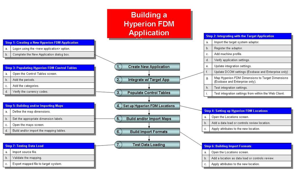
37 Module 3 Building a Hyperion FDM Application Overview Introduction The following steps outline the process for building a Hyperion FDM application: Step 1: Create a new Hyperion FDM application Step 2: Integrate the new application with the target system Step 3: Populate the Hyperion FDM control tables Step 4: Create the Hyperion FDM locations Step 5: Import maps for each location Step 6: Build import formats Step 7: Test data loading Step 8: Build validation rules and reports Figure 3-1 (right): Building a Hyperion FDM Application Flowchart. The next page includes the process flowchart expanded to show the individual sub-processes associated with building a Hyperion FDM application. Pre-Implementation Data Requirements The pre-implementation data requirements are information that must be provided by the customer in order to build a new Hyperion FDM application. Source GL Extract File an ASCII (text) file or report extracted directly from source system that has not been modified or manipulated by the end-user. The source file must contain account number, account description, amount and any additional dimensions for each record. Ideally, this file should not be an *.xls (Microsoft Excel) file. If the file contains multiple entities, the entities must also be identified for each record. Account Mapping File this file maps the source system accounts to the target system accounts. Valid mapping files include LedgerLink extracts (*.tra), Hyperion Conversion Table extracts, Microsoft Excel maps, any other mapping sources including databases. Entity Mapping File this file maps the source system entities to the target system entities. Valid mapping files include LedgerLink extracts (*.trn), Hyperion Conversion Table extracts, Microsoft Excel maps, any other mapping sources including databases. Custom Dimension Mapping Files source system custom dimensions mapped to target system custom dimensions. Section A Section B Section C Section D Section E Hyperion FDM Basics 3-1
38
39 Section B: Building a Hyperion FDM Application In this Section: Module 4: Creating a Hyperion FDM Application Module 5: Integrating the Adaptor Module 6: Populating Control Tables Module 7: Creating Hyperion FDM Locations Module 8: Importing Mapping Tables Module 9: Building Import Formats Module 10: Testing Data Load
40
41 Module 4: Creating a Hyperion FDM Application
42
43 Module 4 Creating a Hyperion FDM Application Overview The first step in building a Hyperion FDM application is to create a new application when you first log onto Hyperion FDM. A new Hyperion FDM application can be created using the Hyperion FDM Web Client or the Hyperion FDM Workbench. The procedure outlined in this section is a summarized version of the procedure demonstrated in Section A. Refer to Section A for detailed information about creating a new application. Procedure Creating a New Hyperion FDM Application a. Log onto Hyperion FDM using the <new application> option. b. Complete the New Application dialog box. Section A Section B Section C Section D Section E Building a Hyperion FDM Application 4-1
.")
44 Hyperion FDM Administrator Training Guide a. Log onto Hyperion FDM Using the <New Application> Option Launching the Hyperion FDM Web Logon or Workbench Client will display the Logon screen (Web Client shown). Select <New Application> from the Application: dropdown window and enter the name and password. Click. The New Application dialog will be displayed. b. Complete the New Application Dialog Box Figure 4-1: Create a new Hyperion FDM Application when logging onto Hyperion FDM using the Application dropdown. The New Application form contains the information that defines the name and location of a Hyperion FDM application. The form is comprised of two pages accessible by tabs a General tab and a Database tab. The General tab is used to define the Hyperion FDM application name and the application description. The General tab is also used to establish where the Hyperion FDM application architecture will be stored (Path field). The Database tab is used to name the RDBMS database that will store all of the Hyperion FDM transaction data For more detailed information about the options for the database tab, refer to Creating Applications in Section A. Figure 4-2: New/Add/Modify Application Dialog Box General Tab (left) and Database Tabs (left). After the new application has been defined, select new application has been created.. A message box will be displayed to confirm that the 4-2
45 Module 5: Integrate with the Target Application
46
47 Module 5 Integrate with the Target Application Integration Overview Integration settings are used to point a Hyperion FDM application to the target application. The target application is the application to which you want to load data. Hyperion Enterprise and Hyperion Financial Management (HFM) are examples of valid target applications. After integrating with either of the target applications, import the standard reports from an XML file and copy the standard templates into the new application s folder structure. The process of integrating with the target application is competed from within the Hyperion FDM Workbench client. Note: The information in this module includes procedures for setting up integration adaptors for Hyperion Enterprise and Hyperion Financial Management. Refer to the Hyperion FDM Installation Guide for procedures to set up an Essbase adaptor. Procedure Integrating with the Target Application a. Import the target system adaptor. b. Register the adaptor. c. Add machine profile. d. Verify application settings. e. Update integration settings. f. Update DCOM settings (Enterprise only) g. Map Hyperion FDM Dimensions to Target Dimensions (Enterprise only). h. Test integration settings. i. Test integration settings from within the Web Client. Section A Section B Section C Section D Section E Building a Hyperion FDM Application 5-1
48 Hyperion FDM Administrator Training Guide a. Import the Target System Adaptor From the Workbench desktop activate the Adaptors page by clicking on the Adaptors tab. Select File Import. This will prompt the Open Import File dialog (Figure 5-1). Figure 5-1: Open File Import dialog. Locate and select the target system adaptor file from here. From within the Open Import File dialog, locate and select the target system adaptor file then click on display the Import window (Figure 5-1). Note: HETxx.xml files are Enterprise adaptors and HFMxx.xml files are HFM adaptors. The filename of the current release of the adaptor and location of the adaptor may vary. Refer to the WebLink DM Admin Guide or the Hyperion web site for more information about adaptors. From within the Import popup screen (General tab), check the items to import (Figure 5-2). Click the Options tab. This tab contains the following options: Save existing machine profile if this box is not checked, all existing machine profiles will be deleted. Remove all report groups before updating reports this option deletes existing report groups before updating the application with new reports. to 5-2

.")
.")

49 Module 5 Integrate with the Target Application Figure 5-2: Import File Dialog. Import of adaptor General Tab (HFM left), (HE center) and Options tab (right). Select/deselect the options to be used and click desktop under Target System Adaptors (Figure 5-3).. The selections will be imported and displayed on the Figure 5-3: After importing the target system adaptor it is displayed on the Hyperion FDM Workbench desktop under Target System Adaptors. Enterprise (left) and HFM (right). Section A Section B Section C Section D Section E Building a Hyperion FDM Application 5-3

.")
50 Hyperion FDM Administrator Training Guide b. Register the Adaptor Note: Adding the adaptor and setting up machine profiles needs to be completed once for every Hyperion FDM application that is created. Registering the adaptor needs only to be done one time. Skip Step C if a Hyperion FDM application using the same adaptor that has already been registered. The file will be registered for any future applications. From the Workbench desktop, select File Register Adaptor to display the Register Adaptor dialog (Figure 5-4). Figure 5-4: Select File Register Adaptor to prompt the Register Adaptor dialog. Register the adaptor using the.exe file for Enterprise or the.dll for HFM. Select the file from the list (upsenxxx.exe for Enterprise, upsfmxxx.dll for HFM) and click on 5-4). Note: The adaptors may not be in the directory used in this example. Adaptors may also be located in the root directory of the Hyperion FDM Install folder. (Figure 5-4

. Figure 5-5: Right-click on the Machine Profiles folder to add a machine profile (example for HFM).")
51 Module 5 Integrate with the Target Application c. Add Machine Profile Working from the Adaptor tab in the Hyperion FDM Workbench desktop, expand the directory titled Target System Adaptors by clicking to expand the Adaptors directory, then clicking next to the adaptor listed to open the adaptor subdirectory. Right-click on the Machine Profiles folder and select Add Machine Profile from the flyout menu (Figure 5-5). The Add Machine Profile dialog box will be displayed (Figure 5-6). Figure 5-5: Right-click on the Machine Profiles folder to add a machine profile (example for HFM). Complete the Source Machine and Target Machine information in the Add Machine Profile dialog box. Source Machine Name enter the Hyperion FDM Application server name here. Target Machine Name enter the computer name or IP address of the application server or application cluster here. User Name specify a user name, password, and domain for the local machine to override the logon method specified in the Integration Settings logon method. This computer will always use the specified user name and password to log onto the target application server and the application. The user account specified here must have access to the target application server and have appropriate security privileges, regardless of the user who is logged into Hyperion FDM. This option is generally not used, but rather the unified logon functionality in Hyperion FDM to that provides network authentication is the more preferred method. Password the Windows password for the target machine. Domain the domain for target machine. Select when finished. Figure 5-6: Add Machine Profile Dialog box. Section A Section B Section C Section D Section E Building a Hyperion FDM Application 5-5
52 Hyperion FDM Administrator Training Guide d. Verify Application Settings From the Hyperion FDM desktop, open the Administration Menu by selecting the Administration Tab. Figure 5-7: Clicking on the Administration Tab in the left menu will expose the Administration Menu. From the Administration Menu click the Application Settings link to switch to the Application Settings screen (Figure 5-8). The Applications Settings screen includes an Options pulldown field. Confirm that the System Code contains the name of the adaptor that was just added. If several adaptors currently exist in the application, they will be selectable in this field. Use the pull-down menu to select the correct system code key/adaptor for the target system and click (Figure 5-8). Figure 5-8 (right): Application Settings Screen. Select the correct system code for the target application. This example is for HFM. 5-6
53 Module 5 Integrate with the Target Application e. Update Integration Settings From the Administration Menu select Integration Settings to display the Integration Settings Screen (Figure 5-9). Select Application Name from the Options field dropdown. In the App Name field type in the name of the target application. Click integration settings. to update the Figure 5-9: Setting the target application name and logon method is performed from the Integration Settings screen. Logon Method From the Integration Settings menu, click the dropdown in the Options Field and select Logon Method (Figure 5-10). This option controls the method that Hyperion FDM uses to log onto the target system whenever Hyperion FDM makes a connection. There are two logon methods, Unified and Global. Unified the Hyperion FDM username and password are used to log onto the target system. The username and password for users to log onto the target must be the same as the Hyperion FDM username and password in order to use this option. Figure 5-10: Select Logon Method from the Integration Settings screen. Global the username and password specified in the Global Logon Information Option is passed to the target system. Using this option, all users connect to the target system using the same username and password. If a machine-specific username and password is specified in the Workbench then it will override the logon method specified above for this specific machine. Section A Section B Section C Section D Section E Building a Hyperion FDM Application 5-7
.")
54 Hyperion FDM Administrator Training Guide Global Logon Information This option is used in conjunction with the Logon Method option. If the Logon Method option is set to Global then use this option to set the user ID and password used to log onto the target system. Separate the user ID and password with a semicolon, i.e.. UserID;Password (Figure 5-11). Figure 5-11 (right): Global Logon Method options 5-8


55 Module 5 Integrate with the Target Application f. Update DCOM Settings Note: This procedure is for integrating Hyperion FDM with Hyperion Enterprise only. If integrating with Hyperion Financial Management proceed to Step H. The upsintblockhe6xg.clshypwindow object must be configured to allow access by the same UserID as is configured in the application servers. To do this first launch DCOM Config from the Run command. Figure 5-12: Launch the DCOM Configuration from the Windows Run prompt. Change DCOM Identity settings on the upsintblockhe6xg.clshypwindow object by right clicking on the object and selecting Properties. Figure 5-13: Right click on the object and select Properties Section A Section B Section C Section D Section E Building a Hyperion FDM Application 5-9


56 Hyperion FDM Administrator Training Guide From the Properties Window, select the security tab, then click. Change DCOM Security settings for Launch/ Activation Permissions & Access permissions, to Custom. Click the Edit button and ensure that the User ID running the application servers is added to the Custom permissions. If any users will be running the Workbench their User ID must also be configured in this manner. Figure 5-14: Properties Dialog - Security Tab Figure 5-15: Launch Permissions Screen 5-10

57 Module 5 Integrate with the Target Application g. Map Hyperion FDM Dimensions to Target Dimensions Note: The procedures described here apply only to an Enterprise target applications. It is not necessary for HFM. To continue with the integration for HFM, proceed to Step H. The NameCat.txt file is used to hold the Hyperion Enterprise name and category that are used to determine if an Enterprise account is calculated. The name selected should represent a typical base name, and the category selected should represent a category used to store actual data. Return to the Hyperion FDM Workbench Client and click on the scripts tab. The Script Editor directory will appear (Figure 5-16). Figure 5-16: Script Editor Directory Section A Section B Section C Section D Section E Building a Hyperion FDM Application 5-11
. Click and select a typical base name from the target application.")

58 Hyperion FDM Administrator Training Guide Open the Custom\General folder and double-click on the HET_EditNameCat script. The script will be displayed in the right side window (Figure 5-17). Figure 5-17: Script Editor Click on the run button. The Editor dialog box will be displayed (Figure 5-18). Click and select a typical base name from the target application. Click and select a category that represents one that will be loaded by the Hyperion FDM application then click. A message box will appear confirming that the script has run. Note: The Default for the Dimension Cache Switch is set to off. When set to On the dimension list values are retrieved from Hyperion FDM cache tables and not from the target system. When set to On, then the HET_UpdateDimensionCache script must be run from the Workbench in order to update the tables with the current target application dimension list values. Figure 5-18 (right): Editor 5-12
59 Module 5 Integrate with the Target Application i. Test the Integration from within the Web Client Log onto the Hyperion FDM Web Client. Open the Activities Menu by clicking the Activities Link on the left desktop menu. Select Maps from the Activities Menu (Figure 5-19). Figure 5-19: Click Maps from the Activities Menu to start testing the target application integration. Section A Section B Section C Section D Section E Building a Hyperion FDM Application 5-13


60 Hyperion FDM Administrator Training Guide On the Maps screen (Figure 5-20) click. A new row will be added to the grid. Click Browse For Target Value to display the list of target accounts. If another window is displayed with the list of accounts then the integration settings are configured correctly. Otherwise, an error will be displayed. Figure 5-20: Maps Screen Figure 5-21: List of target accounts retrieved from the target application. When this screen appears, the integration was successful. 5-14

61 Module 5 Integrate with the Target Application Import the Standard Reports Note: The reports may be in a compressed file (.zip). Zipped files must be extracted before importing into Hyperion FDM. Unzip the file into the <application name>\templates folder. From the Hyperion FDM Workbench desktop activate the Reports screen by clicking the Reports tab. Select File Import to prompt the Open Import File dialog box (Figure 5-22). Figure 5-22 Open Import File Dialog Locate and select the standard reports XML file applicable to the database that you are using (SQL or Oracle). Click and the Import dialog will be displayed. The Import box contains two tabs -- General and Options (Figure 5-23). Figure 5-23: Import dialog used to import reports into the Hyperion FDM Section A Section B Section C Section D Section E Building a Hyperion FDM Application 5-15
62 Hyperion FDM Administrator Training Guide application. General tab (left) and Options tab (right). General select the reports folder in the Import dialog (Figure 5-24). Options contains two checkboxes. The Save Existing Machine Profiles box enables/disables the machine profile override. The Remove All Report Groups checkbox enables/disables the Report Groups override. Checking this box will delete existing report groups before updating the application with new reports. Leave this box unchecked. Click 5-24). when completed with the two tabs and the reports directory will appear on the Reports tab (Figure Figure 5-24: After importing the reports, the reports directory will appear on the Reports tab. Import the Standard Templates Note: The standard template folder may be in a compressed file (.zip) named templates.zip. Extract this file into the <application name>\outbox\templates folder. 5-16
63 Module 6: Populating Control Tables
64

65 Module 6 Populating Control Tables Control Tables Overview Control tables are used to supply the values displayed in system options. These tables allow the system administrator to control the system options and POV values that users can select. The setup of the control tables can be performed in either the Hyperion FDM Web Client or the Hyperion FDM Workbench. The examples presented here were generated using the Web Client. Procedure Populating Hyperion FDM Control Tables a. Open the Control Tables screen. b. Add the Periods. c. Add the Categories. d. Verify the Currency Codes. Section A Section B Section C Section D Section E Building a Hyperion FDM Application 6-1


66 Hyperion FDM Administrator Training Guide a. Open the Control Tables Screen To access the control tables from Hyperion FDM Web Client desktop, select the Metadata Tab from the left desktop menu to display the Metadata menu. Then click on Control Tables to open the Control Tables Screen. Figure 6-1: Control Tables Screen. Switch between the Periods Table, Categories Table, and Currency Codes Table by selecting them from the dropdown menu. There are three control tables used by Hyperion FDM -- Periods, Categories, and Currency Codes. Switch between tables by selecting them from the Control Table dropdown list. The Periods Control Table allows for the definition of the valid fiscal periods that can be used by Hyperion FDM. The values in this table provide the list of possible periods that can be selected from the Period POV link. Changing the Hyperion FDM period will change where data is loaded in the target system. 6-2

67 Module 6 Populating Control Tables b. Add the Periods The Period control table allows for the definition of the valid fiscal periods available to Hyperion FDM. The values in this table provide the list of possible periods that can be selected from the Period POV link. Changing the Hyperion FDM period will change where data is loaded in the target system. Period actual date value that will be stored in the database during the trial balance load process. This field becomes part of the key that uniquely identifies each set of TB records. Prior Date Key prior fiscal period key. Used during the export process to determine if a $0.00 entry must be made in order to prevent ghosting in Hyperion Enterprise versions 4.3 or below, caused by YTD values being loaded into a periodic category. Text Description holds a text-based description of the Date key. The format of the text description is controlled by the system configuration. The format is defaulted to a monthly granularity, but can be changed to allow loading of more than 12 periods. Target Period (M), (Q), (Y), (D) holds the target system s period to which data will be loaded. Year holds the year. Select information. to add additional periods to the table. Click in any field to activate it and add/modify the Figure 6-2 Double-click in a field to activate it and add/modify information. Click Browse for Target Periods in the Target Period column to select a valid target application period. To delete a row, select the row and click. The icon will show at the left end of the row indicating that a deletion is pending. When a row has been edited, the pending. icon will show at the left of the column to indicate that the change is Changes to the table will be saved when the will be removed. button is selected and the icons on the left of the rows To cancel a pending change to a row, click the or icon at the end of the row and select Cancel Row Changes. Note: The current period (period selected in the POV) cannot be edited. Section A Section B Section C Section D Section E Building a Hyperion FDM Application 6-3

68 Hyperion FDM Administrator Training Guide c. Add the Categories The Categories Table contains the definition of data categories. These categories represent buckets in which data can be loaded. Figure 6-3: Control Tables Screen Categories View The values in this table provide the list of possible categories that can be selected from the Category POV link. Each Hyperion FDM category is associated with a target system s category. Changing the Hyperion FDM category will change where data is loaded in the target system. Category Key automatically generated by Hyperion FDM. The numeric key assigned to each category is the value that is stored during the trial balance load process. This field becomes part of the key that uniquely identifies each set of trial balance records. Category Hyperion FDM category name. Description long name for Hyperion FDM category. Target Category holds the target systems category in which the data will be loaded. Frequency holds the category frequency. Select to insert additional categories to the table. Select a cell to activate it in order to add/update information. The current category (selected in the POV) cannot be edited. Figure 6-4: Click to add a new category. Highlight an existing row to make updates to it. 6-4

69 Module 6 Populating Control Tables Use the Browse in the Target Category column to select a valid target category. To delete a row, select the row and click. The icon will show at the left end of the row indicating that a deletion is pending. When a row has been edited, the pending. icon will show at the left of the column to indicate that the change is Changes to the table will be saved when the of the rows will be removed. button is selected. After updating, the icons on the left To cancel a pending change to a row, click the or icon at the end of the row and select Cancel Row Changes. Figure 6-5: Click the icon at the left of the row to cancel changes. Section A Section B Section C Section D Section E Building a Hyperion FDM Application 6-5

70 Hyperion FDM Administrator Training Guide [ Verify the Currency Codes The Foreign Currency Table contains a list of currency codes. Currency codes are assigned to locations. The currency code will be displayed on reports. This code does not impact any calculations, and is used for notation purposes only. Currency Code contains the short description/code for the currency. Description field to provide a more detailed description of the currency. The Currency Code table is loaded with many currencies. If needed, select to the table. Select a row to make updates to an existing currency. to add additional currencies Figure 6-6: Control Tables Screen Currency Codes View Additions or updates to a table will take effect after clicking the button. 6-6

71 Module 6 Populating Control Tables Exercise 6-1a: Setting Up Control Tables Use the Hyperion FDM Web Client to complete this exercise. 1. From the Hyperion FDM Web Client log onto the Hyperion FDM application named WLTraining. 2. Add the period control tables for January through December. Remember, you must de-select the current period in order to modify it. The completed Period Control Table should look like the following: 3. Set up control tables for the following categories: WL_Actual Enter a description of FY 2005 Actuals, and a frequency of Monthly. Link to target category Actual. WL_Budget Enter a description of FY Budget, and a frequency of Monthly. Link to target category Plan. 4. Delete the category titled WLCat. The completed Category Control Table should look similar to the following. Section A Section B Section C Section D Section E Building a Hyperion FDM Application 6-7


72 Hyperion FDM Administrator Training Guide Exercise 6-1b: Setting Up Control Tables Use the Hyperion FDM Web Client to complete this exercise. 1. Using the Web Client, log onto the Hyperion FDM Application named WLTraining. 2. Add the Period control tables for January through December. Remember, you must de-select the active period in order to modify it. The completed Period Control Table should look like the following: 3. Add the following categories: ACTUAL Enter FY Actual for the description. Select CYACT as the target category and Monthly as the Frequency. Budget Enter FY Budget for the description. Select Budget as the target category and Monthly as the frequency. 4. Delete the WLCat category. Your completed Category Control Table should look similar to the following: 6-8
73 Module 7: Setting Up Locations
74
75 Module 7 Setting Up Locations Hyperion FDM Locations Overview Locations are maintained in the Locations screen. The setup of the locations can be performed in either the Hyperion FDM Web Client or the Hyperion FDM Workbench Client. Examples presented here were generated using the Web Client. Hyperion FDM Location Types Hyperion FDM maintains two types of locations; Data Load and Controls Review. Data Load location that accepts data from a source system and loads data via mapping rules to a target system. A data load location can also be assigned financial controls. Data load locations can only be children in the controls structure, they cannot be parents. Data load locations are designated by the icon. Controls Review location assigned only to financial controls. No data is loaded from a controls review location. Controls review locations are typically parents in the controls structure. A controls review location can also be a child of another controls review location. A controls review location is designated by the icon. Data loading locations have maps and are assigned an import format. Optionally, each data loading location may be assigned a logic group and validation rules. Figure 7-1: Location Types: Controls Review and Data Load Procedure Creating Hyperion FDM Locations a. Open the Locations screen. b. Add a location as data load or controls review. c. Apply attributes to the new location. Section A Section B Section C Section D Section E Building a Hyperion FDM Application 7-1


76 Hyperion FDM Administrator Training Guide a. Open the Locations Screen The Location Maintenance screen is accessed from the Metadata Menu. Select the Metadata Tab on the Web Client desktop to display the Metadata menu, then select Locations. Figure 7-2: Locations Screen 7-2
.")
. At this point the new location will be created.")

77 Module 7 Setting Up Locations b. Add New Location Select any existing location in the control structure tree and right-click on the location to access the location flyout menu. Select Add Sibling or Add Child to add a new location. Depending on your selection, the Add Sibling or Add Child dialog box will be displayed (Figure 7-3). Figure 7-3: Location Flyout Menu Select the Location Type from the dropdown (Data Load or Controls Review), name the location and select. Location names are restricted to twenty alphanumeric characters with no spaces (underscores are allowed). At this point the new location will be created. By default, a location folder will be added to the Hyperion FDM application s inbox for each location that is added. The new folder will be named the same as the location. The location folders can be used to organize GL files, journals, and other documents per location. Figure 7-4: Add Sibling Dialog By default, deleting a location will not delete the location folder. Refer to the WebLink DM Admin Guide for more information regarding location folder options. Moving Locations Locations can be moved within the locations tree by right-clicking the location to display the flyout menu and selecting Move. This will display the Move Location Dialog box. Select the appropriate options and click. Figure 7-5: Move Location Dialog Section A Section B Section C Section D Section E Building a Hyperion FDM Application 7-3
78 Hyperion FDM Administrator Training Guide c. Apply Attributes to the New Location The Location screen contains four tabs General, Workflow Behaviors, Financial Controls, and Integration Options. Figure 7-6: Locations Screen General Tab General Tab Description field used to store additional information about the location. This is useful for tracking which GL systems are in use, or other system-related information about a location. When creating a new location the default description is the same as the name of the location. Currency identifies the currency that will be loaded into the location. This currency code is only used for identification purposes in certain Hyperion FDM reports and other forms within Hyperion FDM that display data. The currency code does not impact any calculations because Hyperion FDM does not perform currency translation (optional). Parent Location a location assigned a parent will use the same mapping table as the parent. Multiple locations may have the same parent location. This is useful when multiple locations employ the same chart of accounts. If a change is made to a child or parent mapping table then the change takes place for all children and parent locations (optional). Load Type each data load location uses one of two load types, SQL Insert or Bulk Insert. SQL Insert is the default load method and should be used for locations loading smaller files (6000 records or less). The Bulk Insert load type should be selected for locations that load larger files as it is more efficient in handling larger files. Seq Map by default Hyperion FDM wildcard maps (Like, In, Between) are sorted in the Maps Form alphabetically by their rule name. The Seq. Map option allows sorting and processing maps by a numeric value rather than the default. This is useful for locations that have complicated conversion rules predicated upon processing order (i.e., a source account is included in multiple wildcard maps, therefore the sort order of the map is important to determine by which map the account must be processed). This option should be disabled for locations that do not use such complicated translation rules. Clicking on the Seq 7-4

79 Module 7 Setting Up Locations Map checkbox will display a new sequencing field in the Maps Form. Enter a number in this field to assign a numeric sort order to each map (optional). Group Tag it is possible to group multiple locations together by typing in a value in the Grouping Tag field. Locations that are grouped will be displayed in their grouping order in certain Process Monitor Reports rather than alphabetically (optional). Data Value the Data Value field is an extra dimension that is only used when integrating with multidimension target systems. This dimension is associated with a Hyperion FDM location. When Hyperion FDM creates the load file this dimension value will be entered for every data line loaded by this location. For example, the Data Value dimension is associated with the Value dimension in HFM. By default, when integrating with HFM, the Data Value <Entity Currency> will be the default value entered in the data load file if no value is entered in this field (optional). Target Adaptor When left at [None] the location will use the global adaptor (defined during the adaptor set up process). Any selection here will override the global adaptor for this location. Note: When working in Hyperion FDM screens that browse for target categories, Hyperion FDM will browse from the adaptor that is being used by the location selected in the POV. Note: All locations in an application will share the same period and category control tables. Refer to the WebLink DM Admin Guide for more information about shared control tables. Workflow Behaviors Tab Figure 7-7: Locations Screen Workflow Behaviors Tab Import Format each data load location must be assigned an Import Format before a source file can be loaded into the location. The Import Format defines the layout of the source file. When a location is initially created, it is not necessary to assign an import format at that time in order to allow administrators to setup all reporting locations at once without knowing all the source file layouts (required to load source files). Logic Group Logic Groups contain one or more logic accounts that will be generated after loading the source file. Logic Accounts are calculated accounts derived from the source data (optional). Validation Rules a Validation Rule Group contains a set of validation rules that will be displayed on the Hyperion FDM Validation Report. These Validation Rules are used by Hyperion FDM to retrieve target system data out of the target system application after completing a data load (optional). Validation Entities a Validation Entity Group contains a set of target system Validation Entities that can be consolidated and displayed in the Hyperion FDM Validation Report (optional). Section A Section B Section C Section D Section E Building a Hyperion FDM Application 7-5
80 Hyperion FDM Administrator Training Guide Financial Controls Tab Refer to Financial Controls on page 18-1 of this manual for more information regarding financial controls. Integration Options Tab This screen shows any available custom adaptor options for the adaptor selected for the respective location. Refer to the WebLink DM Admin Guide for information about custom integration options. Exercise 7-1: adding Locations Use the Hyperion FDM Web Client to complete this exercise. 1. Add a controls review as a sibling of Controls Review and name it HQ.. 2. Add a child to HQ as a controls review location. Name it North America. 3. Add two children to North America as controls review locations. Name them Division1 and Division2. 4. Add a data load location to Division1 as a child. Name it Texas. 5. Add two children to Division2. They are data load locations. Name them Michigan and Indiana. Do not assign an import format, validation group, validation rules or other location attributes at this time. The completed control structure should look like the following: 7-6
81 Module 8: Importing Mapping Tables
82

83 Module 8 Importing Mapping Tables Maps Overview The purpose of a mapping table is to map the source dimension members to their corresponding target system dimension members. A map can be loaded for each dimension in the target application defined in Hyperion FDM. There are four methods to populate maps into a location. 1. Build maps internally within Hyperion FDM 2. Build maps externally an import to Hyperion FDM (LedgerLink extract or Hyperion FDM MapLoader template). 3. Copy existing location map to another location. 4. Assign a mapped location as a parent to another location. Procedure Building and/or Importing Maps a. Define the map dimensions. b. Set the appropriate dimension labels. c. Open the maps screen. d. Build Internally, Import, Copy, or assign a Parent map. Section A Section B Section C Section D Section E Building a Hyperion FDM Application 8-1

84 Hyperion FDM Administrator Training Guide a. Define Map Dimensions From the Hyperion FDM Web Client desktop, click the Metadata tab to display the Metadata menu. From this menu select Dimensions. When loading Hyperion Enterprise it is standard to only enable the Account and Entity dimensions. When loading other target systems every Hyperion FDM dimension can be activated (Account, Entity, ICP, and Custom 1 through Custom 20). To activate a dimension, double-click the Enabled column for the dimension and check the box. Save the change by clicking at the top of the table. Figure 8-1: Dimensions screen. Double-click a cell to modify the information. Save the change by clicking at the top of the table. Dimension Attributes Dimension contains all the default Hyperion FDM dimensions. The dimension name cannot be modified. Alias allows the dimension to be set with an alternate label/name by entering in the alias of the dimension that corresponds to the target system dimension name. Hyperion FDM will display the Alias name in the dropdown box within the mapping tables and also in the Validate and Export screens. Calc Sequence allows the Hyperion FDM administrator to override the default dimension calculation order. This is used when performing conditional mapping. The default order is the order in which the accounts are displayed on the Dimensions screen. Enabled used to enable the selected dimension. When a dimension is enabled then it is possible to import, map and load data into this dimension. Use as Lookup Use as Lookup column allows administrators to use a dimension for a custom lookup table. If this field is checked then the Enabled field cannot be checked. This custom lookup dimension is used in custom scripting only. 8-2
 is accessed by using the Dimension Labels link in the Metadata menu.")


85 Module 8 Importing Mapping Tables b. Set the Appropriate Dimension Labels The Dimension labels screen (Figure 8-2) is accessed by using the Dimension Labels link in the Metadata menu. This option is used to assign source and target labels to all the Hyperion FDM dimensions. Only the dimension label can be modified. The dimension name cannot. Figure 8-2: Dimension Labels Screen. Double-click a cell to modify the information. Source Label Target Label Figure 8-3: Dimension Labels (Maps Screen shown) The dimension labels are displayed in the mapping tables, import table, and will also be displayed in the dropdown box on the Import Formats Screen. Note: Changes in dimension labels are adaptor-specific. The example here will affect dimension labels for the HFM adaptor. To change labels for a different adaptor, change the POV to a location that uses that adaptor. Section A Section B Section C Section D Section E Building a Hyperion FDM Application 8-3
86 Hyperion FDM Administrator Training Guide Attribute Dimensions In addition to the custom dimensions UD1 through UD20, Hyperion FDM also features 14 custom attribute dimensions. These are non-mappable but can be used for custom data warehousing tasks. Enabling and disabling of these dimensions is performed via the Hyperion FDM Workbench. Refer to the WebLink DM Admin Guide and the WebLink 8.3 Workbench Guide for more information about Attribute Dimensions. Exercise 8-1a: Enabling Custom Dimensions and Changing Dimension Labels Use the Hyperion FDM Web Client to complete this exercise. 1. Log onto the Hyperion FDM Application named WLTraining. 2. Activate the Custom1 dimension in the current application. Change the Alias of the Custom1 dimension to HFM Department. 3. Activate the Custom2 dimension. Change the Alias of the Custom2 dimension to HFM Prod/Salary. 4. Use the Dimension Labels screen to do the following: Edit the Account dimension and change the label to Source Account. Edit the Entity dimension and change the label to Source Entity. Edit the target User Defined1 dimension and change the label to HFM Department. Edit the target User Defined2 dimension and change the label to HFM Prod/Salary. Exercise 8-1b: Changing Dimension Labels Use the Hyperion FDM Web Client to complete this exercise. 1. Use the Dimension Labels screen to modify the dimensions as follows: Edit the Account dimension and change the label to Source Account. Edit the Entity dimension and change the label to Source Entity. 8-4


87 Module 8 Importing Mapping Tables c. Open the Maps Screen Open the Maps screen by opening the Activities menu tab and selecting Maps. The Maps form contains a dropdown list that is used to select a dimension to map. When mapping the source members it is only possible to map to valid input target values because Hyperion FDM will only display valid input values in the target dimension dropdown list box. The Account dimension s mapping table contains an extra field that is used to control sign conversion. This field is titled - and contains a check box that when checked will change the sign of the balance of the incoming account from a positive to a negative or from a negative to a positive. Map Types GL accounts can be converted with either one-to-one mapping, or wildcard mapping. One-to-one mapping is referred to as explicit mapping in Hyperion FDM. In, Between, and Like maps are wildcard conversions. There are four mapping types for each dimension -- Explicit, Between, In, and Like. Use the Type dropdown field to select between the different types of maps. Figure 8-4: Select the mapping type using the radio buttons. Explicit Mapping (one-to-one) Explicit mapping is used in circumstances where the translation is one-to-one, where each incoming account will be assigned a target account. Start mapping a source account to a target account by identifying the account structure of the incoming general ledger account. Identify and document each account segment. Then, determine which level the account will be translated into the target consolidation system account. Example Account Structure TT = Account Type = Division PP = Primary Account Code = Location SS = Sub Account = Department Section A Section B Section C Section D Section E Building a Hyperion FDM Application 8-5
88 Hyperion FDM Administrator Training Guide Sample Accounts Cash - Disbursement Cash - Lock Box Accounts Payable Trade Accounts Payable Inter-company This sample account structure could be mapped at two different levels. If the target system account structure is aggregated so that no distinction is made between Cash Disbursement and Cash Lock Box, then the incoming source account could be truncated after the Primary account Segment. On the other hand, if the target consolidation system account structure has a level of detail equal to the incoming general ledger, the account must be mapped at the more detailed sub account level. The sample maps below illustrate this point. Primary Level Map (TTPP) GL Primary Account, Consolidation Account 0011, Cash 2235, AP Sub Account Level Map (TTPPSS) GL Primary Account / Sub-Account, Consolidation Account , Cash , Cash , AP , AP.02 Wildcard Mapping Hyperion FDM provides the greatest possible flexibility with respect to mapping source records to target records through the use of wildcard translation rules. The use of translation rules allows reduced conversion table maintenance. All incoming translated records are stamped with the translation rule that was used to provide the record with its target values. This process creates a static map for each location, category, and period combination, ensuring a static audit trail. Hyperion FDM offers additional flexibility and power when it comes to account mapping. General ledger accounts can be grouped into a calculated account, and that calculated account could then be mapped to the appropriate target account. There are three basic criteria types that can be used to create a wildcard/ calculated account. The process for creating wildcard accounts is the same as the process as creating standard account mapping. However, a wildcard rule name and rule definition must also be created and a target account must be assigned to the rule. Example: if accounts are cash accounts, wildcard mapping would be coded as follows: Rule Name Rule Desc Rule Definition Target Account wcash Cash Accounts 1000, Note: the example above is for Hyperion Enterprise. HFM does not allow periods in the target account. 8-6

.")
89 Module 8 Importing Mapping Tables Between Mapping Figure 8-5: Between Calculation on account range (Syntax: xxxxx, zzzzz) When creating a Between mapping, ensure that each side of the mapping range is the same length. For example: , is a valid mapping while , 2991 is not. This is especially important if another mapping would catch any unmapped items , 2991 would fail to catch through Additionally, Between mappings must be the same length to ensure accounts use the correct map. For example: If mappings 1530, 1540 and , both exist and an account 1540 is imported then it would be processed by the second mapping ( , ). In Mapping Figure 8-6: Calculation on list (Syntax: xxxxx, bbbbb, aaaaa) In mappings allow a list of non-sequential source accounts to be mapped to a single target account. Multiple accounts can be mapped to a single account within a single rule, eliminating the need to create multiple rules in the Explicit Map. The example above shows that source accounts 2300, 2450, and 2469 will all be mapped to the target account titled Advertising. Section A Section B Section C Section D Section E Building a Hyperion FDM Application 8-7

90 Hyperion FDM Administrator Training Guide Like Mapping Figure 8-7: Like Calculation by relation (Syntax: xxx* or xxx?x) Like mappings use the wildcard characters * and?. The asterisk designates a placeholder for any number of characters. In the example above, 1190* would map account 1190, , and accounts all to the Cash target account. The question mark wildcard acts as a placeholder for one character. For example, a source account of 119? would only map source accounts that contain four characters, and only those that begin with 119. Automap Wildcarding Hyperion FDM allows for the derivation of the target account or entity by allowing you to place wildcard characters (* and?) in both the source dimension and target dimension of the mapping table. When a mapping table contains an entry that has wildcard characters in the source and target columns the record is considered to be an Automap. Example Automap Account Conversion Table Automap Entry Rule Name, Rule Desc, Rule Value, Target Account w0011--, Cash Accts, 0011??, Cash.?? Sample General Ledger Trial Balance Records GL Account, Center, Description, Amount , , Cash In Bank, , , Cash Corp LB, , , Petty Cash, , , AP, Resulting Record Conversion GL Account Description Hyperion Acct > Cash > Cash > Cash

91 Module 8 Importing Mapping Tables Explanation The criteria for the Automap entry (Like 0011??) would have retrieved the first three records from the sample general ledger trial balance. Because the Automap entry contains wildcard characters in the target account field, Hyperion FDM knows that it must look to the source account to replace the wildcard characters in the target account with actual characters from the source account. Consequently, the characters represented by the two -- in the source account were used to replace the two? s in the target account. Next Hyperion FDM checks to make sure that the new target accounts (Cash.00, Cash.01, Cash.16) are valid target accounts, if so, the derived values are assigned to the trial balance as the target account values. Building Maps in MapLoader Mapping tables can be created in Microsoft Excel and imported into Hyperion FDM. Microsoft Excel is typically used to build conversion tables when no prior maps exist. MapLoader.xls may be used to build maps for any valid dimension. For each dimension that is mapped a separate MapLoader file is required. For example, the source accounts and target accounts are imported into MapLoader.xls to allow construction of the account mapping table. One-to-one mappings and wildcards may be used in the template. An example of the Microsoft Excel mapping template is shown in Figure 8-8. Figure 8-8: Excel MapLoader Template On the Map tab, in the MapLoader.xls file, copy the source account numbers and source account description to their respective columns. On the DimensionLists tab, in the Account Section, copy all the base level target accounts and their descriptions to their respective columns. The base level target accounts will then be accessible on the Map tab, by right clicking in the cells in the Target Column. Note: Do not add rows into the map tab as there are formulas hidden that are important when importing this file into Hyperion FDM. Section A Section B Section C Section D Section E Building a Hyperion FDM Application 8-9
92 Hyperion FDM Administrator Training Guide d1. Import Maps MapLoader Files Note: Verify that the location ID in the MapLoader file corresponds to the location ID assigned to the location by Hyperion FDM. Refer to the Instructions tab of the MapLoader.xls regarding complete use of the file and syntax for wild cards. Click the Upload File tab to browse for the mapping table if it is not already in the application s Inbox. Click Select File from Inbox tab if the map is in the Inbox. Click to find and upload the file or to select the map from the Inbox. Figure 8-9: Mapping files are imported from the Maps screen. Upload (top) or Select from Inbox (bottom). After the file has been uploaded, click to complete the import of the mapping file. The map will be loaded into Hyperion FDM for the location indicated in the mapping file. Repeat this procedure for all maps and dimensions. In mappings cannot be created in MapLoader and imported into Hyperion FDM. In mapping rules can only be created from within Hyperion FDM 8-10
93 Module 8 Importing Mapping Tables Exercise 8-2a: Importing Microsoft Excel MapLoader Maps Use the Hyperion FDM Web Client to complete this exercise. The mapping files for this exercise can be found on the training CD. 1. Navigate to the Texas location and find the location ID. 2. Open the MapLoader_TX_Accts HFM.xls file and type in the Location ID in Cell B2. Do the same for the MapLoader_TX_ICP HFM.xls file and the MapLoader_ TX_Entities HFM.xls file. 3. In Hyperion FDM, set the POV to location Texas, period Jan-2005, and Actual as the Hyperion FDM category. 4. From the Maps screen, select the FM Account dimension and import the Texas account map. 5. Change the dimension to ICP and load the intercompany map. 6. Change the dimension to FM Entity and load the Entity map. Exercise 8-2b: Importing Microsoft Excel MapLoader Maps Use the Hyperion FDM Web Client to complete this exercise. The mapping files for this exercise can be found on the training CD in the following folder: Hyperion FDM Training 8x\Enterprise\DM Enterprise Training Files\Michigan Enterprise. 1. Navigate to the Texas location and find the location ID. 2. Open the MapLoader_TX_Accts.xls file and type in the Location ID in Cell B2. 3. In Hyperion FDM, set the POV to location Texas, period JAN-2005, and Actual as the Hyperion FDM category. 4. From the Maps screen, select the Ent Account Dimension and import the MapLoader_TX_Accts.xls mapping file. Section A Section B Section C Section D Section E Building a Hyperion FDM Application 8-11
 or (*.trn).")
, semicolon (;), exclamation point (!), and comma (,).")
94 Hyperion FDM Administrator Training Guide LedgerLink Conversion Tables Hyperion FDM has the ability to read and import Hyperion LedgerLink Account and Name conversion tables. LedgerLink Conversion tables must have the file extension (*.tra) or (*.trn). If ranges are used in the LedgerLink Conversion tables, Hyperion FDM will properly interpret these as wildcards and generate the appropriate conversion table entry. Acceptable field delimiters are pipes ( ), semicolon (;), exclamation point (!), and comma (,). Note: Because LedgerLink extracts don t include a location or dimension ID, the location in the POV and the dimension for the map to be loaded must be set before importing. Hyperion FDM will import.tra and.trn files to the currently-selected POV and dimension. Select the dimension in which to load the mapping table from the Dimension dropdown menu. Click the Upload File tab to browse for the mapping table if it is not already in the application s Inbox. Click Select File from Inbox tab if the map is in the Inbox. Click to find and upload the file or to select the map from the Inbox. Figure 8-10: Mapping files are imported from the Maps screen. Upload (top) or Select from Inbox (bottom). After the file has been uploaded, click The imported map will show in the mapping table (Figure 8-11). to complete the import of the mapping file. 8-12

95 Module 8 Importing Mapping Tables Figure 8-11: Imported Mapping Table Select the next dimension in which to import the next map from the Dimension dropdown menu and repeat the steps above to finish loading all the maps for the application. Hyperion Enterprise Conversion Tables Hyperion FDM can read and import Hyperion Enterprise account and entity conversion tables. These files must have the file extension *.asc. Acceptable field delimiters are pipes ( ), semicolon (;), exclamation point (!), and comma (,). Account Conversion Table Format/Hyperion FDM Equivalent The word sub designates that this account should have its sign changed which will be indicated by a check being placed in the Minus column of the account conversion table grid. Other values that can be used to indicate a sign change are Subtract (-), True, and Yes. The word add designates that this account should not have its sign changed which will be indicated by no check being placed in the Minus column of the account conversion table grid. Other values that can be used to indicate a no sign change are Add (+), False, and No. Sample Hyperion Enterprise Account Table ! USL!SUB 002!002.INP ! US!ADD 005!005.INP Section A Section B Section C Section D Section E Building a Hyperion FDM Application 8-13
96 Hyperion FDM Administrator Training Guide Exercise 8-3a: Importing LedgerLink Files for Account, Intercompany, and Custom Dimension Maps Use the Hyperion FDM Web Client to complete this exercise. Mapping files for this exercise can be found on the training CD: 1. Open the Hyperion FDM Application named WLTraining. 2. Open the Maps screen and set the location POV location to Michigan and category to Actual. 3. Select the Account dimension from the dimension dropdown menu and import the MichiganSourceAccountHFM.tra map. 4. Change the Map dimension to ICP and import the MichiganICP HFM.tra map. 5. Change the Map dimension to HFMDepartment and import the Custom1 mapping file named Michigan Source Dept HFM.tra. 6. Change the Map dimension to Custom2 and import the Custom 2 mapping file named Michigan Source ProdSalary HFM.tra. Exercise 8-3b: Importing LedgerLink Files for Account Maps Use the Hyperion FDM Web Client to complete this exercise. 1. Set the POV to location of Michigan, JAN-2005 as the period, and ACTUAL as the Hyperion FDM category. 2. Navigate to the Maps screen. 3. Select the Ent Account dimension from the Dimension dropdown list and import the MichiganExportHE.tra map. 8-14
. Select the location and click.")
97 Module 8 Importing Mapping Tables d2. Copy Mapping Tables Set the POV to the location to be copied then open the Maps screen. Clicking the Copy button prompts the user for the target location to copy to (Figure 8-12). Select the location and click. After the target location is selected, Hyperion FDM will only copy the active conversion table from the current location to the target location. Note: Only the active dimension conversion table will be copied. Figure 8-12: Selecting the Copy button on the Maps screen will prompt the user to select a location to where the map will be copied. Exercise 8-4a: Copying Mapping Tables Use the Hyperion FDM Web Client to complete this exercise. 1. Set the POV to the Texas location. 2. On the Maps screen, set the dimension to FM Account and copy the Texas map to the Indiana location. 3. Change the map dimension to ICP and copy the Texas map to the Indiana location. 4. Set the POV to Indiana and confirm that the maps were copied. Exercise 8-4b: Copying Mapping Tables Use the Hyperion FDM Web Client to complete this exercise. 1. Set the POV to the Texas location. 2. On the Maps screen, set the dimension to Ent Account. 3. Copy the Texas map to the Indiana location. 4. Set the POV to Indiana and confirm that the map was copied.. Section A Section B Section C Section D Section E Building a Hyperion FDM Application 8-15

98 Hyperion FDM Administrator Training Guide d3. Assign a Parent Map A location assigned a parent will use the same mapping table as the parent. Multiple locations may have the same parent location. This is useful when multiple locations employ the same chart of accounts. If a change is made to a child or parent mapping table then the change takes place for all children and parent locations. Figure 8-13: Assign a parent in the Locations screen. The Nevada location has been assigned Texas as its parent. The two will share the same maps. 8-16
99 Module 8 Importing Mapping Tables Additional Mapping Features and Information Conditional Mapping Conditional mapping allows a source dimension value to be mapped to a script expression rather than a hardcoded target system dimension member. Conditional mapping is only valid for rule-based mapping (Between, In, and Like). Activate conditional mapping by placing value #Script in the Target Member column. This will trigger the script listed in the Script column to execute. The script is written in the Script column. Conditional map value logic is written in VBScript and provides all the functionality contained in the VBScript language and access to the running instance of the Hyperion FDM API. Using conditional mapping in conjunction with dimension processing order allows for mapping to be based on the results of dimension mapping performed on dimensions that have been mapped prior to the current dimensions being processed. Example If the Account and Entity dimension process prior to the ICP dimension and the ICP dimension uses a conditional mapping rule, the varvalues array will contain the mapped values for Account and Entity when the ICP dimension is processed, but the mapped values for all other dimensions will be null. Sample Condition map entry for ICP is shown in Figure Edit Delete Rule Rule Rule Target Script wall All #Script If varvalues(14) = InterCoAP Then Result = Michigan Else Result = [ICP None] End If Figure 8-14: Sample condition map entry for ICP. Explanation of Script ICP dimension conditional Script that checks the mapped value of the ACCOUNT dimension to determine how to map ICP. Check element 14 of the varvalue array to get converted/mapped account If varvalues(14) = InterCoAP Then Mapped value = InterCoAP map to Michigan Result = [Michigan] Else All others, map to none Result = [ICP None] End If Section A Section B Section C Section D Section E Building a Hyperion FDM Application 8-17
100 Hyperion FDM Administrator Training Guide The following table defines the preset variables are available for use in a conditional script expression: Values API object reference to running API strloc string value containing the name of the current location being processed VarValues a variant array containing the record values being mapped and values for proceeding dimensions already mapped Variable Record Value Mapped Variable Type varvalues(1) = Current Location ID number Long Integer varvalues(2) = Current Category ID number Long Integer varvalues(3) = Current Period Key value Date varvalues(4) = Current DataView String, Default = YTD varvalues(5) = Currency key assigned to the location String varvalues(6) = Calculation type for the current record Long Integer, 9 = Base, 5 = Logic Export, -1 = Logic (No Export) varvalues(7) = Sign Change flag for current record Boolean, 0 = False, -1 = True varvalues(8) = Journal ID for current record String, Null string if not a journal varvalues(9) = Amount for current record Double varvalues(10) = Supplemental Amount for current record varvalues(11) = Account description for current record String varvalues(12) = Supplemental Account description for current record varvalues(13) = Source Account String Double, 0 unless populated by a custom script String, Null unless populated by a custom script varvalues(14) = Target Account String, Null if this dimension has not processed yet varvalues(15) = Source Entity String varvalues(16) = Target Entity String, Null if this dimension has not processed yet varvalues(17) = Source ICP String varvalues(18) = Target ICP String, Null if this dimension has not processed yet varvalues(19) = Source UD1 String varvalues(20) = Target UD1 String, Null if this dimension has not processed yet varvalues(21) = Source UD2 String varvalues(22) = Target UD2 String, Null if this dimension has not processed yet varvalues(23) = Source UD3 String varvalues(24) = Target UD3 String, Null if this dimension has not processed yet varvalues(25) = Source UD4 String varvalues(26) = Target UD4 String, Null if this dimension has not processed yet varvalues(27) = Source UD5 String varvalues(28) = Target UD5 String, Null if this dimension has not processed yet varvalues(29) = Source UD6 String varvalues(30) = Target UD6 String, Null if this dimension has not processed yet varvalues(31) = Source UD7 String) varvalues(32) = Target UD7 String, Null if this dimension has not processed yet varvalues(33) = Source UD8 String varvalues(34) = Target UD8 String, Null if this dimension has not processed yet varvalues(35) = Archive Document ID number for this record Long Integer Table 1: VarValue Variable Definitions 8-18
101 Module 8 Importing Mapping Tables Map Processing Order Hyperion FDM processes maps within a specific order. This mapping order is important if the same source value falls within multiple maps types (i.e., Explicit, Between) and also if the same source value falls within the same mapping type multiple times. Processing Order Across Multiple Mapping Types Hyperion FDM maps the same source value when it falls across multiple mapping types in the following order: 1) Explicit 2) Between 3) In 4) Like. In summary, Explicit maps override every other mapping type. Between maps override In and Like maps. In maps override Like maps. Processing Order within the Same Mapping Type Below is a summary of how Hyperion FDM maps the same source value when it falls within the same mapping type multiple times. Between Maps If a source account is picked up by multiple Between maps then the source account will be assigned to the last Between map in the mapping table. In Maps If a source account is picked up by multiple In maps then the source account will be assigned to the first In map in the mapping table. Like Maps If a source account is picked up by multiple Like maps then the source account will be assigned to the first Like map in the mapping table. By default, Hyperion FDM wildcard maps (Like, In, Between) are sorted alphabetically by the Rule Name field. Enabling map sequencing in the Locations Form allows for the ability to sort and process maps by a numeric value rather than the sorting alphabetically by rule name. See Module 7 for additional information about map sequencing. Section A Section B Section C Section D Section E Building a Hyperion FDM Application 8-19

102 Hyperion FDM Administrator Training Guide Restoring Maps Every time a file is imported for a category or period, Hyperion FDM saves a copy of the mapping file associated with the import file. To restore a map that was used in a previous period or for a different category, click the button. The Map Restore dialog will be displayed. The Map Restore Dialog includes mappings for all periods and/or categories used for the current location. From the list, select the map to restore to the current POV. Figure 8-15: Restore Maps Dialog 8-20
103 Module 9: Build Import Formats
104

105 Module 9 Building Import Formats Overview of Import Formats Each data load location must be assigned an import group that will be used when importing data files. Import groups instruct Hyperion FDM how to interpret data files and transform them into data that can be loaded into the Hyperion FDM data structure. The Import Formats form (Figure 9-1) is arranged in a master/detail format. The top grid shows import groups, and the bottom grid is where the fields for a group are defined. By creating an import format, Hyperion FDM is able to interpret the file layout. Once the import format is created, it is important that the source file layout be unchanged each time you load data. If the file format of the source file changes, the import format will need to be updated. Figure 9-1: Build Import Format Screen. The upper table contains the Import Groups. The lower table contains the group fields. Procedure Building Import Formats a. Create a new import group b. Define import field for the import group c. Assign import format Section A Section B Section C Section D Section E Building a Hyperion FDM Application 9-1


106 Hyperion FDM Administrator Training Guide a. Create a New Import Group Click Import Formats from the Metadata menu to display the Import Formats Screen. Click screen.. This will add an additional line in the upper table of the Import Formats Specify the name and description of the import group. Select whether the file is fixed or delimited. If the file type is delimited, then select what type of delimiter is used for the file. Click Save ( ) to complete the creation of the new import group. Note: Rather than importing in a text file it is also possible to build an integration script or use a target system adapter to import the ledger data directly from an ODBCcompliant data source by selecting Script or Adapter in the File Type column. For information regarding these two file types consult the WebLink DM Admin Guide. Figure 9-2: Adding a new import format. 9-2

107 Module 9 Building Import Formats b. Define Fields for the Import Group Building a Fixed Type Import Format Click above the lower table. A new record will show. There are three attributes that are required, and one attribute that is optional for each field. Field Name (required) Start (required) the start position of field to import Length (required) length of the field to import Expression (optional) edits or interprets the field to which it is assigned Select the field name from the dropdown list in the Field Name column (Figure 9-3). Figure 9-3: Select the Field Name to Import from the Field Name dropdown list. Section A Section B Section C Section D Section E Building a Hyperion FDM Application 9-3

108 Hyperion FDM Administrator Training Guide Select located above the lower table to prompt the Import Format Builder screen. The Import Format builder will display the GL file in the internal Hyperion FDM text editor. From the Import Format Builder screen click to locate and open the file to import. After importing the file, the file contents will be shown in the Import Format Builder window/text editor (Figure 9-4). Figure 9-4: Example of fixed source file in the Hyperion FDM internal text editor. Define the start position and length of the field. For each field. You can type the start and length values directly into the fields, or you can use the drag and drop feature from within the Import Format Builder window. In the Import Format Builder Screen, highlight the text to import for the field then drag the highlighted field to the box. The Start and Length fields will automatically be populated. Repeat this process for each field name. A field name can be used more than once. Hyperion FDM will automatically concatenate the multiple field names during the load process. Note: In the example shown in Figure 9-4, the Entity name is defined as an expression. The entity is not contained in the source file. However, Entity is a required field name. The expression in the above example, defines Center as the entity for each record in the source file. Add any expressions that are required. For example, a common expression on the Amount field is sign=,cr. This expression defines all amounts with a trailing cr as a credit balance and assigns a negative sign to the imported number. 9-4
.")
109 Module 9 Building Import Formats Building a Delimited Type Import Format From the Build Import Format screen, select an Import Group. Click above the lower table. A new record will show. There are three required attributes and one optional attribute when building an import format. Field Name can be selected from a dropdown list (required). Field Number the field number to import (required). # of Fields the total number of fields for a row in the source file (required). Expression edits or interprets the field to which it is assigned (optional). Select the field name to import to from the dropdown list in the Field Name column. Figure 9-5: Select the Field Name to Import from the Field Name dropdown list. Enter the field number and number of fields in the corresponding columns. Or, you can use the Hyperion FDM drag-and-drop feature to populate these fields. Select located above the lower table to prompt the Import Format Builder screen. Section A Section B Section C Section D Section E Building a Hyperion FDM Application 9-5
.")
110 Hyperion FDM Administrator Training Guide From the Import Format Builder screen click to locate and open the file to import. After importing the file, the file contents will be shown in the Import Format Builder window (Figure 9-6). Figure 9-6: Import Format Builder Screen/Internal Text Editor In the Import Format Builder Screen, highlight the text to import for the field then drag the highlighted field to the box. The Field Number and Number of Fields fields will automatically be populated. Repeat this process for each field name. A field name can be used more than once. Hyperion FDM will automatically concatenate the multiple field names during the load process. Note: In the previous example, the Entity name is defined as an expression. The entity is not contained in the source file. However, entity is a required field name. The expression in the above example defines Center as the Entity for each record in the source file. Note: When Hyperion FDM reads in a source file, it will automatically skip every line that does not contain a valid amount, although scripts in the Amount field will still be executed. 9-6
111 Module 9 Building Import Formats Exercise 9-1: Building an Import Format for a Fixed File Use the Hyperion FDM Web Client to complete this exercise. 1. Log onto the WLTraining Hyperion FDM file. 2. Open the Import Formats screen. 3. Create a new Import Format group with the following attributes: Name = NorthAmerica Description = North America Import Format File Type = Fixed and delimiter = NA 4. Create the fields for the North America Import Group. Use the Build button to open the Texas_GL.glo file to use the drag-and-drop feature to build the import format. Build the format with the following fields: SourceEntity must be part of every record but isn t included in the.glo file. Enter 1 in the Start and Length fields, and Center in the expression field. SourceAccount Account column in the source file AccountDescription Description column from the source file Amount Ending Balance column from the source file. Add sign=,cr in the Expression column. The completed import format should look similar to the one shown below. Section A Section B Section C Section D Section E Building a Hyperion FDM Application 9-7

112 Hyperion FDM Administrator Training Guide Exercise 9-2: Building an Import Format for a Fixed File (Adding Additional Fields) Use the Hyperion FDM Web Client to complete this exercise. 1. Log onto the WLTraining Hyperion FDM file. 2. Select the North America import format. 3. Add fields to the North America Import Group. Use the Build button to open the Texas_GL.glo file to use the drag-and-drop feature to build the import format. Append the format with the following fields: SourceICP Account column in the source file HFMDepartment Third set of digits in the Account column from the source file (columns 10, 11, and 12) HFMProd/Salary Fourth set of digits in the Account column from the source file (columns 14 and 15) The completed import format should look similar to the one shown below. 9-8

113 Module 9 Building Import Formats Exercise 9-3a: Building an Import Format for a Delimited File Use the Hyperion FDM Web Client to complete this exercise. 1. Log onto the WLTraining Hyperion FDM file. 2. Open the Import Formats screen. 3. Create a new Import Format group with the following attributes: Name = Indiana Description = Indiana Import Format File Type = Delimited and delimiter = comma 4. Create the fields for the Indiana import group. You can use the Build feature to assist with building the import format, or key in the field parameters. Build the format with the following fields: SourceEntity Must be part of every record but isn t included in the.csv file. Enter 1 in the Field No. and # of Fields fields, and Center in the expression field. SourceAccount First of the three fields in the source file AccountDescription Second of three fields in the source file Amount Last of the three fields in the source file. SourceICP First of the three fields in the source file. The completed import format should look similar to the one shown below. Section A Section B Section C Section D Section E Building a Hyperion FDM Application 9-9
114 Hyperion FDM Administrator Training Guide Exercise 9-3b: Building an Import Format for a Delimited File Use the Hyperion FDM Web Client to complete this exercise. 1. Log onto the WLTraining Hyperion FDM file. 2. Open the Import Formats screen. 3. Create a new Import Format group with the following attributes: Name = Indiana Description = Indiana Import Format File Type = Delimited and delimiter = comma 4. Create the fields for the Indiana import group. You can use the Build feature to assist with building the import format, or key in the field parameters. Build the format with the following fields: SourceEntity Must be part of every record but isn t included in the.csv file. Enter 1 in the Field No. and # of Fields field, and Center in the expression field. SourceAccount First of the three fields in the source file AccountDescription Second of three fields in the source file Amount Last of the three fields in the source file. The completed import format should look similar to the one shown below. 9-10

115 Module 9 Building Import Formats c. Assign Import Formats Import groups will not be used until they have been assigned to a location. After an import format has been created, assign it to a location in the locations screen. Open the Locations Screen and activate the Workflow Behaviors tab. From here, select the import format to use for the selected location from the Import Format dropdown field. This format will then be used automatically every time a trial balance is imported for that location. A single import format can be used for many locations. If your company has a standard trial balance file format, then all locations can share the same import format. Figure 9-7: Locations Screen. Select the import format from the Import Format dropdown menu. Exercise 9-4: Assigning an Import Format to a Location Use the Hyperion FDM Web Client to complete this exercise. 1. Open the WLTraining application. 2. Open the Locations screen and select the Texas location from the locations tree. 3. Assign the NorthAmerica import format to Texas. Be sure to save the change. 4. Select Michigan from the location tree. 5. Assign the NorthAmerica import format to the Michigan location. Be sure to save the change. 6. Select Indiana from the location tree and assign it the Indiana import format. Section A Section B Section C Section D Section E Building a Hyperion FDM Application 9-11
116 Hyperion FDM Administrator Training Guide Import Function Features Skip Use the Skip function in the import format to skip over lines that are not required to be imported into the target application. Usually, these are headers or total lines. Subtotals are common lines that get skipped in import formats as well. When importing this file, each group of accounts has a subtotal with different descriptions. Importing Total or Subtotal lines can lead to inaccurate data in the target application. Figure 9-8: Sometimes an import format must be set up to skip certain lines. In this file, the Cash and Cash Equivalents:, Allowance for Doubtful Account:, and Fixed Assets: subtotal lines must not be imported to the target application. Each line that contains a subtotal does not contain a source account or characters in columns 1 through 11. By using the Skip in the field name and entering eleven spaces in the Expression field the import format will skip each line where this occurs, preventing Hyperion FDM from creating records for these subtotal lines. In lieu of typing eleven spaces in the Expression field, the drag-and-drop function can also be used. Drag the field from the Import Format Builder screen to the Expression field in the Import builder screen. In the example in Figure 9-8 the indicator used to instruct Hyperion FDM to skip a line is the colon that is included in every subtotal line in the source file. Here, the expression entered in the Expression column will be :. 9-12


117 Module 9 Building Import Formats Figure 9-9: Enter the expression in the Expression field to define the Skip feature. This example could be eleven spaces, or colon (:). Concatenating Fields Multiple fields can be joined to form and entire account, center, or description string. The Amount field name can only be one line item in an import format. In the example in Figure 9-10 the account string is nine digits. However, the mapping for this file uses the last 4 digits as general ledger account and the middle 2 digits as a department becomes The order of concatenation is based on the order of the lines in the import format. Figure 9-10: The three Account lines will be concatenated in order they appear in the Import Format table. Section A Section B Section C Section D Section E Building a Hyperion FDM Application 9-13

 was used for the NorthAmerica amount field to distinguish the credit balances (Figure 9-11).")
118 Hyperion FDM Administrator Training Guide Advanced Import Expressions Hyperion FDM has a set of powerful import expressions that makes it possible to read and parse virtually any trial balance file into the Hyperion FDM database. Advanced expressions are entered into the Fields grid under the Expression column. In the previous examples of import formats, expressions were used to hard code the center in Indiana and NorthAmerica. An advanced import expression (sign=,cr) was used for the NorthAmerica amount field to distinguish the credit balances (Figure 9-11). Access the import expression by double-clicking in the Expression column in the import form. This will display a flyout menu. Select Add Expression to display the Add Expression dialog. Figure 9-11: Select Add Expression from the flyout menu to prompt the Add Expression dialog. From the Add Expression dialog, select type of expression to use from the Expression Type field. The options shown in this field will differ depending on the field that is being modified in the import form (i.e., account, account description, amount, etc.) Enter the value to accompany the expression and click. The expression Add expression window will close and the new expression will be entered into the Expression field on the import form. Figure 9-12: Add Expression Dialog. 9-14
119 Module 9 Building Import Formats Sign Use this expression to handle non-standard numeric sign conventions. By default Hyperion FDM will properly interpret leading and trailing minus signs, as well as parentheses to mean a negative number. However, some files trail numbers with other characters to indicate the numeric sign. To define a custom sign the expression should follow this form: Sign = [Positive String],[Negative String]. Example Positive numbers are followed by a DR (1,000.00DR), and negative numbers are followed by a CR (1,000.00CR). Expression should be: Sign=DR,CR. Positive numbers are unsigned (1,000.00), and negative numbers are followed by a CR (1,000.00CR). Expression should be: Sign=,CR. Figure 9-13: Sign=CR used in amount row of import format. Section A Section B Section C Section D Section E Building a Hyperion FDM Application 9-15
120 Hyperion FDM Administrator Training Guide DRCRSplit = (Split Debit and Credit Columns) DRCR Split is used to parse split numeric columns. By default, Hyperion FDM assumes that any numeric value found in the position defined for the Amount field will be a debit. However, many files position debit values in the first half of the field and credit values in the second half (Figure 9-14). Figure 9-14: Source file with separate debit and credit fields. DRCRSplit function will assign a negative sign to any amounts right of the center of the DRCR column. The DRCRSplit expression allows Hyperion FDM to determine how to interpret this positioning and to assign the correct sign. DRCRSplit expression follows the format DRCRSplit = [Mid Point of the DR & CR columns]. 9-16
.")
. Figure 9-16: Imported data from file with a debit and credit columns.")
121 Module 9 Building Import Formats The Amount column in the source file shown in Figure 9-14 begins at column 46 and is thirty-one characters long. The midpoint of the amount field is 16. Everything left of the midpoint is a debit and everything right is a credit. Therefore, the expression in the import format for Amount will be DRCRSplit=16 (Figure 9-15). Figure 9-15: Format for using DRCRSplit in import format. The entire DRCR field is 32 characters long, therefore the halfway point in the DRCR format is entered as 16. Compare the original file to the imported file. Notice all credit amounts in the imported file have a negative sign (Figure 9-16). Figure 9-16: Imported data from file with a debit and credit columns. Using DRCRSplit has added a negative to all amounts imported from the Credit column in the original data file. Section A Section B Section C Section D Section E Building a Hyperion FDM Application 9-17

122 Hyperion FDM Administrator Training Guide Exercise 9-5: Use of Skip and DRCRSplit Use the Hyperion FDM Web Client to complete this exercise. The Nevada.txt tile used in this exercise can be found on the training CD in the following folder: Advanced Expressions and Import Script Source Files\Nevada. 1. Open the WLTraining Hyperion FDM application. 2. In the locations screen, create a new data load location named Nevada as a child of Division1. 3. Open the Import Formats screen. 4. Create a new import format with the following attributes: Name Nevada Description Nevada Skip File Type Fixed. Delimiter type doesn t apply 5. Create the fields for the Nevada import group. Use the Build feature to assist with building the import format using the Nevada.txt GL file. Build the format with the following fields: Source Entity Must be part of every record but isn t included in the.txt file. Enter 1 in the Start and Length fields, and Nevada in the expression field. Source Account Account Number column in source Account Description Description column in source file Amount Entire length of both debit and credit columns in source file. In the Expression column, set up a DRCR split in the for the Amount field Skip Eleven blank spaces from account column that proceed a summary row in the source file The completed import format should look like the table below. 6. Open the Locations Screen and assign the import format to Nevada. 9-18
123 Module 9 Building Import Formats Fill = (Trailing Fill) Use this expression to fill a field with a particular character. This expression will evaluate the text value, read from the file, and if it is shorter than the fill expression the value will be padded according to the fill expression. The examples that follow shows the account number on the first line is (Figure 9-17). The account number after import is (Figure 9-18). Fill=EuroToUS The key word Fill=EuroToUS can be used with the amount field to trigger a number format conversion from (.,) to (,.) format (Figure 9-17). The examples that follow show the ending balance in the third row of the data file as 8.265,49 (Figure 9-18). After import the same value shows as 8, (Figure 9-19). Figure 9-17: Source data file that will be imported with a Trailing Fill format. Section A Section B Section C Section D Section E Building a Hyperion FDM Application 9-19

124 Hyperion FDM Administrator Training Guide Figure 9-18: Import format for the GL shown in Figure 9-19 (trailing fill). Figure 9-19 illustrates how the data appears after it is imported. Figure 9-19: Imported Data using Trailing Fill format. 9-20
125 Module 9 Building Import Formats Exercise 9-6: Use of Fill and Skip Use the Hyperion FDM Web Client to complete this exercise. The source GL used in this exercise can be found on the training CD in the following folder: Advanced Expressions and Import Script Source Files\UK. 1. Open the WLTraining application. 2. Open the Locations screen. 3. Create a new controls review location named Europe as a sibling to NorthAmerica. 4. Create a data load location named UK as a child of Europe. Enter UK Fill and Skip as the description. 5. Open the Import Formats screen. 6. Create a new import format with the following attributes: Name UK Description UK Fill and Skip File Type Fixed. The delimiter type is not applicable 7. Build an import format for the UK location. Use the Build function to open the source GL file titled UK Trial Balance.txt. Build the format according to the following information: Source Entity Identify with an expression of UK Source Account Account column from the source file. Use the expression Fill= (ten zeroes) in the expression column. Account Description Description column from the source file Amount Ending Balance from the source file. Enter the expression Fill=EuroToUS in the Expression column to convert a Euro formatted number into the US format. Skip Set up this field to skip any row that includes page: so that Hyperion FDM doesn t import the page number as an amount. The finished Import Format should look like the table below: 8. Open the Locations Screen and assign the import format to UK. Section A Section B Section C Section D Section E Building a Hyperion FDM Application 9-21
.")


126 Hyperion FDM Administrator Training Guide FillL = (Leading Fill) Use this expression to fill a field with a particular character (Leading Fill). This expression will evaluate the text value, read from the file, and if it is shorter than the fill expression the value will be padded according to the fill expression. Figure 9-20: Source data file that will be imported with a Leading Fill format. Figure 9-21: Import format that used with the GL file shown in Figure Figure 9-22: Imported data using Leading Fill format. 9-22

127 Module 9 Building Import Formats Exercise 9-7: Use of FillL, DRCRSplit, and Concatenating Fields Use the Hyperion FDM Web Client to complete this exercise. The source GL used in this exercise can be found on the training CD in the following folder: Advanced Expressions and Import Script Source Files\Ohio. 1. Open the WLTraining application. 2. Open the Locations screen and create a new data load location named Ohio as a child of Division2. 3. Open the Import Formats screen. 4. Create a new import format group with the following attributes: Name Ohio Description Ohio FillL and Concatenating File Type Fixed. The delimiter is not applicable 5. Build the import format for Ohio. Use the Build function to open the GL file titled Ohio.txt. Build the import format with the following attributes: Source Entity The first two digits of the account number. Some accounts are only one character long. Use the leading fill expression in the expression field to fill missing characters with zeroes Source Account Will be comprised of multiple fields from the Account Number column in the source file. Set up the first part of the source account to be the last four digits of the account number from the source file Source Account Set up the second part of the source account to be a hyphen. Enter a - in the Expression field Source Account Set up the third part of the source account to be the middle two digits of the account number from the source file. Amount Input the entire length of the Debit and Credits columns in the source file. Use the DRCRSplit function in the Expression column in order to import credits and debits correctly. Skip Set up the import format to skip any row that contains a colon in the 42 nd column of the source file. Colons in the source file precede summary columns that we do not wish to import. The finished Import Format should look like the table below. 6. Open the Locations Screen and assign the import format to Ohio. Section A Section B Section C Section D Section E Building a Hyperion FDM Application 9-23


128 Hyperion FDM Administrator Training Guide Factor = (Value) Use this expression to factor the amount read from the source file by a user-defined value. To define a custom factor, the expression should follow the format Factor = [Value]. Figure 9-23: Sample of data file to be imported using Factor. Figure 9-24: Factor being used in the Expression field. All amounts imported will be multiplied by Figure 9-25: Data after import of data with imported amounts multiplied by The Factor feature can also be used to multiply by decimals. Figure 9-26: Factor being used in the Expression field. All amounts imported will be multiplied by.001. Figure 9-27: Data file after importing using a factor of
129 Module 9 Building Import Formats Exercise 9-8: Use of Factor Use the Hyperion FDM Web Client to complete this exercise. The source GL used in this exercise can be found on the training CD in the following folder: Advanced Expressions and Import Script Source Files\California. 1. Open the Hyperion FDM Application named WLTraining. 2. Open the Location Screen and create a new data load location named California as a child of Division1. 3. Open the Import Formats screen. 4. Create a new import format group called with the following attributes: Name California Description California Factor File Type Delimited with comma as the delimiter 5. Add formats to the California import group. Open the file California.dat in the Build window. Build the format with the following fields: Source Entity Identify as the first of three fields from the source file Source Account Identify as the second of three fields from the source file Amount Identify as the third field of three fields from the source file. Divide the amounts by 1000 by entering Factor=.001 in the expression column The completed import format should look like the table below. 6. Open the Locations Screen and apply the import format to California. Section A Section B Section C Section D Section E Building a Hyperion FDM Application 9-25

130 Hyperion FDM Administrator Training Guide NZP (No Zero Suppress) Use this expression to disable zero suppression during the data load process. By default Hyperion FDM bypasses accounts in the trial balance that have a zero balance. In certain circumstances you may want to load in all accounts to ensure that values that should be zero are replaced in the target consolidation system. Enter NZP in the Expression column of the Amount field to disable the non-zero suppression. Figure 9-28: Use of NZP to override the zero suppress default. Figure 9-29: Using NZP in the expression field will import accounts with zero balances. 9-26
131 Module 9 Building Import Formats Expression Stacking and Processing Order A single field can use multiple import expressions. To stack expressions simply separate the expressions with a semi-colon, but please take into consideration the order in which the layered expressions will be processed. Expression Stacking Syntax Field: GL Account Expression List: Script=ParseAcct.txt;Fill= If expressions are stacked, Hyperion FDM will process the layered expressions in the order listed below. Please note that processing order is different for the Amount field Processing Order All Fields Except Amount Field Script Excel Fill or FillL Amount Field DRCRSplit Fill (With EuroToUS Key word only) Script Excel Sign Factor Scale NZP Section A Section B Section C Section D Section E Building a Hyperion FDM Application 9-27
132 9-28 Hyperion FDM Administrator Training Guide
133 Module 10: Test Data Loading
134
135 Module 10 Testing Data Load Data Loading Overview Having the mapping tables loaded and the import formats created has prepared Hyperion FDM to import the month end GL trial balance file and load it into the target system. The following steps will be repeated every month by data loaders to load the source GL data into the target system Procedure Testing Data Loading a. Import source file b. Validate the mapping c. Export mapped file to target system Section A Section B Section C Section D Section E Building a Hyperion FDM Application 10-1


136 Hyperion FDM Administrator Training Guide a. Import Source File The Import Form is accessed via the Workflow Menu. Select Import from the Workflow menu. The Import screen will be displayed. Select the Select File From Inbox tab to upload the file from the application s inbox, or select the Upload File tab to load the file from some other location. Figure 10-1: Import Screen. Browse to find the GL file to import. Click the or (depending on the tab selected) to locate the GL file to import. Browse to find the file to import. Click the Import button in the Import Form to import the source GL file. Hyperion FDM will use the import format assigned to the location. When the import is successful, an orange Import fish is displayed. Figure 10-2: Successful import will display the data and an orange fish. 10-2

137 Module 10 Testing Data Load b. Validate the Mapping The validate step compares the dimension mapping to the imported GL file and checks for any dimensions from the GL file that are not mapped. If a file has been imported with unmapped dimensions, those dimensions will be listed. The process cannot continue until all unmapped dimensions are mapped to a valid target. When the validation is successful the orange Validate fish will be displayed in the header. Figure 10-3: After clicking Validate, OK will be displayed next to Items: in the validate screen if all dimensions in the import GL file have been mapped. Section A Section B Section C Section D Section E Building a Hyperion FDM Application 10-3

.")
138 Hyperion FDM Administrator Training Guide Fixing Validation Errors The addition of new accounts to the general ledger system is a typical occurrence that can produce a validation error. A new account that shows up in a source file is likely to be previously unmapped. If a user has a new account and there is no mapping for the new account, the Validate fish will be white in color. The Validation screen will show the number of items that are not mapped, and therefore undefined. Fix Button Figure 10-4: During the Validate stage, any unmapped dimensions will be listed at the top. Correctly mapped dimensions will be listed at the bottom. Highlight the row to fix and select. Highlight the row to fix and click button. The dimension mapping table will be displayed (Figure 10-5). Double-click the Target Account cell to open the Target Lookup Screen. Figure 10-5: Target Key Lookup screen. Browse for the target account in which to map a dimension. 10-4


139 Module 10 Testing Data Load In the Target Account lookup screen browse to locate the target account to which the undefined source account should be mapped (Figure 10-6) the click on. Figure 10-6: Select the Target Account from the Target Key Lookup screen then click. The selected target account will now be displayed in the mapping table. Click changes. to save the Figure 10-7: Mapping screen showing retrieved account. Click to save the change. After all unmapped items have been fixed, click on the Validate button in the Hyperion FDM header to confirm the new mapping. If the mapping was successful, the orange Validate fish will be displayed. Section A Section B Section C Section D Section E Building a Hyperion FDM Application 10-5
 dimension value being mapped.")
140 Hyperion FDM Administrator Training Guide Intersection Validation Report (HFM Only) After all the mappings are validated, Hyperion FDM verifies that the account and other dimension mappings intersect at a correct dimension. The example in the Figure 10-8 shows an invalid source Prod/Salary (Custom 2) dimension value being mapped. This must be corrected before Hyperion FDM will pass the Validate step. Figure 10-8: Intersection Validation Report 10-6


141 Module 10 Testing Data Load c. Export Mapped File to Target System After all the source values have been validated, the data can now be loaded to the target system. Click in the header, or select Export from the Workflow Menu and Hyperion FDM will create a file to load to the target system in the Outbox of Hyperion FDM. The Target System Load popup screen will be displayed (Figure 10-9). Click from the Target System Load screen. Figure 10-9: Target System Load Popup Screen The Load Method dropdown list contains four options: 0-Replace, 1-Merge, 2-Accumulate, and 3-Replace by Security. If the data has been exported successfully then the export fish will be displayed. At this point your data has now been loaded into the target system. Figure 10-10: When the export is successful the Export fish will appear. Section A Section B Section C Section D Section E Building a Hyperion FDM Application 10-7
142 Hyperion FDM Administrator Training Guide Exercise 10-1a: Loading Data Use the Hyperion FDM Web Client to complete this exercise. 1. From within the WLTraining application, set the POV to location Texas, period Jan 2005, and Actual as the Hyperion FDM category. 2. From the Hyperion FDM desktop, click on IMPORT at in the top of the screen. 3. From the Import screen click import and upload the GL file titled Texas.glo. A yellow fish under IMPORT indicates a successful import. 4. Click VALIDATE in the upper portion of the screen to confirm that all source dimensions are mapped. Fix any undefined mapping errors using the Fix button displayed next to each error to map undefined accounts to valid target accounts.fix the mapping errors as follows: a. Source Account: HFM Account: b. Source Entity: Center HFM Entity: TX c. Source Department: 000 HFM Department: [None] d. Source Department: 110 HFM Department: Accounting 5. Click VALIDATE again after mapping has been updated. The Intersection Validation report will be displayed. Correct any intersection validation errors. The Source Prod/Salary that has the target dimension of Breaks (a misspelling in the imported MapLoader file) is incorrect. Change it to a valid target dimension 6. Click VALIDATE again after the intersection report errors have been corrected. The VALIDATE fish will be displayed when the VALIDATE step was successful. 7. Click EXPORT in the upper portion of the screen. In the System Load dialog box, select on applicable options and click the Load button. A successful load to the target system will be indicated by a fish displayed under the EXPORT link at the top of the screen. 10-8
143 Module 10 Testing Data Load Exercise 10-1b: Loading Data Use the Hyperion FDM Web Client to complete this exercise. 1. Log onto the WLTraining application. 2. Set the POV to location Texas, period Jan 2005, and Actual as the category. 3. The Import screen click import and upload the GL file titled Texas.glo. A yellow fish under IMPORT indicates a successful import 4. Click on VALIDATE in the upper portion of the screen, to confirm that all source dimensions are mapped. Fix any undefined mapping errors using the Fix button displayed next to each error to map undefined accounts to valid target accounts.fix the mapping errors as follows: a. Source Account: Target Account: b. Source Entity: Center Target Entity: TX.INP 5. Click VALIDATE button again after the mapping has been updated. The Validate fish will be displayed when the validation has passed. 6. Click the EXPORT link at the top of the screen. 7. In the System Load dialog box, select on applicable options and click the Load button. A successful load to the target system will be indicated by a fish displayed under the EXPORT link. Section A Section B Section C Section D Section E Building a Hyperion FDM Application 10-9
144 10-10 Hyperion FDM Administrator Training Guide
145 Section C Enhancing the Application In this Section: Module 11: Validation Rules and Reports Module 12: Validation Entities
146
147 Module 11: Validation Rules and Reports
148
149 Module 11 Validation Rules and Reports Validation Rules and Reports Overview Validation rule groups provide a way for system administrators to define a set of rules and annotations used to enforce data integrity during the data collection process. Validation rule groups are activated by assigning them to a location. When a validation rule group is assigned to a location, the Validation Report will be generated following a data load to the target system. The Validation Report will run for all entities defined in the Validation Entities group if also assigned to the location. If no Validation Entities group is assigned to the location then the Validation Report will run for each target entity that was loaded to the target system To open the validation rules screen, click on the Validation Rules link from the Metadata Menu. Procedure Building Validation Rules and Reports a. Define validation rule groups b. Define validation rules c. Attach validation rules to locations d. Check validation rules Section A Section B Section C Section D Section E Enhancing the Application 11-1

150 Hyperion FDM Administrator Training Guide a. Define Validation Rule Groups The Validation Groups form is shown in Figure Each validation rule group contains a set of administratordefined rules that perform checks and balances against the target system. To create a validation rule group, click in the upper half of the table. Type in a label and a description for the validation rule group in the corresponding columns. Click to save the changes. Hyperion FDM will automatically add the date created. Figure 11-1: Validation Rules screen showing the Validation Groups (upper table). The lower table holds the validation rules (none entered at this point). To delete a group, select the corresponding row and click. A row pending deletion will show a at the left of the column. will show at the left of a row that has been changed but not yet saved. 11-2

151 Module 11 Validation Rules and Reports b. Define Validation Rules Validation rules define the validation rule group. The Rules table is comprised of the following columns: Display Value, Description, Rule Name, Rule Text, Type, Category, Seq, and Rule Logic. Display Value This column controls how Hyperion FDM will format each row of data that is being defined. This column can be used to select a valid target account, select a report format code, or create a custom expression. The contents of this column are processed under the following rules: If the field contains a report format code then no value lookup is attempted. If the column contains anything other than a report format code, then the result of the custom expression (rule logic) is displayed in the value column. This column is limited to 75 characters. Double-clicking in the Display Value field will display the flyout menu that contains three items Zoom, Browse for Target Account, and Select Format Code (Figure 11-2). Figure 11-2: While a rule is in edit mode, the Browse and Format Code lookup link in the Display Value column are active. Zoom This option will open the cell text in a text editor. This is helpful when entering or editing large amounts of text. Browse for Target Account The Validation Rules grid allows for easy target account selection. Select this option to show the Validation Rule Target Account Lookup screen. From there select the account from the list of target system application accounts and it will be entered into the Validation Rules grid. In addition to placing the account number in the Display Value field, a custom expression is required in order to have the value displayed for the selected account. Select Format Code In addition to selecting target accounts, format codes can also be entered in the Target Account column. These codes are used to control the presentation of the Validation Report. Use this option to select the desired code from the Select Format Code screen. Table 2 explains the format codes that can be used in a validation rule. Section A Section B Section C Section D Section E Enhancing the Application 11-3
152 Hyperion FDM Administrator Training Guide Code #ModeList #ModeRule #Title #Subtitle Description Sets the report mode to Listing. This mode will display the Display Value, Description, and Amount fields in the report. (Default) Sets the report mode to Rule. This will display the Rule Name, Rule Text, and Amount in the report. The report will evaluate the expression in the Rule Logic column and test the true/false condition of this rule. The status of the rule (OK/Error) will be displayed on the report for each rule. The Target Account and Description columns are not displayed in this mode. This code inserts a title line into the report. When #Title is used, the text found in the Description field would be formatted and displayed as a title. This code forces Hyperion FDM to insert a subtitle line into the report. If #Subtitle is used the text found in the Description field would be formatted and displayed as a sub title group. Subtitles are used for report grouping and are inserted into the report navigation tree Table 2: Report Format Codes Description This column is used to display account descriptions, titles, or sub titles. This column is limited to 50 characters. This field is only displayed in the report if the report is in #ModeList. Example Description: Out-of-Balance Account Rule Name This column is used to store an identifier for a validation rule. This field is only visible in the report if the report is in #ModeRule. This value should be unique and easy to identify. Also, it is good practice to annotate each rule outside Hyperion FDM in order to document a basis for each rule. This column is limited to 255 characters. Example Rule Name Out-of-Balance Check Rule Text This field is used to define a basis or logic behind a rule. The text in this column will be the primary statement shown on the Validation Report. This field is only visible in the report if the report is in #ModeRule. This column is limited to 255 characters. Example Rule Text This account must be between [+10 and 10] Type The Type field in the Validation Rules form corresponds to the Type field in the Validation Entities form. Refer to Module 12 for more information about Validation Entity Groups. Select All for this rule to be displayed for all entities on the validation report. Select Parent for this validation rule to only be displayed in the Validation Report for entities whose type field is set to Parent or All in the 11-4
153 Module 11 Validation Rules and Reports Validation Entities form. Select Base for only be displayed in the Validation Report for entities whose type field is set to Base or All in the Validation Entities form. If a validation rule is designated as an All type then this validation rule will be displayed in the Validation Report for all entities, regardless if the entity was flagged as a base or parent entity in the Validation Entities form. Category Use this field to restrict the validation rule to a specific Hyperion FDM category. The rule will only be displayed on the validation report if the Hyperion FDM category selected in this field is the same as the active Hyperion FDM category set in the POV. Select All for the rule to be displayed on the validation report regardless of the active Hyperion FDM category set in the POV. Sequence Use this option to control the order of rule processing. Enter a sequence number that will be used to indicate the order in which the format codes and rules should be processed. It is good practice to increment the sequence number by 10 in order to provide a range for insertion of new format codes and rules. Rule Logic This field allows for a multi-dimension lookup, a validation rule expression, or a more advanced validation rule function. Multi-dimension lookups are used to display the desired value in the Amount field on the validation report. Validation rule expressions and functions are usually used to validate target system account balances. The Rule Logic field is only processed if the report is in ModeRule or ModeList. Validation rule expressions and validation rule functions use all standard Microsoft VB script language expressions. Validation rule expressions and functions test for a true/false condition. When the rule logic is processed the rule is flagged in the validation report as either passing or failing. Multi-Dimension Lookup Function This function is used to retrieve account values from within the target system and can be used in the Rule Logic field and/or the Display field. Target system accounts are referenced by enclosing the account in pipes ( ). Pipes are entered by pressing the Shift + / keys on the keyboard. Parameters that can be used when referencing a target system account are as follows: Scenario(Optional), Period(Optional), Year(Optional), View(Optional), Value(Optional), Entity(Optional), Account(Required), ICP(Optional), UD1(Optional), UD2(Optional), UD3(Optional), UD4(Optional), UD5(Optional), UD6(Optional), UD7(Optional), UD8(Optional), UD9(Optional) UD10(Optional), UD11(Optional), UD12(Optional), UD13(Optional), UD14(Optional), UD15(Optional) UD16(Optional), UD17(Optional), UD18(Optional), UD19(Optional), UD20(Optional) Using the format above will allow Hyperion FDM to retrieve values from the target system for any dimension desired. However, it is possible to reference only the target account because the other parameters are optional. Note: Validation rules can also be written to validate values directly from a Hyperion FDM source or a Hyperion FDM converted value. Refer to the WebLink 8.3 Workbench Guide for more information. Section A Section B Section C Section D Section E Enhancing the Application 11-5
 set in the Hyperion FDM POV for each entity in the Hyperion FDM Validation Entity Group that is assigned to this Hyperion FDM")
154 Hyperion FDM Administrator Training Guide The following examples illustrate the different ways that values can be retrieved from a target system: Example 1 Look up the value of the target account balance for the current target period and target scenario (category) set in the Hyperion FDM POV for each entity in the Hyperion FDM Validation Entity Group that is assigned to this Hyperion FDM location. In the following example, the rule will pass validation if the target account is within $10.,,,,,,Balance,,,,,,,,,,,,,,,,,,,,, > AND,,,,,,Balance,,,,,,,,,,,,,,,,,,,,, < Example 2 Lookup the value of the target account balance for the supplied dimensions. Actual,March,2002,,YTD,Ohio,Balance,Michigan,Engines,Ford,Trucks,[None],,,,,USD,,,,,,,,,,, >0 Example 3 Look up the value of the target account balance for the supplied dimensions and the prior period. Actual,-1,2002,,YTD,Ohio,Balance,Michigan,Engines,Ford,Trucks,[None],,,,,USD,,,,,,,,,,, > 0 Example 4 Look up the value of the target account balance for the active target scenario (category) set in the Hyperion FDM POV, the prior target period, and for each entity in the Hyperion FDM Validation Entity Group that is assigned to this Hyperion FDM location. All missing custom dimensions will be defaulted to [None]. The ICP dimension will default to [ICP-None]. The Year dimension will default to the current year set in the active Hyperion FDM POV. The Currency dimension defaults to 0 and the View dimension will default to YTD.,-1,,,,,Balance,,,,,,,,,,,,,,,,,,,,, > 0 Note: With Hyperion Enterprise it is only necessary to add the target account in the formula as long as the other parameters are left dynamic. So the formula below would lookup the value of the target account Balance for the current target period and target scenario (category) set in the Hyperion FDM POV, and for each entity in the Hyperion FDM Validation Entity Group that is assigned to this Hyperion FDM location. Balance Validation Rules Wizard The Validation Rules Wizard assists with the development of rule logic associated with items defined under the ModeList or ModeRule format codes. The Validation Rules Wizard can only be accessed from the Workbench Client From the Workbench Client, under the Metadata tab select the Validation Rule Groups by double-clicking on it (Figure 11-3). This will open the Validation Rules Table (Figure 11-4). Figure 11-3 (right): Open the Validation Rules Table by doubleclicking Validation Rule Groups under the Metadata tab 11-6


155 Module 11 Validation Rules and Reports Figure 11-4: Validation Rules Table Open the Validation Rules Wizard by double-clicking in the Rule Logic column on the row that contains the account value or rule to be defined. Figure 11-5 shows the Validation Rules Editor Text Box on a row that contains a rule to be defined. The rule name and rule text, if entered when defining the row, will be listed above the Rule Window. Figure 11-5: Validation Rules Editor. Note the rule name and rule text listed. Section A Section B Section C Section D Section E Enhancing the Application 11-7

156 Hyperion FDM Administrator Training Guide The Validation Rule Editor contains three tabs -- Rule, Lookup, and Test. The Rule tab is comprised of two windows -- rule and display. The Rule window is used to define the rule on rows under the ModeRule format code. For rows under the ModeList format code the rule window is used to define the value that will be displayed on the validation report. The bottom window is the Display window and this is used to define the value that will be displayed on the validation report for rows under the ModeRule format code. Figure 11-6: Location of the Validation Rules Accelerators (Accelerators\Validation Rules) The accelerators provided are the most common used to define specific validation rules. Double-clicking on a rule will load it into the Rule window. Figure 11-7: Double-clicking a rule in the Validation Rules folder will load the rule into the Rule window. 11-8


157 Module 11 Validation Rules and Reports Adding the accelerators to the Rule window will activate the Lookup tab. The Lookup tab can also be activated by inserting two pipes into the Rule or Display window on the rule tab as shown in Figure Figure 11-8: Inserting two pipes into the Rule or Display window on the rule tab will activate that Lookup tab. The Lookup tab screen is shown in Figure Figure 11-9: Validation Rules Editor Screen (Lookup tab) Section A Section B Section C Section D Section E Enhancing the Application 11-9

158 Hyperion FDM Administrator Training Guide All of the active fields for the HFM syntax will be bolded in blue under the Builder (Rule) column. If no value is entered into one of the blue fields then Hyperion FDM will use the current POV to determine the value. Dimension lists can be obtained for each of the blue fields by right-clicking in the dimension name and selecting Browse... to prompt a lookup box. This is illustrated in Figure Figure 11-10: The OUT_OF_BALANCE_ACCT used to define the rule. The example illustrated in Figure 11-11, the OUT_OF_BALANCE_ACCT is being used to define the rule. For this account the top hierarchy levels of the ICP, Custom1, and Custom2 dimensions must be selected. It is important to enter in the top hierarchy levels of all custom dimensions, leaving these blank could result in the wrong values being pulled from HFM. Figure shows the lookup tab fields completed. The Rule and Display windows are both completed which will result in a pass or fail situation and also the value of the OUT_OF_BALANCE_ACCT being displayed. Figure 11-11: Validation Rules Editor (Lookup tab) screen fields completed

159 Module 11 Validation Rules and Reports The completed Validation Rules table is illustrated below. Figure 11-12: Completed Validation Rules Table Test Tab The test tab allows users to test the current rule/display value to ensure that the proper results will be generated before putting the new rule into production. Figure 11-13: Validation Rules Wizard - Test Tab. To test a rule or display, activate the Test tab, then click or. This will prompt the Select Test Entity dialog. Section A Section B Section C Section D Section E Enhancing the Application 11-11


160 Hyperion FDM Administrator Training Guide Select the entity from the dialog and click. Figure 11-14: Select the entity to test from the dropdown list. Test Rule the test rule button will run the current rule in the Rule section. When clicked, Hyperion FDM will display a drop down selection of all available target location. This selection will then be used to pull values and return the rule results. Test Display the test display button will run the current rule in the display section. When clicked, Hyperion FDM will display a drop down selection of all available target location. This selection will then be used to pull values and return the display results. Expression this field displays the rule being tested. Expression After Lookup this field returns the results of the expression being tested after the lookup has been performed. This field can also be used as a scratch pad by highlighting text in the field and right clicking. Lookup Errors the Lookup Errors field will display any errors that were found in the rule being tested. Expression Results Displays the results of the rule test (TRUE or FALSE). If the location being tested with the current rule passes the validation rule then TRUE is returned. If the location does not pass then FALSE is retuned. Figure 11-15: Validation Rules Screen - Test Tab

161 Module 11 Validation Rules and Reports Exercise 11-1a: Creating Validation Rules This exercise can be completed in the Workbench or on the Web. However, the Validation Rules Wizard is only available in the Workbench. 1. Open the Validation Rule Groups window 2. Create a new validation group with the following attributes: Name NorthAmerica Description North American Validation 3. Create a set of rules for the North America validation group. Double-click inside the Display Value column to open the Validation Rules wizard. Use the wizard to develop the Rule Logic on the items under the ModeList and ModeRule sections. Create the rules with the following parameters: #Title...Description = North America Validation #Subtitle...Description = Key Data #ModeList TOT_NET_SLS...Description = Net Sales,,,,,,TOT_NET_SLS,[ICP TOP],ToTDepts,ToTProd,,,,,,,,,,,,,,,,,, GR_PROFIT...Description = Gross Profit,,,,,,GR_PROFIT,[ICP TOP],ToTDepts,ToTProd,,,,,,,,,,,,,,,,,, NET_INC...Description = Net Income,,,,,,NET_INC,[ICP TOP],ToTDepts,ToTProd,,,,,,,,,,,,,,,,,, #Subtitle...Description = Validation Rules #ModeRule OUT_OF_BALANCE_ACCT Rule Text = Out_of_Balance_Acct must be $0 ABS(,,,,,,OUT_OF_BALANCE_ACCT,[ICP TOP],ToTDepts,ToTProd,,,,,,,,,,,,,,,,,, ) =0;,,,,,,OUT_OF_BALANCE_ACCT,[ICP TOP],TotDepts,ToTProd,,,,,,,,,,,,,,,,,, The completed North America Validation Group is shown below: Section A Section B Section C Section D Section E Enhancing the Application 11-13

162 Hyperion FDM Administrator Training Guide Exercise 11-1b: Creating Validation Rules This exercise can be completed in the Workbench or on the Web. However, the Validation Rules Wizard is only available in the Workbench. 1. Open the Validation Rule Groups window. 2. Create a new validation rule group with the following attributes: Name NorthAmerica Description North America Validations 3. Create a set of rules for the North America validation group. Double click inside the Display Value column to access the format codes. Use the Validation wizard to develop the Rule Logic on the items under the ModeList and ModeRule sections. Create the rules with the following attributes: #Title...Description = North America Validation #Subtitle...Description = Key Data #ModeList NET_SLS_EXT...Description = Sales, net External GR_PROFIT...Description = Gross Profit NET_INC...Description = Net Income #Subtitle...Description = Validation Rules #ModeRule BALACCTS.TBBAL Rule Text = BALACCTS.TBBAL must be $0. Abs(,,,,,29000.BALACCTS.TBBAL,,,,,,,,,,,,,,,,,,,,,,,,,, ) = 0;,,,,,29000.BALACCTS.TBBAL,,,,,,,,,,,,,,,,,,,,,,,,,, The completed North America Validation Group is shown below

163 Module 11 Validation Rules and Reports c. Attach Validation Rules to a Location Attaching rules to a location is performed in the Locations screen. Navigate to the Locations screen, select the location in which to attach validation rules. Activate the Workflow Behaviors Tab and select the validation rule group from the Validation Rules dropdown list. Click to update the changes. Figure 11-16: Locations Screen (Workflow Behaviors Tab) where validation rules can be assigned to a location. Exercise 11-2: Attach Validation Rules to Locations Use the Hyperion FDM Web Client to complete this exercise. Be sure to save the changes for each location that is modified. 1. Open the Locations screen. 2. Attach the NorthAmerica validation rule group to Indiana. 3. Attach the North American validation group to the Michigan location. 4. Attach the North American validation group to the Texas location. Section A Section B Section C Section D Section E Enhancing the Application 11-15
164 Hyperion FDM Administrator Training Guide d. Check Validation Rules After loading the data to the target application, a validation check is performed based on the criteria specified in the Validation Rules table for the corresponding validation rules group. A validation check is only performed if a validation rules group has been assigned to the location. Figure 11-17: Validation Report If the Validation Rules are not met, it will fail the Check and this will require the user to follow up and investigate why they are out of balance in order to complete the task. Exercise 11-3: Check Process Use the Hyperion FDM Web Client to complete this exercise. 1. Set the POV to location Texas, period Jan 2005, and Actual as the category. 2. Click the EXPORT link at the top of the screen to reload the imported Hyperion FDM data into the target application. 3. In the System Load dialog form select the applicable options and click Load. Hyperion FDM will automatically run the CHECK function using the validation rules. The Validation Report will be displayed and include all of the entities that were loaded with the export file. A Check fish will be displayed under the Check link when the Validation Report has successfully passed
165 Module 12: Validation Entities
166
167 Module 12 Validation Entities Overview Validation entities provide a way for system administrators to define a set of target system entities that will be consolidated and also passed to the validation report. Validation Entities are activated by assigning them to a location on the Location Screen. If a location has a Validation Entity assigned then a consolidation will be triggered in the target system following a data load. Validation Entities are created in groups. You can have many different groups of validation entities. Procedure Building Validation Entities a. Create validation entity group. b. Define validation entities. c. Attach validation entities to a location. Section A Section B Section C Section D Section E Enhancing the Application 12-1


168 Hyperion FDM Administrator Training Guide a. Create Validation Entity Group Validation Entity Groups consist of one or more target system entities that you wish to consolidate and/or be displayed on the Validation Report. Validation Entity Groups are activated by assigning them to a location. Navigate to the Validation Entities Screen by clicking the Validation Entities Link under the Metadata Menu. The Validation Entities Form is shown in Figure To create a Validation Entity Group, click in the upper table. Type in a label and description for the Validation Entity Group in the corresponding columns. Click to save the changes. Figure 12-1: Validation Entities Screen To delete a group, select the corresponding row and click. A row pending deletion will show a at the left of the column. will show at the left of a row that has been changed but not yet saved. 12-2
169 Module 12 Validation Entities b. Define Validation Entities A Validation Entity Group consists of a target entity that can be consolidated and/or be displayed on the validation report. Multiple entities can be assigned to one Validation Entity Group. See topics below for descriptions of each Validation Entity field. Organization/Parent Entity For Hyperion Enterprise target systems, select the organization in which to consolidate the entity. For all other target systems, select the parent entity of the entity that will be consolidated. This field has no effect if the Consolidate field is not checked. Entity The Entity field contains the target entity that will be consolidated and/or displayed on the Validation Report. If the Consolidate field is checked this entity will be consolidated before being displayed in the Validation Report. Consolidate This switch is used to signal that a consolidation should be run for this entity prior to being displayed in the Validation Report. Start Period The start period controls how Hyperion FDM will execute the consolidation process within the target system. Enterprise Only If the start period is set to 0, then only the current period is consolidated. If the start period is set to a value that is greater than the current period, then only the current period is consolidated. Setting the start period value to 1 will cause Hyperion FDM to consolidate for periods 1 to current period. Entity Type The Type field in the Validation Entity form corresponds to the Validation Rule Type field in the Validation Rules form. In the Type field, select Base entity or Parent entity. Select All (default) if you do not want to distinguish whether the entity is a base or parent. The entity will then always be displayed in the Validation Report for each validation rule. For example, if an entity is designated as a Parent type then this entity will only be displayed in the Validation Report for validation rules whose Type field is set to Parent or All. If an entity is designated as a Base type then this entity will only be displayed in the Validation Report for validation rules whose Type field is set to Base or All. If an entity is designated as All then this entity will be displayed in the Validation Report for all validation rules regardless of the validation rule type. Section A Section B Section C Section D Section E Enhancing the Application 12-3
. On Report Check this field to include this entity in the validation report.")

170 Hyperion FDM Administrator Training Guide Figure 12-2: The Type field in the Validation Entity Form (top) corresponds to the Validation Rule Type field in the Validation Rules Form (bottom). On Report Check this field to include this entity in the validation report. If this field is not checked and the consolidate field is checked then the entity will only be consolidated, not shown on the validation report. Sequence This column is used to control the order of entity processing. The sequence number is used to indicate the order in which the entities will be consolidated and displayed on the report. It is good practice to increment the sequence number by 10 in order to provide a range for insertion of new entities. 12-4

171 Module 12 Validation Entities Exercise 12-1a: Create Validation Entities Use the Hyperion FDM Web Client to complete this exercise. 1. Open the Validation Entities screen. 2. Create a new Validation Entity Group with the following attributes: Name Texas Description Texas Consolidation 3. Add a validation entity to the Texas Validation entity group with the following attributes: Parent Operations Entity Texas Consolidate Yes Start Period 0 Type All On Report Yes Sequence 10 Section A Section B Section C Section D Section E Enhancing the Application 12-5

172 Hyperion FDM Administrator Training Guide Exercise 12-1b: Create Validation Entities Use the Hyperion FDM Web Client to complete this exercise. 1. Open the Validation Entities screen. 2. Create a new Validation Entity Group with the following attributes: Name Texas Description Texas Consolidation 3. Add a validation entity to the Texas Validations Entity group with the following attributes: Organization Operations Entity Texas Consolidate Yes Start Period 0 Type All On Report Yes Sequence

173 Module 12 Validation Entities c. Attach Validation Entity to a Location In order to activate validation reporting for a location, the location must be assigned a validation rule group. The validation entity group is optional. If a validation entity group is assigned to a location, the entities listed in that group will override any entities that appear on the Validation Report, otherwise, the base names that were present during the last data load will be used to supply the Validation Report. The validation rule group and validation entity group are assigned to a location on the Locations Form. Figure 12-3: Assign Validation Rule Group and Validation Entity Group from within the Locations Form. Exercise 12-2: Attach Validation Entities and Report Consolidated Results Use the Hyperion FDM Web Client to complete this exercise. 1. Set the POV to location Texas, period Jan 2005, and Actual as the category. 2. Using the texas.glo file process the Texas location through the Import, Validate, Export and Check process. The Validation report should run showing you the results from the Texas entity contained in the texas.glo file 3. Close the Validation Report. 4. Open the Locations Screen. 5. Attach the Texas Validation entity group to the Texas location. 6. Click on the Export fish and reload the Texas export file. Notice that the entities in the Validation Entity group assigned to the Texas location are now feeding the Validation Report. A consolidation was also done on the Texas Entity in the target application. Section A Section B Section C Section D Section E Enhancing the Application 12-7
174 12-8 Hyperion FDM Administrator Training Guide
175 Section D Additional Functionality In this Section: Module 13: Logic Accounts Module 14: Journals Module 15: Multiload
176
177 Module 13: Logic Accounts
178
179 Module 13 Logic Accounts Overview Logic accounts are dynamically generated accounts that are used to calculate supplemental values not provided in the source file. Logic accounts can be mapped and loaded into the target system like any other source account. Logic accounts can be used to provide a variety of functions: Statistical Loading map a single source account to multiple target accounts. Conditional Mapping map a source account based on its value. Arithmetic Mapping perform arithmetic operations on source values. Logic accounts are created in Hyperion FDM, therefore detailed audit trails on the logic account values are not available. In order to access the Logic Accounts form, select Logic Groups from the Metadata menu. The Logic Group Form is shown in Figure Section A Section B Section C Section D Section E Additional Functionality 13-1

180 Hyperion FDM Administrator Training Guide Creating Logic Groups The first step to creating a logic account is to create a logic group. Each logic group can have multiple logic accounts. A logic group is then assigned to one or more locations. If a location has been assigned a logic group, then all associated logic accounts will be generated during that location s source file load process. Figure 13-1: Logic Groups and Logic Accounts Logic Type When created, logic groups must be defined as simple or complex. Logic groups that are defined as Simple allow logic items only to be derived from the source account dimension. Logic groups that are defined as Complex allow logic items to be derived from any combination of dimensions. Logic Group Security Hyperion FDM administrators have the ability to view and modify all logic groups and logic accounts while Hyperion FDM end users can only view and modify their own logic group and logic accounts provided object security is changed to allow end users to open the Logic Group tables. 13-2

181 Module 13 Logic Accounts Simple Logic Accounts Once a simple logic group has been defined it is possible to define individual logic accounts for that group. A description of each logic item follows. Figure 13-2: Simple Logic Account Example Item Enter in the name of the logic item in the Item field. The Item field will be displayed in the Account field when viewing accounts in the Import form. It is recommended to precede the name of the item with an L to distinguish logic accounts from regular source accounts. This item name will need to be mapped to a valid target account if the logic account is intended to be loaded into the target system. Description Enter in the description of the logic item in the Description field. This description will be displayed in the Account Description field when viewing accounts in the Import form. Type/Criteria Value The operator in the Type field works in tandem with the source account specified in the Criteria field to determine which source account(s) from which the logic item will be derived. A single logic item can be derived from multiple source accounts. Examples of possible operators and criteria values are shown below. Between Operator Use the Between operator to specify a range of source accounts in the Criteria field. Separate the two accounts by a comma. Type Field Criteria Field Between 1000,1999 Section A Section B Section C Section D Section E Additional Functionality 13-3
182 Hyperion FDM Administrator Training Guide Like Operator Use the Like operator if the source accounts in the Criteria field contain wildcard characters. Use questions marks as placeholders and use an asterisk to signify an indeterminate number of account characters. Type Field Criteria Field Like 1??0 Like 10* In Operator Use the In operator to include a single source account or a list of non sequential source accounts. Type Field Criteria Field In 1000 In 1000,1005,2001 Grouping by Center By default, a separate logic account will be created for each source center found in the trial balance. Criteria Field Result A logic account will be created for each source center that account is associated with. Create a single logic account that summarizes multiple source centers by placing a semicolon after the account in the Criteria field and enter a number that corresponds to the number of characters in the center to group by. Criteria Field Result 12300;4 A summarized logic account will be created for account that includes all source centers that have the same first 4 characters in the source center. The center assigned to this logic account will be these 4 characters ;3,4 A summarized logic account will be created for account that includes all source centers that have the same 3 characters in the source center, starting at position 4. The center assigned to this logic account will be the 3 characters starting at position 4. It is also possible to create a logic account that summarizes all source centers by placing a semi-colon after the account in the Criteria field and entering a text value. This hard coded text value will become the new center for the summarized logic account. Criteria Field 12300;Dept100 Result A summarized logic account will be created for account that includes all source centers. The center assigned to this logic account will be Dept
183 Module 13 Logic Accounts Sequence Field This field specifies the order to process the logic accounts. This allows one logic account to be used by another, as long as the dependant account was processed first. Export Field This is a Yes/No switch that determines whether or not the logic account should be considered an export account and subjected to the conversion table validation process. If the switch is set to Yes, then the logic account must be mapped in the Account Conversion table. Operator & Value/Exp Fields Select an operator in the Operator field to work in tandem with the value in the Value/Expression field to perform calculations and derive values for the logic account. Numeric Operators Use a numeric operator to perform simple mathematical calculations. + Addition - Subtraction * Multiplication / Division NA (No Operator) If a numeric operator is specified in the Operator field then a numeric value must be entered in the Value/ Exp field for the operator to calculate. An exception to this rule is if the operator specified is NA. In this case no values need to be specified in the Value/Exp field. The source account(s) specified in the Criteria Value field will be summed. Function Operator Use the Fun operator to execute a custom logic function that is defined in the Value/Exp field. Double-click in the Value/Exp field to display the Logic Function Editor in order to write a function. Logic functions are usually used for conditional mapping and other complex operations that involve multiple source accounts. Logic functions allow the use of If statements to enable conditional mapping and also allow the use of variables. The Hyperion FDM Lookup function can also be used within a logic function. The following function parameters can be used in a function: CurVal value of the logic account s operation StrLocation active location name strcenter logic account s center strcatkey active Hyperion FDM category key (not name) strperkey active Hyperion FDM period Section A Section B Section C Section D Section E Additional Functionality 13-5
184 Hyperion FDM Administrator Training Guide Assigning Function Return Values The result of a Logic Function must be assigned to the keyword Result. Result = CURVAL + ( 810 *.5) If no return value is assigned to the Result keyword then the logic engine will automatically set the value of Result to 0. This will cause the calculation to be skipped and the logic account will not be produced for the cost center that is being evaluated. Logic Functions Examples The function in the example below assigns the result of the logic account s calculation (using the CURVAL parameter) to the logic account (Result) if the logic account s calculation returns a value greater than 0. This is an example of conditional mapping. If the source account(s) specified in the Criteria column is < 0 then this logic account will not be created because of the keyword Skip. This logic account would then need to be mapped to a target account in the Account Conversion form. If CURVAL > 0 Then Result = CURVAL Else Result= Skip End If Another logic account would then be made to hold the result of the logic account s calculation if the result is less than zero. This logic account would then be mapped to a different target account in the Account Conversion form. If CURVAL < 0 Then Result = CURVAL Else Result= Skip End If The function below only assigns the result of the logic account s calculation to the logic account if 10 is the active Hyperion FDM Category key. If strcatkey = 10 then Result = CURVAL Else Result= Skip End If The function below only assigns the result of the logic account s calculation to the logic account if the criteria account s center is 000. If strcenter = 000 then Result = CURVAL * 100 Else Result= Skip End If 13-6
185 Module 13 Logic Accounts The following function uses the Hyperion FDM Lookup function to add a source account to the value of the logic account if the current Hyperion FDM period is Dec If strperkey = 12/31/2003 then Result = CURVAL Else Result= Skip End If The following function uses the Hyperion FDM Lookup function to add another source account from a different source center, Hyperion FDM category and Hyperion FDM period to the value of the logic account if the active location is Texas. If strlocation = Texas then Result = CURVAL + 000,10,09/30/01,810 Else Result= Skip End If Expression Operator Use the Exp operator to execute a custom logic expression defined in the Value/Exp field. Logic expressions are simpler than logic functions and cannot use If statements or variables. Expressions also have no built in parameters except for the CURVAL parameter which must be enclosed in pipes. There is no need to assign the value of an Expression to the Result = Constant like required in a logic function. Expressions execute faster than logic functions. The Hyperion FDM Lookup function can be used within an expression in the same manner as it can be used within a logic function. Double-click in the Value/ Exp field to display the Expression Editor in order to write a custom expression. Custom Logic Expression Examples The following example uses the Hyperion FDM Lookup function to add two source accounts to the value of the logic account. The CURVAL parameter can be used within expressions the same way that it is used in logic functions except that it must be enclosed in pipes. CURVAL The function below uses the Hyperion FDM Lookup function to add another source account from a different center, Hyperion FDM category, and Hyperion FDM period to the value of the logic account and multiplies the entire result by 100. ( CURVAL + 000,10,09/30/01,810 ) * 100 Section A Section B Section C Section D Section E Additional Functionality 13-7

186 Hyperion FDM Administrator Training Guide Hyperion FDM Lookup Function Use the Hyperion FDM Lookup function to return the value of any source account that resides in Hyperion FDM. The Hyperion FDM Lookup function can be used within a logic function or within a logic expression. To return a value of a source account for the active Logic Account s source Center, Hyperion FDM Category, and Hyperion FDM Period use the following format to return the value of an account: Syntax: GLAcct Example: 810 To return the value of a G/L account for a different G/L Center, Hyperion FDM category key, and Hyperion FDM period use the following format: Syntax: GLDept, CategoryKey, PeriodKey, GLAcct Example: 000, 10, 12/31/01, 810 A combination of formats can also be used. The following example uses the default source center and Hyperion FDM period but specifies a particular Hyperion FDM category key., 10,, 810 Creating Complex Logic Accounts When a complex logic group has been defined, individual logic Items for that group can also be defined. Each of the fields for complex logic operates the same as simple logic except for the Criteria Value field and the Include Calc fields. Figure 13-3: After a complex logic group has been defined individual logic items can be created. 13-8

187 Module 13 Logic Accounts Criteria Value Click the Criteria Value field to open a new form to enter criteria for each dimension. The logic item will be created only from the source line items that meet the criteria specified for each dimension. Descriptions of each complex logic criteria field follows. Figure 13-4: Click the Criteria Value field to open a new form to enter criteria for each dimension. Dimension The Dimension field allows the selection of any source dimension that is enabled for loading. Each dimension can only be selected once. Criteria Type The Criteria Type field works in tandem with the Source Dimension and Criteria Value fields to determine from which source value(s) the logic item will be derived. Criteria types available are In, Between, and Like. The criteria type determines how the criteria value is interpreted. Criteria Value The Criteria Value field is the value that the criteria type uses to determine what members should be included in the logic calculation for any given logic dimension. Group By The Group By field allows the Logic Item to override the displayed member in the appropriate dimensions field when viewing the derived Logic Item in the Import form. Overriding the displayed member allows the dimension to be grouped based on the value entered in the Group By field. This field can be used to hard code the returned member. Append hard coded values to the original members by entering a hard coded member and an asterisk (*) in the Group By field. For example placing the word Cash in the row with Account selected for dimension, then the Import form would display Cash in the Account field for the logic item. If L-* was placed in the Group By field, the import form would display L-1100 where 1100 is the original account that passed the logic criteria. If no value is entered in the Group By field then no grouping will occur for this dimension and a separate logic item will be created for each unique dimension member. Section A Section B Section C Section D Section E Additional Functionality 13-9

188 Hyperion FDM Administrator Training Guide Group Level The Group Level field works with the Group By field to override the displayed member in the appropriate dimensions field when viewing the logic Item in the Import form. This field only accepts numeric values. Entering a value of 3 in the Group Level field will return the left three characters of the Group By field. If no value is entered in the Group By field, then specifying a value of 3 in the Group Level field will return the first three characters of the original source dimension member. Through use of the Group By and the Group Level fields, the logic items displayed on the Import Form can be grouped to the desired level. Examples If L-* was placed in the Group By field, the logic item would display in the Import form as L-1100 where 1100 is the original account that passed the logic criteria. If a Group Level of 2 was entered for the same row, then the Import form would display L-11. If a Group Level of 1 was entered for this row, then the Import form would display L-1. Include Calc Field The Include Calc Field allows the logic item to include previously calculated Hyperion FDM values in its calculations if it meets the logic item s criteria. Note: Each logic item has a sequence attached and the logic items are calculated in this sequence. If the second or later logic item has this field enabled then any previously calculated logic items will be included if they meet the logic criteria. Complex Logic Example 1 Figure 13-5: Logic Criteria The first row specifies that any account that begins with 11 will be included in the calculated result for Calc Item CashTx. The second row further qualifies the results by specifying that the source record must also have the entity equal to TX. The third line reduces the results to only those source records that have an ICP value between 00 and 09. The last line then reduces the results to only those source records that have a Custom 1 (UD1) of either: 00, 01 or 02. Any imported source line imported that does not meet all of the criteria listed will be excluded from the calculated results
189 Module 13 Logic Accounts Referring to Table 3 and Table 4, one new logic item would be derived from multiple source records. Referring to Figure 13-5 as the logic criteria and Table 3 as the source line items, it is evident how Hyperion FDM derives the value of a single logic item. Pay special attention to the Group By field. Each Group By field has a hard-coded value listed. This means that for every line that passes the specified criteria the original imported member is replaced with the member listed in the Group By field. Account Entity ICP UD1 Amount Include/Exclude 1150 TX , Include 1176 TX , Include 1201 TX Exclude Table 3 Sample Imported Values Account Entity ICP UD1 Amount Cash Texas ICP UD1 50, Cash Texas ICP UD1 10, Table 4 Logic Members Created Hyperion FDM groups & summarizes each of the rows where the members are all the same, creating the following final results: Account Entity ICP UD1 Amount Cash Texas ICP UD1 61, Table 5 Final Logic Members Results Section A Section B Section C Section D Section E Additional Functionality 13-11

190 Hyperion FDM Administrator Training Guide Complex Logic Example 2 Figure 13-6 The first row in Figure 13-6 specifies that accounts that begin with 11 will be included in the calculated result for Calc Item: CashTx. The second row further qualifies the results by specifying that the source record must also have the entity equal to TX. The third line reduces the results to only those source records that have an ICP value that is between 000 & 100. The last line then reduces the results to only those source records that have a Custom 1 (UD1) of either: 00, 01 or 02. Any line that is imported that does not meet all of the criteria listed will be excluded from the calculated results. As seen in the following tables, two logic items would be derived from the source records. This is because the values entered in the Group By & Group Level fields. Two of the Group By fields have a hard-coded value listed and two have an asterisk. This means that for every line that passes the criteria specified, the original imported members for the Account and Entity dimensions are replaced with the member listed in the Group By field. The other dimensions will return all or part of the original members based on the group level entered. Account Entity ICP UD1 Amount Include/Exclude 1150 TX , Include 1176 TX , Include 1121 TX , Include 1201 TX Exclude Table 6 Sample Imported Values Account Entity ICP UD1 Amount Cash Texas 07 UD , Cash Texas 04 UD , Cash Texas 04 UD1-02 9, Table 7 Logic Members Created Hyperion FDM groups & summarizes each of the rows where the members are all the same, creating the following final results: Account Entity ICP UD1 Amount Cash Texas 07 UD , Cash Texas 04 UD , Table 8 Final Logic Members Results 13-12


191 Module 13 Logic Accounts Exercise 13-1:a Creating Complex Logic Groups Use the Hyperion FDM Web Client to complete this exercise. 1. Open the Logic Groups screen. 2. Create a logic group using the following attributes: Name TexasComp Description Texas Logic Type Complex Logic 3. Create a logic account to check the GL Balance upon import for the Texas logic group (see diagram below). 4. In the Criteria Value field, input the criteria as shown. 5. Open the Locations screen. 6. Assign the TexasComp logic group to the Texas location. 7. Import the Texas_GL.glo file. Confirm that BalanceAccount account is listed in the import data. Section A Section B Section C Section D Section E Additional Functionality 13-13

192 Hyperion FDM Administrator Training Guide Exercise 13-1b: Creating Simple Logic Groups Use the Hyperion FDM Web Client to complete this exercise. 1. Open the Logic Groups screen. 2. Create a logic group using the following attributes: Name TX Description Texas Logic Group Logic Type Simple Logic 3. Create logic accounts for the Texas logic group per the diagram below. 4. Open the Locations screen. 5. Assign the Texas logic group to the Texas location. 6. Add the four logic accounts to the Account Mapping table for the Texas location. The target accounts for each are as follows: Source Target Sign Account Account Ent Flip L A No L L Yes L ST Yes L LT Yes 7. Change accounts and to map to the ignore dimension so that these amounts are not loaded twice. Account is mapped as part of a wildcard rule in the Like table. Add this account to the Explicit table and map to ignore to create an exception mapping. 8. Using the Texas_GL.glo file, import, validate and export this file again through the Texas location. Verify that the logic accounts were created and loaded into the target system
193 Module 14: Journals
194

195 Module 14 Journals Using a Journal Template Hyperion FDM has the ability to make adjustments to the imported source general ledger file through the use of an Excel spreadsheet. This spreadsheet has been formatted with named ranges to be read by Hyperion FDM and the data will be appended to the end of the imported data contained in the Hyperion FDM Import form. Hyperion FDM journal templates are typically used for the following types of adjustments: GAAP adjustments to general ledger files. Breakdown accounts into roll-forward accounts such as beginning balance, additions, and disposals. Supplemental data entry (head counts, orders, sales by customer). These are items that usually could not be placed in the original system s general ledger due to statutory requirements or general ledger limitations. However, if possible it is recommended to make as many entries as possible in the original source system to enhance the process and reduce the amount of manual work. The journal template (journal.xls) is located on the Templates Screen under the Tools Menu. A sample journal template can also be accessed from the WebLinkAppName\Outbox\Templates folder where WebLinkAppName is the folder on the machine where the application was created. Defining a Journal Template Define a Hyperion FDM journal template by defining the metadata Hyperion FDM uses to interpret the data contained in the template. Metadata consists of a series of tags that tell Hyperion FDM what column contains the account number or what period in which to load. Template metadata tags are required in a specific tabular format. The metadata row order is important, but the column order is not. The first five rows of data must contain the metadata tags for your table of data. The sample journal template below shows two lines of imported data and five lines of metadata. Rows 1-5 contain metadata and rows 6 and 7 contain the data values. Figure 14-1: Journal Metadata Tags In order to define the completed template in Excel, you must create a range name that includes all the metadata and the data value cells. This range name must begin with the prefix ups. For example, create a range name to define a standard template and call it [upsstandardjv (A1 to D7)]. There is no limit to the number of rows that can be imported into Hyperion FDM. Section A Section B Section C Section D Section E Additional Functionality 14-1
196 Hyperion FDM Administrator Training Guide Metadata Structure The metadata header (rows 1-5) tells Hyperion FDM how to find the relevant segments of data in this template. The following information describes how each piece of metadata is used by Hyperion FDM. Row 1 (Journal ID & Location Tag) The tag in row 1 is used to set the Journal ID and Hyperion FDM location to where the data will be loaded. The journal ID must be placed in row 1 of the Account column. The location tag must be placed in row 1 of the Amount column. Row 2 (Hyperion FDM Category Tag) The tag in row 2 sets the Hyperion FDM category into where the journal will be loaded. The category must be a valid Hyperion FDM category. The Hyperion FDM category tag must be placed in the Amount column. Row 3 (Hyperion FDM Period Tag) The tag in row 3 sets the period to where the data will be loaded. The period must be a valid Hyperion FDM period. This tag must be placed in the Amount column. Row 4 (Load Method Tag) The tag in row 4 sets the journal load method within Hyperion FDM. To append to an existing journal with the same journal ID type in the letter A. If a journal exists with the same journal ID within the same POV, then the new journal will be appended to the previously submitted journal. To replace an existing journal with the same journal ID enter R. If a journal exists with the same journal ID within the same POV, the new journal will replace the old journal. This tag must be placed in the Amount column. Table 9 defines the load method tags. The AZ and RZ settings work the same as the A and R methods except that all zero-value amounts will be suppressed. Method Append Journal Replace Journal (Default) Append Journal Zero Suppress Replace Journal Zero Suppress Valid Tags A, Append R, Replace AZ RZ Table 9 Load Method Tags Row 5 (Dimension Tags) The tags in row five define the dimension that the amounts will be loaded into. The table below defines the possible dimension tags. 14-2
 Amount (Required) Valid Tags A, Account, SrcAcctKey C, Center, SrcCenterKey D, Description, SrcAcctDesc I, IC, ICCoParty 1, UD1, UserDefined1 2, UD2, UserDefined2 3, UD3,")
197 Module 14 Journals Dimension Account (Required) Center (Required) Description (Optional) IC Counter Party (Optional) User Defined 1 (Optional) User Defined 2 (Optional) User Defined 3 (Optional) User Defined 4 (Optional) Amount (Required) Valid Tags A, Account, SrcAcctKey C, Center, SrcCenterKey D, Description, SrcAcctDesc I, IC, ICCoParty 1, UD1, UserDefined1 2, UD2, UserDefined2 3, UD3, UserDefined3 4, UD4, UserDefined4 V, Amount, SrcAmount Figure 14-2: Dimension Tags Below is the sample journal template. Figure 14-3: Sample Journal Template The Journal Template must contain the following dimensions: Center may be the center from the source or the target system (required). Account may be the account from the source or the target system (required). Amount (required) Description (optional) Other Dimensions (optional unless being used in HFM) The tags are hidden in the top rows of the journal template. To unhide these rows, highlight the unhidden rows on either side of the hidden row and select Format Row Unhide. Section A Section B Section C Section D Section E Additional Functionality 14-3


198 Hyperion FDM Administrator Training Guide Some general rules for the template are as follows: Do not cut and paste in this template. Formulas can be used. Lines can be inserted and deleted between the red lines. Figure 14-4 shows a sample journal entry making a cash reclass using the target system accounts and entities. Figure 14-4: Sample journal entry making a cash reclass. Once the journal template has been saved it can then be imported into Hyperion FDM using the Journal functionality. To import the journal template, select the Journal link from the Activities Menu. Figure 14-5: Click Journal from the Hyperion FDM desktop, then Browse to locate the journal to load. 14-4

199 Module 14 Journals Click to locate the Journal. Select the file from the popup window and click. Figure 14-6: Select the journal file to load and click. In order to post a journal, it must be checked in. Click in the upper-right side of the screen. When a journal template has been checked in, the location, category and period are validated against the current Hyperion FDM POV. A warning will appear if they are different. In the example shown in Figure 14-7 the period is incorrect. Hyperion FDM will provide a warning and not load the journal template. The date on the journal entry was 01/31/2004. The POV is validating against 1/31/2005. Figure 14-7: During Check-in, Hyperion FDM determined that the Period of the POV and the Journal do not correspond. Once the journal is checked in, it may be posted. Click to post the journal. Posting a journal will either append Section A Section B Section C Section D Section E Additional Functionality 14-5
200 Hyperion FDM Administrator Training Guide or replace the data in the Import Screen based on the load method selected on the Journal template. Figure 14-8: Select to post the journal. Exercise 14-1: Loading a Journal Template Use the Hyperion FDM Web Client to complete this exercise. The journal file used in this exercise can be found on the training CD in the following directory: Hyperion FDM Training 8x\HFM\DM HFM Training Files\Texas HFM\Journal. 1. Set the POV to location Texas, period Jan 2006, and WL_Actual as the category. 2. Open the Journal screen. 3. Upload the journal file titled TR_Texas_JE_HC.xls. 4. Check-in the journal file. 5. Correct any POV errors in the TR_Texas_JE_HC.xls file. 6. Post the Journal. This will cause the Validate, Export, and Check fish to disappear because there are now new records in the import table. 7. Validate the import and fix any unmapped values. 8. Re-validate and complete the load process. 14-6
201 Module 15: Multiload
202

203 Module 15 Multiload Definition of a Multiload File A multiload file is an Excel spreadsheet or text file that has been formatted in such a way to load multiple periods, categories, and locations. The template requires header tags that are used to instruct Hyperion FDM how to interpret the data contained in the template. Hyperion FDM multiload templates are typically used for the following types of data: Plan data collection (budget, forecast, etc.) Historical data loading Administrator data maintenance Text File Multiload vs. Excel Multiload Depending on the amount of data, Hyperion FDM processes a multiload text file at a much faster rate than an Excel-based multiload file. This is due to Hyperion FDM creating a single load file and consolidating a range of periods when processing a text multiload file, rather than creating separate load files for each period and consolidating one period at a time when processing Excel-based multiload files. Refer to the WebLink DM Admin Guide for more information about creating multiload text files. Defining a Multiload Excel Template To define a Hyperion FDM multiload Excel template, you must first define the metadata tags that Hyperion FDM uses to interpret the data contained in the template. The metadata tags define the columns that Hyperion FDM will import. Template metadata tags are required in a specific tabular format. The metadata tags row order is important, but the column order is not. In a multiload template, the first five rows of data must contain the metadata tags. The sample template in Figure 15-1 has five rows of metadata tags and four rows of imported data. Rows 1-5 contain the metadata tags and rows 8-11 contain the data values. Figure 15-1: Multiload Excel template. The first five rows of a multiload file must contain metadata information. Subsequent rows contain data values. In order to define the completed template in Excel, create a range name that includes all the metadata and the data value cells. This range name must begin with the prefix ups. In Figure 15-1, we could create a range name to define a standard template and name it [upsbudget (A1 to K11)]. There is no limit to the number of rows that can be imported into Hyperion FDM. Section A Section B Section C Section D Section E Additional Functionality 15-1
204 Hyperion FDM Administrator Training Guide Metadata Tags Structure The metadata header (Row 1-5) tells Hyperion FDM how to find the relevant segments of data within the main body of the template. Row 1 (Location Tags) Valid for Amount Columns Only The tags in Row 1 define the Hyperion FDM location to where the data should be loaded. The location name must be a valid Hyperion FDM location. Row 2 (Category Tags) Valid for Amount Columns Only The tags in Row 2 define the Hyperion FDM category to where the data should be loaded. The category must be a valid Hyperion FDM category. Row 3 (Period Tags) Valid for Amount Columns Only The tags in Row 3 define the Hyperion FDM period to where the data should be loaded. The period must be a valid Hyperion FDM period. Row 4 (Load Control Tags) Valid for Amount Columns Only The tags in Row 4 control the load methods for both Hyperion FDM and the target system. The load control tags are dependent upon the target system that Hyperion FDM is loading. Table 10 lists all the load control tags supported by Hyperion FDM. Hyperion FDM supports a total of ten load tags, separated by commas. Depending on the target system, not all of the tags will be used. Load Tag # Load Control Tag Name Description 1 Hyperion FDM Load Method Method of loading Hyperion FDM 2 Target System Load Method Method of loading target system 3 List Box 1 Varies by integration block 4 List Box 2 Varies by integration block 5 List Box 3 Varies by integration block 6 Check Box Calc Enable calculation (Y/N) 7 Check Box 1 Varies by integration block (Y/N) 8 Check Box 2 Varies by integration block (Y/N) 9 Check Box 3 Varies by integration block (Y/N) 10 Data View Specifies if data being loaded is YTD, Periodic, Qtr Year-to-Date Table 10 Load control tags supported by Hyperion FDM. 15-2
205 Module 15 Multiload HFM Load Controls Tags (Multiload Excel File) The tables below detail the specific load control tags for HFM. Notice that HFM does not use Load tags #4, #5, #6, and #9. A comma must still be inserted as a placeholder to accommodate for these tags. If any of the valid HFM tags are missing (tags #2, #3, #7, #8) then Hyperion FDM will default to the data load options defined in the Integration Settings. The default value for tag #1 is Replace and the default value for tag #10 is YTD. Load Tag #1: Hyperion FDM Load Method Append Replace (Default) Append Zero Suppress Replace Zero Suppress Valid Tags A R AZ RZ Load Tag #2: HFM Load Method Merge Replace Accumulate Valid Tags M, Merge R, Replace A, Accumulate Load Tag #3: HFM Load Process Load Scan Valid Tags 0, Load 1, Scan Load Tag #4: Not Used Load Tag #5: Not Used Load Tag #6: Not Used Load Tag #7: Accumulate In File Yes No Valid Tags Y, Yes, True, T N, No, False, F Load Tag #8: File Has Share Data Yes No Valid Tags Y, Yes, True, T N, No, False, F Load Tag #9: Not Used Load Tag #10: Data View Year-To-Date (Default) Periodic Qtr Year-To-Date Half-Year Valid Tags Y, YTD, Year-To-Date P, Per, Periodic Q, QYTD, Qtr H, HYTD, Half-Year Section A Section B Section C Section D Section E Additional Functionality 15-3
206 Hyperion FDM Administrator Training Guide Note: It is possible to create a Data View column in Row 5 (see below), so each row of data can have its own data view tag. See Figure 15-2 for an example of a template with a Data View column. If no data view tag is defined in the header and no Data View column exists, then the default Data View is set to YTD. HFM Load Control Tags Example (Multiload Excel File) The example below shows a valid tag for each Load Control Tag item. Notice how commas are still needed as placeholders for the load tags not being used by HFM (tags # 4,5,6,9). R,M,0,,,,Y,N,,YTD In the following example, Hyperion FDM will use the default HFM load settings defined in the Integrations settings because only the Hyperion FDM load method tag (append) is specified. The Data View tag (tag #10) will default to YTD. Note that you do not need trailing commas after the last supplied argument. A In the Example below we are only specifying the Hyperion FDM load method tag (Replace) and the HFM load method tag (Merge). The other tags will default to the option values specified in the Integration Settings. R,M Hyperion Enterprise Load Controls Tags (Multiload Excel File) The tables below detail the specific load control tags for Enterprise. Notice that Enterprise does not use Load tags #5, #6, #8, #9, and #10. For these unused tags, a comma must still be inserted as a placeholder. If any of the valid Enterprise tags are missing (tags #2, #3, #4, #7) then Hyperion FDM will default to the data load options defined in the integration settings. The default value for tag #1 is Replace. Load Tag #1: Hyperion FDM Load Method Append Replace (Default) Append Zero Suppress Replace Zero Suppress Valid Tags A R AZ RZ Load Tag #2: Enterprise Load Method Merge Replace Accumulate Valid Tags M, Merge R, Replace A, Accumulate Load Tag #3: Data View Category Periodic Year-To-Date Valid Tags C, Cat, Category P, Per, Periodic Y, YTD, Year-To-Date 15-4
207 Module 15 Multiload Load Tag #4: Scale None Units Tens Hundreds Thousands Ten Thousands Hundred Thousands Millions Ten Millions Hundred Millions Billions Valid Tags N, -1, None U, 0, Units T, 1, Tens H, 2, Hundreds TH, 3, Thousands T-TH, 4, Ten Thousands H-TH, 5, Hundred Thousands ML, 6, Millions T-ML, 7, Ten Millions H-ML, 8, Hundred Millions B, 9, Billions Load Tag #5: Not Used Load Tag #6: Not Used Load Tag #7: Zero No Data Yes No Valid Tags Y, Yes, True, T N, No, False, F Load Tag #8: Not Used Load Tag #9: Not Used Load Tag #10: Not Used Enterprise Load Control Tags Example (Multiload Excel File) The example below shows a valid tag for each Load Control Tag item. Notice how commas are still needed as placeholders for the load tags not being utilized by Enterprise (tags # 5,6). Note that you do not need trailing commas after the last supplied argument. R,M,C,N,,,Y In the following example Hyperion FDM will use the default Enterprise load settings defined in the Integrations Settings since we are only specifying the Hyperion FDM load method tag (Append). A In the following example only specifying the Hyperion FDM load method tag (Replace) and the Enterprise load method tag (Merge). The other tags will default to the option values specified in the Integration Settings. R,M Section A Section B Section C Section D Section E Additional Functionality 15-5
208 Hyperion FDM Administrator Training Guide Row 5 (Dimension Tags) The tags in Row 5 define what dimension data can be found in the column. Table 11 defines the possible dimension tags that can be used in Row 5 of the metadata header. Dimension / Measure Account (Required) Center (Required) Description (Optional) Data View (Optional) IC Counter Party (Optional) User Defined 1 (Optional) User Defined 2 (Optional) User Defined 3 (Optional) User Defined 4 (Optional) User Defined 5 (Optional) User Defined 6 (Optional) User Defined 7 (Optional) User Defined 8 (Optional) Memo ID (Optional but required if using Memo Detail) Memo Detail (Optional) Amount (Required) Valid Tags A, Account, SrcAcctKey C, Center, SrcCenterKey D, Description, SrcAcctDesc W, DV, DataView Accepted Values: Y, YTD, Year-To-Date (Default) P, Per, Periodic Q, QYTD, Qtr H, HYTD, Half-Year I, IC, ICCoParty 1, UD1, UserDefined1 2, UD2, UserDefined2 3, UD3, UserDefined3 4, UD4, UserDefined4 5, UD5, UserDefined5 6, UD6, UserDefined6 7, UD7, UserDefined7 8, UD8, UserDefined8 M1 M2 V, Amount, VZ (Zero suppress), AmountZ (Zero suppress) Table 11 Possible dimension tags that can be used in Row 5 of the metadata header. Note: If Loading Memos through a Multiload file, each month will receive the same memo specified for that row. 15-6

209 Module 15 Multiload Figure 15-2 is an example of a Multiload Excel template. Figure 15-2: Multiload Excel Template (example). The account numbers could be existing account numbers in the Texas mapping or new accounts could be created that would have to be mapped. Some general rules to the template. Do not cut and paste into this template. Formulas can be used. Lines can be inserted and deleted between the red lines. Section A Section B Section C Section D Section E Additional Functionality 15-7


210 Hyperion FDM Administrator Training Guide Select the Multiload link from the Activities Menu. The Multiload screen will be displayed. Figure 15-3: Multiload screen Click to locate the multiload you wish to load, select the file from the popup window and click. The multiload file can either be a text file (.txt) or an Excel file (.xls). Figure 15-4: Select the multiload file to load and click. If the file was loaded from the Upload file tab then it must be checked in. Click in the upper-right side of the screen. If the Multiload file was loaded from the Select File from Inbox screen the check-in step is not necessary. 15-8

211 Module 15 Multiload When a multiload file is checked in, the POV for each period will be checked to confirm that the POV is valid in Hyperion FDM. Please note for Multiload the Global/Local POV will automatically change to Local. It is not required that the POV on the Hyperion FDM desktop match the POV in the Multiload file. Figure 15-5: Multiload file (post-check in) Once the multiload file has been checked in, follow the data load process by selecting the Import, Validate, Export, Consolidate and Check buttons on the Multiload screen. All twelve months will be processed during each step. Section A Section B Section C Section D Section E Additional Functionality 15-9


212 Hyperion FDM Administrator Training Guide For example, selecting Import will bring all twelve months of data into Hyperion FDM. Figure 15-6: Multiload screen after Import Continue the process from Import through to Check. When all twelve months of data have been imported to Hyperion FDM and loaded to the target system the following screen will be displayed. Figure
213 Module 15 Multiload Exercise 15-1: Load a Multi-Period Template Use the Hyperion FDM Web Client to complete this exercise. The multiload file used in this exercise can be found on the training CD in the following directory: Hyperion FDM Training 8x\HFM\DM HFM Training Files\Texas HFM\Multiload Example. 1. Open the multiload template titled Budget-12-Period_TX.xls. Enter the current year into cell D4 and save the file with this change. 2. Set the Hyperion FDM POV to location Texas, and category WL_Budget. 3. Open the Multiload screen. 4. Upload and import the multiload file titled Budget-12-Period_TX.xls file. 5. Check In the multiload file. 6. Complete the Import, Validate, Export, Consolidate and Check for all twelve periods. Correct any errors in the Budget-12-Period_TX.xls file. Section A Section B Section C Section D Section E Additional Functionality 15-11
214 Hyperion FDM Administrator Training Guide Process Summary Figure 15-8: Hyperion FDM Application Header The following steps define the data load process. This process will be repeated each month during the financial close process. Step 1: Create GL Extract File (same format each month) Step 2: IMPORT GL file Import Formats Journal Templates (Non-GL data) Logic Groups Step 3: VALIDATE the Source File against the mapping Dimension Conversion Tables Intersection Validation Report (validates source dimensions are mapped to valid target dimensions and intersections) Step 4: EXPORT the Data Step 5: Load the Data Integration Settings Control Tables Validation Entity Groups Step 6: Pass the Validation CHECK Validation Rule Groups 15-12

215 Section E Hyperion FDM Administration In this Section: Module 16: Key Tips and Navigation Module 17: Hyperion FDM Security Module 18: Financial Controls Module 19: Map Converter
216
217 Module 16: Key Tips and Navigation
218

219 Module 16 Key Tips and Navigation Sorting Records Records can be sorted ascending or descending order on each screen. Select the column heading and the sort icon ( ) will show in the active column. For example, the Entity field is active in Figure Figure 16-1: Select the column heading and the will show in the active column. A column is sorted in ascending or descending by clicking on sort icon. Clicking the sort icon will toggle the column between (sorted in ascending order) (sorted in descending order). Section A Section B Section C Section D Section E Hyperion FDM Administration 16-1
. The Figure 16-2: Activating the search function will prompt the Find dialog box.")

220 Hyperion FDM Administrator Training Guide Finding Records To find a record, select the column to search, then activate the search function by clicking search icon ( Find dialog box will be displayed in Figure ). The Figure 16-2: Activating the search function will prompt the Find dialog box. Enter the search criteria and click. For example, Figure 16-3 shows the results of a search on the Account column for 4. Figure 16-3: Results of a search on the Account column for 4. The sales account is shown. You may use the find next find criteria. to move to the next record in the 16-2


221 Module 16 Key Tips and Navigation Filtering Records Select the column to filter to find a particular record. Click the filter ( box will be displayed Figure ) at the bottom of the page. The Filter dialog Figure 16-4: Activating the filter will prompt the Filter dialog box. Use the Method dropdown box to select the filter method. Available methods include, Like, In, Between, =, <>, and All. Type in the value to perform the filter in the Value field. Select the Filter button to query the specified accounts. For example, Figure 16-5 shows the result of selecting a method of Like and typing in a value of 40. Figure 16-5: Results of a filter on the Account column for 40. Only the sales accounts are shown because they are the only accounts that start with 40. Note: Clicking the Filter button again will turn the filter off. Section A Section B Section C Section D Section E Hyperion FDM Administration 16-3

222 Hyperion FDM Administrator Training Guide Shortcut to Deleting All Records on the Import Screen On the Import screen, select to delete the existing trial balance. Select on the confirmation dialog to confirm the deletion. The Delete All function is only available to users with administrator rights. Figure 16-6: Delete all records by selecting the button. Note: Any journals that have been posted will also be deleted. 16-4
. The drill-up menu contains information about the amount selected.")


223 Module 16 Key Tips and Navigation Drilling Up From the Import screen, click on any value in the Amount column and the Drillup menu item will appear (right). The drill-up menu contains information about the amount selected. The menu selections include: Show Conversion Rules, Show Archive Information, Open Source Document, Open Processing Log and Restore Source Document. Details of each of these options follow. Figure 16-7: Drill-up Menu Show Attributes This option shows the attributes that were loaded with when the data file was imported. Figure 16-8 Show Conversion Rules This option shows the map for each dimension for the selected record. Figure 16-9: Show Conversion Rules Window Map Drill-up From the Conversion Rules Screen, click on the a dimension alias to drill up to the original map entry. Figure 16-10: Map Drill-up Section A Section B Section C Section D Section E Hyperion FDM Administration 16-5


224 Hyperion FDM Administrator Training Guide Show Archive Information Each document loaded into Hyperion FDM is archived. Each document receives an ID number. Open Source Document Figure 16-11: Archive Information Window Hyperion FDM archives the original document. Selecting this option will show the original source document, such as a GL file or journal entry. Figure 16-12: Source document information. 16-6

225 Module 16 Key Tips and Navigation Open Processing Log Hyperion FDM keeps a log of every line item it skipped while loading a source file. This log can be accessed by selecting Open Processing Log from the Drill-up Menu, or from the Import Screen Actions Tab using the button. The codes on each line describe why the line was skipped. Figure 16-13: The Processing Log shows all lines that were skipped while loading the source file. Restore Source Document This option removes the original document from the archive and restores it to the Inbox. Section A Section B Section C Section D Section E Hyperion FDM Administration 16-7
.")

226 Hyperion FDM Administrator Training Guide Drilling Down From the Validate or Export screens, click on any value in the Amount column and the drill-down screen will be displayed). The drill-down is a list of all the source accounts that sum to the amount that will be loaded to the target system. Figure 16-14: Drill-down Window Drilling Up on a Drill-Down By clicking on the amount in the Drill-down screen, the Drill-up menu will be displayed. Any Drill-up menu option may be selected. Figure 16-15: Drilling up on a drill-down. 16-8


227 Module 16 Key Tips and Navigation Searching Control Trees Screens that include control trees, such as the Locations screen, include a search function. Right-click on a node and select Search. This will prompt the search screen. Figure 16-16: Right-click on a node to search for a location. Input the search criteria in the Search Dialog and click The input is not case sensitive.. It can be an exact phrase, or part of a location name. Figure 16-16: Search Dialog. The search is not case-sensitive. Figure 16-17: Results of the search for Div Section A Section B Section C Section D Section E Hyperion FDM Administration 16-9
228 16-10 Hyperion FDM Administrator Training Guide
229 Module 17: Hyperion FDM Security
230

231 Module 17 Hyperion FDM Security Security Overview Hyperion FDM has the ability to secure practically every menu item, button, screen and report. Hyperion FDM security topics include the following: Creating a new user Deleting a user Assigning rights Clearing a user password Changing a password Changing object security Report security Levels of Security Hyperion FDM supports two levels of security. These levels and their descriptions are listed below. All security features are restricted to administrators only. User Maintenance Governs access to user and user security levels. Object Maintenance Governs access to objects and security levels. Security levels are applied to both users and application objects and these levels are compared at run time. If a user is assigned a level that matches or is greater than the object the user is trying to access, the object is made available to the user. Hyperion FDM Security is located on the Administration Menu. Click the Administration Tab to reveal the Administration Menu. Section A Section B Section C Section D Section E Hyperion FDM Administration 17-1


232 Hyperion FDM Administrator Training Guide User Security Setting up User Security Click User Maintenance in the Administration Menu to open the User Maintenance form. This form allows the administrator to add users, delete users, and assign security rights. Figure 17-1: User Maintenance Form New User To add a new user, click on. This will open the New User dialog box where the name and password for the new user is entered (Figure 17-2). Figure 17-2: New User dialog box Assign a username to the user and click Add. If using an authentication mode other than LDAP it is also possible to specify a password for the target system. This will allow Hyperion FDM to pass on the logon information to a target system when utilizing the Unified Logon Integration option. To assign a target system password, check the Use Target System Password box and enter and confirm the password in the subsequent boxes. After adding a user, the User Rights dialog box will automatically be displayed (Figure 17-3). 17-2
233 Module 17 Hyperion FDM Security User Rights This dialog box is used to establish application and location rights. Application Rights Governs access to forms and form controls Location Rights Governs access to locations Figure 17-3: User Rights screen where application and location rights are established. Application Rights To give a user admin rights, click on the User Level dropdown and select Power. Administrators have access to every location and have rights to every form and control. To grant a user non-admin rights, click on the User Level dropdown and select the desired user group. Application security associates each user with a security level that is evaluated against each application object s assigned security level. This process controls what components of the user interface that each user can access. The Auditor checkbox is used to grant the user special administrator rights in for financial controls. Refer to Financial Controls beginning on page 18-1 for information about setting up financial controls. Location Rights Every user must be assigned at least one location. If a user has been assigned a user level of Power, then all locations are available to the user. If the user has user level application rights, then only locations assigned to that user s profile are available to the user. Administrators must be assigned a default location. To assign a location to a user, click on the Location column in the Location grid and select a location from the dropdown box. Click the Yes button to set the default logon location. Each user must have one default location assigned, but can be assigned multiple locations. Check the Grant Access to All Locations checkbox to grant a non-administrator user to access all locations. Location Override Security The Security Level field allows users to have alternate application rights for any/all locations assigned to the user. When the Security Level field is set for a given location, that security level will be used in lieu of the user s application rights (only when on the listed location). For example, a user has default application rights of Intermediate-7 and has three assigned locations. If one of the locations has a security level of Intermediate-5, the user s application rights will be set to Intermediate- 5 when the POV is set to that location. Section A Section B Section C Section D Section E Hyperion FDM Administration 17-3

234 Hyperion FDM Administrator Training Guide Address The Address field is used to store the user s address. A custom script can be created to notify a user via on the loading status of a Hyperion FDM location. Check Security of New User After logging onto Hyperion FDM as the Training user (set up with all intermediate access) certain items are grayed out (Figure 17-4). This is controlled by the user-level security. Administrators (Power User level), by default are the only users with access to the grayed items. Figure 17-4: Most users will have most of the security options disabled. Users with power-user access are the only users with access to the grayed items. Deleting a User To delete a user, click the delete button ( ) next to the User ID (Figure 17-5). Figure 17-5: User Maintenance screen. Click the to delete a user. Select to save the changes. 17-4
235 Module 17 Hyperion FDM Security Exercise 17-1 Creating a New User Use the Hyperion FDM Web Client to complete this exercise. 1. Verify that the WLTraining application is unlocked. If not, unlock it using the Lock function located on the POV bar. 2. Open the User Maintenance screen. 3. Create a new user named Texas. Do not enter a target system password. Assign the Texas user a security level of Intermediate Give the Texas user access to locations Texas and Michigan. Set Texas as the default location Do not assign a security level to either location Note: Steps 5-7 require the user to have administrator access to their local machine. Skip these steps if you do not have proper access to create users on the local machine/server. 5. Add the Texas user as a Local User on the server where the training application resides. Assign texas as the password. 6. Log onto Hyperion FDM as the Texas user and examine the desktop grayed out items. 7. Log back on with your user ID (Application Creator). Exercise 17-2 Deleting a User Use the Hyperion FDM Web Client to complete this exercise. 1. Open the User Maintenance screen. 2. Delete the Texas user. 3. Re-create the user Texas as described in Exercise Section A Section B Section C Section D Section E Hyperion FDM Administration 17-5


236 Hyperion FDM Administrator Training Guide Changing Target System Password When not using LDAP security, users can change their target system password by selecting Target System Password from the Tools screen. Figure 17-6: Change Target System Password Screen Enter the old password and new password twice (confirmation) and click. 17-6


237 Module 17 Hyperion FDM Security Modifying a User s Rights From the User Maintenance screen double-click the user to access the user rights screen. Figure 17-7: User Maintenance screen. Double-click the user name to modify a user s rights. The User Rights screen (Figure 17-8) allows the user level to be changed, locations to be added, and the default level to be changed. Figure 17-8: User Rights Screen. All Intermediate is the default location security level. Section A Section B Section C Section D Section E Hyperion FDM Administration 17-7
238 Hyperion FDM Administrator Training Guide Exercise 17-3 Changing a User s Rights Use the Hyperion FDM Web Client to complete this exercise. 1. Open the User Maintenance screen. 2. Click on the Rights button for the Texas user and add Indiana as a location. Note: If Texas was not added as a user on the local machine as outlined in Exercise 16-1, skip the steps 3 through Log in as the Texas user. 4. Click on list of locations to see that the Indiana location has been added. 5. Log back on with your User ID. 17-8

239 Module 17 Hyperion FDM Security Object Maintenance There are 13 available user levels; Power, Intermediate-2 through 9, All Intermediate, Basic Reviewer and Submitter, Basic Reviewer and, All. Figure 17-9: Object Maintenance Screen There are two parts to application security -- the application object, which controls the form that is being secured, and the controls for each object (button, selection). In this case, the Main Hyperion FDM screen is being secured. The Locations link is set to Power (admin) users. This is grayed out when logged in as Training. The administrator determines security levels for each object. Typically, there are different types of users that access Hyperion FDM. Below are just some typical types of users: The administrator controls the locations and import formats and other items. The intermediate user is responsible for loading data to the target system. The view user, such as an auditor, is one that should not change data. The controls review users are those who need only to access the Process Explorer screen. When a user is assigned a user level in the User Maintenance portion of security they have access to every object that has been assigned that level and higher. For example, if a user was assigned Intermediate-7 the following conditions would apply: The user has access to each object that has Intermediate-7 through Intermediate-9, and All. Any object assigned with Power level or through Intermediate-6 is unavailable to the Intermediate-7 user. Section A Section B Section C Section D Section E Hyperion FDM Administration 17-9


240 Hyperion FDM Administrator Training Guide Figure 17-10: User Rights screen. Users are assigned locations here. Example Select the Import Form Application object as shown in Figure and change the Import button to Intermediate-5. This will allow the user Texas setup with Intermediate-5 security level to Import the trial balance but will restrict the user auditor only viewing data. Save the change and log out. Figure 17-11: Changing the Import function rights for the user to Intermediate-5. Log onto Hyperion FDM as user Training. Notice this user setup with Intermediate-5 security level has access to the Import button
241 Module 17 Hyperion FDM Security The user Auditor, which was setup with Intermediate-7 security level, does not have access to the Import button on the Import form. Exercise 17-4 Changing Object Security 1. Open the Application Settings screen 2. Use the License Key WL Users option in the Options dropdown to update the license key (provided by the instructor). 3. Open the User Maintenance screen. 4. Add a new user named Auditor. Do not assign a target system password Assign Intermediate-7 as the user level Assign Texas as the default location Do not assign a security level for Texas. Check the Auditor box and the Grant Access to All Locations box. 5. Add Auditor as a local user on the application server with a password of auditor. 6. Open the Object Maintenance screen. 7. Edit Import Form from the Object Maintenance table. 8. Give Access to the Import Button to Intermediate-5. Note: Steps 9-11 require the user to have administrator access to their local machine. Skip these steps if you do not have proper access to create users on the local machine/server 9. Close the form and log on as Texas. Click the Import button and Browse and locate the Texas_GL.glo file. Select Open, note that the Import button is available. 10. Log off and log on as AUDITOR. Click the Import button and Browse and locate the Texas_GL.glo file. Select Open, note that the Browse button is NOT available. 11. Log back on with your user ID. Section A Section B Section C Section D Section E Hyperion FDM Administration 17-11


242 Hyperion FDM Administrator Training Guide Report Groups Security The different report groups can also be secured. Logging on as an administrator will display the full list of report groups that are available under Reports (Figure 17-12). Figure 17-12: Administrators have access to the full list of report groups. Logging on as the Texas user yields an abbreviated list of report groups. Figure 17-13: Non-administrator users will have limited access to reports


243 Module 17 Hyperion FDM Security Making additional administrator reports or custom reports available is accomplished using the Hyperion FDM Workbench. Figure The security level on the report groups can be changed. To change security for a report group, right-click on the report group and select Properties. This will open the Report Group Properties screen. Figure Section A Section B Section C Section D Section E Hyperion FDM Administration 17-13
.")
244 Hyperion FDM Administrator Training Guide From the Report Group properties screen select the desired security level for the report group (Figure 17-16). Figure 17-16: Selecting security level for a report group
245 Module 18: Financial Controls
246


247 Module 18 Financial Controls Financial Controls Hyperion FDM includes a standardized, reviewable, enterprise-wide process for the certification of financial data and repository for the documentation associated with the assessment of internal controls. Hyperion FDM Financial Controls are defined in controls groups. The Certification group is designed to store user-defined questions that can be used in the certification required by Section 302 of Sarbanes Oxley. The Assessment group is designed to be a repository for the documentation of internal controls required by Section 404 of Sarbanes Oxley. Controls Groups Control groups are used to maintain and organize certification and assessment information. From the Hyperion FDM desktop open the Metadata Menu, then click the Control Groups link to open the Control Group screen. Figure 18-1: Control Groups Screen The Certification (302) group and the Assessment (404) group can be organized into as many user-defined controls groups as needed. Control groups can then be further organized into sections. Each section contains questions. Section A Section B Section C Section D Section E Hyperion FDM Administration 18-1
.")
248 Hyperion FDM Administrator Training Guide To create controls groups, highlight the certification or assessment group and right-click. From the flyout menu select Add Controls Group and the Controls Group Properties screen will be displayed (Figure 18-2). In the Type field; use the dropdown to select Certification (302) or Assessment (404). Enter the Control Group Name and Description. Figure 18-2: Controls Groups Properties Screen For example, sample control groups for Certification (302) are shown in Figure Figure 18-3: Sample control groups for certification (302). 18-2
249 Module 18 Financial Controls Exercise 18-1: Adding Control Groups Use the Hyperion FDM Web Client to complete this exercise. 1. Open the Controls Groups screen. 2. Add a controls group under the Certification(302) with the following attributes: Name 1FinancialReporting Description Financial Reporting After saving, the 1FinancialReporting control group will be displayed under the Certification (302) Group. 3. Create three additional control groups under Certification 302 with the following attributes: Name 2FinancialReporting; Description Fin. Reporting Con. Name AccountsPayable; Description Accounts Payable Name CashManagement; Description Cash Management When complete, all four control groups should be displayed under the Certification (302). Section A Section B Section C Section D Section E Hyperion FDM Administration 18-3

250 Hyperion FDM Administrator Training Guide Sections Control groups are comprised of sections. Each control group can be organized into as many sections as required. Adding a Section Highlight and right-click on the control group under which you want to create sections. From the flyout menu, select Add Controls Section. The Controls Section Properties screen will be displayed (Figure 18-4). Figure 18-4: Controls Section Properties Screen Enter the Controls Section Name and Description. Select. Note: All sections created must have unique names. For example, Sections for Review and Completeness are contained under 1Financial Reporting as displayed below: Figure
251 Module 18 Financial Controls Exercise 18-2: Adding Sections Use the Hyperion FDM Web Client to complete this exercise. IMPORTANT: Complete this exercise in the exact order as indicated. 1. Open the Control Groups screen. 2. Expand the Certification (302) Group. 3. Highlight the 1Financial Reporting control group. 4. Right click on the 1Financial Reporting Control Group and select Add Section. 5. Add the following two sections to the 1FinancialReporting control group: Name 1FR1; Description Review Name 2FR1; Description Completeness 6. Add the following sections to the 2FinancialReporting control group: Name 1FR2; Description Consolidating Entries 7. Add the following section to the AccountsPayable control group: Name APAY; Description Accounts Payable 8. Add the following sections to the CashManagement control group: Name CM; Description Cash Management Section A Section B Section C Section D Section E Hyperion FDM Administration 18-5
252 Hyperion FDM Administrator Training Guide Questions Questions comprise a section. Each section may contain as many questions as desired. Adding a Question 1. Highlight a section to add questions. 2. Select above the lower table. A blank question record will be displayed (Figure 18-6). 3. Type in the new question information 4. Click to save the new question. Figure 18-6: Blank Question Record Enter the question information ID each question, regardless of section must have a unique ID. The ID cannot contain periods. Objective state the desired objective you are trying to obtain with the question. Type use dropdown to specify question type; Financial, Operations or Compliance. Multiple types can be selected. Risks state the risks that could prevent the desired objective from being achieved. Level use the dropdown to specify the level of risk associated with a non-expected response to the question. The risk range is low (L) to high (H). Question state the question. Frq. (Frequency) specify the frequency that you want the question answered. Use the dropdown to select M monthly, Q quarterly, Y yearly. Seq. (Sequence) specify the order in which you want the question to be presented. 18-6
253 Module 18 Financial Controls Resp. Req. check if a response to this question is required before the section review can be completed. Resp. Exp. use the dropdown to specify the expected response to the question. The expected response may be Yes or No. Inactive Check to deactivate the question. It will not be deleted, but also not be displayed. For example, a question for the review section under 1Financial Reporting is shown in Figure Figure 18-7: Question Example Section A Section B Section C Section D Section E Hyperion FDM Administration 18-7
 group. 3. Add a question to 1FR1[Review]. Structure the question exactly like the example graphic shown above. 4.")
254 Hyperion FDM Administrator Training Guide Exercise 18-3: Adding Questions Use the Hyperion FDM Web Client to complete this exercise. 1. Open the Controls Groups screen. 2. Highlight 1FR1[Review] within the Certification(302) group. 3. Add a question to 1FR1[Review]. Structure the question exactly like the example graphic shown above. 4. Highlight 2FR1[Completeness] within the Certification(302) group. 5. Add a question to 2FR1 using the following table as a guide. 18-8

255 Module 18 Financial Controls Importing Questions from Excel Questions may also be developed in Excel and imported into Hyperion FDM. From the Hyperion FDM desktop select the Tools link. From the Tools screen, under Other Tools, select Import XLS. Browse to find the file to import. Click to import the questions into Hyperion FDM. The format for a sample question import template is shown in Figure The table name is tcontrolsitem. The table is for illustrative purposes and contains only a sample of the available fields. The import range name must be in the following format: upsxxxxx. Figure 18-8: Sample Question Import Template The available fields for the ControlsItem table include the following: ControlsItemKey Question Key (required). ControlsItemTag Question ID (required). ControlsGroupKey Group (required). ControlsSectionKey Section # (required). ControlsItemObjective Objectives ControlsItemType F (Financial), O (Operations), C (Compliance) ControlsItemRisks Risk associated with question or objective ControlsItemRiskLikelihood 1 thru 5 ControlsItemFocus Questions ControlsItemCommentRequired True or False ControlsItemSequence Order in which question is presented ControlsItemExpectedRespones Yes or No Each field to import must be included in the upsxxx range. It is not required that all fields be imported. The general framework of the questions can be imported and then updated in Hyperion FDM as needed. Note: All date fields must be formatted as text/string in Excel prior to importing. Section A Section B Section C Section D Section E Hyperion FDM Administration 18-9
256 Hyperion FDM Administrator Training Guide Exercise 18-4 Importing Questions from Excel Use the Hyperion FDM Web Client to complete this exercise. The certification Excel file can be found on the training CD in the following directory: WL Financial Controls. 1. Select Tools Import XLS from the Hyperion FDM desktop and import the TR_Certification Questions.xls file. 2. Open the Controls Groups screen and confirm that the certification questions have loaded. 3. Close the application and log back in
257 Module 18 Financial Controls Effective Date Each question can be set with an effective date. The effective date determines the period in which the question is first presented. The effective date is not required for the question to be presented for all periods. To set the effective date for an individual question, click on the Question ID of the question to set an effective date. The following dialog box will be displayed: Figure 18-9: Setting effective date for a question. Type in the date for the period in which you want the question first presented and select. Recycle Bin There are separate recycle bins for certification and assessment questions. Questions that are deleted from a certification section are placed in the recycle bin (Certification). Questions that are deleted from an assessment section are placed in the recycle bin (Assessment). An entire group, section or individual question may be sent to the recycle bin. Items in the recycle bin may be restored, if desired. Items that are deleted from the recycle bin are permanently deleted. As long as deleted groups/sections/questions remain in the recycle bin, all answers and memos associated with the questions can be restored along with the questions. Deleting Groups, Sections or Questions Send an Entire Group to the Recycle Bin 1. Highlight the group to delete. 2. Right-click on the group. 3. From the dialog box select Delete Controls Group. 4. Select when prompted to confirm to place the group in the recycle bin. The entire Group will be placed in the Recycle Bin Send an Entire Section to the Recycle Bin 1. Highlight the section to delete. 2. Right-click on the section. 3. From the dialog box select Delete Controls Section. 4. Select when prompted to confirm to place the section in the recycle bin. The entire section will be placed in the recycle bin. Section A Section B Section C Section D Section E Hyperion FDM Administration 18-11
258 Hyperion FDM Administrator Training Guide Send an Individual Question to the Recycle Bin 1. Highlight the section that contains the question to be deleted. 2. In the table, locate the question you wish to delete. 3. Select the Delete button in the question to be deleted. 4. Select when prompted to confirm to place the question in the recycle bin. The question will be placed in the Recycle Bin Restoring Groups, Sections, or Questions Restore a Group from the Recycle Bin 1. Under Recycle Bin, highlight the group to restore. 2. Right-click on the group. 3. From the dialog box select Restore Controls Group. 4. Select when prompted to confirm to restore the group. The entire group will be restored. Restore a Section from the Recycle Bin 1. Under Recycle Bin highlight the section to restore. 2. Right-click on the section. 3. From the dialog box select Restore Controls Section. 4. Select when prompted to confirm to restore the section. 5. From the dropdown select the desired group when prompted to select the group under which to restore the section. 6.. Select. The section will be restored under the group selected. Restore a Question from the Recycle Bin 1. Under Recycle Bin, highlight the Deleted Question section. 2. In the Deleted Questions table locate the question to restore. 3. Click the Restore button in the question to restore. 4. Select when prompted to confirm to restore the question. 5. From the dropdown, select the desired section where the question resides when prompted. 6. Select. The question will be restored under the Section selected
259 Module 18 Financial Controls Exercise 18-5: Deleting and Restoring Questions Use the Hyperion FDM Web Client to complete this exercise. 1. Delete and then restore Question 2FR1_1. 2. Delete and then restore Section 2FR1. 3. Delete and then restore Control Group 1Financial Reporting. Section A Section B Section C Section D Section E Hyperion FDM Administration 18-13

260 Hyperion FDM Administrator Training Guide Question Profiles Question control groups can be organized into question profiles. One or more control groups can be combined to create profiles. Profiles provide the capability to assign a different set of questions to each location. A profile is created as either a Certification profile or an Assessment profile. Access profiles from the Hyperion FDM desktop by clicking the Locations link. Profiles are accessed on the Locations screen under Financial Controls. Clicking on the Locations link and selecting Indiana will yield the following form: Figure 18-10: Example location (Indiana) 18-14

261 Module 18 Financial Controls To add a profile, click Edit below the Certification (302) or Assessment (404) dropdown menu. The Certification Profile screen will be displayed (Figure 18-11). Figure 18-11: Certification Profile Screen Click to create new profiles. An individual profile may be created for each location or a single profile may be used for multiple locations. Clicking from the Certification Profile form will prompt the following dialog box to appear: Figure 18-12: Dialog to add a certification profile. Enter the name of the new profile and select. Control Groups can now be added to the profile. Section A Section B Section C Section D Section E Hyperion FDM Administration 18-15
 dropdown. 4. Add a new profile and name it Dataload. 5.")

262 Hyperion FDM Administrator Training Guide Exercise 18-6: Adding Profiles Use the Hyperion FDM Web Client to complete this exercise. 1. Open the Locations screen. 2. Highlight Texas in the locations tree. 3. Open the Certification Profile dialog by clicking on Edit below the Certification (302) dropdown. 4. Add a new profile and name it Dataload. 5. Add 1FinancialReporting, AccountsPayable, and CashManagement from the available groups listing. Be sure to save the changes and close the dialog by clicking OK. Compare the Financial Controls area to the one shown below. 6. Highlight Division1 in the Locations tree. 7. To display the To display the Certification Profile dialog, click Edit below the Certification (302) dropdown. 8. On the Certification Profile dialog, add a new profile and name it CtrlsReview. 9. Add 1Financial Reporting and 2Financial Reporting from the available groups listing. Compare the Financial Controls area to the one shown below. 10. Close the Locations screen
263 Module 18 Financial Controls Reviewers and Proxy A reviewer and a proxy (backup reviewer) are assigned to each to section. The reviewer or proxy answer the questions in the section they have been assigned. There are certification reviewers and assessment reviewers. Each section can have its own reviewer or a single reviewer can be assigned to multiple sections. To assign a reviewer and a proxy to a section, select the Reviewer and Proxy dropdown and select from the available users. Users are set up in Hyperion FDM Security. Users that are set up in Hyperion FDM Security as controls reviewers will be routed directly to the Process Explorer desktop upon logon. Submitter and Proxy Each location is assigned a submitter and a proxy (backup submitter). The submitter or proxy submits the certification or assessment after all sections have been reviewed. If the certification is contingent on data loading, a submitter will not be able to submit until data has been loaded and all sections have been reviewed. To assign a submitter and a proxy to a location, click on the dropdown box and select from the available users. Users are set up in Hyperion FDM Security. Click Save to update the locations screen. Users that are set up in Hyperion FDM Security as controls reviewer and submitter will be routed directly to the Process Explorer upon logon. Risk Flag Level This field defines when red flags are displayed for questions that are answered with a non-expected response. Questions are assigned a risk level Low (L) to High (H). Set the Risk Flag Level from Low (L) to High (H), to determine when you want a non-expected response to a question to produce a red flag. For example, a location with a Risk Flag Level set to M (Medium) will generate red flags for questions with a risk level of Medium (M) or higher that are answered with a non-expected response. Questions with a risk level of L (Low) to L-M (Low-Medium) will not generate a red flag for a non-expected response on a location with a Risk Flag Level set to M (Medium). Section A Section B Section C Section D Section E Hyperion FDM Administration 18-17

264 Hyperion FDM Administrator Training Guide Exercise 18-7: Setting Up Reviewers and a Submitter Use the Hyperion FDM Web Client to complete this exercise. 1. Update the license key using a new license key (provided by the instructor). 2. Open the User Maintenance screen. 3. Add a new user named TXController. Do not assign a password Set Basic Reviewer & Submitter as the user level. Add the Texas location and make Texas the default location. 4. Add a user with the username TXAcctMang Do not assign a password Set the user level to Basic Reviewer Add Texas as a location and make it the default. 5. Add a user with the Username D1Controller Do not assign a password Set the user level to Basic Reviewer & Submitter Set locations as Division1 and Texas, with Division1 as the default. 6. Open the Locations screen. 7. Highlight Texas in the locations tree. 8. In the Financial Controls area, set TXController as the submitter. 9. In the Submitter Proxy field select the application ADMIN. 10. In the Certification Reviewers area, click on the dropdown in the Reviewer field and select TXAcctMang for section 1FR Assign TXAcctMang for sections 2FR1, APAY and CM. 12. Assign the application ADMIN as the Proxy for Sections 1FR1, 2FR1, APAY and CM. 13. Check your Financial Controls table for Texas against the following table: 14. Save the changes
265 Module 18 Financial Controls Exercise 18-8: Assigning Controls Reviews Use the Hyperion FDM Web Client to complete this exercise. 1. Open the Division1 location from within the Locations screen. 2. Assign D1CONTROLLER as the Submitter for Division1 and Administrator as the Proxy. 3. Assign D1CONTROLLER as the Reviewer for all sections and Administrator as the Proxy. 4. Save changes and close the Locations screen. Exercise 18-9: Selecting Risk Flag Level Use the Hyperion FDM Web Client to complete this exercise. 1. Open the Locations screen. 2. For all locations, set the Risk Flag Level to L. 3. Save changes and close the Locations screen. Section A Section B Section C Section D Section E Hyperion FDM Administration 18-19
266 Hyperion FDM Administrator Training Guide Process Explorer The financial controls in Hyperion FDM are accessed from the Process Explorer desktop. The Process Explorer is accessed from the main Hyperion FDM desktop by selecting the Process Explorer link. The Process Explorer can also be accessed from the Hyperion FDM desktop by clicking on the Notepad ( ) that is displayed after a location has successfully loaded data. The Process Explorer desktop is shown in Figure The certification for the Texas location is selected in this example. Figure 18-13: Controls Certification Example (Texas) Locations are selected from the Controls Structure tree in the left frame. Questions are shown for the selected control area in right frame
 Items available in the Process Explorer navigation dropdown include: Certification Questions (Review Certification) Assessment Questions")
267 Module 18 Financial Controls Process Explorer Navigation The dropdown menu just above the left frame controls what is displayed on the Process Explorer desktop. Figure 18-14: Process Explorer Navigation Dropdown (right) Items available in the Process Explorer navigation dropdown include: Certification Questions (Review Certification) Assessment Questions (Review Assessment) Certification Reports Assessment Reports Pull Assessment Answers Forward Audit Evaluations, Gap Analysis and Action Plans Status Reports View Journal Entries View Map Changes Adding Memos and Attaching Documentation Supporting documentation may be attached to any question. Hyperion FDM organizes the documentation into the following groups: General Documentation any user with the appropriate security can attach documents in this group. Audit Documentation only users who have been granted Auditor status can attach documents in this group. Auditor status is set up in Hyperion FDM Security. The Audit Documentation group is further divided into the following sections: Evaluation Gap Analysis Action Plans Documents are attached from the Process Explorer by clicking on the General or Audit link. The Memo Item form is then displayed (Figure 18-15). Figure 18-14: Attach a document from the process explorer by clicking the General or Audit fields. Section A Section B Section C Section D Section E Hyperion FDM Administration 18-21

268 Hyperion FDM Administrator Training Guide Adding General Documentation to Certifications or Assessments When the Add Memo Item link is clicked then the Memo Item form is displayed. Figure 18-15: Memo Item Form An unlimited number of memos may be attached to each question. Each memo can be assigned ten supporting documents. Click to create a new memo item then enter the new Memo Item ID. Figure 18-16: Enter the new memo ID when adding a new memo
269 Module 18 Financial Controls Adding Audit Documentation to Certifications or Assessments. When the Add Plan link is clicked then the Audit Evaluation form is displayed. Figure 18-17: Audit Evaluation Form Highlight the item type (Evaluation, Gap Analysis or Action Plan) then click item. to create the new memo The Audit group has an additional responsibility area for tracking and reporting on the audit memo items (Figure 18-18). Figure Section A Section B Section C Section D Section E Hyperion FDM Administration 18-23

270 Hyperion FDM Administrator Training Guide Figure You may designate an Assigned To: and Assigned By: user. You can also designate a Target Date for completion and check when the item is actually completed. Gap Analysis Memo Items and Action Plan Memo items can be linked to an Evaluation Memo item. A Gap Analysis may be assigned a value for ranking the significance or materiality of the identified gap

271 Module 18 Financial Controls Exercise 18-10: Adding Memos and Attaching Documentation Use the Hyperion FDM Web Client to complete this exercise. 1. Open the Process Explorer screen by selecting Process Explorer from the Analysis menu. 2. Highlight the Texas location. 3. Select Section 1FR1. 4. For question 1FR1_1, click on the General Memo link to prompt the General Memo form. 5. Add a new memo. Enter Memo ID FR Memo 1 Memo Financial Reporting Memo 1 Attach the supporting document file titled TR FINSTAT.xls and name it Financial Statements 6. Save the changes using the Update button and close the Process Explorer window. Section A Section B Section C Section D Section E Hyperion FDM Administration 18-25
272 Hyperion FDM Administrator Training Guide Certification Process The certification process consists of reviewing and submitting user-defined questions at each level in an organization. Each location in a controls structure hierarchy can have a unique group of questions. An organization may also develop a standard group of questions that is assigned to all locations. Additional question groups may then be assigned to locations that require additional or unique questions. Answering Questions To answer a question, select double-click in the Y/N column, click on the dropdown and select from the available responses. Additional written response may be added in the Response column. Click to update the record. Any question that has the Req field checked must have the Y/N field set to either Yes or No. If the Req field is not checked then the reviewer may set the Y/N field to Yes, No, or NA. Figure 18-20: Answering Questions 18-26
273 Module 18 Financial Controls Exercise 18-11: Certification Process Use the Hyperion FDM Web Client to complete this exercise. 1. Open the Process Explorer screen by selecting Process Explorer from the Analysis menu. 2. Select the Texas location. 3. Answer Yes to the question in Section 1FR1 [Review] and save changes. 4. Select the Review button. 5. Using the Section dropdown, select Section 2FR1 [Completeness]. 6. Answer Yes to the question in Section 2FR1 and save changes. 7. Select the Review button. 8. Using the Section dropdown answer No to the questions in the remaining sections. 9. Review each section. Note the red flag associated with the questions answered No. 10. After all Sections for Texas are reviewed, select the Submit button. 11. Select the Division1 location. 12. Answer Yes to all questions in each section. 13. Review each section. 14. After all sections for Division1 are reviewed, select the Submit button. 15. Select the NorthAmerica location. 16. Place a check in the box next to NorthAmerica location. 17. In the Process Explorer dropdown menu, select View Certification Report. The report presents the certification status for the children of NorthAmerica. 18. In the Process Explorer dropdown menu, select View Red Flags. The report presents the Certification questions that have an associated Red Flag. The Review and Submit process may be continued up the hierarchy for all locations. Reports may be run for any location or its children. Note: a Parent cannot submit until all of its Children have Reviewed and Submitted. 19. Close reports and return to the Process Explorer desktop. Section A Section B Section C Section D Section E Hyperion FDM Administration 18-27

274 Hyperion FDM Administrator Training Guide Application Settings There are several application settings related to financial controls in Hyperion FDM. The application settings provide additional flexibility for the use of financial controls. Application settings are accessed from the Hyperion FDM desktop by selecting Admin Tasks. From the Tasks screen, under options, select Application Settings. Use the dropdown under Options to scroll and select the desired application setting. Figure 18-21: Application Settings Screen The following Application Settings are related to Financial Controls: Controls Lock locks POV after certification submission. Once certification is submitted, data cannot be loaded to a location with a locked POV. Controls w/o Data allows the Submit in the certification process without data being loaded for data loading locations. Controls Unsubmit allows unsubmit by submitters that are not administrators. If this is unchecked, only administrators can unsubmit. Fiscal Start Period input the first period of the fiscal year (Jan = 1, Feb = 2, Mar = 3, etc.). This allows for correct processing of information in the Monthly, Quarterly and Yearly frequencies
275 Module 19: Map Converter
276


277 Module 19 Map Converter Overview The Hyperion FDM Map Converter was supplied in order to help assist users with changing mappings to different target accounts. For example, a new Enterprise application was created with a different account structure and now the data has to be loaded to the new application. Map Converter is accessed via the Workbench by selecting Tools Map Converter. Figure 19-1: Map Converter is located in the Tools menu. Below is an illustration of an example of how the Map Converter is used. Figure 19-2 Section A Section B Section C Section D Section E Hyperion FDM Administration 19-1
278 Hyperion FDM Administrator Training Guide These accounts must match exactly in string or wild cards. Examples include the following: Old Account Old Account Notes_AR Match Notes_AR Selling.Payroll.Bonus Match Selling.*.Bonus The target account on the new system must be a valid target account with no Wildcard (Automap) type accounts. New Accounts??????.SALES *.SALES Sales Not Valid Not Valid Valid After running the Map converter where the B accounts match up and the changes are reviewed, the Original map will be converted to the New Mapping. The map converter allows the user to select the dimension to be converted. Figure 19-3: Map Converter screen allows the user to select the dimension to be converted. 19-2


279 Module 19 Map Converter Select the old map and the new map. Figure 19-4: Select the old map under the Source Location tab and the new map under the Target Location tab. Preview the conversion. This step allows for a review of the changes prior to being made (Figure 19-5). Figure 19-5: Map Conversion Preview Perform the conversion. The desired mapping changes are made to the original location. The mappings have been changed and the new map now exists in the original maps location. Section A Section B Section C Section D Section E Hyperion FDM Administration 19-3
Hyperion System 9 Financial Data Quality Management. Quick Reference Guide
 Hyperion System 9 Financial Data Quality Management Quick Reference Guide Hyperion FDM Release 9.2.0. 2000 2006 - Hyperion Solutions Corporation. All rights reserved. Hyperion, the Hyperion logo and Hyperion
Oracle Hyperion FDM Powerful
 Oracle Hyperion FDM Powerful Uses Beyond Financial Consolidations Scott Peters Finit Solutions About Finit Solutions About Finit Solutions FINance-IT Hyperion Preferred Partner and a Member of the Oracle
<Insert Picture Here> Using ERPi for EBS/FDM Data Loads into HFM
 Using ERPi for EBS/FDM Data Loads into HFM Wayne Paffhausen Senior Technical Support Engineer Program Agenda Create a Link inside of ERPi to the HFM Application Create an Import Format
Field Device Manager Express
 Honeywell Process Solutions Field Device Manager Express Software Installation User's Guide EP-FDM-02430X R430 June 2012 Release 430 Honeywell Notices and Trademarks Copyright 2010 by Honeywell International
GD&T Administrator Manual v 1.0
 The GD&T Professional Edition GD&T Administrator Manual v 1.0 800-886-0909 Effective Training Inc. www.etinews.com Introduction to the GD&T Administrator s Manual There are two Administration programs
Projects Connector User Guide
 Version 4.3 11/2/2017 Copyright 2013, 2017, Oracle and/or its affiliates. All rights reserved. This software and related documentation are provided under a license agreement containing restrictions on
Submittal Exchange Design Team User Guide
 Submittal Exchange Design Team User Guide Version 17 November 2017 Contents About This Guide... 9 Access/Permissions... 11 What is Submittal Exchange for Design?... 11 How Can I Get Submittal Exchange
RAZER CENTRAL ONLINE MASTER GUIDE
 RAZER CENTRAL ONLINE MASTER GUIDE CONTENTS 1. RAZER CENTRAL... 2 2. SIGNING IN... 3 3. RETRIEVING FORGOTTEN PASSWORDS... 4 4. CREATING A RAZER ID ACCOUNT... 7 5. USING RAZER CENTRAL... 11 6. SIGNING OUT...
ANSYS v14.5. Manager Installation Guide CAE Associates
 ANSYS v14.5 Remote Solve Manager Installation Guide 2013 CAE Associates What is the Remote Solve Manager? The Remote Solve Manager (RSM) is a job queuing system designed specifically for use with the ANSYS
DocuSign Connector. Setup and User Guide. 127 Church Street, New Haven, CT O: (203) E:
 E:") DocuSign Connector Setup and User Guide 127 Church Street, New Haven, CT 06510 O: (203) 789-0889 E: education@square-9.com Square 9 Softworks Inc. 127 Church Street New Haven, CT 06510 www.square-9.com
DocuSign Connector Setup and User Guide 127 Church Street, New Haven, CT 06510 O: (203) 789-0889 E: education@square-9.com Square 9 Softworks Inc. 127 Church Street New Haven, CT 06510 www.square-9.com
Ansible Tower Quick Setup Guide
 Ansible Tower Quick Setup Guide Release Ansible Tower 3.2.2 Red Hat, Inc. Mar 08, 2018 CONTENTS 1 Quick Start 2 2 Login as a Superuser 3 3 Import a License 5 4 Examine the Tower Dashboard 7 5 The Settings
Ansible Tower Quick Setup Guide
 Ansible Tower Quick Setup Guide Release Ansible Tower 3.1.3 Red Hat, Inc. Feb 27, 2018 CONTENTS 1 Quick Start 2 2 Login as a Superuser 3 3 Import a License 5 4 Examine the Tower Dashboard 7 5 The Settings
MULTIPLE ORGANISATION ( MULTI ORG )
") MULTIPLE ORGANISATION ( MULTI ORG ) Oracle Financials R12 www.erpstuff.com INDEX MULTI ORGANISATION Introduction Benefits Multi Org Structure in Release 11 and Release 12 Release 11 Versus Release 12 Important
MULTIPLE ORGANISATION ( MULTI ORG ) Oracle Financials R12 www.erpstuff.com INDEX MULTI ORGANISATION Introduction Benefits Multi Org Structure in Release 11 and Release 12 Release 11 Versus Release 12 Important
Business Getting Started Guide - Windows
 Business Getting Started Guide - Windows Revision date: 6/30/2017 Notice While every effort has been taken to ensure the accuracy and usefulness of this guide, we cannot be held responsible for the occasional
This guide provides information on installing, signing, and sending documents for signature with
 Quick Start Guide DocuSign for Dynamics 365 CRM 5.2 Published: June 15, 2017 Overview This guide provides information on installing, signing, and sending documents for signature with DocuSign for Dynamics
GL Workflow: Dept. to Project/Grant Expense Transfer
 FMSv9.1 GL Workflow: Dept. to Project/Grant Expense Transfer Procedure Journal Entries are created to charge an expense to a Department(s) and or Project/Grant that agreed to share in the costs associated
PaperCut PaperCut Payment Gateway Module - Heartland Quick Start Guide
 PaperCut PaperCut Payment Gateway Module - Heartland Quick Start Guide This guide is designed to supplement the Payment Gateway Module documentation and provides a guide to installing, setting up and testing
Progeny Imaging Veterinary
 Progeny Imaging Veterinary User Guide V1.14 and higher 00-02-1605 Rev. K1 ECN: ECO052875 Revision Date: 5/17/2017 Contents 1. About This Manual... 6 How to Use this Guide... 6 Text Conventions... 6 Getting
Financial Disclosure Management. FDM Release 4.1 Release Notes. FDM 4.1 Release 1 /Publication 1.0
 Financial Disclosure Management FDM Release 4.1 Release Notes FDM 4.1 Release 1 /Publication 1.0 INTRODUCTION...4 ADMIN...4 ORG UNIT TOOL MANAGING ORG UNITS... 4 Key Change from Release 3.1...4 New features...4
COALESCE V2 CENTRAL COALESCE CENTRAL USER GUIDE WC-COA 24/7 TECHNICAL SUPPORT AT OR VISIT BLACKBOX.COM. Display Name.
 COALESCE CENTRAL USER GUIDE WC-COA COALESCE V2 CENTRAL 24/7 AT OR VISIT BLACKBOX.COM BY Import Displays Discover CSV File Manual Your Coalesce Instances Appearance and Usage Display Name Network Security
WHITE PAPER DOCUSIGN INTEGRATION
 WHITE PAPER DOCUSIGN INTEGRATION CENTERSHIFT INC. DISCLAIMERS & COPYRIGHTS This document, presentation and/or video (collectively, "document") is protected by copyright, trademark and other intellectual
DocuSign for Sugar 7 v1.0. Overview. Quick Start Guide. Published December 5, 2013
 Quick Start Guide DocuSign for Sugar 7 v1.0 Published December 5, 2013 Overview This guide provides information on installing and signing documents with DocuSign for Sugar7. The Release Notes for DocuSign
GOSYSTEM TAX 2016 RS E-FILE GUIDE LAST UPDATED: DECEMBER 22, 2016 TAX.THOMSONREUTERS.COM
 GOSYSTEM TAX 2016 RS E-FILE GUIDE LAST UPDATED: DECEMBER 22, 2016 TAX.THOMSONREUTERS.COM Note: Please note that all screen images are valid as of December 22, 2016 and are subject to change at Thomson
EMC ViPR SRM. Alerting Guide. Version
 EMC ViPR SRM Version 4.0.2.0 Alerting Guide 302-003-445 01 Copyright 2015-2017 Dell Inc. or its subsidiaries All rights reserved. Published January 2017 Dell believes the information in this publication
PaperCut PaperCut Payment Gateway Module - CardSmith Quick Start Guide
 PaperCut PaperCut Payment Gateway Module - CardSmith Quick Start Guide This guide is designed to supplement the Payment Gateway Module documentation and provides a guide to installing, setting up and testing
nvision Actuals Drilldown (Non-Project Speedtypes) Training Guide Spectrum+ System 8.9 November 2010 Version 2.1
 Training Guide Spectrum+ System 8.9 November 2010 Version 2.1") nvision Actuals Drilldown (Non-Project Speedtypes) Training Guide Spectrum+ System 8.9 November 2010 Version 2.1 Table of Contents Introduction. Page 03 Logging into Spectrum.Page 03 Accessing the NVision
nvision Actuals Drilldown (Non-Project Speedtypes) Training Guide Spectrum+ System 8.9 November 2010 Version 2.1 Table of Contents Introduction. Page 03 Logging into Spectrum.Page 03 Accessing the NVision
PaperCut PaperCut Payment Gateway Module - CBORD Quick Start Guide
 PaperCut PaperCut Payment Gateway Module - CBORD Quick Start Guide This guide is designed to supplement the Payment Gateway Module documentation and provides a guide to installing, setting up, and testing
PaperCut PaperCut Payment Gateway Module - CBORD Data Xchange Quick Start Guide
 PaperCut PaperCut Payment Gateway Module - CBORD Data Xchange Quick Start Guide This guide is designed to supplement the Payment Gateway Module documentation and provides a guide to installing, setting
Visualize 3D CATIA V5 to JT Composites Add-On Module
 Visualize 3D CATIA V5 to JT Composites Add-On Module USER GUIDE Revision: 1.0 Issued: 10/04/2018 Contents Overview of Visualize 3D CATIA V5 to JT Composites Add-on Module... 2 Primary Product Features...2
Switching to Sub Category and Collapsible Skins
 Switching to Sub Category and Collapsible Skins New programming enhancements and features are not compatible with the older Q-Net skins. If you are using either the original Drop Down skin or the Standard
Kodiak Corporate Administration Tool
 AT&T Business Mobility Kodiak Corporate Administration Tool User Guide Release 8.3 Table of Contents Introduction and Key Features 2 Getting Started 2 Navigate the Corporate Administration Tool 2 Manage
PaperCut PaperCut Payment Gateway Module - Blackboard Quick Start Guide
 PaperCut PaperCut Payment Gateway Module - Blackboard Quick Start Guide This guide is designed to supplement the Payment Gateway Module documentation and provides a guide to installing, setting up and
2. STARTING GAMBIT. 2.1 Startup Procedures
 STARTING GAMBIT Startup Procedures 2. STARTING GAMBIT For most installations, the GAMBIT startup procedure involves execution of a simple startup command; however, the PC version of GAMBIT also includes
Kaseya 2. User Guide. Version 7.0
 Kaseya 2 vpro User Guide Version 7.0 May 30, 2014 Agreement The purchase and use of all Software and Services is subject to the Agreement as defined in Kaseya s Click-Accept EULATOS as updated from time
METAVERSE WALLET USER MANUAL
 METAVERSE WALLET USER MANUAL V1.4 applies to version 0.7.1 of the Metaverse Wallet 2017-10-18 The Metaverse operation team CONTENTS 1. Preface... 3 1.1 Purpose... 3 1.2 Background... 3 2. Wallet Overview...
DataCapture Transcript Module Getting Started Guide
 DataCapture Transcript Module Getting Started Guide Version: 6.6 Written by: Product Documentation, R&D Date: February 2011 ImageNow and CaptureNow are registered trademarks of Perceptive Software, Inc.
DocuSign Signature Appliance SharePoint Connector Guide Version 8.2
 DocuSign Signature Appliance SharePoint Connector Guide Version 8.2 DocuSign Signature Appliance SharePoint Connector Guide 1 Copyright 2003-2017 DocuSign, Inc. All rights reserved. For information about
DocuSign Setup Admin. DocuSign User Setup Process Overview. Setting up a new DocuSign user
 DocuSign Setup Admin DocuSign User Setup Process Overview 1) CORE-CT Security receives request to set up new supplier contract document creator 2) CORE-CT security team sets up Roles for the User 3) DocuSign
WHITE PAPER DOCUSIGN INTEGRATION
 WHITE PAPER DOCUSIGN INTEGRATION CENTERSHIFT INC. DISCLAIMERS & COPYRIGHTS 2001-2013 Centershift Incorporated All rights reserved. This manual, as well as the application described in it, is furnished
Autodesk Civil 3D Project Management Workflow Using Autodesk Vault
 Autodesk Civil 3D 2007 Autodesk Vault Autodesk Civil 3D 2007 - Project Management Workflow Using Autodesk Vault With Autodesk Vault, the comprehensive data management tool included with Autodesk Civil
IE11, Edge (current version), Chrome (current version), Firefox (current version)
, Chrome (current version), Firefox (current version)") Quick Start Guide DocuSign for SharePoint Online v3.4 Published: October 13, 2017 Overview DocuSign for SharePoint Online allows users to sign or send documents for signature from a SharePoint Online library.
Quick Start Guide DocuSign for SharePoint Online v3.4 Published: October 13, 2017 Overview DocuSign for SharePoint Online allows users to sign or send documents for signature from a SharePoint Online library.
RESTAURANT MANAGEMENT for WINDOWS. GIFT CARD Version
 RESTAURANT MANAGEMENT for WINDOWS GIFT CARD Version 5.53.00 Introduction Overview What Profitek Gift Card Does? The Profitek Gift Card program will allow you to offer your customers a way of purchasing
Administration Guide. BBM Enterprise on BlackBerry UEM
 Administration Guide BBM Enterprise on BlackBerry UEM Published: 2018-08-17 SWD-20180817150112896 Contents Managing BBM Enterprise in BlackBerry UEM... 5 User and device management...5 Activating users...
Ansible Tower on the AWS Cloud
 Ansible Tower on the AWS Cloud Quick Start Reference Deployment Tony Vattathil Solutions Architect, AWS Quick Start Reference Team April 2016 Last update: May 2017 (revisions) This guide is also available
i800 Series Scanners Image Processing Guide User s Guide A-61510
 i800 Series Scanners Image Processing Guide User s Guide A-61510 ISIS is a registered trademark of Pixel Translations, a division of Input Software, Inc. Windows and Windows NT are either registered trademarks
Importing and processing gel images
 BioNumerics Tutorial: Importing and processing gel images 1 Aim Comprehensive tools for the processing of electrophoresis fingerprints, both from slab gels and capillary sequencers are incorporated into
Understanding PMC Interactions and Supported Features
 CHAPTER3 Understanding PMC Interactions and This chapter provides information about the scenarios where you might use the PMC, information about the server and PMC interactions, PMC supported features,
Appendix to Chapter 1 Release 3
 Appendix to Chapter 1 Release 3 Introduction to AutoCAD Architectural Desktop Release 3 Enhancements to AutoCAD Architectural Desktop Release 3 include changes in the content of the menu bar, toolbars,
Celtx Studios Owner's Manual January 2011
 January 2011 Get the most out of Celtx Studios with the latest version of Celtx - available free at http://celtx.com Screen captures are made using Windows OS. Some image dialogs differ slightly on Mac
Fundamentals of ModelBuilder
 Fundamentals of ModelBuilder Agenda An Overview of Geoprocessing Framework Introduction to ModelBuilder Basics of ArcToolbox Using ModelBuilder Documenting Models Sharing Models with Others Q & A Geoprocessing
the Buzzsaw file hierarchy, providing bid administrators the ability to easily view and manage all bid-related project documents.
 What s New: Summary Viewing Enhancements with new PDF and drawing comparison support (Buzzsaw Standard and Buzzsaw Professional): Buzzsaw provides design review and redlining for the latest versions of
ModelBuilder Getting Started
 2013 Esri International User Conference July 8 12, 2013 San Diego, California Technical Workshop ModelBuilder Getting Started Matt Kennedy Esri UC2013. Technical Workshop. Agenda Geoprocessing overview
Infoblox and Ansible Integration
 DEPLOYMENT GUIDE Infoblox and Ansible Integration Ansible 2.5 April 2018 2018 Infoblox Inc. All rights reserved. Ansible Deployment Guide April 2018 Page 1 of 12 Contents Overview... 3 Introduction...
EE 210 Lab Exercise #3 Introduction to PSPICE
 EE 210 Lab Exercise #3 Introduction to PSPICE Appending 4 in your Textbook contains a short tutorial on PSPICE. Additional information, tutorials and a demo version of PSPICE can be found at the manufacturer
Effective Training Inc. Aug 2009
 User Manual 1 Trademark Acknowledgements The GD&T Trainer Professional Edition is a trademark of Effective Training Inc. This product is authored using Toolbook Instructor from SumTotal Systems and Flash
RosterPro by Demosphere International, Inc.
 RosterPro by INDEX OF PAGES: Page 2 - Getting Started Logging In About Passwords Log In Information Retrieval Page 3 - Select Season League Home Page Page 4 - League Player Administration Page 5 - League
CBCL Limited Sheet Set Manager Tutorial 2013 REV. 02. CBCL Design Management & Best CAD Practices. Our Vision
 CBCL Limited Sheet Set Manager Tutorial CBCL Design Management & Best CAD Practices 2013 REV. 02 Our Vision To be the most respected and successful Atlantic Canada based employeeowned firm, delivering
PaperCut MF - Fuji Xerox ApeosPort V+ Embedded Manual
 PaperCut MF - Fuji Xerox ApeosPort V+ Embedded Manual Contents 1 Version history... 5 2 Overview... 6 2.1 Consistency... 6 2.2 Integration... 6 2.3 Rate of development... 6 2.4 Vendor Neutral... 6 2.5
Getting Started Guide
 SOLIDWORKS Getting Started Guide SOLIDWORKS Electrical FIRST Robotics Edition Alexander Ouellet 1/2/2015 Table of Contents INTRODUCTION... 1 What is SOLIDWORKS Electrical?... Error! Bookmark not defined.
PaperCut Toshiba esf Embedded Manual
 PaperCut Toshiba esf Embedded Manual Contents 1 Overview... 3 1.1 Consistency... 3 1.2 Integration... 3 1.3 Rate of development... 3 1.4 Vendor Neutral... 4 1.5 Security... 4 2 Installation... 5 2.1 Requirements...
PaperCut Blackboard Interface Functionality Overview & Design
 PaperCut Blackboard Interface Functionality Overview & Design This document outlines the functionality being delivered and gives interested organizations the opportunity to understand the PaperCut Blackboard
Welcome to Storyist. The Novel Template This template provides a starting point for a novel manuscript and includes:
 Welcome to Storyist Storyist is a powerful writing environment for ipad that lets you create, revise, and review your work wherever inspiration strikes. Creating a New Project When you first launch Storyist,
StepbyStepInstructionson
 2 nd Edition CreatingReportsin MANAGEMENTREPORTER I StepbyStepInstructionson MoreReports byjanlenoirharigancpa Table of Contents Table of Contents... 2 Getting Started... 6 First Things First... 6 Using
JoneSoft Generic Mod Enabler v2.6
 JoneSoft Generic Mod Enabler v2.6 User Guide 8 August 2010 Contents Introduction... 2 Installation... 3 1. Central installation... 3 2. Separate installation... 4 Installing over an existing installation...
PaperCut PaperCut Payment Gateway Module - Nelnet Business Solutions Commerce Manager Quick Start Guide
 PaperCut PaperCut Payment Gateway Module - Nelnet Business Solutions Commerce Manager Quick Start Guide This guide is designed to supplement the Payment Gateway Module documentation and provides a guide
e!cmi - web based CATIA Metaphase Interface
 e!cmi - web based CATIA Metaphase Interface e!cmi Release 2.0 for CF2.0 User s Manual Copyright 1999, 2000, 2001, 2002, 2003 T-Systems International GmbH. All rights reserved. Printed in Germany. Contact
Progeny Imaging. User Guide V x and Higher. Part Number: ECN: P1808 REV. F
 Progeny Imaging User Guide V. 1.6.0.x and Higher Part Number: 00-02-1598 ECN: P1808 REV. F Contents 1 About This Manual... 5 How to Use this Guide... 5 Text Conventions... 5 Getting Assistance... 6 2 Overview...
GW3-TRBO Affiliation Software Version 2.15 Module Book
 GW3-TRBO Affiliation Software Version 2.15 Module Book 1/17/2018 2011-2018 The Genesis Group 2 Trademarks The following are trademarks of Motorola: MOTOTRBO. Any other brand or product names are trademarks
TRBOnet Mobile. User Guide. for ios. Version 1.8. Internet. US Office Neocom Software Jog Road, Suite 202 Delray Beach, FL 33446, USA
 TRBOnet Mobile for ios User Guide Version 1.8 World HQ Neocom Software 8th Line 29, Vasilyevsky Island St. Petersburg, 199004, Russia US Office Neocom Software 15200 Jog Road, Suite 202 Delray Beach, FL
Working with your TADS Information in Cornerstone
 CORNERSTONE HOUSEHOLD: WORKING WITH YOUR TADS INFORMATION IN CORNERSTONE P a g e 1 Working with your TADS Information in Cornerstone If your school has connected their Cornerstone system with TADS, you
REGISTERING WESTLAW EDGE IN ONEPASS
 QUICK REFERENCE GUIDE WESTLAW EDGE REGISTERING WESTLAW EDGE IN ONEPASS A OnePass profile is the online record of the username and password you personally select to access Thomson Reuters Westlaw Edge and
Click here to give us your feedback. New FamilySearch Reference Manual
 Click here to give us your feedback. New FamilySearch Reference Manual January 25, 2011 2009 by Intellectual Reserve, Inc. All rights reserved Printed in the United States of America English approval:
i1800 Series Scanners
 i1800 Series Scanners Scanning Setup Guide A-61580 Contents 1 Introduction................................................ 1-1 About this manual........................................... 1-1 Image outputs...............................................
Creating Interim & Final Invoices - Basic Steps
 Creating Invoices in your fp. system is a straightforward and flexible. Please follow the steps in this article, to learn the basics of building interim or final invoices. Refer to other articles to learn
Stratigraphy Modeling Boreholes and Cross Sections
 GMS TUTORIALS Stratigraphy Modeling Boreholes and Cross Sections The Borehole module of GMS can be used to visualize boreholes created from drilling logs. Also three-dimensional cross sections between
Image Viewing. with ImageScope
 Image Viewing with ImageScope ImageScope Components Use ImageScope to View These File Types: ScanScope Virtual Slides.SVS files created when the ScanScope scanner scans glass microscope slides. JPEG files
System Audit Checklist
 System Audit Checklist Contents 1 Gaming System... 3 1.1 System Architecture... 3 1.2 Application Architecture... 3 1.3 Infrastructure Network... 3 1.4 Licence Category... 3 1.5 Random Number Generator...
facewho? Requirements Analysis
 facewho? Requirements Analysis Prompt Facebook Log in Select Opponent / Send Game Invite Respond to Invite / Start Game Flip Game Tile Expand Image / Make Guess Send Question Respond to Question Exit Index
Logging into Five9 Telephony
 Logging into Five9 Telephony VOICE AUTHENTICATE BEFORE ATTEMPTING TO LOG IN Go to the Citrix Home Page at https://trcforecast.westat.com/trccitrix/sitepages/home.aspx Select the Citrix Login link next
Estimated Time Required to Complete: 45 minutes
 Estimated Time Required to Complete: 45 minutes This is the first in a series of incremental skill building exercises which explore sheet metal punch ifeatures. Subsequent exercises will address: placing
LPR SETUP AND FIELD INSTALLATION GUIDE
 LPR SETUP AND FIELD INSTALLATION GUIDE Updated: May 1, 2010 This document was created to benchmark the settings and tools needed to successfully deploy LPR with the ipconfigure s ESM 5.1 (and subsequent
Xcalibur. LCquan. Tutorial. Quantitative Analysis of a Three-Drugs Data Set Software Version 2.8
 Xcalibur LCquan Tutorial Quantitative Analysis of a Three-Drugs Data Set Software Version 2.8 XCALI-97547 Revision A April 2013 2013 Thermo Fisher Scientific Inc. All rights reserved. LCquan, DCMS Link,
Go Daddy Online Photo Filer
 Getting Started and User Guide Discover an easier way to share, print and manage your photos online! Online Photo Filer gives you an online photo album site for sharing photos, as well as easy-to-use editing
Stratigraphy Modeling Boreholes and Cross. Become familiar with boreholes and borehole cross sections in GMS
 v. 10.3 GMS 10.3 Tutorial Stratigraphy Modeling Boreholes and Cross Sections Become familiar with boreholes and borehole cross sections in GMS Objectives Learn how to import borehole data, construct a
AS How to Use Dynamo to Visibly Show Navisworks Clashes into Revit
 AS125109 How to Use Dynamo to Visibly Show Navisworks Clashes into Revit Felix Tan Stantec Ryan Wells Stantec Learning Objectives Learn how to simplify a coordination workflow between Navisworks and Revit
BIM 360 with AutoCAD Civil 3D, Autodesk Vault Collaboration AEC, and Autodesk Buzzsaw
 BIM 360 with AutoCAD Civil 3D, Autodesk Vault Collaboration AEC, and Autodesk Buzzsaw James Wedding, P.E. Autodesk, Inc. CI4500 The modern design team does not end at the meeting room door, and by leveraging
PaperCut Toshiba MDS V3 Embedded Manual
 PaperCut Toshiba MDS V3 Embedded Manual Contents 1 Version history... 5 2 Overview... 6 2.1 Consistency... 6 2.2 Integration... 6 2.3 Rate of development... 6 2.4 Vendor Neutral... 6 2.5 Security... 7
Analytics: WX Reports
 Analytics: WX Reports Version 18.05 SP-ANL-WXR-COMP-201709--R018.05 Sage 2017. All rights reserved. This document contains information proprietary to Sage and may not be reproduced, disclosed, or used
Stream Design: From GEOPAK to HEC-Ras
 10 Stream Design: From GEOPAK to HEC-Ras OBJECTIVES Provide you with a general understanding of GEOPAK Cross Section Reports and their capability to generate geometric information for the HecRas program.
STUDENT USER S MANUAL
 Cleveland State University College of Education and Human Services CSU eportfolio STUDENT USER S MANUAL (Use this manual if you are keeping your entire portfolio on the eportfolio system and using the
TRBOnet Mobile. User Guide. for Android. Version 2.0. Internet. US Office Neocom Software Jog Road, Suite 202 Delray Beach, FL 33446, USA
 TRBOnet Mobile for Android User Guide Version 2.0 World HQ Neocom Software 8th Line 29, Vasilyevsky Island St. Petersburg, 199004, Russia US Office Neocom Software 15200 Jog Road, Suite 202 Delray Beach,
DakStats Web-Sync. Operation Manual. DD Rev 4 12 December 2012
 DakStats Web-Sync Operation Manual DD1670479 Rev 4 12 December 2012 201 Daktronics Drive PO Box 5128 Brookings, SD 57006-5128 Tel: 1-800-DAKTRONICS (1-800-325-8766) Fax: 605-697-4746 www.daktronics.com
Sheet Metal OverviewChapter1:
 Sheet Metal OverviewChapter1: Chapter 1 This chapter describes the terminology, design methods, and fundamental tools used in the design of sheet metal parts. Building upon these foundational elements
A Practical Guide to Carlson Survey 2014
 A Practical Guide to Carlson Survey 2014 Level 1 Rick Ellis A Cadapult Press Publication Copyright Copyright Cadapult Press, Inc. 2014 All rights reserved. No part of this publication may be reproduced
User Guide US AUS Avontus Software Corporation. All Rights Reserved
 User Guide Scaffold Designer is a simple but powerful scaffold drawing tool that allows the design of scaffold structures of any complexity and generates a bill of materials automatically. This guide covers
AUTOMATION ACROSS THE ENTERPRISE
 AUTOMATION ACROSS THE ENTERPRISE WHAT WILL YOU LEARN? What is Ansible Tower How Ansible Tower Works Installing Ansible Tower Key Features WHAT IS ANSIBLE TOWER? Ansible Tower is a UI and RESTful API allowing
4. GAMBIT MENU COMMANDS
 GAMBIT MENU COMMANDS 4. GAMBIT MENU COMMANDS The GAMBIT main menu bar includes the following menu commands. Menu Item File Edit Solver Help Purposes Create, open and save sessions Print graphics Edit and/or
Office of Physical Resources & Planning
 Office of Physical Resources & Planning www.oprp.fas.harvard.edu Centerstone Quick Tips Self-service for FAS Space and Building Floorplans Space Management and Planning Contacts: Celia Kent, Director,
PaperCut VCA Cash Acceptor Manual
 PaperCut VCA Cash Acceptor Manual Contents 1 Introduction... 2 2 How PaperCut interfaces with the VCA... 2 3 Setup Phase 1: Device/Hardware Setup... 3 3.1 Networking/Firewall Configuration... 3 3.2 IP
R&S RTO-K92 emmc Compliance Test Test Procedures
 R&S RTO-K92 emmc Compliance Test Test Procedures (=Q3Þ2) Test Procedures 1333.0380.02 03 This manual describes the emmc compliance test procedures with the following options: R&S RTO-K92 (1329.6958.02)/(1333.0444.02)