Receiver Performance and Comparison of Incoherent (bolometer) and Coherent (receiver) detection
|
|
|
- Brendan Harrell
- 5 years ago
- Views:
Transcription
1 At ev gap /h the photons have sufficient energy to break the Cooper pairs and the SIS performance degrades. Receiver Performance and Comparison of Incoherent (bolometer) and Coherent (receiver) detection T N (noise temperature) is defined as the temperature of a black body placed over the receiver input that would be detected at signal-to-noise of one. We have already seen the example of the quantum limit, To right, an example of SIS receiver performance as of The mixer only noise is compared with the system noise. 2hf/k is twice the quantum limit. The limited frequency bandwidths arise because of the need to tune each receiver for maximum efficiency.
2 It is often convenient to express the flux from a source as an antenna temperature, T S, in analogy with the noise temperature. This concept is particularly useful at millimeter and longer wavelengths, where the observations are virtually always at frequencies that are in the Rayleigh Jeans regime (hv << kt). In this case, the antenna temperature is linearly related to the input flux density: where A e is the effective area of the antenna or telescope, S is the flux density from the source, and the factor of ½ is a consequence of the sensitivity to a single polarization. The achievable signal-to-noise ratio for a coherent receiver is given in terms of antenna and system noise temperatures by the Dicke radiometer equation: where Δt is the integration time of the observation, Df IF is the IF bandwidth, and K is a constant of order one. In the same terminology, the signal to noise with a bolometer (incoherent detector) is:
3 Therefore, we obtain the ratios of signal to noise achievable with the two types of system under the same measurement conditions: Suppose a bolometer is operating background limited and we compare its signal to noise on a continuum source with a heterodyne receiver operating at the quantum limit. We set the bolometer field of view at the diffraction limit, A = 2 and assume that the background is in the Rayleigh Jeans regime (i.e., thermal background at 270K observed near 1 mm). The photon incidence rate,, can be shown to be and the NEP is where T B is the equivalent blackbody temperature of the background and is the quantum efficiency of the bolometer. If we assume the bolometer is operated at 25% spectral bandwidth, D = 0.25, and that the IF bandwidth for the heterodyne receiver is 3 x 10 9 Hz (a typical value) then Thus, the bolometer becomes more sensitive near 2.6 x Hz and at higher frequencies, or at wavelengths shorter than about 1mm. Actually, this comparison is slightly unfair to it (since, for example, it does not have to work at the diffraction limit), so it is the detector of choice for continuum detection at wavelengths out to 2 to 3 mm. Hence, large-scale bolometer cameras have been developed for mm-wave and submm telescopes. Conversely, at wavelengths longer than a few millimeters, coherent detectors are the universal choice.
4 Radio Astronomy

5 Radio (cm-wave) Receivers: antennae Individual photons have too little energy to detect. We treat them in terms of their electric fields. The fundamental input to a receiver is a dipole antenna. It has a very broad angular response. The pattern can be understood from the Reciprocity Theorem and simple considerations of interference. The first says that we can understand the response of an antenna to outside signals by considering the pattern it emits. The dipole than cannot emit along its length because the waves from one end interfere with those from the other. The lobes are where the interference is constructive.

6 More directed response can be obtained with a dipole array ; here is for a dipole only (in (b) the regions of no response are where one signal interferes with the other): By changing the phase relation in the driving of the dipole elements, the direction of response can be changed. Now, if we take an array of dipoles, the collecting area for each dipole is given by the antenna theorem: or For dipoles spaced at half-wavelengths, A is about 4. So at low frequencies, an array of dipoles can provide an inexpensive radio telescope.


7 LOFAR in Holland; low frequency array in center
 can be put at the focus of a paraboloid (or off a subreflector to make a highly directional detection system.")
8 More directed response can also be obtained with a horn that feeds a dipole. One of these forms of antenna (dipole or horn) can be put at the focus of a paraboloid (or off a subreflector to make a highly directional detection system. Optically, the arrangement is like a Cassegrain telescope However, the detailed description has to recognize the wave nature of the photons for example, the antenna theorem.
9
10 The performance of such an arrangement can be limited by signals that come from behind the paraboloid, pass just outside its edge, and are picked up directly (without reflecting off the paraboloid) by the antenna. Taking the point of view of the Reciprocity Theorem, this is called spillover radiation. It is reduced by tapering the response of the antenna to be greatly reduced at the edge of the paraboloid a Gaussian response, for example (in (b) the left side of these figures is the illumination over the paraboloid, the right side is the electric field at the antenna (dotted) and the PSF (solid). This is apodization by another name! c and d show the progression to an interferometer (coming after Thanksgiving)
11 High performance amplifiers let us inject calibration signals and increase the power in the signal before taking it to the mixer. The mixer can be a diode or transistor with a non-linear IV curve; we do not have to put such an emphasis on mixer performance as for the mm-wave. Mixers can be relatively conventional electronic components, such as high frequency transistors.
12 A metal-semiconductor field effect transistor (MESFET). The best performance uses a solid-state trick so the electrons flow in intrinsic material where their mobility is higher this gives a high electron mobility transistor (HEMT).
13 The IF encodes a range of input frequencies. We can decode this information and obtain a spectrum of the source with a filter bank. This is just a set of electronic filters tuned to separate frequencies. They receive the IF signal and pass only that part at their frequency. Each has a detector circuit on its output, and reading these detectors gives the spectrum. Spectrometers
14 Filter banks are expensive and inflexible once the hardware is built, it is hard to change the frequency characteristics or other aspects of the performance. Another approach is an acousto optical spectrometer (AOS). The IF signal is coupled mechanically into a cell with a liquid a Bragg Cell. Standing ultrasonic waves are set up in the liquid that result in a periodic variation in the refractive index. The cell acts like a volume phase holographic grating. If we build it into a spectrometer, the output (onto the CCD in this figure) encodes the spectrum basically as its Fourier Transform.
15 In a chirp transform spectrometer, the LO frequency is swept at a constant rate, df/dt. Thus, the heterodyne output signal for a single-frequency input signal sweeps in frequency. This stage is called the expander. A delay line, called the compressor, is used on the output. It is built to just counteract the frequency sweep, so the output for a single input frequency all occurs at one time and as a sinc function. Other input frequencies emerge at other times, so the input spectrum emerges in time series.
16 A fourth approach is to use an electronic circuit that computes the autocorrelation of the IF signal: 1 R( ) lim it U( t) U( t ) dt T 2T T T (15) The spectrum is recovered by Fourier transformation. Since it is not possible to let T go to infinity, an autocorrelator produces ringing around sharp spectral features, just as we saw for Fourier Transform Spectrometers. These artifacts can be removed by filtering to reduce the high frequency component of the signal. A Hanning Filter (or window) is commonly used it is based on cosines but looks a lot like a Gaussian. Correlators can be complex and expensive, so often they are built to operate only to a small number of bits of accuracy. This is actually not as bad as it sounds. Information retained as a Function of digital bits: 1 bit 64% 2 bits 81% 3 bits 88%

17
18
19 With all this effort, the beam of the GBT is 7 arcmin at 21 cm. In deep exposures it can easily become confusion limited. Solving these problems by making a still bigger telescope is not going to work. We have to find a better way to get high resolution in the radio.

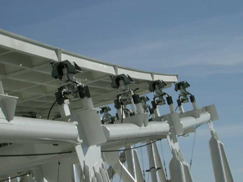
20 Another way to get more out of the telescope: receiver arrays Because of the complexity of the backend (e.g., filter bank) radio astronomers have traditionally been happy with just one receiver This gives a high degree of spectral multiplexing (many frequencies observed at the same time) but no spatial multiplexing (measures just one position at a time). A number of groups are developing receiver arrays these depend on the great computer power now available to carry out the backend Functions Here is one example: Supercam for the HHSMT
 Open mixer")

 SIS")

21 Mixer block (top) Open mixer block (center) SIS mixer and waveguide feed (lower left) SIS attached to low noise amplifier (lower right)

22 Power is concentrated onto the mixers with feedhorns: Here is a particularly efficient type, called a Winston Cone after its inventor:

 inside a 8 X 8")
23 Supercam uses a single local oscillator, so the power must be divided into 64 pixels using splitters (left) inside a 8 X 8 power divider (right)
 and field programmable gate arrays (FPGAs).")
 on overlapping segments of the IF data stream.")
. The electronics are surprisingly compact (left).")
24 The backend spectrometer is based on a filter bank concept. It makes use of very fast analog to digital convertors (ADCs) and field programmable gate arrays (FPGAs). The ADCs digitize the IF signal at 8 bits resolution (this preserves virtually all the information). The filter bank is implemented with Fast Fourier Transforms (FFTs) on overlapping segments of the IF data stream. The architecture is optimized for speed by dividing the data stream into blocks and making the FFTs operate on them with the most efficient spacing (termed ployphase). The electronics are surprisingly compact (left). Supercam goes onto the SMT as to the right and is currently going to visit APEX in Chile (altitude 5000 meters).
Submillimeter (continued)
") Submillimeter (continued) Dual Polarization, Sideband Separating Receiver Dual Mixer Unit The 12-m Receiver Here is where the receiver lives, at the telescope focus Receiver Performance T N (noise temperature)
Submillimeter (continued) Dual Polarization, Sideband Separating Receiver Dual Mixer Unit The 12-m Receiver Here is where the receiver lives, at the telescope focus Receiver Performance T N (noise temperature)
Coherent Receivers Principles Downconversion
 Coherent Receivers Principles Downconversion Heterodyne receivers mix signals of different frequency; if two such signals are added together, they beat against each other. The resulting signal contains
Introduction to Radio Astronomy!
 Introduction to Radio Astronomy! Sources of radio emission! Radio telescopes - collecting the radiation! Processing the radio signal! Radio telescope characteristics! Observing radio sources Sources of
A Crash Course in Radio Astronomy and Interferometry: 1. Basic Radio/mm Astronomy
 A Crash Course in Radio Astronomy and Interferometry: 1. Basic Radio/mm Astronomy James Di Francesco National Research Council of Canada North American ALMA Regional Center Victoria (thanks to S. Dougherty,
Submm and Radio. Chapter 8: Submillimeter and Radio Astronomy
 Chapter 8: Submillimeter and Radio Astronomy 8.1. Introduction The submillimeter and millimeter-wave regime roughly 0.2 mm to 3 mm - represents a transition between infrared and radio methods. Because
More Radio Astronomy
 More Radio Astronomy Radio Telescopes - Basic Design A radio telescope is composed of: - a radio reflector (the dish) - an antenna referred to as the feed on to which the radiation is focused - a radio
THEORY OF MEASUREMENTS
 THEORY OF MEASUREMENTS Brian Mason Fifth NAIC-NRAO School on Single-Dish Radio Astronomy Arecibo, PR July 2009 OUTLINE Antenna-Sky Coupling Noise the Radiometer Equation Minimum Tsys Performance measures
Astronomische Waarneemtechnieken (Astronomical Observing Techniques)
") Astronomische Waarneemtechnieken (Astronomical Observing Techniques) 7 th Lecture: 15 October 01 1. Introduction. Radio Emission 3. Observing 4. Antenna Technology 5. Receiver Technolgy 6. Back Ends 7.
Astronomische Waarneemtechnieken (Astronomical Observing Techniques) 7 th Lecture: 15 October 01 1. Introduction. Radio Emission 3. Observing 4. Antenna Technology 5. Receiver Technolgy 6. Back Ends 7.
of-the-art Terahertz astronomy detectors Dr. Ir. Gert de Lange
 State-of of-the-art Terahertz astronomy detectors Dr. Ir. Gert de Lange Outline Introduction SRON Origin, interest and challenges in (space) THz radiation Technology Heterodyne mixers Local oscillators
Signal Flow & Radiometer Equation. Aletha de Witt AVN-Newton Fund/DARA 2018 Observational & Technical Training HartRAO
 Signal Flow & Radiometer Equation Aletha de Witt AVN-Newton Fund/DARA 2018 Observational & Technical Training HartRAO Understanding Radio Waves The meaning of radio waves How radio waves are created -
Guide to observation planning with GREAT
 Guide to observation planning with GREAT G. Sandell GREAT is a heterodyne receiver designed to observe spectral lines in the THz region with high spectral resolution and sensitivity. Heterodyne receivers
Antennas & Receivers in Radio Astronomy
 Antennas & Receivers in Radio Astronomy Mark McKinnon Fifteenth Synthesis Imaging Workshop 1-8 June 2016 Purpose & Outline Purpose: describe how antenna elements can affect the quality of images produced
Detection Beyond 100µm Photon detectors no longer work ("shallow", i.e. low excitation energy, impurities only go out to equivalent of
 Detection Beyond 100µm Photon detectors no longer work ("shallow", i.e. low excitation energy, impurities only go out to equivalent of 100µm) A few tricks let them stretch a little further (like stressing)
Multiplying Interferometers
 Multiplying Interferometers L1 * L2 T + iv R1 * R2 T - iv L1 * R2 Q + iu R1 * L2 Q - iu Since each antenna can output both L and R polarization, all 4 Stokes parameters are simultaneously measured without
Sources classification
 Sources classification Radiometry relates to the measurement of the energy radiated by one or more sources in any region of the electromagnetic spectrum. As an antenna, a source, whose largest dimension
Observational Astronomy
 Observational Astronomy Instruments The telescope- instruments combination forms a tightly coupled system: Telescope = collecting photons and forming an image Instruments = registering and analyzing the
Heterodyne Receivers and Arrays
 Heterodyne Receivers and Arrays Gopal Narayanan gopal@astro.umass.edu Types of Detectors Incoherent Detection Bolometers Total Power Detection No phase information used primarily on single-dish antennas
MMA Memo 143: Report of the Receiver Committee for the MMA
 MMA Memo 143: Report of the Receiver Committee for the MMA 25 September, 1995 John Carlstrom Darrel Emerson Phil Jewell Tony Kerr Steve Padin John Payne Dick Plambeck Marian Pospieszalski Jack Welch, chair
Fundamentals of the GBT and Single-Dish Radio Telescopes Dr. Ron Maddalena
 Fundamentals of the GB and Single-Dish Radio elescopes Dr. Ron Maddalena March 2016 Associated Universities, Inc., 2016 National Radio Astronomy Observatory Green Bank, WV National Radio Astronomy Observatory
Detector Systems. Graeme Carrad
 Detector Systems Graeme Carrad November 2011 The Basic Structure of a typical Radio Telescope Antenna Receiver Conversion Digitiser Signal Processing / Correlator They are much the same CSIRO. Radiotelescope
Antennas and Receivers in Radio Astronomy
 Antennas and Receivers in Radio Astronomy Mark McKinnon Eleventh Synthesis Imaging Workshop Socorro, June 10-17, 2008 Outline 2 Context Types of antennas Antenna fundamentals Reflector antennas Mounts
Fundamentals of Radio Astronomy. Lyle Hoffman, Lafayette College ALFALFA Undergraduate Workshop Arecibo Observatory, 2008 Jan. 13
 Fundamentals of Radio Astronomy Lyle Hoffman, Lafayette College ALFALFA Undergraduate Workshop Arecibo Observatory, 2008 Jan. 13 Outline Sources in brief Radiotelescope components Radiotelescope characteristics
Sideband Smear: Sideband Separation with the ALMA 2SB and DSB Total Power Receivers
 and DSB Total Power Receivers SCI-00.00.00.00-001-A-PLA Version: A 2007-06-11 Prepared By: Organization Date Anthony J. Remijan NRAO A. Wootten T. Hunter J.M. Payne D.T. Emerson P.R. Jewell R.N. Martin
What does reciprocity mean
 Antennas Definition of antenna: A device for converting electromagnetic radiation in space into electrical currents in conductors or vice-versa. Radio telescopes are antennas Reciprocity says we can treat
Introduction to interferometry with bolometers: Bob Watson and Lucio Piccirillo
 Introduction to interferometry with bolometers: Bob Watson and Lucio Piccirillo Paris, 19 June 2008 Interferometry (heterodyne) In general we have i=1,...,n single dishes (with a single or dual receiver)
To print higher-resolution math symbols, click the Hi-Res Fonts for Printing button on the jsmath control panel.
 To print higher-resolution math symbols, click the Hi-Res Fonts for Printing button on the jsmath control panel. Radiometers Natural radio emission from the cosmic microwave background, discrete astronomical
17. Atmospheres and Instruments
 17. Atmospheres and Instruments Preliminaries 1. Diffraction limit: The diffraction limit on spatial resolution,, in radians 1.22 / d, where d is the diameter of the telescope and is the wavelength ( and
Astronomical Detectors. Lecture 3 Astronomy & Astrophysics Fall 2011
 Astronomical Detectors Lecture 3 Astronomy & Astrophysics Fall 2011 Detector Requirements Record incident photons that have been captured by the telescope. Intensity, Phase, Frequency, Polarization Difficulty
Antennas. Greg Taylor. University of New Mexico Spring Astronomy 423 at UNM Radio Astronomy
 Antennas Greg Taylor University of New Mexico Spring 2017 Astronomy 423 at UNM Radio Astronomy Outline 2 Fourier Transforms Interferometer block diagram Antenna fundamentals Types of antennas Antenna performance
The Cosmic Microwave Background Radiation B. Winstein, U of Chicago
 The Cosmic Microwave Background Radiation B. Winstein, U of Chicago Lecture #1 Lecture #2 What is it? How its anisotropies are generated? What Physics does it reveal? How it is measured. Lecture #3 Main
Antennas. Greg Taylor. University of New Mexico Spring Astronomy 423 at UNM Radio Astronomy
 Antennas Greg Taylor University of New Mexico Spring 2011 Astronomy 423 at UNM Radio Astronomy Radio Window 2 spans a wide range of λ and ν from λ ~ 0.33 mm to ~ 20 m! (ν = 1300 GHz to 15 MHz ) Outline
MMA Memo 161 Receiver Noise Temperature, the Quantum Noise Limit, and the Role of the Zero-Point Fluctuations *
 8th Int. Symp. on Space Terahertz Tech., March 25-27, 1997, pp. 101-111 MMA Memo 161 eceiver Noise Temperature, the Quantum Noise Limit, and the ole of the Zero-Point Fluctuations * A.. Kerr 1, M. J. Feldman
Antennas & Receivers in Radio Astronomy Mark McKinnon. Twelfth Synthesis Imaging Workshop 2010 June 8-15
 Antennas & Receivers in Radio Astronomy Mark McKinnon 2010 June 8-15 Outline Context Types of antennas Antenna fundamentals Reflector antennas Mounts Optics Antenna performance Aperture efficiency Pointing
Optical Signal Processing
 Optical Signal Processing ANTHONY VANDERLUGT North Carolina State University Raleigh, North Carolina A Wiley-Interscience Publication John Wiley & Sons, Inc. New York / Chichester / Brisbane / Toronto
CCDS. Lesson I. Wednesday, August 29, 12
 CCDS Lesson I CCD OPERATION The predecessor of the CCD was a device called the BUCKET BRIGADE DEVICE developed at the Phillips Research Labs The BBD was an analog delay line, made up of capacitors such
Technical Considerations: Nuts and Bolts Project Planning and Technical Justification
 Technical Considerations: Nuts and Bolts Project Planning and Technical Justification Atacama Large Millimeter/submillimeter Array Expanded Very Large Array Robert C. Byrd Green Bank Telescope Very Long
Chapter 3 OPTICAL SOURCES AND DETECTORS
 Chapter 3 OPTICAL SOURCES AND DETECTORS 3. Optical sources and Detectors 3.1 Introduction: The success of light wave communications and optical fiber sensors is due to the result of two technological breakthroughs.
Phased Array Feeds A new technology for wide-field radio astronomy
 Phased Array Feeds A new technology for wide-field radio astronomy Aidan Hotan ASKAP Project Scientist 29 th September 2017 CSIRO ASTRONOMY AND SPACE SCIENCE Outline Review of radio astronomy concepts
Interference [Hecht Ch. 9]
![Interference [Hecht Ch. 9]](/thumbs/79/79365345.jpg "Interference [Hecht Ch. 9]") Interference [Hecht Ch. 9] Note: Read Ch. 3 & 7 E&M Waves and Superposition of Waves and Meet with TAs and/or Dr. Lai if necessary. General Consideration 1 2 Amplitude Splitting Interferometers If a lightwave
Interference [Hecht Ch. 9] Note: Read Ch. 3 & 7 E&M Waves and Superposition of Waves and Meet with TAs and/or Dr. Lai if necessary. General Consideration 1 2 Amplitude Splitting Interferometers If a lightwave
NIR SPECTROSCOPY Instruments
 What is needed to construct a NIR instrument? NIR SPECTROSCOPY Instruments Umeå 2006-04-10 Bo Karlberg light source dispersive unit (monochromator) detector (Fibres) (bsorbance/reflectance-standard) The
Based on lectures by Bernhard Brandl
 Astronomische Waarneemtechnieken (Astronomical Observing Techniques) Based on lectures by Bernhard Brandl Lecture 10: Detectors 2 1. CCD Operation 2. CCD Data Reduction 3. CMOS devices 4. IR Arrays 5.
Sub-Millimeter RF Receiver. Sub-Millimeter 19Receiver. balanced using Polarization Vectors. Intrel Service Company
 Sub-Millimeter RF Receiver balanced using Polarization Vectors Intrel Service Company iscmail@intrel.com Sub-Millimeter Week of RF 19Receiver August 2012 Copyright Intrel Service Company 2012 Some Rights
Richard Dodson 1/28/2014 NARIT-KASI Winter School
 Goals: Technical introduction very short So what to cover? Things which are essential: How radio power is received - I How an interferometer works -II Antenna Fundamentals Black Body Radiation Brightness
Holography Transmitter Design Bill Shillue 2000-Oct-03
 Holography Transmitter Design Bill Shillue 2000-Oct-03 Planned Photonic Reference Distribution for Test Interferometer The transmitter for the holography receiver is made up mostly of parts that are already
Fundamentals of Radio Interferometry
 Fundamentals of Radio Interferometry Rick Perley, NRAO/Socorro ATNF Radio Astronomy School Narrabri, NSW 29 Sept. 03 Oct. 2014 Topics Introduction: Sensors, Antennas, Brightness, Power Quasi-Monochromatic
Photonic Signals. and Systems. An Introduction. NabeelA.Riza/Ph.D. Department of Electrical and Electronic Engineering University College Cork
 Photonic Signals and Systems An Introduction NabeelA.Riza/Ph.D. Department of Electrical and Electronic Engineering University College Cork Cork, Ireland New York Chicago San Francisco Lisbon London Madrid
Receiver Design for Passive Millimeter Wave (PMMW) Imaging
 Imaging") Introduction Receiver Design for Passive Millimeter Wave (PMMW) Imaging Millimeter Wave Systems, LLC Passive Millimeter Wave (PMMW) sensors are used for remote sensing and security applications. They rely
Introduction Receiver Design for Passive Millimeter Wave (PMMW) Imaging Millimeter Wave Systems, LLC Passive Millimeter Wave (PMMW) sensors are used for remote sensing and security applications. They rely
Introduction to Radio Astronomy. Richard Porcas Max-Planck-Institut fuer Radioastronomie, Bonn
 Introduction to Radio Astronomy Richard Porcas Max-Planck-Institut fuer Radioastronomie, Bonn 1 Contents Radio Waves Radio Emission Processes Radio Noise Radio source names and catalogues Radio telescopes
Chapter 3. Instrumentation. 3.1 Telescope Site Layout. 3.2 Telescope Optics
 Chapter 3 Instrumentation 3.1 Telescope Site Layout The 12m is located on the southwest ridge of Kitt Peak, about two miles below the top of the mountain. Other telescopes on the southwest ridge are the
Phased Array Feeds & Primary Beams
 Phased Array Feeds & Primary Beams Aidan Hotan ASKAP Deputy Project Scientist 3 rd October 2014 CSIRO ASTRONOMY AND SPACE SCIENCE Outline Review of parabolic (dish) antennas. Focal plane response to a
Important performance parameters when considering lasers for holographic applications
 Important performance parameters when considering lasers for holographic applications E.K. Illy*, H. Karlsson & G. Elgcrona. Cobolt AB, a part of HÜBNER Photonics, Vretenvägen 13, 17154, Stockholm, Sweden.
TDI Imaging: An Efficient AOI and AXI Tool
 TDI Imaging: An Efficient AOI and AXI Tool Yakov Bulayev Hamamatsu Corporation Bridgewater, New Jersey Abstract As a result of heightened requirements for quality, integrity and reliability of electronic
Noise generators. Spatial Combining of Multiple Microwave Noise Radiators NOISE ARRAY. This article reports on. experiments to increase the
 From April 2008 High Frequency Electronics Copyright 2008 Summit Technical Media LLC Spatial Combining of Multiple Microwave Noise Radiators By Jiri Polivka Spacek Labs Inc. Noise generators This article
suppose we observed a 10 Jy calibrator with CARMA for 1 year, 24 hrs/day how much energy would we collect? S ηa Δν t
 3 hardware lectures 1. receivers - SIS mixers, amplifiers, cryogenics, dewars, calibration; followed by antenna tour; later, take apart a 6-m dewar 2. correlator (James Lamb) 3. local oscillator system
High Contrast Imaging
 High Contrast Imaging Suppressing diffraction (rings and other patterns) Doing this without losing light Suppressing scattered light Doing THIS without losing light Diffraction rings arise from the abrupt
Submillimeter Instrumentation. Photo-detectors are no longer effective Submm astronomers use bolometers and heterodyne receivers.
 Submillimeter Instrumentation Photo-detectors are no longer effective Submm astronomers use bolometers and heterodyne receivers. Bolometers A bolometer consists of an absorber (efficiency ) attached to
Lecture 08. Fundamentals of Lidar Remote Sensing (6)
") Lecture 08. Fundamentals of Lidar Remote Sensing (6) Basic Lidar Architecture q Basic Lidar Architecture q Configurations vs. Arrangements q Transceiver with HOE q A real example: STAR Na Doppler Lidar
Lecture 08. Fundamentals of Lidar Remote Sensing (6) Basic Lidar Architecture q Basic Lidar Architecture q Configurations vs. Arrangements q Transceiver with HOE q A real example: STAR Na Doppler Lidar
Dartmouth College LF-HF Receiver May 10, 1996
 AGO Field Manual Dartmouth College LF-HF Receiver May 10, 1996 1 Introduction Many studies of radiowave propagation have been performed in the LF/MF/HF radio bands, but relatively few systematic surveys
A 3 GHz instantaneous bandwidth Acousto- Optical spectrometer with 1 MHz resolution
 A 3 GHz instantaneous bandwidth Acousto- Optical spectrometer with 1 MHz resolution M. Olbrich, V. Mittenzwei, O. Siebertz, F. Schmülling, and R. Schieder KOSMA, I. Physikalisches Institut, Universität
OPTICS OF SINGLE BEAM, DUAL BEAM & ARRAY RECEIVERS ON LARGE TELESCOPES J A M E S W L A M B, C A L T E C H
 OPTICS OF SINGLE BEAM, DUAL BEAM & ARRAY RECEIVERS ON LARGE TELESCOPES J A M E S W L A M B, C A L T E C H OUTLINE Antenna optics Aberrations Diffraction Single feeds Types of feed Bandwidth Imaging feeds
1170 LIDAR / Atmospheric Sounding Introduction
 1170 LIDAR / Atmospheric Sounding Introduction a distant large telescope for the receiver. In this configuration, now known as bistatic, the range of the scattering can be determined by geometry. In the
Period 3 Solutions: Electromagnetic Waves Radiant Energy II
 Period 3 Solutions: Electromagnetic Waves Radiant Energy II 3.1 Applications of the Quantum Model of Radiant Energy 1) Photon Absorption and Emission 12/29/04 The diagrams below illustrate an atomic nucleus
Instruction manual and data sheet ipca h
 1/15 instruction manual ipca-21-05-1000-800-h Instruction manual and data sheet ipca-21-05-1000-800-h Broad area interdigital photoconductive THz antenna with microlens array and hyperhemispherical silicon
Pupil Planes versus Image Planes Comparison of beam combining concepts
 Pupil Planes versus Image Planes Comparison of beam combining concepts John Young University of Cambridge 27 July 2006 Pupil planes versus Image planes 1 Aims of this presentation Beam combiner functions
Where detectors are used in science & technology
 Lecture 9 Outline Role of detectors Photomultiplier tubes (photoemission) Modulation transfer function Photoconductive detector physics Detector architecture Where detectors are used in science & technology
Lab Exercises. Exercise 1. Objective. Theory. Lab Exercises
 Lab Exercises Exercise 1 Objective! Study the generation of differential binary signal.! Study the differential PSK modulation.! Study the differential PSK demodulation. Lab Exercises Theory Carrier and
In the name of God, the most merciful Electromagnetic Radiation Measurement
 In the name of God, the most merciful Electromagnetic Radiation Measurement In these slides, many figures have been taken from the Internet during my search in Google. Due to the lack of space and diversity
How Does One Obtain Spectral/Imaging Information! "
 How Does One Obtain Spectral/Imaging Information! How do we measure the position, energy, and arrival time of! an X-ray photon?! " What we observe depends on the instruments that one observes with!" In
Fundamentals of Radio Interferometry
 Fundamentals of Radio Interferometry Rick Perley, NRAO/Socorro Fourteenth NRAO Synthesis Imaging Summer School Socorro, NM Topics Why Interferometry? The Single Dish as an interferometer The Basic Interferometer
The FTNIR Myths... Misinformation or Truth
 The FTNIR Myths... Misinformation or Truth Recently we have heard from potential customers that they have been told that FTNIR instruments are inferior to dispersive or monochromator based NIR instruments.
Optics and Lasers. Matt Young. Including Fibers and Optical Waveguides
 Matt Young Optics and Lasers Including Fibers and Optical Waveguides Fourth Revised Edition With 188 Figures Springer-Verlag Berlin Heidelberg New York London Paris Tokyo Hong Kong Barcelona Budapest Contents
Reflectors vs. Refractors
 1 Telescope Types - Telescopes collect and concentrate light (which can then be magnified, dispersed as a spectrum, etc). - In the end it is the collecting area that counts. - There are two primary telescope
Detection of the mm-wave radiation using a low-cost LWIR microbolometer camera from a multiplied Schottky diode based source
 Detection of the mm-wave radiation using a low-cost LWIR microbolometer camera from a multiplied Schottky diode based source Basak Kebapci 1, Firat Tankut 2, Hakan Altan 3, and Tayfun Akin 1,2,4 1 METU-MEMS
Gerhard K. Ackermann and Jurgen Eichler. Holography. A Practical Approach BICENTENNIAL. WILEY-VCH Verlag GmbH & Co. KGaA
 Gerhard K. Ackermann and Jurgen Eichler Holography A Practical Approach BICENTENNIAL BICENTENNIAL WILEY-VCH Verlag GmbH & Co. KGaA Contents Preface XVII Part 1 Fundamentals of Holography 1 1 Introduction
Phased Array Feeds A new technology for multi-beam radio astronomy
 Phased Array Feeds A new technology for multi-beam radio astronomy Aidan Hotan ASKAP Deputy Project Scientist 2 nd October 2015 CSIRO ASTRONOMY AND SPACE SCIENCE Outline Review of radio astronomy concepts.
Telescopes and their configurations. Quick review at the GO level
 Telescopes and their configurations Quick review at the GO level Refraction & Reflection Light travels slower in denser material Speed depends on wavelength Image Formation real Focal Length (f) : Distance
Antenna Fundamentals Basics antenna theory and concepts
 Antenna Fundamentals Basics antenna theory and concepts M. Haridim Brno University of Technology, Brno February 2017 1 Topics What is antenna Antenna types Antenna parameters: radiation pattern, directivity,
Introduction to DSTV Dish Observations. Alet de Witt AVN Technical Training 2016
 Introduction to DSTV Dish Observations Alet de Witt AVN Technical Training 2016 Outline Theory: - Radio Waves - Radio Telescope Antennas - Angular Sizes - Brightness Temperature and Antenna Temperature
Introduction to the operating principles of the HyperFine spectrometer
 Introduction to the operating principles of the HyperFine spectrometer LightMachinery Inc., 80 Colonnade Road North, Ottawa ON Canada A spectrometer is an optical instrument designed to split light into
Characterization of Chirped volume bragg grating (CVBG)
") Characterization of Chirped volume bragg grating (CVBG) Sobhy Kholaif September 7, 017 1 Laser pulses Ultrashort laser pulses have extremely short pulse duration. When the pulse duration is less than picoseconds
Characterization of Chirped volume bragg grating (CVBG) Sobhy Kholaif September 7, 017 1 Laser pulses Ultrashort laser pulses have extremely short pulse duration. When the pulse duration is less than picoseconds
EE119 Introduction to Optical Engineering Spring 2003 Final Exam. Name:
 EE119 Introduction to Optical Engineering Spring 2003 Final Exam Name: SID: CLOSED BOOK. THREE 8 1/2 X 11 SHEETS OF NOTES, AND SCIENTIFIC POCKET CALCULATOR PERMITTED. TIME ALLOTTED: 180 MINUTES Fundamental
Exam 4. Name: Class: Date: Multiple Choice Identify the choice that best completes the statement or answers the question.
 Name: Class: Date: Exam 4 Multiple Choice Identify the choice that best completes the statement or answers the question. 1. Mirages are a result of which physical phenomena a. interference c. reflection
instruments Solar Physics course lecture 3 May 4, 2010 Frans Snik BBL 415 (710)
") Solar Physics course lecture 3 May 4, 2010 Frans Snik BBL 415 (710) f.snik@astro.uu.nl www.astro.uu.nl/~snik info from photons spatial (x,y) temporal (t) spectral (λ) polarization ( ) usually photon starved
Solar Physics course lecture 3 May 4, 2010 Frans Snik BBL 415 (710) f.snik@astro.uu.nl www.astro.uu.nl/~snik info from photons spatial (x,y) temporal (t) spectral (λ) polarization ( ) usually photon starved
M^i»' fcsf " s«tar p-o^iic rsieaajg}
 Serial No. 605.251 Filing Date 13 February 1996 Inventor Tae K. Oh M^i»' fcsf " s«tar p-o^iic rsieaajg} NOTICE The above identified patent application is available for licensing. Requests for information
DRAFT. Enhanced Image Rejection in Receivers with Sideband-Separating Mixers. A. R. Kerr 21 December 2006
 EnhancedImageRejection03.wpd DRAFT Enhanced Image Rejection in Receivers with Sideband-Separating ixers A. R. Kerr 2 December 2006 ABSTRACT: The finite image rejection of a spectrometer using a sideband-separating
COHERENT DETECTION AND SIS MIXERS
 COHERENT DETECTION AND SIS MIXERS J. Zmuidzinas Division of Physics, Mathematics, and Astronomy California Institute of Technology, 320 47, Pasadena, CA 91125 ABSTRACT Submillimeter spectroscopy is a unique
IF/LO Systems for Single Dish Radio Astronomy cm-wave Receivers
 IF/LO Systems for Single Dish Radio Astronomy cm-wave Receivers Lisa Wray, Arecibo Observatory NRAO/NAIC Single Dish Summer School August 2003 Introduction to Receivers a specialized class of microwave
Recent progress and future development of Nobeyama 45-m Telescope
 Recent progress and future development of Nobeyama 45-m Telescope Masao Saito: Director of Nobeyama Radio Observatory Tetsuhiro Minamidani: Nobeyama Radio Observatory Outline Nobeyama 45-m Telescope Recent
Lab Report 3: Speckle Interferometry LIN PEI-YING, BAIG JOVERIA
 Lab Report 3: Speckle Interferometry LIN PEI-YING, BAIG JOVERIA Abstract: Speckle interferometry (SI) has become a complete technique over the past couple of years and is widely used in many branches of
Isolator-Free 840-nm Broadband SLEDs for High-Resolution OCT
 Isolator-Free 840-nm Broadband SLEDs for High-Resolution OCT M. Duelk *, V. Laino, P. Navaretti, R. Rezzonico, C. Armistead, C. Vélez EXALOS AG, Wagistrasse 21, CH-8952 Schlieren, Switzerland ABSTRACT
Outline / Wireless Networks and Applications Lecture 3: Physical Layer Signals, Modulation, Multiplexing. Cartoon View 1 A Wave of Energy
 Outline 18-452/18-750 Wireless Networks and Applications Lecture 3: Physical Layer Signals, Modulation, Multiplexing Peter Steenkiste Carnegie Mellon University Spring Semester 2017 http://www.cs.cmu.edu/~prs/wirelesss17/
IF/LO Systems for Single Dish Radio Astronomy Centimeter Wave Receivers
 IF/LO Systems for Single Dish Radio Astronomy Centimeter Wave Receivers Lisa Wray NAIC, Arecibo Observatory Abstract. Radio astronomy receivers designed to detect electromagnetic waves from faint celestial
ASD and Speckle Interferometry. Dave Rowe, CTO, PlaneWave Instruments
 ASD and Speckle Interferometry Dave Rowe, CTO, PlaneWave Instruments Part 1: Modeling the Astronomical Image Static Dynamic Stochastic Start with Object, add Diffraction and Telescope Aberrations add Atmospheric
A 350 GHz SIS Imaging Module for. the JCMT Heterodyne Array. T.M. Klapwijk 3. Abstract
 A 350 GHz SIS Imaging Module for the JCMT Heterodyne Array Receiver Programme (HARP) J. Leech 1, S. Withington 1, G. Yassin 1, H. Smith 1, B.D. Jackson 2, J.R. Gao 2, T.M. Klapwijk 3. 1 Cavendish Laboratory,
Module 19 : WDM Components
 Module 19 : WDM Components Lecture : WDM Components - I Part - I Objectives In this lecture you will learn the following WDM Components Optical Couplers Optical Amplifiers Multiplexers (MUX) Insertion
Infrared Single Shot Diagnostics for the Longitudinal. Profile of the Electron Bunches at FLASH. Disputation
 Infrared Single Shot Diagnostics for the Longitudinal Profile of the Electron Bunches at FLASH Disputation Hossein Delsim-Hashemi Tuesday 22 July 2008 7/23/2008 2/ 35 Introduction m eb c 2 3 2 γ ω = +
Luminous Equivalent of Radiation
 Intensity vs λ Luminous Equivalent of Radiation When the spectral power (p(λ) for GaP-ZnO diode has a peak at 0.69µm) is combined with the eye-sensitivity curve a peak response at 0.65µm is obtained with
AGRON / E E / MTEOR 518 Laboratory
 AGRON / E E / MTEOR 518 Laboratory Brian Hornbuckle, Nolan Jessen, and John Basart April 5, 2018 1 Objectives In this laboratory you will: 1. identify the main components of a ground based microwave radiometer
GRENOUILLE.
 GRENOUILLE Measuring ultrashort laser pulses the shortest events ever created has always been a challenge. For many years, it was possible to create ultrashort pulses, but not to measure them. Techniques
Detectors for microscopy - CCDs, APDs and PMTs. Antonia Göhler. Nov 2014
 Detectors for microscopy - CCDs, APDs and PMTs Antonia Göhler Nov 2014 Detectors/Sensors in general are devices that detect events or changes in quantities (intensities) and provide a corresponding output,