The Cosmic Microwave Background Radiation B. Winstein, U of Chicago
|
|
|
- Sherman Watts
- 6 years ago
- Views:
Transcription
1 The Cosmic Microwave Background Radiation B. Winstein, U of Chicago Lecture #1 Lecture #2 What is it? How its anisotropies are generated? What Physics does it reveal? How it is measured. Lecture #3 Main thrusts for the next decade.
2 Lecture #2: Measuring the Cosmic Microwave Background Radio telescopes Receiver Types Sources of Noise Sensitivities Observing trade-offs and strategies From raw data to power spectra

3 Looking at a Point on the Sky R.H. Dicke and colleagues, mid 1940s
4 Elements of a Radio Telescope Antenna Amplifier Filter Power Meter Amplifier
5 Elements of a Radio Telescope Antenna Amplifier low-noise, high bandwidth Filter selects ν Power Meter measures <E 2 > Amplifier low frequency (DC)

6 Antenna Pattern Near side lobes Main beam Diffraction limit: AΩ=λ 2 A: collecting area Ω: beam solid angle λ:wavelength Far side lobes
7 CMB Flux Planck Spectrum: B ν = 2hν 3 c 2 1 e hν / kt 1 W / m2 / str/ Hz Example: beam FWHM = 8 0 ; beam area = 8 cm 2 ν 0 = 90 GHz; ν = 10 GHz The CMB flux on the horn is then: 2.5 x Watts
8 Radiation Detection Coherent Detectors (phase preserving) [Bolometric Detectors tomorrow]
9 Signal Level from the CMB 3 0 radiation Gain Antenna Amplifier Filter low-noise, high bandwidth selects ν 1mV/uW Power Meter measures <E 2 > 100 Amplifier low frequency (DC) 10mV
10 Heterodyne Receivers With coherent receivers one can mix down the radio frequency to an intermediate frequency (IF) Eg ( GHz) x 82 GHz = 2-18 GHz Signal can be manipulated on coax Amplifiers are lower noise

11 CAPMAP: Chicago, Miami, Princeton Multistage RF amplification 1st stage most important (like photomultipliers)
 Power")
12 IF signals on coax (2-18 GHz) Power detector

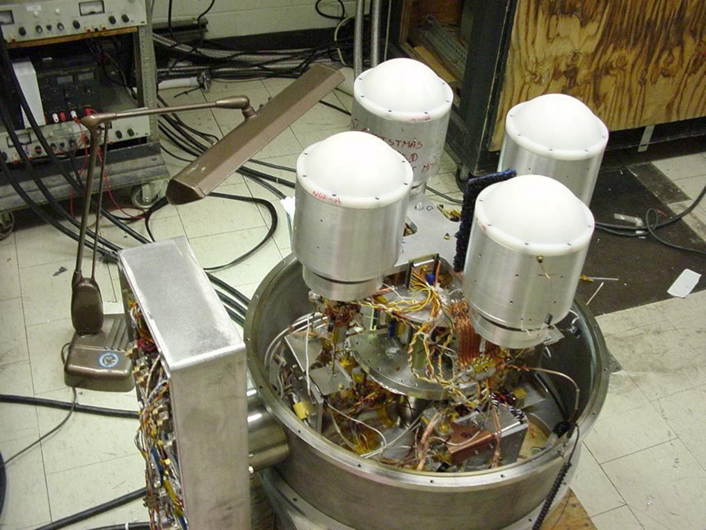
13 CAPMAP Receivers horn & lens MMIC HEMT amplifier Warm section LO chain & power amp IF section Figures by M. Hedman
14

15 Crawford Hill, NJ 7 meter radio telescope

16
17 Dicke Paper
18 Atmospheric Noise The Atmosphere will both absorb incident radiation and emit its own radiation These are connected by Kirchoff s Law T D = T S e τ + T C (1 e τ ) T S T C
19 Atmospheric Noise continued T D = T S e τ + T C (1 e τ ) Optical Depth τ 0 Detector Signal T D T S 0.2 T C 45 K (T C = 250 K)
20 Atmospheric Absorption 90 GHZ
21 Amplifier Noise Ideal amplifier: power generated (with NO input) depends on its (physical) temperature T and ν p = hν dν ktdν e hν / kt 1 State-of-the-art 90 GHz amplifiers: T (physical) = 10 K T (noise) = 45 K
22 Components of the Signal 3 K from the CMB 45 K from Amplifier Noise 45 K from Atmospheric Noise 100 K system temperature
23 Sensitivity of the Radiometer How well can we measure the temperature at a point on the sky? T = T sys ν t obs = 1mk sec in our case Where does this come from?
24 Radiometer Sensitivity a la Dicke Antenna Noise as a pulse train: 1/ ν ν is receiver bandwidth T system = 100 K T signal = 1 µk = 10-8 of system Temp. need pulses Take ν = 10 GHz Count for 10 6 seconds for 1σ Challenge to keep systematics (amplifier drifts, atmospheric noise, etc.) under control during this large integration time.
25 Calibration of Radiometers Shine various BBs on the system and measure the response, check linearity, etc. Allows expressing signal levels in terms of equivalent temperatures In the field, LN 2, the moon, and a few of the planets are useful for this purpose
26 Astronomical Effects Planets Galactic Emission Synchrotron Bremstrahlung Dust Extra-galactic sources Radio sources Use multiple frequencies Pick quiet regions Hot gas in Galaxy clusters (SZ effect) Gravitational Lensing (Lecture 3)

27
28 Instrumental Effects Amplifier Drifts Use Dicke switching Electrical Grounding Critical with such high gains Mechanical pickup telescope motion; mechanical refrigerator Optics/ground pickup shield radiometer from the 300K ground Thermal regulation Gains vary with temperature
29 Still looking at one spot Power Power with gain drift Change in power Signal change Change in power Sensitivity limit due To Gain drifts: W = k(t 1 + T sys )G ν W + W = k(t 1 + T sys )(G + G) ν W = G νk(t 1 + T sys ) W + W = k(t 1 + T + T sys )G ν W = G νk T T = G T sys G
30 Dicke Switching/Chopping Power at 1 Power at 2 difference Gain drift Signal change W 1 = k(t 1 + T sys )G ν W 2 = k(t 2 + T sys )G ν W W 1 W 2 = k(t 1 T 2 )G ν W + W = k(t 1 T 2 )(G + G) ν W + W = k(t 1 T 2 + T)(G) ν Sensitivity limit due To Gain drifts: T T sys = T 1 T 2 T sys G G
31 8 seconds of data (0.01 sec samples) unswitched switched
32 15 minutes of bad data
33 15 minutes of good data

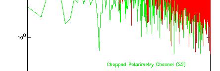
34 1/f noise Noise Powers (amplifier+atmosphere) unswitched switched
35 Power Spectra Sensitivity: Cosmic variance C l C l = 2 2l +1
36 Cosmic Variance + noise C l C l = 2 4πw 1+ 2l +1 C l where w : total experimental weight [µk 2 ]
37 Cosmic Variance + noise + finite sky C l C l = 2 2l πw f sky f sky C l where f sky w : fraction of the sky observed : total experimental weight [µk 2 ]
38 Cosmic Variance + noise + finite sky + finite beam size C l C l = 2 2l +1 1 f sky + 4πw C l f sky e l 2 σ b 2 where f sky w : fraction of the sky observed : total experimental weight [µk 2 ] σ b : beam rms
39 Effect of Finite Beam Size MAP beam: 0.24 deg. CAPMAP beam: 0.05 deg.
40 Choosing the Observing Strategy Depends on l-coverage desired Depends on sensitivity desired Frequent switching desired Frequent redundancies Multiple time scales
41
 Sample variance Detector")
42 SENSITIVITY SIMULATIONS (using CfCP 32-node cluster) Sample variance Detector noise
43 Data Processing Calibrate; de-glitch time series Bin in sky coordinates Offset removal Mean, slope, quadratic? Make a map Pixels will be correlated Run likelihood for power in l-bands (C l s) Capmap: inversion of 5760x5760 matrix Run likelihood for cosmological params.
44 !Radiometer Offsets! Residual Structure, µk vs. azimuth pixel

45 Modes with High S/N
46 Modes with High S/N Mean removed
47
48 Final Check: Null Tests Create maps that should have no signal First 1/2 of data minus second 1/2 Alternate signs on samples in each pixel Day minus night
49 The Cosmic Microwave Background Radiation B. Winstein, U of Chicago Lecture #3 Main thrusts for the next decade.
More Radio Astronomy
 More Radio Astronomy Radio Telescopes - Basic Design A radio telescope is composed of: - a radio reflector (the dish) - an antenna referred to as the feed on to which the radiation is focused - a radio
A Crash Course in Radio Astronomy and Interferometry: 1. Basic Radio/mm Astronomy
 A Crash Course in Radio Astronomy and Interferometry: 1. Basic Radio/mm Astronomy James Di Francesco National Research Council of Canada North American ALMA Regional Center Victoria (thanks to S. Dougherty,
Introduction to Radio Astronomy!
 Introduction to Radio Astronomy! Sources of radio emission! Radio telescopes - collecting the radiation! Processing the radio signal! Radio telescope characteristics! Observing radio sources Sources of
Introduction to DSTV Dish Observations. Alet de Witt AVN Technical Training 2016
 Introduction to DSTV Dish Observations Alet de Witt AVN Technical Training 2016 Outline Theory: - Radio Waves - Radio Telescope Antennas - Angular Sizes - Brightness Temperature and Antenna Temperature
The Q/U Imaging ExperimenT (QUIET) receivers Coherent Polarimeter Arrays at 40 and 90 GHz
 receivers Coherent Polarimeter Arrays at 40 and 90 GHz") The Q/U Imaging ExperimenT (QUIET) receivers Coherent Polarimeter Arrays at 40 and 90 GHz Dorothea Samtleben, Max-Planck-Institut für Radioastronomie, Bonn Universe becomes transparent => Release of Cosmic
The Q/U Imaging ExperimenT (QUIET) receivers Coherent Polarimeter Arrays at 40 and 90 GHz Dorothea Samtleben, Max-Planck-Institut für Radioastronomie, Bonn Universe becomes transparent => Release of Cosmic
CAPMAP Control of Systematic Effects
 CAPMAP Control of Systematic Effects Jeff McMahon Kavli Institute for Cosmological Physics University of Chicago Inflation Probe Systematics Workshop Annapolis, MD, July 28-30, 2008 The CAPMAP Collaboration
Sources classification
 Sources classification Radiometry relates to the measurement of the energy radiated by one or more sources in any region of the electromagnetic spectrum. As an antenna, a source, whose largest dimension
DESIGN AND CONSTRUCTION OF THE COSMIC MICROWAVE RADIOMETER
 DESIGN AND CONSTRUCTION OF THE COSMIC MICROWAVE RADIOMETER Jack Gelfand PhD Portland, ME USA Jack.gelfand@oswego.edu HOW CAN I DETECT THE COSMIC MICROWAVE BACKGROUND? Difficult to find the important design
Fundamentals of Radio Astronomy. Lyle Hoffman, Lafayette College ALFALFA Undergraduate Workshop Arecibo Observatory, 2008 Jan. 13
 Fundamentals of Radio Astronomy Lyle Hoffman, Lafayette College ALFALFA Undergraduate Workshop Arecibo Observatory, 2008 Jan. 13 Outline Sources in brief Radiotelescope components Radiotelescope characteristics
Introduction to Radio Astronomy. Richard Porcas Max-Planck-Institut fuer Radioastronomie, Bonn
 Introduction to Radio Astronomy Richard Porcas Max-Planck-Institut fuer Radioastronomie, Bonn 1 Contents Radio Waves Radio Emission Processes Radio Noise Radio source names and catalogues Radio telescopes
To print higher-resolution math symbols, click the Hi-Res Fonts for Printing button on the jsmath control panel.
 To print higher-resolution math symbols, click the Hi-Res Fonts for Printing button on the jsmath control panel. Radiometers Natural radio emission from the cosmic microwave background, discrete astronomical
Receiver Design for Passive Millimeter Wave (PMMW) Imaging
 Imaging") Introduction Receiver Design for Passive Millimeter Wave (PMMW) Imaging Millimeter Wave Systems, LLC Passive Millimeter Wave (PMMW) sensors are used for remote sensing and security applications. They rely
Introduction Receiver Design for Passive Millimeter Wave (PMMW) Imaging Millimeter Wave Systems, LLC Passive Millimeter Wave (PMMW) sensors are used for remote sensing and security applications. They rely
Signal Flow & Radiometer Equation. Aletha de Witt AVN-Newton Fund/DARA 2018 Observational & Technical Training HartRAO
 Signal Flow & Radiometer Equation Aletha de Witt AVN-Newton Fund/DARA 2018 Observational & Technical Training HartRAO Understanding Radio Waves The meaning of radio waves How radio waves are created -
Guide to observation planning with GREAT
 Guide to observation planning with GREAT G. Sandell GREAT is a heterodyne receiver designed to observe spectral lines in the THz region with high spectral resolution and sensitivity. Heterodyne receivers
AGRON / E E / MTEOR 518 Laboratory
 AGRON / E E / MTEOR 518 Laboratory Brian Hornbuckle, Nolan Jessen, and John Basart April 5, 2018 1 Objectives In this laboratory you will: 1. identify the main components of a ground based microwave radiometer
Multiplying Interferometers
 Multiplying Interferometers L1 * L2 T + iv R1 * R2 T - iv L1 * R2 Q + iu R1 * L2 Q - iu Since each antenna can output both L and R polarization, all 4 Stokes parameters are simultaneously measured without
Submillimeter (continued)
") Submillimeter (continued) Dual Polarization, Sideband Separating Receiver Dual Mixer Unit The 12-m Receiver Here is where the receiver lives, at the telescope focus Receiver Performance T N (noise temperature)
Submillimeter (continued) Dual Polarization, Sideband Separating Receiver Dual Mixer Unit The 12-m Receiver Here is where the receiver lives, at the telescope focus Receiver Performance T N (noise temperature)
Low frequency noise measurements in direct detection radiometers
 Low frequency noise measurements in direct detection radiometers E. Artal, B. Aja, J. Cagigas, J.L. Cano, L. de la Fuente, A. Pérez, E. Villa Universidad de Cantabria, Santander (Spain) Receiver Gain Stability
Receiver Performance and Comparison of Incoherent (bolometer) and Coherent (receiver) detection
 and Coherent (receiver) detection") At ev gap /h the photons have sufficient energy to break the Cooper pairs and the SIS performance degrades. Receiver Performance and Comparison of Incoherent (bolometer) and Coherent (receiver) detection
At ev gap /h the photons have sufficient energy to break the Cooper pairs and the SIS performance degrades. Receiver Performance and Comparison of Incoherent (bolometer) and Coherent (receiver) detection
suppose we observed a 10 Jy calibrator with CARMA for 1 year, 24 hrs/day how much energy would we collect? S ηa Δν t
 3 hardware lectures 1. receivers - SIS mixers, amplifiers, cryogenics, dewars, calibration; followed by antenna tour; later, take apart a 6-m dewar 2. correlator (James Lamb) 3. local oscillator system
A Quick Review. Spectral Line Calibration Techniques with Single Dish Telescopes. The Rayleigh-Jeans Approximation. Antenna Temperature
 Spectral Line Calibration Techniques with Single Dish Telescopes A Quick Review K. O Neil NRAO - GB A Quick Review A Quick Review The Rayleigh-Jeans Approximation Antenna Temperature Planck Law for Blackbody
THEORY OF MEASUREMENTS
 THEORY OF MEASUREMENTS Brian Mason Fifth NAIC-NRAO School on Single-Dish Radio Astronomy Arecibo, PR July 2009 OUTLINE Antenna-Sky Coupling Noise the Radiometer Equation Minimum Tsys Performance measures
and GHz. ECE Radiometer. Technical Description and User Manual
 E-mail: sales@elva-1.com http://www.elva-1.com 26.5-40 and 76.5-90 GHz ECE Radiometer Technical Description and User Manual November 2008 Contents 1. Introduction... 3 2. Parameters and specifications...
Detectors. RIT Course Number Lecture Noise
 Detectors RIT Course Number 1051-465 Lecture Noise 1 Aims for this lecture learn to calculate signal-to-noise ratio describe processes that add noise to a detector signal give examples of how to combat
AVN Training HartRAO 2016
 AVN Training HartRAO 2016 Microwave 1 Overview Introduction to basic components used in microwave receivers. Performance characteristics of these components. Assembly of components into a complete microwave
Coherent Receivers Principles Downconversion
 Coherent Receivers Principles Downconversion Heterodyne receivers mix signals of different frequency; if two such signals are added together, they beat against each other. The resulting signal contains
The WVR at Effelsberg. Thomas Krichbaum
 The WVR at Effelsberg Alan Roy Ute Teuber Helge Rottmann Thomas Krichbaum Reinhard Keller Dave Graham Walter Alef The Scanning 18-26 GHz WVR for Effelsberg ν = 18.5 GHz to 26.0 GHz Δν = 900 MHz Channels
Microwave Radiometry Laboratory Experiment
 Microwave Radiometry Laboratory Experiment JEFFREY D. DUDA Iowa State University Department of Geologic and Atmospheric Sciences ABSTRACT A laboratory experiment involving the use of a microwave radiometer
Fundamentals of the GBT and Single-Dish Radio Telescopes Dr. Ron Maddalena
 Fundamentals of the GB and Single-Dish Radio elescopes Dr. Ron Maddalena March 2016 Associated Universities, Inc., 2016 National Radio Astronomy Observatory Green Bank, WV National Radio Astronomy Observatory
Detector Systems. Graeme Carrad
 Detector Systems Graeme Carrad November 2011 The Basic Structure of a typical Radio Telescope Antenna Receiver Conversion Digitiser Signal Processing / Correlator They are much the same CSIRO. Radiotelescope
J/K). Nikolova
. Nikolova") Lecture 7: ntenna Noise Temperature and System Signal-to-Noise Ratio (Noise temperature. ntenna noise temperature. System noise temperature. Minimum detectable temperature. System signal-to-noise ratio.)
Lecture 7: ntenna Noise Temperature and System Signal-to-Noise Ratio (Noise temperature. ntenna noise temperature. System noise temperature. Minimum detectable temperature. System signal-to-noise ratio.)
Astronomische Waarneemtechnieken (Astronomical Observing Techniques)
") Astronomische Waarneemtechnieken (Astronomical Observing Techniques) 7 th Lecture: 15 October 01 1. Introduction. Radio Emission 3. Observing 4. Antenna Technology 5. Receiver Technolgy 6. Back Ends 7.
Astronomische Waarneemtechnieken (Astronomical Observing Techniques) 7 th Lecture: 15 October 01 1. Introduction. Radio Emission 3. Observing 4. Antenna Technology 5. Receiver Technolgy 6. Back Ends 7.
Detrimental Interference Levels at Individual LWA Sites LWA Engineering Memo RFS0012
 Detrimental Interference Levels at Individual LWA Sites LWA Engineering Memo RFS0012 Y. Pihlström, University of New Mexico August 4, 2008 1 Introduction The Long Wavelength Array (LWA) will optimally
JCMT HETERODYNE DR FROM DATA TO SCIENCE
 JCMT HETERODYNE DR FROM DATA TO SCIENCE https://proposals.eaobservatory.org/ JCMT HETERODYNE - SHANGHAI WORKSHOP OCTOBER 2016 JCMT HETERODYNE INSTRUMENTATION www.eaobservatory.org/jcmt/science/reductionanalysis-tutorials/
Symmetry in the Ka-band Correlation Receiver s Input Circuit and Spectral Baseline Structure NRAO GBT Memo 248 June 7, 2007
 Symmetry in the Ka-band Correlation Receiver s Input Circuit and Spectral Baseline Structure NRAO GBT Memo 248 June 7, 2007 A. Harris a,b, S. Zonak a, G. Watts c a University of Maryland; b Visiting Scientist,
Radio Telescope Receivers
 Radio Telescope Receivers Alex Dunning 25 th September 2017 CSIRO ASTRONOMY AND SPACE SCIENCE A radio receiver is an electronic device that receives radio waves and converts the information carried by
EVLA System Commissioning Results
 EVLA System Commissioning Results EVLA Advisory Committee Meeting, March 19-20, 2009 Rick Perley EVLA Project Scientist t 1 Project Requirements EVLA Project Book, Chapter 2, contains the EVLA Project
L- and S-Band Antenna Calibration Using Cass. A or Cyg. A
 L- and S-Band Antenna Calibration Using Cass. A or Cyg. A Item Type text; Proceedings Authors Taylor, Ralph E. Publisher International Foundation for Telemetering Journal International Telemetering Conference
Commissioning Report for the ATCA L/S Receiver Upgrade Project
 Commissioning Report for the ATCA L/S Receiver Upgrade Project N. M. McClure-Griffiths, J. B. Stevens, & S. P. O Sullivan 8 June 211 1 Introduction The original Australia Telescope Compact Array (ATCA)
A Millimeter and Submillimeter Kinetic Inductance Detector Camera
 J Low Temp Phys (2008) 151: 684 689 DOI 10.1007/s10909-008-9728-3 A Millimeter and Submillimeter Kinetic Inductance Detector Camera J. Schlaerth A. Vayonakis P. Day J. Glenn J. Gao S. Golwala S. Kumar
EVLA Memo #119 Wide-Band Sensitivity and Frequency Coverage of the EVLA and VLA L-Band Receivers
 EVLA Memo #119 Wide-Band Sensitivity and Frequency Coverage of the EVLA and VLA L-Band Receivers Rick Perley and Bob Hayward January 17, 8 Abstract We determine the sensitivities of the EVLA and VLA antennas
Photometry. La Palma trip 2014 Lecture 2 Prof. S.C. Trager
 Photometry La Palma trip 2014 Lecture 2 Prof. S.C. Trager Photometry is the measurement of magnitude from images technically, it s the measurement of light, but astronomers use the above definition these
PHY 123/253 Shot Noise
 PHY 123/253 Shot Noise HISTORY Complete Pre- Lab before starting this experiment In 1918, experimental physicist Walter Scottky working in the research lab at Siemens was investigating the origins of noise
Millimetre and Radio Astronomy Techniques for Star Forma:on Studies II
 Millimetre and Radio Astronomy Techniques for Star Forma:on Studies II John Conway Onsala Space Observatory, Sweden &Nordic ALMA ARC node (john.conway@chalmers.se) Today prac:cal details... For details
Richard Dodson 1/28/2014 NARIT-KASI Winter School
 Goals: Technical introduction very short So what to cover? Things which are essential: How radio power is received - I How an interferometer works -II Antenna Fundamentals Black Body Radiation Brightness
Design of wide band bow-tie slot antennas for multi-frequency operation in CMB experiments
 Design of wide band bow-tie slot antennas for multi-frequency operation in CMB experiments Angel Colin Abstract This report presents two proposals of antenna designs suitable to be included in arrays for
Detection of Radio Pulses from Air Showers with LOPES
 Detection of Radio Pulses from Air Showers with LOPES Andreas Horneffer for the LOPES Collaboration Radboud University Nijmegen Radio Emission from Air Showers air showers are known since 1965 to emit
Observational Astronomy
 Observational Astronomy Instruments The telescope- instruments combination forms a tightly coupled system: Telescope = collecting photons and forming an image Instruments = registering and analyzing the
Introduction to Radio Astronomy
 Introduction to Radio Astronomy The Visible Sky, Sagittarius Region 2 The Radio Sky 3 4 Optical and Radio can be done from the ground! 5 Outline The Discovery of Radio Waves Maxwell, Hertz and Marconi
The Heterodyne Instrument for the Far-Infrared (HIFI) and its data
 and its data") The Heterodyne Instrument for the Far-Infrared (HIFI) and its data D. Teyssier ESAC 28/10/2016 Outline 1. What was HIFI and how did it work 2. What was HIFI good for science cases 3. The HIFI calibration
The Heterodyne Instrument for the Far-Infrared (HIFI) and its data D. Teyssier ESAC 28/10/2016 Outline 1. What was HIFI and how did it work 2. What was HIFI good for science cases 3. The HIFI calibration
Satellite TVRO G/T calculations
 Satellite TVRO G/T calculations From: http://aa.1asphost.com/tonyart/tonyt/applets/tvro/tvro.html Introduction In order to understand the G/T calculations, we must start with some basics. A good starting
MMA Memo 143: Report of the Receiver Committee for the MMA
 MMA Memo 143: Report of the Receiver Committee for the MMA 25 September, 1995 John Carlstrom Darrel Emerson Phil Jewell Tony Kerr Steve Padin John Payne Dick Plambeck Marian Pospieszalski Jack Welch, chair
A Method for Gain over Temperature Measurements Using Two Hot Noise Sources
 A Method for Gain over Temperature Measurements Using Two Hot Noise Sources Vince Rodriguez and Charles Osborne MI Technologies: Suwanee, 30024 GA, USA vrodriguez@mitechnologies.com Abstract P Gain over
Observing Modes and Real Time Processing
 2010-11-30 Observing with ALMA 1, Observing Modes and Real Time Processing R. Lucas November 30, 2010 Outline 2010-11-30 Observing with ALMA 2, Observing Modes Interferometry Modes Interferometry Calibrations
ALMA Sensitivity Metric for Science Sustainability Projects
 ALMA Memo 602 ALMA Sensitivity Metric for Science Sustainability ALMA-35.00.101.666-A-SPE 2017 01 23 Description Document Jeff Mangum (NRAO) Page 2 Change Record Revision Date Author Section/ Remarks Page
Allen Telescope Array & Radio Frequency Interference. Geoffrey C. Bower UC Berkeley
 Allen Telescope Array & Radio Frequency Interference Geoffrey C. Bower UC Berkeley Allen Telescope Array Large N design 350 x 6.1m antennas Sensitivity of the VLA Unprecedented imaging capabilities Continuous
Dual Polarized Radiometers DPR Series RPG DPR XXX. Applications. Features
 Dual Polarized Radiometers Applications Soil moisture measurements Rain observations Discrimination of Cloud Liquid (LWC) and Rain Liquid (LWR) Accurate LWP measurements during rain events Cloud physics
Amateur Radio License. Propagation and Antennas
 Amateur Radio License Propagation and Antennas Todays Topics Propagation Antennas Propagation Modes Ground wave Low HF and below, ground acts as waveguide Line-of-Sight (LOS) VHF and above, radio waves
NEWTON TRAINING (2018):
:") NEWTON TRAINING (2018): RADIOMETER, SQUARE LAW DETECTOR and Noise Diodes Basics and HartRAO implementations. Keith Jones Basic Radiometer A device for measuring the radiant flux (power) of Electromagnetic
NEWTON TRAINING (2018): RADIOMETER, SQUARE LAW DETECTOR and Noise Diodes Basics and HartRAO implementations. Keith Jones Basic Radiometer A device for measuring the radiant flux (power) of Electromagnetic
ESA Radar Remote Sensing Course ESA Radar Remote Sensing Course Radar, SAR, InSAR; a first introduction
 Radar, SAR, InSAR; a first introduction Ramon Hanssen Delft University of Technology The Netherlands r.f.hanssen@tudelft.nl Charles University in Prague Contents Radar background and fundamentals Imaging
THE MICROWAVE RADIOMETER PAYLOAD
 University of L Aquila and University La Sapienza of Rome THE MICROWAVE RADIOMETER PAYLOAD 9th ILEWG International Conference on Exploration and Utilisation of the Moon (ICEUM9/ILC007) -6 October, 007,
Instruction manual and data sheet ipca h
 1/15 instruction manual ipca-21-05-1000-800-h Instruction manual and data sheet ipca-21-05-1000-800-h Broad area interdigital photoconductive THz antenna with microlens array and hyperhemispherical silicon
Practical Radio Interferometry VLBI. Olaf Wucknitz.
 Practical Radio Interferometry VLBI Olaf Wucknitz wucknitz@astro.uni-bonn.de Bonn, 1 December 2010 VLBI Need for long baselines What defines VLBI? Techniques VLBI science Practical issues VLBI arrays how
OPTICS OF SINGLE BEAM, DUAL BEAM & ARRAY RECEIVERS ON LARGE TELESCOPES J A M E S W L A M B, C A L T E C H
 OPTICS OF SINGLE BEAM, DUAL BEAM & ARRAY RECEIVERS ON LARGE TELESCOPES J A M E S W L A M B, C A L T E C H OUTLINE Antenna optics Aberrations Diffraction Single feeds Types of feed Bandwidth Imaging feeds
Microwave-Radiometer
 Microwave-Radiometer Figure 1: History of cosmic background radiation measurements. Left: microwave instruments, right: background radiation as seen by the corresponding instrument. Picture: NASA/WMAP
Radio Interferometry. Xuening Bai. AST 542 Observational Seminar May 4, 2011
 Radio Interferometry Xuening Bai AST 542 Observational Seminar May 4, 2011 Outline Single-dish radio telescope Two-element interferometer Interferometer arrays and aperture synthesis Very-long base line
Properties of a Detector
 Properties of a Detector Quantum Efficiency fraction of photons detected wavelength and spatially dependent Dynamic Range difference between lowest and highest measurable flux Linearity detection rate
Antennas. Greg Taylor. University of New Mexico Spring Astronomy 423 at UNM Radio Astronomy
 Antennas Greg Taylor University of New Mexico Spring 2011 Astronomy 423 at UNM Radio Astronomy Radio Window 2 spans a wide range of λ and ν from λ ~ 0.33 mm to ~ 20 m! (ν = 1300 GHz to 15 MHz ) Outline
Introduction to interferometry with bolometers: Bob Watson and Lucio Piccirillo
 Introduction to interferometry with bolometers: Bob Watson and Lucio Piccirillo Paris, 19 June 2008 Interferometry (heterodyne) In general we have i=1,...,n single dishes (with a single or dual receiver)
Thulium-Doped Fiber Amplifier Development for Power Scaling the 2 Micron Coherent Laser Absorption Instrument for ASCENDS
 Thulium-Doped Fiber Amplifier Development for Power Scaling the 2 Micron Coherent Laser Absorption Instrument for ASCENDS Mark W. Phillips Lockheed Martin Coherent Technologies 135 South Taylor Avenue,
What does reciprocity mean
 Antennas Definition of antenna: A device for converting electromagnetic radiation in space into electrical currents in conductors or vice-versa. Radio telescopes are antennas Reciprocity says we can treat
Antennas and Receivers in Radio Astronomy
 Antennas and Receivers in Radio Astronomy Mark McKinnon Eleventh Synthesis Imaging Workshop Socorro, June 10-17, 2008 Outline 2 Context Types of antennas Antenna fundamentals Reflector antennas Mounts
MITIGATING INTERFERENCE ON AN OUTDOOR RANGE
 MITIGATING INTERFERENCE ON AN OUTDOOR RANGE Roger Dygert MI Technologies Suwanee, GA 30024 rdygert@mi-technologies.com ABSTRACT Making measurements on an outdoor range can be challenging for many reasons,
Sub-Millimeter RF Receiver. Sub-Millimeter 19Receiver. balanced using Polarization Vectors. Intrel Service Company
 Sub-Millimeter RF Receiver balanced using Polarization Vectors Intrel Service Company iscmail@intrel.com Sub-Millimeter Week of RF 19Receiver August 2012 Copyright Intrel Service Company 2012 Some Rights
Astronomy 341 Fall 2012 Observational Astronomy Haverford College. CCD Terminology
 CCD Terminology Read noise An unavoidable pixel-to-pixel fluctuation in the number of electrons per pixel that occurs during chip readout. Typical values for read noise are ~ 10 or fewer electrons per
Implications of mmw to Communications Systems Design & Test
 Implications of mmw to Communications Systems Design & Test Oct 2016 OFDM GFDM Satish Dhanasekaran Vice President and General Manager Wireless Device and Operators Throughput(%) EbNo(dB) 5G : Cellular
Spectral Line Imaging
 ATNF Synthesis School 2003 Spectral Line Imaging Juergen Ott (ATNF) Juergen.Ott@csiro.au Topics Introduction to Spectral Lines Velocity Reference Frames Bandpass Calibration Continuum Subtraction Gibbs
of-the-art Terahertz astronomy detectors Dr. Ir. Gert de Lange
 State-of of-the-art Terahertz astronomy detectors Dr. Ir. Gert de Lange Outline Introduction SRON Origin, interest and challenges in (space) THz radiation Technology Heterodyne mixers Local oscillators
Lecture 19 Optical Characterization 1
 Lecture 19 Optical Characterization 1 1/60 Announcements Homework 5/6: Is online now. Due Wednesday May 30th at 10:00am. I will return it the following Wednesday (6 th June). Homework 6/6: Will be online
Characteristics of InP HEMT Harmonic Optoelectronic Mixers and Their Application to 60GHz Radio-on-Fiber Systems
 . TU6D-1 Characteristics of Harmonic Optoelectronic Mixers and Their Application to 6GHz Radio-on-Fiber Systems Chang-Soon Choi 1, Hyo-Soon Kang 1, Dae-Hyun Kim 2, Kwang-Seok Seo 2 and Woo-Young Choi 1
Spectral Line Calibration Techniques with Single Dish Telescopes. K. O Neil NRAO - GB
 Spectral Line Calibration Techniques with Single Dish Telescopes K. O Neil NRAO - GB A Quick Review Review: The Rayleigh-Jeans Approximation Planck Law for Blackbody radiation: B= 2hν 3 1 If ν~ghz, often
Readout Electronics. P. Fischer, Heidelberg University. Silicon Detectors - Readout Electronics P. Fischer, ziti, Uni Heidelberg, page 1
 Readout Electronics P. Fischer, Heidelberg University Silicon Detectors - Readout Electronics P. Fischer, ziti, Uni Heidelberg, page 1 We will treat the following questions: 1. How is the sensor modeled?
arxiv: v2 [astro-ph.im] 25 Jun 2018
![arxiv: v2 [astro-ph.im] 25 Jun 2018](/thumbs/93/113606892.jpg "arxiv: v2 [astro-ph.im] 25 Jun 2018") Journal of Low Temperature Physics manuscript No. (will be inserted by the editor) Characterization of the Mid-Frequency Arrays for Advanced ACTPol S.K. Choi 1 J. Austermann 2 J.A. Beall 2 K.T. Crowley
Journal of Low Temperature Physics manuscript No. (will be inserted by the editor) Characterization of the Mid-Frequency Arrays for Advanced ACTPol S.K. Choi 1 J. Austermann 2 J.A. Beall 2 K.T. Crowley
RECOMMENDATION ITU-R S.733-1* (Question ITU-R 42/4 (1990))**
)**") Rec. ITU-R S.733-1 1 RECOMMENDATION ITU-R S.733-1* DETERMINATION OF THE G/T RATIO FOR EARTH STATIONS OPERATING IN THE FIXED-SATELLITE SERVICE (Question ITU-R 42/4 (1990))** Rec. ITU-R S.733-1 (1992-1993)
Rec. ITU-R S.733-1 1 RECOMMENDATION ITU-R S.733-1* DETERMINATION OF THE G/T RATIO FOR EARTH STATIONS OPERATING IN THE FIXED-SATELLITE SERVICE (Question ITU-R 42/4 (1990))** Rec. ITU-R S.733-1 (1992-1993)
Very Long Baseline Interferometry
 Very Long Baseline Interferometry Cormac Reynolds, JIVE European Radio Interferometry School, Bonn 12 Sept. 2007 VLBI Arrays EVN (Europe, China, South Africa, Arecibo) VLBA (USA) EVN + VLBA coordinate
Spectral Line Observing
 Spectral Line Observing Ylva Pihlström, UNM Eleventh Synthesis Imaging Workshop Socorro, June 10-17, 2008 Introduction 2 Spectral line observers use many channels of width δν, over a total bandwidth Δν.
Holography Transmitter Design Bill Shillue 2000-Oct-03
 Holography Transmitter Design Bill Shillue 2000-Oct-03 Planned Photonic Reference Distribution for Test Interferometer The transmitter for the holography receiver is made up mostly of parts that are already
CHEM*3440 Instrumental Analysis Mid-Term Examination Fall Duration: 2 hours
 CHEM*344 Instrumental Analysis Mid-Term Examination Fall 4 Duration: hours. ( points) An atomic absorption experiment found the following results for a series of standard solutions for dissolved palladium
The ARIANNA Hexagonal Radio Array Performance and prospects. Allan Hallgren Uppsala University VLVνT-2015
 The ARIANNA Hexagonal Radio Array Performance and prospects Allan Hallgren Uppsala University VLVνT-2015 ARIANNA Antarctic Ross Ice-shelf ANtenna Neutrino Array 36 * 36 stations 1 km ARIANNA Station 36x36
Precision Continuum Receivers for Astrophysical Applications
 Precision Continuum Receivers for Astrophysical Applications Edward J. Wollack NASA Goddard Space Flight Center Greenbelt MD, 20771 RadioNet FP7 Receiver Gain Stability Workshop Cagliari, Sardinian, Italy
ALMA water vapour radiometer project
 ALMA water vapour radiometer project Why water vapour radiometers? Science requirements/instrument specifications Previous work ALMA Phase 1 work Kate Isaak and Richard Hills Cavendish Astrophysics, Cambridge
NIST EUVL Metrology Programs
 NIST EUVL Metrology Programs S.Grantham, C. Tarrio, R.E. Vest, Y. Barad, S. Kulin, K. Liu and T.B. Lucatorto National Institute of Standards and Technology (NIST) Gaithersburg, MD USA L. Klebanoff and
Lecture 6 SIGNAL PROCESSING. Radar Signal Processing Dr. Aamer Iqbal Bhatti. Dr. Aamer Iqbal Bhatti
 Lecture 6 SIGNAL PROCESSING Signal Reception Receiver Bandwidth Pulse Shape Power Relation Beam Width Pulse Repetition Frequency Antenna Gain Radar Cross Section of Target. Signal-to-noise ratio Receiver
ALMA Phase Calibration, Phase Correction and the Water Vapour Radiometers
 ALMA Phase Calibration, Phase Correction and the Water Vapour Radiometers B. Nikolic 1, J. S. Richer 1, R. E. Hills 1,2 1 MRAO, Cavendish Lab., University of Cambridge 2 Joint ALMA Office, Santiago, Chile
Laser-Produced Sn-plasma for Highvolume Manufacturing EUV Lithography
 Panel discussion Laser-Produced Sn-plasma for Highvolume Manufacturing EUV Lithography Akira Endo * Extreme Ultraviolet Lithography System Development Association Gigaphoton Inc * 2008 EUVL Workshop 11
The Friis Transmission Formula
 The Friis Transmission Formula If we assume that the antennas are aligned for maximum transmission and reception, then in free space, P RX = G TXA e P TX 4πr 2 where A e is the receiving aperture of the
Why Single Dish? Darrel Emerson NRAO Tucson. NAIC-NRAO School on Single-Dish Radio Astronomy. Green Bank, August 2003.
 Why Single Dish? Darrel Emerson NRAO Tucson NAIC-NRAO School on Single-Dish Radio Astronomy. Green Bank, August 2003. Why Single Dish? What's the Alternative? Comparisons between Single-Dish, Phased Array
Calibration. Ron Maddalena NRAO Green Bank November 2012
 Calibration Ron Maddalena NRAO Green Bank November 2012 Receiver calibration sources allow us to convert the backend s detected voltages to the intensity the signal had at the point in the system where
PHY 122 Shot Noise. Complete Shot Noise Pre- Lab before starting this experiment
 PHY 122 Shot Noise HISTORY Complete Shot Noise Pre- Lab before starting this experiment In 1918, experimental physicist Walter Scottky working in the research lab at Siemens was investigating the origins
Stability Measurements of a NbN HEB Receiver at THz Frequencies
 Stability Measurements of a NbN HEB Receiver at THz Frequencies T. Berg, S. Cherednichenko, V. Drakinskiy, H. Merkel, E. Kollberg Department of Microtechnology and Nanoscience, Chalmers University of Technology