Fundamentals of the GBT and Single-Dish Radio Telescopes Dr. Ron Maddalena
|
|
|
- Jessica Goodwin
- 5 years ago
- Views:
Transcription


1 Fundamentals of the GB and Single-Dish Radio elescopes Dr. Ron Maddalena March 2016 Associated Universities, Inc., 2016 National Radio Astronomy Observatory Green Bank, WV


2 National Radio Astronomy Observatory National Laboratory Founded in 1954 Funded by the National Science Foundation
3 elescope Structure and Optics
4 elescope Structure and Optics

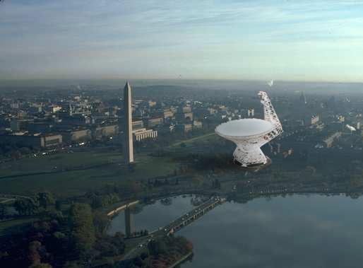
5 elescope Structure and Optics Large 100-m Diameter: High Sensitivity High Angular Resolution wavelength / Diameter
6
7
8

9 elescope Structure and Optics

10 GB elescope Optics 110 m x 100 m of a 208 m parent paraboloid Effective diameter: 100 m Off axis - Clear/Unblocked Aperture


11 High Dynamic Range High Fidelity Images elescope Optics

12 elescope Optics Stray Radiation Blockage Spillover

13 elescope Optics
14


15 elescope Optics Prime Focus: Retractable boom Gregorian Focus: 8-m subreflector - 6-degrees of freedom


16 elescope Optics Rotating urret with 8 receiver bays


17 elescope Structure Fully Steerable Elevation Limit: 5 Can observe 85% of the entire Celestial Sphere Slew Rates: Azimuth - 40 /min; Elevation - 20 /min

18 National Radio Quiet Zone

19
20


21 National Radio Quiet Zone
22
23 Index of Refraction Atmosphere Weather (i.e., time) and frequency dependent Real Part: Bends the light path Imaginary part: Opacity Winds Wind-induced pointing errors Safety
24 he Influence of the Atmosphere and Weather at cm- and mm-wavelengths Opacity Calibration System performance sys Observing techniques Hardware design Refraction Pointing Air Mass Calibration Interferometer & VLB phase errors Aperture phase errors Cloud Cover Continuum performance Calibration Winds Pointing Safety elescope Scheduling Proportion of proposals that should be accepted elescope productivity

25 Weather Forecasts for Radio Astronomy
26 Weather Forecasts for Radio Astronomy
27

28 elescope Structure

29 GB active surface system Surface has 2004 panels average panel rms: 68 µm 2209 precision actuators 29


30 Surface Panel Actuators One of 2209 actuators. Actuators are located under each set of surface panel corners 30 Actuator Control Room 26,508 control and supply wires terminated in this room

31 31 Finite Element Model Predictions

32 Mechanical adjustment of the panels 32

33 33 Image quality and efficiency

 6.")
34 Image quality, efficiency, resolution HPBW 1.2 D 40' at 300MHz(1m) 9' at 1420 M Hz(21cm) 6.5"at 115 GHz(3 mm) 34

35 Image quality and efficiency Aperture Efficiency A Detected Incident Power Power
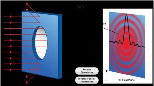
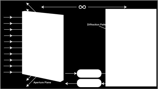
36 36 Holography
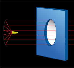
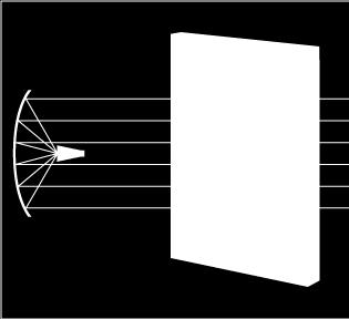
37 37 Holography
")
38 Surface accuracy (rms) = 240 µm
39 Aperture Efficiency A 0.7e (4 / ) 2 = rms surface error
40 elescope Structure Blind Pointing: (1 point/focus) 2 ( 5 arcsec focus ) 2.5 mm Offset Pointing: (90 min) 2 ( 2.7 arcsec focus ) 1.5 mm Continuous racking: (30 min) 2 1 arcsec
41 Receivers Receiver Operating Range Status Prime Focus GHz Commissioned Prime Focus GHz Commissioned L Band GHz Commissioned S Band GHz Commissioned C Band GHz Recently upgraded X Band GHz Commissioned Ku Band GHz Commissioned K Band Array GHz Commissioned Ka Band GHz Commissioned Q Band GHz Commissioned W Band GHz Commissioned Mustang Bolometer GHz Being upgraded ARGUS GHz Being commissioned

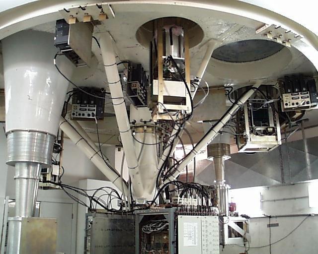
42 Receiver Room
43 ypical Receiver

44 Receiver Feeds

45 ypical Receiver
46 ypical Components Amplifiers Splitters Mixers Couplers Attenuators Power Detectors Filters Synthesizers Switches Multipliers


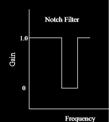
47 ypes of Filters Edges are smoother than illustrated
48 ypes of Mixers f f IF n and m are positive or negative integers, usually 1 or -1 f LO f IF = n*f LO + m*f Up Conversion : f IF > f Down Conversion : f IF < f Lower Side Band : f LO > f - Sense of frequency flips Upper Side Band : f LO < f
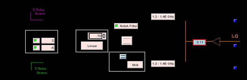
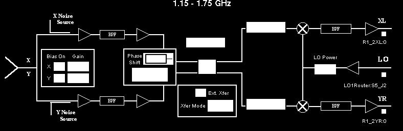
49 40-Ft System Determine values for the first LO for the 40-ft when Observing HI at 1420 MHz
50
51
52
53 GB Astrid program does all the hard work for you.. configline = """ receiver = "Rcvr1_2" beam = B1" obstype = "Spectroscopy" backend = "Spectrometer" nwin = 1 restfreq = deltafreq = 0 bandwidth = 12.5 swmode = "tp" swtype = "none" swper = 1.0 swfreq = 0.0, 0.0 tint = 30 vlow = 0 vhigh = 0 vframe = "lsrk" vdef = "Radio" noisecal = "lo" pol = "Linear" nchan = "low" spect.levels = 3 """

54 Power Balancing/Leveling and Non- Linearity
55 Spectral-line observations Raw Data Reduced Data High Quality Reduced Data Problematic
56 Reference observations Difference a signal observation with a reference observation ypes of reference observations Frequency Switching In or Out-of-band Position Switching Beam Switching Move Subreflector Receiver beam-switch Dual-Beam Nodding Move telescope Move Subreflector
57 Model Receiver
58 Out-Of-Band Frequency Switching
59 On-Off Observing Noise Diode Signal Signal Detector
60 Nodding with dual-beam receivers - elescope motion Optical aberrations Difference in spillover/ground pickup Removes any fast gain/bandpass changes Overhead from moving the telescope. All the time is spent on source
61 Nodding with dual-beam receivers - Subreflector motion Optical aberrations Difference in spillover/ground pickup Removes any fast gain/bandpass changes Low overhead. All the time is spent on source
 Aperture A (sq.m.")
62 Intrinsic Power P (Watts) Distance R (meters) Aperture A (sq.m.) Flux = Power Received/Area Flux Density (S) = Power Received/Area/bandwidth Bandwidth (BW) A Jansky is a unit of flux density Watts / m / Hz P S 2 4R BW 2k S A A A g e AirMass Gain Gain Gain A S 2.84 A A A g 2761 for GB 2.0 for GB at low frequencies
63 ) (1 ) (1 Airmass AM Airmass Background A CMB l Spill l Rcvr SYS e e 2 1 G G t BW SYS System emperature Radiometer Equation

64 40-Ft System
65 ) (1 ) (1 Airmass AM Airmass Background A CMB l Spill l Rcvr SYS e e System emperature ) (1 ) (1 Airmass AM Airmass Background A CMB l Spill l NoiseDiode Rcvr SYS e e
66
67 SYS s G Electronic V System emperature NoiseDiode CalOnOff Electronics NoiseDiode Electronics SYS Electronics CalOnOff V G G G V ) (1 ) (1 Airmass AM Airmass Background A CMB l Spill l Rcvr DiodeOff SYS e e ) (1 ) (1 Airmass AM Airmass Background A CMB l Spill l NoiseDiode Rcvr DiodeOn SYS e e
68 On-Off Observing Noise Diode Signal Signal Observe blank sky for 10 sec Move telescope to object & observe for 10 sec Move to blank sky & observe for 10 sec Fire noise diode & observe for 10 sec Observe blank sky for 10 sec Detector
69 Continuum - Point Sources On-Off Observing NoiseDiode =3K On Source Off Source Diode On Off Source
70 A Electronics SYS Electronics SigRef G G V Source Antenna emperature NoiseDiode CalOnOff Electronics NoiseDiode Electronics SYS Electronics CalOnOff V G G G V CalOnOff NoiseDiode RefCalOff SYS CalOnOff NoiseDiode SigRef A V V V V
71 A =6K NoiseDiode =3K Continuum - Point Sources On-Off Observing On Source Off Source Diode On Off Source SYS =20K
72 Converting A to Scientifically Useful Values A ( K) A Area e 2k Airmass S( W m 2 Hz 1 ) Point Source e Src MB e Airmass Src HPBW e Airmass 2 e B Airmass B Airmass ( K) Extended MB B source size ( K) Source ( K) Source source; HPBW HPBW depends upon but not point source ( K) Equivalent to a uniform source that fills just themain beam Src
Calibration. Ron Maddalena NRAO Green Bank November 2012
 Calibration Ron Maddalena NRAO Green Bank November 2012 Receiver calibration sources allow us to convert the backend s detected voltages to the intensity the signal had at the point in the system where
Guide to observation planning with GREAT
 Guide to observation planning with GREAT G. Sandell GREAT is a heterodyne receiver designed to observe spectral lines in the THz region with high spectral resolution and sensitivity. Heterodyne receivers
Antennas. Greg Taylor. University of New Mexico Spring Astronomy 423 at UNM Radio Astronomy
 Antennas Greg Taylor University of New Mexico Spring 2011 Astronomy 423 at UNM Radio Astronomy Radio Window 2 spans a wide range of λ and ν from λ ~ 0.33 mm to ~ 20 m! (ν = 1300 GHz to 15 MHz ) Outline
THEORY OF MEASUREMENTS
 THEORY OF MEASUREMENTS Brian Mason Fifth NAIC-NRAO School on Single-Dish Radio Astronomy Arecibo, PR July 2009 OUTLINE Antenna-Sky Coupling Noise the Radiometer Equation Minimum Tsys Performance measures
Antennas. Greg Taylor. University of New Mexico Spring Astronomy 423 at UNM Radio Astronomy
 Antennas Greg Taylor University of New Mexico Spring 2017 Astronomy 423 at UNM Radio Astronomy Outline 2 Fourier Transforms Interferometer block diagram Antenna fundamentals Types of antennas Antenna performance
Multiplying Interferometers
 Multiplying Interferometers L1 * L2 T + iv R1 * R2 T - iv L1 * R2 Q + iu R1 * L2 Q - iu Since each antenna can output both L and R polarization, all 4 Stokes parameters are simultaneously measured without
Observing Techniques and Calibration. David Frayer (Green Bank Observatory)
") Observing Techniques and Calibration David Frayer (Green Bank Observatory) The GBT provides a lot of observing choices Pick receiver based on frequency Pick backend based on observing type (line, continuum,
Observing Techniques and Calibration David Frayer (Green Bank Observatory) The GBT provides a lot of observing choices Pick receiver based on frequency Pick backend based on observing type (line, continuum,
Submillimeter (continued)
") Submillimeter (continued) Dual Polarization, Sideband Separating Receiver Dual Mixer Unit The 12-m Receiver Here is where the receiver lives, at the telescope focus Receiver Performance T N (noise temperature)
Submillimeter (continued) Dual Polarization, Sideband Separating Receiver Dual Mixer Unit The 12-m Receiver Here is where the receiver lives, at the telescope focus Receiver Performance T N (noise temperature)
Receiver Performance and Comparison of Incoherent (bolometer) and Coherent (receiver) detection
 and Coherent (receiver) detection") At ev gap /h the photons have sufficient energy to break the Cooper pairs and the SIS performance degrades. Receiver Performance and Comparison of Incoherent (bolometer) and Coherent (receiver) detection
At ev gap /h the photons have sufficient energy to break the Cooper pairs and the SIS performance degrades. Receiver Performance and Comparison of Incoherent (bolometer) and Coherent (receiver) detection
The 4mm (68-92 GHz) Receiver
 Receiver") Chapter 18 The 4mm (68-92 GHz) Receiver 18.1 Overview The 4 mm receiver ( W-band ) is a dual-beam, dual-polarization receiver which covers the frequency range of approximately 67-93 GHz. The performance
Chapter 18 The 4mm (68-92 GHz) Receiver 18.1 Overview The 4 mm receiver ( W-band ) is a dual-beam, dual-polarization receiver which covers the frequency range of approximately 67-93 GHz. The performance
G. Serra.
 G. Serra gserra@oa-cagliari.inaf.it on behalf of Metrology team* *T. Pisanu, S. Poppi, F.Buffa, P. Marongiu, R. Concu, G. Vargiu, P. Bolli, A. Saba, M.Pili, E.Urru Astronomical Observatory of Cagliari
To print higher-resolution math symbols, click the Hi-Res Fonts for Printing button on the jsmath control panel.
 To print higher-resolution math symbols, click the Hi-Res Fonts for Printing button on the jsmath control panel. Radiometers Natural radio emission from the cosmic microwave background, discrete astronomical
Antennas & Receivers in Radio Astronomy
 Antennas & Receivers in Radio Astronomy Mark McKinnon Fifteenth Synthesis Imaging Workshop 1-8 June 2016 Purpose & Outline Purpose: describe how antenna elements can affect the quality of images produced
EVLA Scientific Commissioning and Antenna Performance Test Check List
 EVLA Scientific Commissioning and Antenna Performance Test Check List C. J. Chandler, C. L. Carilli, R. Perley, October 17, 2005 The following requirements come from Chapter 2 of the EVLA Project Book.
Antennas and Receivers in Radio Astronomy
 Antennas and Receivers in Radio Astronomy Mark McKinnon Eleventh Synthesis Imaging Workshop Socorro, June 10-17, 2008 Outline 2 Context Types of antennas Antenna fundamentals Reflector antennas Mounts
Introduction to Radio Astronomy!
 Introduction to Radio Astronomy! Sources of radio emission! Radio telescopes - collecting the radiation! Processing the radio signal! Radio telescope characteristics! Observing radio sources Sources of
More Radio Astronomy
 More Radio Astronomy Radio Telescopes - Basic Design A radio telescope is composed of: - a radio reflector (the dish) - an antenna referred to as the feed on to which the radiation is focused - a radio
Sideband Smear: Sideband Separation with the ALMA 2SB and DSB Total Power Receivers
 and DSB Total Power Receivers SCI-00.00.00.00-001-A-PLA Version: A 2007-06-11 Prepared By: Organization Date Anthony J. Remijan NRAO A. Wootten T. Hunter J.M. Payne D.T. Emerson P.R. Jewell R.N. Martin
Introduction to Radio Astronomy
 Introduction to Radio Astronomy The Visible Sky, Sagittarius Region 2 The Radio Sky 3 4 Optical and Radio can be done from the ground! 5 Outline The Discovery of Radio Waves Maxwell, Hertz and Marconi
A new K-band (18-26 GHz) 7-horn multi-feed receiver: Calibration campaign at Medicina 32 m dish
 7-horn multi-feed receiver: Calibration campaign at Medicina 32 m dish") A new K-band (18-26 GHz) 7-horn multi-feed receiver: Calibration campaign at Medicina 32 m dish R.Verma, G.Maccaferri, A.Orfei I.Prandoni, L.Gregorini IRA 430/09 Contents 1 6 1.1 Goals............................................
A new K-band (18-26 GHz) 7-horn multi-feed receiver: Calibration campaign at Medicina 32 m dish R.Verma, G.Maccaferri, A.Orfei I.Prandoni, L.Gregorini IRA 430/09 Contents 1 6 1.1 Goals............................................
Antennas & Receivers in Radio Astronomy Mark McKinnon. Twelfth Synthesis Imaging Workshop 2010 June 8-15
 Antennas & Receivers in Radio Astronomy Mark McKinnon 2010 June 8-15 Outline Context Types of antennas Antenna fundamentals Reflector antennas Mounts Optics Antenna performance Aperture efficiency Pointing
NATIONAL RADIO ASTRONOMY OBSERVATORY Green Bank, West Virginia Electronics Division Internal Report No 76
 NATIONAL RADIO ASTRONOMY OBSERVATORY Green Bank, West Virginia Electronics Division Internal Report No 76 A NOVEL WAY OF BEAM-SWITCHING, PARTICULARLY SUITABLE AT MM WAVELENGTHS N. Albaugh and K. H. Wesseling
Very Long Baseline Interferometry
 Very Long Baseline Interferometry Cormac Reynolds, JIVE European Radio Interferometry School, Bonn 12 Sept. 2007 VLBI Arrays EVN (Europe, China, South Africa, Arecibo) VLBA (USA) EVN + VLBA coordinate
Single Dish Observing Techniques and Calibration
 Single Dish Observing Techniques and Calibration David Frayer (NRAO) {some slides taken from past presentations of Ron Maddalena and Karen O Neil} What does the telescope measure: Ta = antenna temperature
A Crash Course in Radio Astronomy and Interferometry: 1. Basic Radio/mm Astronomy
 A Crash Course in Radio Astronomy and Interferometry: 1. Basic Radio/mm Astronomy James Di Francesco National Research Council of Canada North American ALMA Regional Center Victoria (thanks to S. Dougherty,
OPTICS OF SINGLE BEAM, DUAL BEAM & ARRAY RECEIVERS ON LARGE TELESCOPES J A M E S W L A M B, C A L T E C H
 OPTICS OF SINGLE BEAM, DUAL BEAM & ARRAY RECEIVERS ON LARGE TELESCOPES J A M E S W L A M B, C A L T E C H OUTLINE Antenna optics Aberrations Diffraction Single feeds Types of feed Bandwidth Imaging feeds
IF/LO Systems for Single Dish Radio Astronomy Centimeter Wave Receivers
 IF/LO Systems for Single Dish Radio Astronomy Centimeter Wave Receivers Lisa Wray NAIC, Arecibo Observatory Abstract. Radio astronomy receivers designed to detect electromagnetic waves from faint celestial
Signal Flow & Radiometer Equation. Aletha de Witt AVN-Newton Fund/DARA 2018 Observational & Technical Training HartRAO
 Signal Flow & Radiometer Equation Aletha de Witt AVN-Newton Fund/DARA 2018 Observational & Technical Training HartRAO Understanding Radio Waves The meaning of radio waves How radio waves are created -
Introduction to DSTV Dish Observations. Alet de Witt AVN Technical Training 2016
 Introduction to DSTV Dish Observations Alet de Witt AVN Technical Training 2016 Outline Theory: - Radio Waves - Radio Telescope Antennas - Angular Sizes - Brightness Temperature and Antenna Temperature
Chapter 3. Instrumentation. 3.1 Telescope Site Layout. 3.2 Telescope Optics
 Chapter 3 Instrumentation 3.1 Telescope Site Layout The 12m is located on the southwest ridge of Kitt Peak, about two miles below the top of the mountain. Other telescopes on the southwest ridge are the
Observing Modes and Real Time Processing
 2010-11-30 Observing with ALMA 1, Observing Modes and Real Time Processing R. Lucas November 30, 2010 Outline 2010-11-30 Observing with ALMA 2, Observing Modes Interferometry Modes Interferometry Calibrations
The Cosmic Microwave Background Radiation B. Winstein, U of Chicago
 The Cosmic Microwave Background Radiation B. Winstein, U of Chicago Lecture #1 Lecture #2 What is it? How its anisotropies are generated? What Physics does it reveal? How it is measured. Lecture #3 Main
Spectral Line Calibration Techniques with Single Dish Telescopes. K. O Neil NRAO - GB
 Spectral Line Calibration Techniques with Single Dish Telescopes K. O Neil NRAO - GB Determining the Source Temperature Determining T source T A,meas (,az,za) = T src (,az,za) + T system Determining T
Recent progress and future development of Nobeyama 45-m Telescope
 Recent progress and future development of Nobeyama 45-m Telescope Masao Saito: Director of Nobeyama Radio Observatory Tetsuhiro Minamidani: Nobeyama Radio Observatory Outline Nobeyama 45-m Telescope Recent
Holography Transmitter Design Bill Shillue 2000-Oct-03
 Holography Transmitter Design Bill Shillue 2000-Oct-03 Planned Photonic Reference Distribution for Test Interferometer The transmitter for the holography receiver is made up mostly of parts that are already
Symmetry in the Ka-band Correlation Receiver s Input Circuit and Spectral Baseline Structure NRAO GBT Memo 248 June 7, 2007
 Symmetry in the Ka-band Correlation Receiver s Input Circuit and Spectral Baseline Structure NRAO GBT Memo 248 June 7, 2007 A. Harris a,b, S. Zonak a, G. Watts c a University of Maryland; b Visiting Scientist,
Recent Astronomical Commissioning Results for the Ka-band ( GHz) Receiver
 Receiver") May 1, 2007 Recent Astronomical Commissioning Results for the Ka-band (26.0-40 GHz Receiver D.J. Pisano, Ron Maddalena, Charles Figura, Jeff Wagg ABSTRACT We present an observing procedure and calibration
May 1, 2007 Recent Astronomical Commissioning Results for the Ka-band (26.0-40 GHz Receiver D.J. Pisano, Ron Maddalena, Charles Figura, Jeff Wagg ABSTRACT We present an observing procedure and calibration
L- and S-Band Antenna Calibration Using Cass. A or Cyg. A
 L- and S-Band Antenna Calibration Using Cass. A or Cyg. A Item Type text; Proceedings Authors Taylor, Ralph E. Publisher International Foundation for Telemetering Journal International Telemetering Conference
Planning (VLA) observations
 observations") Planning () observations 14 th Synthesis Imaging Workshop (May 2014) Loránt Sjouwerman National Radio Astronomy Observatory (Socorro, NM) Atacama Large Millimeter/submillimeter Array Karl G. Jansky Very
Planning () observations 14 th Synthesis Imaging Workshop (May 2014) Loránt Sjouwerman National Radio Astronomy Observatory (Socorro, NM) Atacama Large Millimeter/submillimeter Array Karl G. Jansky Very
A Quick Review. Spectral Line Calibration Techniques with Single Dish Telescopes. The Rayleigh-Jeans Approximation. Antenna Temperature
 Spectral Line Calibration Techniques with Single Dish Telescopes A Quick Review K. O Neil NRAO - GB A Quick Review A Quick Review The Rayleigh-Jeans Approximation Antenna Temperature Planck Law for Blackbody
School of Electrical Engineering. EI2400 Applied Antenna Theory Lecture 8: Reflector antennas
 School of Electrical Engineering EI2400 Applied Antenna Theory Lecture 8: Reflector antennas Reflector antennas Reflectors are widely used in communications, radar and radio astronomy. The largest reflector
Fundamentals of Radio Astronomy. Lyle Hoffman, Lafayette College ALFALFA Undergraduate Workshop Arecibo Observatory, 2008 Jan. 13
 Fundamentals of Radio Astronomy Lyle Hoffman, Lafayette College ALFALFA Undergraduate Workshop Arecibo Observatory, 2008 Jan. 13 Outline Sources in brief Radiotelescope components Radiotelescope characteristics
Why Single Dish? Darrel Emerson NRAO Tucson. NAIC-NRAO School on Single-Dish Radio Astronomy. Green Bank, August 2003.
 Why Single Dish? Darrel Emerson NRAO Tucson NAIC-NRAO School on Single-Dish Radio Astronomy. Green Bank, August 2003. Why Single Dish? What's the Alternative? Comparisons between Single-Dish, Phased Array
EVLA Memo 105. Phase coherence of the EVLA radio telescope
 EVLA Memo 105 Phase coherence of the EVLA radio telescope Steven Durand, James Jackson, and Keith Morris National Radio Astronomy Observatory, 1003 Lopezville Road, Socorro, NM, USA 87801 ABSTRACT The
ANTENNA INTRODUCTION / BASICS
 ANTENNA INTRODUCTION / BASICS RULES OF THUMB: 1. The Gain of an antenna with losses is given by: 2. Gain of rectangular X-Band Aperture G = 1.4 LW L = length of aperture in cm Where: W = width of aperture
ALMA water vapour radiometer project
 ALMA water vapour radiometer project Why water vapour radiometers? Science requirements/instrument specifications Previous work ALMA Phase 1 work Kate Isaak and Richard Hills Cavendish Astrophysics, Cambridge
ATCA Antenna Beam Patterns and Aperture Illumination
 1 AT 39.3/116 ATCA Antenna Beam Patterns and Aperture Illumination Jared Cole and Ravi Subrahmanyan July 2002 Detailed here is a method and results from measurements of the beam characteristics of the
Why Single Dish? Darrel Emerson NRAO Tucson. NAIC-NRAO School on Single-Dish Radio Astronomy. Green Bank, August 2003.
 Why Single Dish? Darrel Emerson NRAO Tucson NAIC-NRAO School on Single-Dish Radio Astronomy. Green Bank, August 2003. Why Single Dish? What's the Alternative? Comparisons between Single-Dish, Phased Array
Millimetre and Radio Astronomy Techniques for Star Forma:on Studies II
 Millimetre and Radio Astronomy Techniques for Star Forma:on Studies II John Conway Onsala Space Observatory, Sweden &Nordic ALMA ARC node (john.conway@chalmers.se) Today prac:cal details... For details
Introduction to Radio Astronomy. Richard Porcas Max-Planck-Institut fuer Radioastronomie, Bonn
 Introduction to Radio Astronomy Richard Porcas Max-Planck-Institut fuer Radioastronomie, Bonn 1 Contents Radio Waves Radio Emission Processes Radio Noise Radio source names and catalogues Radio telescopes
d (Eqn 2), Source temperature distribution, Normalized antenna pattern 4 A Antenna gain as a power ratio
, Source temperature distribution, Normalized antenna pattern 4 A Antenna gain as a power ratio") Quiet un 0 MHz ntenna emperature nalysis Dave ypinski, March 013 olar radio bursts are easy to observe with practically any receiver. he question arises: can we see the quiet un with a Radio Jove radio
Quiet un 0 MHz ntenna emperature nalysis Dave ypinski, March 013 olar radio bursts are easy to observe with practically any receiver. he question arises: can we see the quiet un with a Radio Jove radio
Extra slides. 10/05/2011 SAC meeting IRAM Grenoble 1
 Extra slides 10/05/2011 SAC meeting IRAM Grenoble 1 New NIKA spectral responses Bands spectral response obtained with a Martin-Puplett interferometer 10/05/2011 SAC meeting IRAM Grenoble 2 New NIKA backend
Very Long Baseline Interferometry
 Very Long Baseline Interferometry Shep Doeleman (Haystack) Ylva Pihlström (UNM) Craig Walker (NRAO) Eleventh Synthesis Imaging Workshop Socorro, June 10-17, 2008 What is VLBI? 2 VLBI is interferometry
EVLA Memo #119 Wide-Band Sensitivity and Frequency Coverage of the EVLA and VLA L-Band Receivers
 EVLA Memo #119 Wide-Band Sensitivity and Frequency Coverage of the EVLA and VLA L-Band Receivers Rick Perley and Bob Hayward January 17, 8 Abstract We determine the sensitivities of the EVLA and VLA antennas
Commonly Used GO Keywords
 Robert C. Byrd Green Bank Telescope NRAO Green Bank Toney Minter and Dana Balser 17th September 2003 GBT SOFTWARE PROJECT NOTE 21.2 Commonly Used GO Keywords HTML version Available 1 Contents 1 Introduction
J/K). Nikolova
. Nikolova") Lecture 7: ntenna Noise Temperature and System Signal-to-Noise Ratio (Noise temperature. ntenna noise temperature. System noise temperature. Minimum detectable temperature. System signal-to-noise ratio.)
Lecture 7: ntenna Noise Temperature and System Signal-to-Noise Ratio (Noise temperature. ntenna noise temperature. System noise temperature. Minimum detectable temperature. System signal-to-noise ratio.)
VLBI2010 Current status of the TWIN radio telescope project at Wettzell, Germany
 VLBI2010 Current status of the TWIN radio telescope project at Wettzell, Germany Alexander Neidhardt, FESG/TU München (on behalf of the BKG) G. Kronschnabl, (BKG); Hase, H. (BKG); Schreiber, U. (BKG);
GBT Spectral Baseline Investigation Rick Fisher, Roger Norrod, Dana Balser (G. Watts, M. Stennes)
") GBT Spectral Baseline Investigation Rick Fisher, Roger Norrod, Dana Balser (G. Watts, M. Stennes) Points to Note: Wider bandwidths than were used on 140 Foot Cleaner antenna so other effects show up Larger
GBT Spectral Baseline Investigation Rick Fisher, Roger Norrod, Dana Balser (G. Watts, M. Stennes) Points to Note: Wider bandwidths than were used on 140 Foot Cleaner antenna so other effects show up Larger
Microwave-Radiometer
 Microwave-Radiometer Figure 1: History of cosmic background radiation measurements. Left: microwave instruments, right: background radiation as seen by the corresponding instrument. Picture: NASA/WMAP
EVLA Memo 137 Performance Tests of the EVLA K, Ka, and Q-Band Receivers
 EVLA Memo 137 Performance Tests of the EVLA K, Ka, and Q-Band Receivers Rick Perley, Bob Hayward and Bryan Butler NRAO August 4, 2009 Abstract Efficiency observations performed in January and February
The DARPA 100Gb/s RF Backbone Program
 The DARPA 100Gb/s RF Backbone Program Dr. Ted Woodward Program Manager, DARPA/STO Briefing Prepared for NSF mmw RCN workshop Madison, WI 19 July 2017 1 100 Gb/s RF Backbone (100G) Objective: Capacity AND
LOFAR: Special Issues
 Netherlands Institute for Radio Astronomy LOFAR: Special Issues John McKean (ASTRON) ASTRON is part of the Netherlands Organisation for Scientific Research (NWO) 1 Preamble http://www.astron.nl/~mckean/eris-2011-2.pdf
The WVR at Effelsberg. Thomas Krichbaum
 The WVR at Effelsberg Alan Roy Ute Teuber Helge Rottmann Thomas Krichbaum Reinhard Keller Dave Graham Walter Alef The Scanning 18-26 GHz WVR for Effelsberg ν = 18.5 GHz to 26.0 GHz Δν = 900 MHz Channels
Radar Reprinted from "Waves in Motion", McGourty and Rideout, RET 2005
 Radar Reprinted from "Waves in Motion", McGourty and Rideout, RET 2005 What is Radar? RADAR (Radio Detection And Ranging) is a way to detect and study far off targets by transmitting a radio pulse in the
Analysis and Compensation of Subreflector Displacement for the Parabolic Antenna of a Radio Telescope
 Progress In Electromagnetics Research M, Vol. 44, 59 68, 215 Analysis and Compensation of Subreflector Displacement for the Parabolic Antenna of a Radio Telescope Lan Chen 1, Zheng Xiong Sun 1, Jin Qing
Technical Considerations: Nuts and Bolts Project Planning and Technical Justification
 Technical Considerations: Nuts and Bolts Project Planning and Technical Justification Atacama Large Millimeter/submillimeter Array Expanded Very Large Array Robert C. Byrd Green Bank Telescope Very Long
Phased Array Feeds & Primary Beams
 Phased Array Feeds & Primary Beams Aidan Hotan ASKAP Deputy Project Scientist 3 rd October 2014 CSIRO ASTRONOMY AND SPACE SCIENCE Outline Review of parabolic (dish) antennas. Focal plane response to a
Sub-millimeter Wave Planar Near-field Antenna Testing
 Sub-millimeter Wave Planar Near-field Antenna Testing Daniёl Janse van Rensburg 1, Greg Hindman 2 # Nearfield Systems Inc, 1973 Magellan Drive, Torrance, CA, 952-114, USA 1 drensburg@nearfield.com 2 ghindman@nearfield.com
Smart Antennas in Radio Astronomy
 Smart Antennas in Radio Astronomy Wim van Cappellen cappellen@astron.nl Netherlands Institute for Radio Astronomy Our mission is to make radio-astronomical discoveries happen ASTRON is an institute for
ALMA Memo #289 Atmospheric Noise in Single Dish Observations Melvyn Wright Radio Astronomy Laboratory, University of California, Berkeley 29 February
 ALMA Memo #289 Atmospheric Noise in Single Dish Observations Melvyn Wright Radio Astronomy Laboratory, University of California, Berkeley 29 February 2000 Abstract Atmospheric noise and pointing fluctuations
Final Feed Selection Study For the Multi Beam Array System
 National Astronomy and Ionosphere Center Arecibo Observatory Focal Array Memo Series Final Feed Selection Study For the Multi Beam Array System By: Germán Cortés-Medellín CORNELL July/19/2002 U n i v e
Comparing MMA and VLA Capabilities in the GHz Band. Socorro, NM Abstract
 Comparing MMA and VLA Capabilities in the 36-50 GHz Band M.A. Holdaway National Radio Astronomy Observatory Socorro, NM 87801 September 29, 1995 Abstract I explore the capabilities of the MMA and the VLA,
Phased Array Feeds A new technology for multi-beam radio astronomy
 Phased Array Feeds A new technology for multi-beam radio astronomy Aidan Hotan ASKAP Deputy Project Scientist 2 nd October 2015 CSIRO ASTRONOMY AND SPACE SCIENCE Outline Review of radio astronomy concepts.
ANTENNA INTRODUCTION / BASICS
 Rules of Thumb: 1. The Gain of an antenna with losses is given by: G 0A 8 Where 0 ' Efficiency A ' Physical aperture area 8 ' wavelength ANTENNA INTRODUCTION / BASICS another is:. Gain of rectangular X-Band
Chapter 4 The RF Link
 Chapter 4 The RF Link The fundamental elements of the communications satellite Radio Frequency (RF) or free space link are introduced. Basic transmission parameters, such as Antenna gain, Beamwidth, Free-space
Phased Array Feeds A new technology for wide-field radio astronomy
 Phased Array Feeds A new technology for wide-field radio astronomy Aidan Hotan ASKAP Project Scientist 29 th September 2017 CSIRO ASTRONOMY AND SPACE SCIENCE Outline Review of radio astronomy concepts
Introduction to Interferometry. Michelson Interferometer. Fourier Transforms. Optics: holes in a mask. Two ways of understanding interferometry
 Introduction to Interferometry P.J.Diamond MERLIN/VLBI National Facility Jodrell Bank Observatory University of Manchester ERIS: 5 Sept 005 Aim to lay the groundwork for following talks Discuss: General
Spectral Line Calibration Techniques with Single Dish Telescopes. K. O Neil NRAO - GB
 Spectral Line Calibration Techniques with Single Dish Telescopes K. O Neil NRAO - GB A Quick Review Review: The Rayleigh-Jeans Approximation Planck Law for Blackbody radiation: B= 2hν 3 1 If ν~ghz, often
Why Single Dish? Why Single Dish? Darrel Emerson NRAO Tucson
 Why Single Dish? Darrel Emerson NRAO Tucson Why Single Dish? What's the Alternative? Comparisons between Single-Dish, Phased Array & Interferometers Advantages and Disadvantages of Correlation Interferometer
Memo 65 SKA Signal processing costs
 Memo 65 SKA Signal processing costs John Bunton, CSIRO ICT Centre 12/08/05 www.skatelescope.org/pages/page_memos.htm Introduction The delay in the building of the SKA has a significant impact on the signal
Aperture Antennas. Reflectors, horns. High Gain Nearly real input impedance. Huygens Principle
 Antennas 97 Aperture Antennas Reflectors, horns. High Gain Nearly real input impedance Huygens Principle Each point of a wave front is a secondary source of spherical waves. 97 Antennas 98 Equivalence
Chapter 5. SPECTRAL LINE OBSERVING 1
 Chapter 5. SPECTRAL LINE OBSERVING 1 CHAPTER 5 Spectral Line Observing 5.1 Startup Checklist Once the scientific goals of the observing session are clearly in mind, you must decide upon the equipment and
What does reciprocity mean
 Antennas Definition of antenna: A device for converting electromagnetic radiation in space into electrical currents in conductors or vice-versa. Radio telescopes are antennas Reciprocity says we can treat
EVLA Antenna and Array Performance. Rick Perley
 EVLA Antenna and Array Performance System Requirements EVLA Project Book, Chapter 2, contains the EVLA system requirements. For most, astronomical tests are necessary to determine if the array meets requirements.
AVN Training HartRAO 2016
 AVN Training HartRAO 2016 Microwave 1 Overview Introduction to basic components used in microwave receivers. Performance characteristics of these components. Assembly of components into a complete microwave
arxiv:astro-ph/ v1 21 Jun 2006
 Ð Ú Ø ÓÒ Ò Ð Ô Ò Ò Ó Ø ËÅ ÒØ ÒÒ ÓÙ ÔÓ Ø ÓÒ Satoki Matsushita a,c, Masao Saito b,c, Kazushi Sakamoto b,c, Todd R. Hunter c, Nimesh A. Patel c, Tirupati K. Sridharan c, and Robert W. Wilson c a Academia
Wide-Band Imaging. Outline : CASS Radio Astronomy School Sept 2012 Narrabri, NSW, Australia. - What is wideband imaging?
 Wide-Band Imaging 24-28 Sept 2012 Narrabri, NSW, Australia Outline : - What is wideband imaging? - Two Algorithms Urvashi Rau - Many Examples National Radio Astronomy Observatory Socorro, NM, USA 1/32
THE KAROO ARRAY TELESCOPE (KAT) & FPA EFFORT IN SOUTH AFRICA
 & FPA EFFORT IN SOUTH AFRICA") THE KAROO ARRAY TELESCOPE (KAT) & FPA EFFORT IN SOUTH AFRICA Dr. Dirk Baker (KAT FPA Sub-system Manager) Prof. Justin Jonas (SKA SA Project Scientist) Ms. Anita Loots (KAT Project Manager) Mr. David de
THE KAROO ARRAY TELESCOPE (KAT) & FPA EFFORT IN SOUTH AFRICA Dr. Dirk Baker (KAT FPA Sub-system Manager) Prof. Justin Jonas (SKA SA Project Scientist) Ms. Anita Loots (KAT Project Manager) Mr. David de
IF/LO Systems for Single Dish Radio Astronomy cm-wave Receivers
 IF/LO Systems for Single Dish Radio Astronomy cm-wave Receivers Lisa Wray, Arecibo Observatory NRAO/NAIC Single Dish Summer School August 2003 Introduction to Receivers a specialized class of microwave
Specifications for the GBT spectrometer
 GBT memo No. 292 Specifications for the GBT spectrometer Authors: D. Anish Roshi 1, Green Bank Scientific Staff, J. Richard Fisher 2, John Ford 1 Affiliation: 1 NRAO, Green Bank, WV 24944. 2 NRAO, Charlottesville,
Coherent Receivers Principles Downconversion
 Coherent Receivers Principles Downconversion Heterodyne receivers mix signals of different frequency; if two such signals are added together, they beat against each other. The resulting signal contains
Sardinia Radio Telescope
 Sardinia Radio Telescope Current status and future developments Carlo Migoni @ INAF - OAC Funded by: Italian Ministry of Education and Scientific Research (MIUR) Sardinia Regional Government (RAS) Italian
Giant Metrewave Radio Telescope (GMRT) - Introduction, Current System & ugmrt
 - Introduction, Current System & ugmrt") Giant Metrewave Radio Telescope (GMRT) - Introduction, Current System & ugmrt Kaushal D. Buch Digital Backend Group, Giant Metrewave Radio Telescope kdbuch@gmrt.ncra.tifr.res.in Low frequency dipole array
Giant Metrewave Radio Telescope (GMRT) - Introduction, Current System & ugmrt Kaushal D. Buch Digital Backend Group, Giant Metrewave Radio Telescope kdbuch@gmrt.ncra.tifr.res.in Low frequency dipole array
Astronomische Waarneemtechnieken (Astronomical Observing Techniques)
") Astronomische Waarneemtechnieken (Astronomical Observing Techniques) 7 th Lecture: 15 October 01 1. Introduction. Radio Emission 3. Observing 4. Antenna Technology 5. Receiver Technolgy 6. Back Ends 7.
Astronomische Waarneemtechnieken (Astronomical Observing Techniques) 7 th Lecture: 15 October 01 1. Introduction. Radio Emission 3. Observing 4. Antenna Technology 5. Receiver Technolgy 6. Back Ends 7.
The VK3UM Radiation and System Performance Calculator
 The VK3UM Radiation and System Performance Calculator 1. Disclaimer... 2 2. Background... 2 3. Calculations... 2 4. Features... 2 5. Default Parameters... 3 6. Parameter Description... 4 7. On Axis Exclusion
DESIGN AND CONSTRUCTION OF THE COSMIC MICROWAVE RADIOMETER
 DESIGN AND CONSTRUCTION OF THE COSMIC MICROWAVE RADIOMETER Jack Gelfand PhD Portland, ME USA Jack.gelfand@oswego.edu HOW CAN I DETECT THE COSMIC MICROWAVE BACKGROUND? Difficult to find the important design
Introduction to interferometry with bolometers: Bob Watson and Lucio Piccirillo
 Introduction to interferometry with bolometers: Bob Watson and Lucio Piccirillo Paris, 19 June 2008 Interferometry (heterodyne) In general we have i=1,...,n single dishes (with a single or dual receiver)
Progress Towards Coherent Multibeam Arrays
 Progress Towards Coherent Multibeam Arrays Doug Henke NRC Herzberg Astronomy and Astrophysics, Victoria, Canada August 2016 ALMA Band 3 Receiver (84 116 GHz) Dual linear, 2SB Feed horn OMT (two linear
Satellite Signals and Communications Principles. Dr. Ugur GUVEN Aerospace Engineer (P.hD)
") Satellite Signals and Communications Principles Dr. Ugur GUVEN Aerospace Engineer (P.hD) Principle of Satellite Signals In essence, satellite signals are electromagnetic waves that travel from the satellite
Satellite Signals and Communications Principles Dr. Ugur GUVEN Aerospace Engineer (P.hD) Principle of Satellite Signals In essence, satellite signals are electromagnetic waves that travel from the satellite
Deep- Space Optical Communication Link Requirements
 Deep- Space Optical Communication Link Requirements Professor Chester S. Gardner Department of Electrical and Computer Engineering University of Illinois cgardner@illinois.edu Link Equation: For a free-