Antenna Fundamentals Basics antenna theory and concepts
|
|
|
- Ashlie Potter
- 6 years ago
- Views:
Transcription

1 Antenna Fundamentals Basics antenna theory and concepts M. Haridim Brno University of Technology, Brno February
2 Topics What is antenna Antenna types Antenna parameters: radiation pattern, directivity, efficiency, gain, radiation resistance, bandwidth, beamwidth Antenna array Dipole Monopole Loop antennas 2
3 What is antenna? A passive device acting as transition between some form of transmission line and the space. Signals from an RF transmitter are delivered via a transmission line to the antenna, which launches them as electromagnetic waves in the space, or vice versa. The shape and size of the current carrying structure determine how much energy is radiated, direction of propagation and how well the radiation is captured. Reciprocity property: The same antenna can be used in both transmitting and receiving modes. 3
4 Antenna types Antennas can be of either wire or aperture types. Wire type: dipole, monopole, loop, helix, Yagi-Uda. Aperture type: horn, reflector. 4
5 Common types of antennas: -1 (p. 389) ingle-element antennas. 5
6 Radiation intensity I(, ) [W/str] is the average power radiated per unit solid angle in direction (, ). Integration of I over the whole space (4 Str) gives the total radiated power. Power density [w/m 2 ] is the time-average of the Poynting vector 6
7 Near/far field regions Radiating Far- Field Region ( Fraunhofer Zone) Radiating Near- Field Region (Fresnel Zone) Reactive Near- Field Region ( Rayleigh Zone) infinity 7
8 Near/far field regions The boundary of near/far field zones is commonly accepted as r 2 2D D is the largest dimension on the antenna element, and assumed D>λ.
9 Wire Antenna Near/Far Field Spatial Distribution To feature the spatial dependence of the field intensity, we substitute all antenna and media parameters with constants H ja 1 a 1 r r E b jb b jb r r r r r 1 1 E jc1 c2 jc 2 3 r 3 r r Radiating Antenna + I ant E rad H rad F I E L D Z O N E S I II III Near-Field Reactive Near-Field Radiating Far-Field radiating 9
10 Near/Far Field of Aperture Antennas The fictional HARD field limits between the near and far field zones 10
11 Radiation pattern 2D vs. 3D E-plane (E and boresight direction) and H-plane Main, side and back lobes Isotropic Radiation Pattern, constant in both azimuth and elevation planes. Omni Directional Radiation Pattern. Directional Radiation Pattern- contains one main beam (lobe) in both azimuth and elevation planes. ( a ) 11


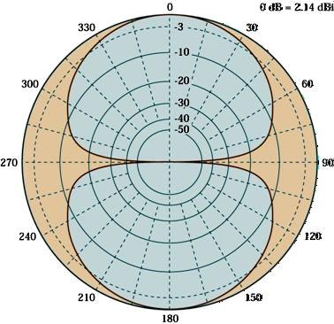
12 Radiation patters shown in polar plots
13 Directivity D(, ) An antenna s directivity is determined by the directionality of its radiation pattern. It is defined as the ratio between its radiation intensity and that of an isotropic antenna, radiating the same total power. Proportional to the radiation intensity. Max. directivity D max is the Max. value of D(, ). Not related to matching level 13
14 Efficiency The average power delivered to the antenna s input is P inc = P rad + P loss Antenna s efficiency is defined as Prad P rad P P P inc rad loss Loss mechanisms: dielectric losses, conduction losses, and reflection (mismatch) losses 14

15 Gain G(, ) Antenna s directivity has no information about the antenna s efficiency. The gain of an antenna is a function of both directivity and efficiency. The max gain occurs when the directivity is max. It s expressed in dbi, with respect to an isotropic antenna, or in dbd. 15
16 Antenna's Input Impedance and Radiation Resistance a Ra jxa Ra Rrad Rloss The real part of the antenna impedance consists of radiation resistance R rad and a dissipative resistance R loss (ohmic and dielectric losses). R rad at represents the useful part of the input power. In order to avoid reflection of the incident power, the antenna input impedance must be equal to the line's characteristic impedance, for the whole operation bandwidth. The mismatch is measured by the Voltage Standing Wave Ratio- VSWR. 16
17 Example A /2 dipole with a total input impedance of 75 +j40 and loss resistance 2 is fed by a power amplifier whose output voltage and impedance are 5cos 0 t and 50+j30, respectively. Find the power delivered to antenna, the radiated power and the amount of power dissipated by the antenna (ohmic losses). Find the power delivered to antenna, the radiated power and the amount of power dissipated by the antenna (ohmic losses). 17
18 Solution First, we find the current (phasor) in the equivalent circuit I V 5 Z Z R 50 j30 75 j40 s ant loss o I ma The power delivered from the power amplifier is 1 * 1 p Re{ v in s I } Re{.. }. mw 2 2 The radiated power rad prad I R (. ). mw 2 2 And the dissipated power 2 1 P 1 diss I R loss.. mw 2 18
19 The Effective Area of a Receiving Antenna The antenna's gain applies to both transmitting and receiving modes. However, it is more convenient to characterize a receiving antenna by its effective area that is given by the ratio between the power flux incident on the antenna and the power delivered to a matched load. It can be shown that the following relationship between antenna's gain and effective area prevails: G 4 Ae 2 19
20 Beam-width The are some zeros and nulls in radiation pattern, indicating no radiations. A directional antenna directs radiation in one or more directions. The width of this beam is defined as the angle between its half-power points. A half-wave dipole has beam-widths of about 78º and 360º in horizontal and vertical directions. The directivity of an antenna increases as its beamwidth is made smaller, as the energy radiated is concentrated into a smaller solid angle 20
21 Polarization The polarization of EM waves is determined by the direction of the electric field, and that of an antenna is defined as the polarization of its far field.. A dipole antenna, for example, produces a linearly polarized wave aligned with its axis. It picks-up maximum power energy in co-pol (co-polarization) operation, i.e. when its axis is aligned to the polarization of the impinging waves. In the cross-pol operation, on the other hand, it receives no radiation, as its axis is orthogonal to the polarization of the incident waves. The cross-pol level (in db) of an antenna denotes the ratio between the maximum received power in the co-pol and cross-pol operations. 21
22 Antenna arrays Antenna arrays are formed by an assembly of identical (in most cases) radiating elements, arranged in either a one-dimensional (1D) or twodimensional (2D) structure. The design of a single antenna, such as a resonance wire antenna, allows for limited control of its properties, especially its gain and radiation pattern. Greater design flexibility as well as improved performance can be achieved by arranging multiple spatially separated antennas that are separately driven, at the cost of increased size and complexity. Antenna arrays are used for increasing the antenna gain, combatting interference from certain directions, steering the boresight direction, and direction finding. 22
23 Dipole Dipole is the simplest antenna consisting of two straight pieces of wire or metal rods, fed at the center. The length of the dipole arms determines its characteristics, e.g. impedance, operating frequency, etc. 23
24 The dipole antenna radiates energy in all directions perpendicular to its axis, and no radiation along its axis. Thus, dipole has some directionality. In the case of a Hertzian dipole it is given by D(, ) 15. sin 2 So the maximum directivity is D 15. max 24
25 For a half-wave dipole the directivity is slightly higher, that is D max =1.64, its HPBW is 78 degree and its radiation resistance is R rad
26 . Elementary dipole An elementary dipole or Hertzian dipole, is a wire segment whose length L is very small compared to wavelength Assuming a vertical Hertzian dipole placed at the origin and excited by a sinusoidal current I I0 sint jr I0Le 0 r E Hr H 0 E j sin 4 r Where E 0 H In free space is the intrinsic impedance of the medium
27 L I0 2 P av 05. sin ( 4 r ) L I0 2 I(, ) sin
28 Current distribution If the wire diameter d << λ, the wave pattern along the dipole arms is sinusoidal with a null at the end. For center-fed dipoles: L << L = /2 No phase reversal No phase reversal 28
29 No phase reversal Phase reversal /2 < L < < L < 3/2 29
30 Monopole Monopole are unbalanced antenna, and hence they can be fed with an unbalanced feed lines such as coaxial cables. Like dipoles, monopoles are omnidirectional, but in contrast to dipoles that are balanced antenna, monopoles are, 30
31 Whip Whip antenna is the most common example of a monopole radio antenna, almost always vertically mounted onto a base vehicle, resulting in vertical polarization. Whip antennas are easy to install and operate, but suffer low efficiency when they lack a stable ground. The length of the whip determines its operating wavelength. It is possible to shorten the whip by inserting a coil anywhere along the antenna. 31
32 Loop antenna Loop is a very versatile antenna. It has different forms: circle, rectangle, square, triangle, ellipse, etc. A small loops is equivalent to an infinitesimal dipole, whose axis is perpendicular to the loop s plane. Loop is used as field probes at both low and high frequencies. 32
33 Loop antenna Electrically small loop antennas are radiation resistances lower than their loss resistances, hence they have poor performance. The radiation pattern of electrically small loops is similar to that of an infinitesimal dipole. It has a null perpendicular to the loop s plane and its maximum is along the plane of the loop. As the loops perimeter increases and approaches, the maximum of the pattern shifts from the loop s plane to the axis of the loop which is perpendicular to its plane. 33
EMG4066:Antennas and Propagation Exp 1:ANTENNAS MMU:FOE. To study the radiation pattern characteristics of various types of antennas.
 OBJECTIVES To study the radiation pattern characteristics of various types of antennas. APPARATUS Microwave Source Rotating Antenna Platform Measurement Interface Transmitting Horn Antenna Dipole and Yagi
Chapter 2. Fundamental Properties of Antennas. ECE 5318/6352 Antenna Engineering Dr. Stuart Long
 Chapter Fundamental Properties of Antennas ECE 5318/635 Antenna Engineering Dr. Stuart Long 1 IEEE Standards Definition of Terms for Antennas IEEE Standard 145-1983 IEEE Transactions on Antennas and Propagation
Antenna & Propagation. Antenna Parameters
 For updated version, please click on http://ocw.ump.edu.my Antenna & Propagation Antenna Parameters by Nor Hadzfizah Binti Mohd Radi Faculty of Electric & Electronics Engineering hadzfizah@ump.edu.my Chapter
Chapter 6 Antenna Basics. Dipoles, Ground-planes, and Wires Directional Antennas Feed Lines
 Chapter 6 Antenna Basics Dipoles, Ground-planes, and Wires Directional Antennas Feed Lines Some General Rules Bigger is better. (Most of the time) Higher is better. (Most of the time) Lower SWR is better.
Dr. John S. Seybold. November 9, IEEE Melbourne COM/SP AP/MTT Chapters
 Antennas Dr. John S. Seybold November 9, 004 IEEE Melbourne COM/SP AP/MTT Chapters Introduction The antenna is the air interface of a communication system An antenna is an electrical conductor or system
Traveling Wave Antennas
 Traveling Wave Antennas Antennas with open-ended wires where the current must go to zero (dipoles, monopoles, etc.) can be characterized as standing wave antennas or resonant antennas. The current on these
ELEC 425 Interference Control in Electronics Lecture 7(a) Introduction to Antennas: Terminology
 Introduction to Antennas: Terminology") Dr. Gregory J. Mazzaro Fall 017 ELEC 45 Interference Control in Electronics Lecture 7(a) Introduction to Antennas: Terminology Chapter 9 THE CITADEL, THE MILITARY COLLEGE OF SOUTH CAROLINA 171 Moultrie
Dr. Gregory J. Mazzaro Fall 017 ELEC 45 Interference Control in Electronics Lecture 7(a) Introduction to Antennas: Terminology Chapter 9 THE CITADEL, THE MILITARY COLLEGE OF SOUTH CAROLINA 171 Moultrie
Notes 21 Introduction to Antennas
 ECE 3317 Applied Electromagnetic Waves Prof. David R. Jackson Fall 018 Notes 1 Introduction to Antennas 1 Introduction to Antennas Antennas An antenna is a device that is used to transmit and/or receive
Antenna Theory. Introduction
 1 Introduction Antenna Theory Antennas are device that designed to radiate electromagnetic energy efficiently in a prescribed manner. It is the current distributions on the antennas that produce the radiation.
ELEG 648 Radiation/Antennas I. Mark Mirotznik, Ph.D. Associate Professor The University of Delaware
 ELEG 648 Radiation/Antennas I Mark Mirotznik Ph.D. Associate Professor The University of Delaware A jk rr ' e ' r J r dv ' 4 r r ' F If we have magnetic sources jk rr ' e ' r M r dv ' 4 r r ' Field
CHAPTER 5 THEORY AND TYPES OF ANTENNAS. 5.1 Introduction
 CHAPTER 5 THEORY AND TYPES OF ANTENNAS 5.1 Introduction Antenna is an integral part of wireless communication systems, considered as an interface between transmission line and free space [16]. Antenna
ANTENNAS AND WAVE PROPAGATION EC602
 ANTENNAS AND WAVE PROPAGATION EC602 B.Tech Electronics & Communication Engineering, Semester VI INSTITUTE OF TECHNOLOGY NIRMA UNIVERSITY 1 Lesson Planning (L-3,P-2,C-4) Chapter No. Name Hours 1. Basic
CHAPTER 5 PRINTED FLARED DIPOLE ANTENNA
 CHAPTER 5 PRINTED FLARED DIPOLE ANTENNA 5.1 INTRODUCTION This chapter deals with the design of L-band printed dipole antenna (operating frequency of 1060 MHz). A study is carried out to obtain 40 % impedance
ANTENNAS 101 An Introduction to Antennas for Ham Radio. Lee KD4RE
 ANTENNAS 101 An Introduction to Antennas for Ham Radio Lee KD4RE Prepared for Presentation at the Vienna Wireless Society, 13 January 2017 So What is an Antenna Anyway? We are all familiar with wire antennas
Antenna Fundamentals. Microwave Engineering EE 172. Dr. Ray Kwok
 Antenna Fundamentals Microwave Engineering EE 172 Dr. Ray Kwok Reference Antenna Theory and Design Warran Stutzman, Gary Thiele, Wiley & Sons (1981) Microstrip Antennas Bahl & Bhartia, Artech House (1980)
Half-Wave Dipole. Radiation Resistance. Antenna Efficiency
 Antennas Simple Antennas Isotropic radiator is the simplest antenna mathematically Radiates all the power supplied to it, equally in all directions Theoretical only, can t be built Useful as a reference:
Practical Antennas and. Tuesday, March 4, 14
 Practical Antennas and Transmission Lines Goals Antennas are the interface between guided waves (from a cable) and unguided waves (in space). To understand the various properties of antennas, so as to
An Introduction to Antennas
 May 11, 010 An Introduction to Antennas 1 Outline Antenna definition Main parameters of an antenna Types of antennas Antenna radiation (oynting vector) Radiation pattern Far-field distance, directivity,
4/29/2012. General Class Element 3 Course Presentation. Ant Antennas as. Subelement G9. 4 Exam Questions, 4 Groups
 General Class Element 3 Course Presentation ti ELEMENT 3 SUB ELEMENTS General Licensing Class Subelement G9 Antennas and Feedlines 4 Exam Questions, 4 Groups G1 Commission s Rules G2 Operating Procedures
The Benefits of BEC s Antenna Design
 The Benefits of BEC s Antenna Design Overview The explosive growth of wireless data communications is fast emerging with high peak data rates, which require superior antenna performance and design to support
Antennas 101 Don t Be a 0.97 db Weakling! Ward Silver NØAX
 Antennas 101 Don t Be a 0.97 db Weakling! Ward Silver NØAX Overview Antennas 101 2 Overview Basic Antennas: Ground Plane / Dipole How Gain and Nulls are Formed How Phased Arrays Work How Yagis Work (simplified)
CHAPTER 8 ANTENNAS 1
 CHAPTER 8 ANTENNAS 1 2 Antennas A good antenna works A bad antenna is a waste of time & money Antenna systems can be very inexpensive and simple They can also be very expensive 3 Antenna Considerations
EC ANTENNA AND WAVE PROPAGATION
 EC6602 - ANTENNA AND WAVE PROPAGATION FUNDAMENTALS PART-B QUESTION BANK UNIT 1 1. Define the following parameters w.r.t antenna: i. Radiation resistance. ii. Beam area. iii. Radiation intensity. iv. Directivity.
( ) 2 ( ) 3 ( ) + 1. cos! t " R / v p 1 ) H =! ˆ" I #l ' $ 2 ' 2 (18.20) * + ! ˆ& "I #l ' $ 2 ' , ( βr << 1. "l ' E! ˆR I 0"l ' cos& + ˆ& 0
 2 ( ) 3 ( ) + 1. cos! t R / v p 1 ) H =! ˆ I #l ' $ 2 ' 2 (18.20) * + ! ˆ& I #l ' $ 2 ' , ( βr << 1. l ' E! ˆR I 0l ' cos& + ˆ& 0") Summary Chapter 8. This last chapter treats the problem of antennas and radiation from antennas. We start with the elemental electric dipole and introduce the idea of retardation of potentials and fields
Summary Chapter 8. This last chapter treats the problem of antennas and radiation from antennas. We start with the elemental electric dipole and introduce the idea of retardation of potentials and fields
ANTENNA INTRODUCTION / BASICS
 Rules of Thumb: 1. The Gain of an antenna with losses is given by: G 0A 8 Where 0 ' Efficiency A ' Physical aperture area 8 ' wavelength ANTENNA INTRODUCTION / BASICS another is:. Gain of rectangular X-Band
6 Radio and RF. 6.1 Introduction. Wavelength (m) Frequency (Hz) Unit 6: RF and Antennas 1. Radio waves. X-rays. Microwaves. Light
 Frequency (Hz) Unit 6: RF and Antennas 1. Radio waves. X-rays. Microwaves. Light") 6 Radio and RF Ref: http://www.asecuritysite.com/wireless/wireless06 6.1 Introduction The electromagnetic (EM) spectrum contains a wide range of electromagnetic waves, from radio waves up to X-rays (as
6 Radio and RF Ref: http://www.asecuritysite.com/wireless/wireless06 6.1 Introduction The electromagnetic (EM) spectrum contains a wide range of electromagnetic waves, from radio waves up to X-rays (as
Satellite Sub-systems
 Satellite Sub-systems Although the main purpose of communication satellites is to provide communication services, meaning that the communication sub-system is the most important sub-system of a communication
ANTENNA INTRODUCTION / BASICS
 ANTENNA INTRODUCTION / BASICS RULES OF THUMB: 1. The Gain of an antenna with losses is given by: 2. Gain of rectangular X-Band Aperture G = 1.4 LW L = length of aperture in cm Where: W = width of aperture
General License Class Chapter 6 - Antennas. Bob KA9BHD Eric K9VIC
 General License Class Chapter 6 - Antennas Bob KA9BHD Eric K9VIC Learning Objectives Teach you enough to get all the antenna questions right during the VE Session Learn a few things from you about antennas
"Natural" Antennas. Mr. Robert Marcus, PE, NCE Dr. Bruce C. Gabrielson, NCE. Security Engineering Services, Inc. PO Box 550 Chesapeake Beach, MD 20732
 Published and presented: AFCEA TEMPEST Training Course, Burke, VA, 1992 Introduction "Natural" Antennas Mr. Robert Marcus, PE, NCE Dr. Bruce C. Gabrielson, NCE Security Engineering Services, Inc. PO Box
ANT6: The Half-Wave Dipole Antenna
 In this lecture, we simplify the space radiating current analysis to include the special (but very important) case of the general wire antenna. Concentrating on results for the half-wave dipole, we demonstrate
Antennas 1. Antennas
 Antennas Antennas 1! Grading policy. " Weekly Homework 40%. " Midterm Exam 30%. " Project 30%.! Office hour: 3:10 ~ 4:00 pm, Monday.! Textbook: Warren L. Stutzman and Gary A. Thiele, Antenna Theory and
What does reciprocity mean
 Antennas Definition of antenna: A device for converting electromagnetic radiation in space into electrical currents in conductors or vice-versa. Radio telescopes are antennas Reciprocity says we can treat
SI TECHNICAL 2018 UNIT IV QUESTION BANK
 SI TECHNICAL 2018 UNIT IV QUESTION BANK 1. In what range of frequencies are most omnidirectional horizontally polarized antennas used? A. VHF, UHF B. VLF, LF C. SH, EHF D. MF, HF 2. If the current ratios
Antenna Parameters. Ranga Rodrigo. University of Moratuwa. December 15, 2008
 Antenna Parameters Ranga Rodrigo University of Moratuwa December 15, 2008 Ranga Rodrigo (University of Moratuwa) Antenna Parameters December 15, 2008 1 / 47 Summary of Last Week s Lecture 90 o Radiation
RADAR Antennas R A D A R R A D A R S Y S T E M S S Y S T E M S. Lecture DR Sanjeev Kumar Mishra. 2 max
 Y T E M Y T E M anjeev Kumar Mishra Lecture 17-20 ntennas i p r t t ne L L L N kt BF PG 1 0 3 2 max 4 ) / ( 4 2 Y T E M ntenna: n antenna is an electromagnetic radiator, a sensor, a transducer and an impedance
S=E H ANTENNA RADIATION
 ANTENNA RADIATION Antennas radiate spherical waves that propagate in the radial direction for a coordinate system centered on the antenna. At large distances, spherical waves can be approx imated by plane
Millimetre-wave Phased Array Antennas for Mobile Terminals
 Millimetre-wave Phased Array Antennas for Mobile Terminals Master s Thesis Alberto Hernández Escobar Aalborg University Department of Electronic Systems Fredrik Bajers Vej 7B DK-9220 Aalborg Contents
UNIT Explain the radiation from two-wire. Ans: Radiation from Two wire
 UNIT 1 1. Explain the radiation from two-wire. Radiation from Two wire Figure1.1.1 shows a voltage source connected two-wire transmission line which is further connected to an antenna. An electric field
UNIT Write short notes on travelling wave antenna? Ans: Travelling Wave Antenna
 UNIT 4 1. Write short notes on travelling wave antenna? Travelling Wave Antenna Travelling wave or non-resonant or aperiodic antennas are those antennas in which there is no reflected wave i.e., standing
ANTENNA THEORY. Analysis and Design. CONSTANTINE A. BALANIS Arizona State University. JOHN WILEY & SONS New York Chichester Brisbane Toronto Singapore
 ANTENNA THEORY Analysis and Design CONSTANTINE A. BALANIS Arizona State University JOHN WILEY & SONS New York Chichester Brisbane Toronto Singapore Contents Preface xv Chapter 1 Antennas 1 1.1 Introduction
Fundamentals of Antennas. Prof. Ely Levine
 Fundamentals of Antennas Prof. Ely Levine levineel@zahav.net.il 1 Chapter 3 Wire Antennas 2 Types of Antennas 3 Isotropic Antenna Isotropic radiator is the simplest antenna mathematically Radiates all
25. Antennas II. Radiation patterns. Beyond the Hertzian dipole - superposition. Directivity and antenna gain. More complicated antennas
 25. Antennas II Radiation patterns Beyond the Hertzian dipole - superposition Directivity and antenna gain More complicated antennas Impedance matching Reminder: Hertzian dipole The Hertzian dipole is
BHARATHIDASAN ENGINEERING COLLEGE NATTARAMPALLI Frequently Asked Questions (FAQ) Unit 1
 Unit 1") BHARATHIDASAN ENGINEERING COLLEGE NATTARAMPALLI 635854 Frequently Asked Questions (FAQ) Unit 1 Degree / Branch : B.E / ECE Sem / Year : 3 rd / 6 th Sub Name : Antennas & Wave Propagation Sub Code : EC6602
BHARATHIDASAN ENGINEERING COLLEGE NATTARAMPALLI 635854 Frequently Asked Questions (FAQ) Unit 1 Degree / Branch : B.E / ECE Sem / Year : 3 rd / 6 th Sub Name : Antennas & Wave Propagation Sub Code : EC6602
YAGI-UDA DESIGN OF U.H.F BAND AERIAL TO SUIT LOCAL TV STATIONS
 YAGI-UDA DESIGN OF U.H.F BAND AERIAL TO SUIT LOCAL TV STATIONS PROJECT INDEX: PRJ 079 Presented By: GITAU SIMON WAWERU F17/8261/2004 Supervisor: Mr. S.L OGABA Examiner: Mr. OMBURA Objective The main objective
Antenna Fundamentals
 HTEL 104 Antenna Fundamentals The antenna is the essential link between free space and the transmitter or receiver. As such, it plays an essential part in determining the characteristics of the complete
Yagi-Uda (Beam) Antenna
 Antenna") Yagi-Uda (Beam) Antenna Gary A. Thiele KD8ZWS (Ex W8RBW) Co-author of Antenna Theory & Design John Wiley & Sons, 1981, 1998, 2013 Yagi-Uda (Beam) Antennas Outline Preliminary Remarks Part I Brief history
Yagi-Uda (Beam) Antenna Gary A. Thiele KD8ZWS (Ex W8RBW) Co-author of Antenna Theory & Design John Wiley & Sons, 1981, 1998, 2013 Yagi-Uda (Beam) Antennas Outline Preliminary Remarks Part I Brief history
Antenna Trainer EAN. Technical Teaching Equipment INTRODUCTION
 Antenna Trainer EAN Technical Teaching Equipment Products Products range Units 3.-Communications INTRODUCTION Antennas are the main element of aerial communications. They are the transition between a transmission
UNIT-3. Ans: Arrays of two point sources with equal amplitude and opposite phase:
 `` UNIT-3 1. Derive the field components and draw the field pattern for two point source with spacing of λ/2 and fed with current of equal n magnitude but out of phase by 180 0? Ans: Arrays of two point
24. Antennas. What is an antenna. Types of antennas. Reciprocity
 4. Antennas What is an antenna Types of antennas Reciprocity Hertzian dipole near field far field: radiation zone radiation resistance radiation efficiency Antennas convert currents to waves An antenna
Antennas & wave Propagation ASSIGNMENT-I
 Shri Vishnu Engineering College for Women :: Bhimavaram Department of Electronics & Communication Engineering Antennas & wave Propagation 1. Define the terms: i. Antenna Aperture ii. Beam Width iii. Aperture
Newsletter 2.0. Antenna Magus version 2.0 released! New Array synthesis tool. April 2010
 Newsletter 2.0 April 2010 Antenna Magus version 2.0 released! We are very proud to announce the second major release of Antenna Magus, Version 2.0. Looking back over the past 11 months since release 1.0
Electronically Steerable planer Phased Array Antenna
 Electronically Steerable planer Phased Array Antenna Amandeep Kaur Department of Electronics and Communication Technology, Guru Nanak Dev University, Amritsar, India Abstract- A planar phased-array antenna
Exercise 1-3. Radar Antennas EXERCISE OBJECTIVE DISCUSSION OUTLINE DISCUSSION OF FUNDAMENTALS. Antenna types
 Exercise 1-3 Radar Antennas EXERCISE OBJECTIVE When you have completed this exercise, you will be familiar with the role of the antenna in a radar system. You will also be familiar with the intrinsic characteristics
Newsletter 4.4. Antenna Magus version 4.4 released! Array synthesis reflective ground plane addition. July 2013
 Newsletter 4.4 July 2013 Antenna Magus version 4.4 released! We are pleased to announce the new release of Antenna Magus Version 4.4. This release sees the addition of 5 new antennas: Horn-fed truncated
ANTENNAS. I will mostly be talking about transmission. Keep in mind though, whatever is said about transmission is true of reception.
 Reading 37 Ron Bertrand VK2DQ http://www.radioelectronicschool.com ANTENNAS The purpose of an antenna is to receive and/or transmit electromagnetic radiation. When the antenna is not connected directly
You will need the following pieces of equipment to complete this experiment: Wilkinson power divider (3-port board with oval-shaped trace on it)
") UNIVERSITY OF TORONTO FACULTY OF APPLIED SCIENCE AND ENGINEERING The Edward S. Rogers Sr. Department of Electrical and Computer Engineering ECE422H1S: RADIO AND MICROWAVE WIRELESS SYSTEMS EXPERIMENT 1:
UNIVERSITY OF TORONTO FACULTY OF APPLIED SCIENCE AND ENGINEERING The Edward S. Rogers Sr. Department of Electrical and Computer Engineering ECE422H1S: RADIO AND MICROWAVE WIRELESS SYSTEMS EXPERIMENT 1:
The Basics of Patch Antennas, Updated
 The Basics of Patch Antennas, Updated By D. Orban and G.J.K. Moernaut, Orban Microwave Products www.orbanmicrowave.com Introduction This article introduces the basic concepts of patch antennas. We use
It is clear in Figures a and b that in some very specific directions there are zeros, or nulls, in the pattern indicating no radiation.
 Unit 2 - Point Sources and Arrays Radiation pattern: The radiation pattern of antenna is a representation (pictorial or mathematical) of the distribution of the power out-flowing (radiated) from the antenna
Antenna & Wave Propagation (Subject Code: 7EC1)
") COMPUCOM INSTITUTE OF TECHNOLOGY & MANAGEMENT, JAIPUR (DEPARTMENT OF ELECTRONICS & COMMUNICATION) Notes Antenna & Wave Propagation (Subject Code: 7EC1) Prepared By: Raj Kumar Jain Class: B. Tech. IV Year,
COMPUCOM INSTITUTE OF TECHNOLOGY & MANAGEMENT, JAIPUR (DEPARTMENT OF ELECTRONICS & COMMUNICATION) Notes Antenna & Wave Propagation (Subject Code: 7EC1) Prepared By: Raj Kumar Jain Class: B. Tech. IV Year,
Antenna Technology Bootcamp. NTA Show 2017 Denver, CO
 Antenna Technology Bootcamp NTA Show 2017 Denver, CO Review: How a slot antenna works The slot antenna is a TEM-Mode coaxial structure. Coupling structures inside the pylon will distort and couple to the
KULLIYYAH OF ENGINEERING
 KULLIYYAH OF ENGINEERING DEPARTMENT OF ELECTRICAL & COMPUTER ENGINEERING ANTENNA AND WAVE PROPAGATION LABORATORY (ECE 4103) EXPERIMENT NO 3 RADIATION PATTERN AND GAIN CHARACTERISTICS OF THE DISH (PARABOLIC)
In this lecture, we study the general case of radiation from z-directed spatial currents. The far-
 In this lecture, we study the general case of radiation from z-directed spatial currents. The far- field radiation equations that result from this treatment form some of the foundational principles of
A Compact Dual-Polarized Antenna for Base Station Application
 Progress In Electromagnetics Research Letters, Vol. 59, 7 13, 2016 A Compact Dual-Polarized Antenna for Base Station Application Guan-Feng Cui 1, *, Shi-Gang Zhou 2,Shu-XiGong 1, and Ying Liu 1 Abstract
Channel Modelling ETI 085. Antennas Multiple antenna systems. Antennas in real channels. Lecture no: Important antenna parameters
 Channel Modelling ETI 085 Lecture no: 8 Antennas Multiple antenna systems Antennas in real channels One important aspect is how the channel and antenna interact The antenna pattern determines what the
The magnetic surface current density is defined in terms of the electric field at an aperture as follows: 2E n (6.1)
") Chapter 6. Aperture antennas Antennas where radiation occurs from an open aperture are called aperture antennas. xamples include slot antennas, open-ended waveguides, rectangular and circular horn antennas,
Chapter 6. Aperture antennas Antennas where radiation occurs from an open aperture are called aperture antennas. xamples include slot antennas, open-ended waveguides, rectangular and circular horn antennas,
Antenna Glossary. BEAMWIDTH The angle of signal coverage provided by an antenna. Beamwidth usually decreases as antenna gain increases.
 ADAPTIVE (SMART) ANTENNA An antenna system having circuit elements associated with its radiating elements such that one or more of the antenna properties are controlled by the received signal. ANTENNA
Continuous Arrays Page 1. Continuous Arrays. 1 One-dimensional Continuous Arrays. Figure 1: Continuous array N 1 AF = I m e jkz cos θ (1) m=0
 m=0") Continuous Arrays Page 1 Continuous Arrays 1 One-dimensional Continuous Arrays Consider the 2-element array we studied earlier where each element is driven by the same signal (a uniform excited array),
Continuous Arrays Page 1 Continuous Arrays 1 One-dimensional Continuous Arrays Consider the 2-element array we studied earlier where each element is driven by the same signal (a uniform excited array),
Technician License Course Chapter 4. Lesson Plan Module 9 Antenna Fundamentals, Feed Lines & SWR
 Technician License Course Chapter 4 Lesson Plan Module 9 Antenna Fundamentals, Feed Lines & SWR The Antenna System Antenna: Transforms current into radio waves (transmit) and vice versa (receive). Feed
Antenna Theory EELE 5445
 Antenna Theory EELE 5445 Lecture 6: Dipole Antenna Dr. Mohamed Ouda Electrical Engineering Department Islamic University of Gaza 2013 The dipole and the monopole The dipole and the monopole are arguably
stacking broadside collinear
 stacking broadside collinear There are three primary types of arrays, collinear, broadside, and endfire. Collinear is pronounced co-linear, and we may think it is spelled colinear, but the correct spelling
2.5.3 Antenna Temperature
 ECEn 665: Antennas and Propagation for Wireless Communications 36.5.3 Antenna Temperature We now turn to thermal noise received by an antenna. An antenna in a warm environment receives not only a signal
Antennas Multiple antenna systems
 Channel Modelling ETIM10 Lecture no: 8 Antennas Multiple antenna systems Fredrik Tufvesson Department of Electrical and Information Technology Lund University, Sweden Fredrik.Tufvesson@eit.lth.se 2012-02-13
Introduction to Radar Systems. Radar Antennas. MIT Lincoln Laboratory. Radar Antennas - 1 PRH 6/18/02
 Introduction to Radar Systems Radar Antennas Radar Antennas - 1 Disclaimer of Endorsement and Liability The video courseware and accompanying viewgraphs presented on this server were prepared as an account
Travelling Wave, Broadband, and Frequency Independent Antennas. EE-4382/ Antenna Engineering
 Travelling Wave, Broadband, and Frequency Independent Antennas EE-4382/5306 - Antenna Engineering Outline Traveling Wave Antennas Introduction Traveling Wave Antennas: Long Wire, V Antenna, Rhombic Antenna
I J E E Volume 5 Number 1 January-June 2013 pp
 I J E E Volume 5 Number 1 January-June 2013 pp. 21-25 Serials Publications, ISSN : 0973-7383 Various Antennas and Its Applications in Wireless Domain: A Review Paper P.A. Ambresh 1, P.M. Hadalgi 2 and
CHAPTER 2 MICROSTRIP REFLECTARRAY ANTENNA AND PERFORMANCE EVALUATION
 43 CHAPTER 2 MICROSTRIP REFLECTARRAY ANTENNA AND PERFORMANCE EVALUATION 2.1 INTRODUCTION This work begins with design of reflectarrays with conventional patches as unit cells for operation at Ku Band in
KINGS COLLEGE OF ENGINEERING DEPARTMENT OF ELECTRONICS AND COMMUNICATION ENGINEERING QUESTION BANK
 KINGS COLLEGE OF ENGINEERING DEPARTMENT OF ELECTRONICS AND COMMUNICATION ENGINEERING QUESTION BANK SUB.NAME : ANTENNAS & WAVE PROPAGATION SUB CODE : EC 1352 YEAR : III SEMESTER : VI UNIT I: ANTENNA FUNDAMENTALS
HHTEHHH THEORY ANALYSIS AND DESIGN. CONSTANTINE A. BALANIS Arizona State University
 HHTEHHH THEORY ANALYSIS AND DESIGN CONSTANTINE A. BALANIS Arizona State University JOHN WILEY & SONS, INC. New York Chichester Brisbane Toronto Singapore Contents Preface V CHAPTER 1 ANTENNAS 1.1 Introduction
Note: For. interested in. Radiation. A field pattern. H and a phase
 Lecture-3 Antenna parameters: (Continued ) 1.4.3 Radiated Power With this information, now we are in a position to calculate the total radiated power from an antenna. Mathematically it can be written as
Antennas Demystified Antennas in Emergency Communications. Scott Honaker N7SS
 Antennas Demystified Antennas in Emergency Communications Scott Honaker N7SS Importance of Antennas Antennas are more important than the radio A $5000 TV with rabbit ears will have a lousy picture Antennas
Basic Wire Antennas. Part II: Loops and Verticals
 Basic Wire Antennas Part II: Loops and Verticals A loop antenna is composed of a single loop of wire, greater than a half wavelength long. The loop does not have to be any particular shape. RF power can
Design of a UHF Pyramidal Horn Antenna Using CST
 Volume 114 No. 7 2017, 447-457 ISSN: 1311-8080 (printed version); ISSN: 1314-3395 (on-line version) url: http://www.ijpam.eu ijpam.eu Design of a UHF Pyramidal Horn Antenna Using CST Biswa Ranjan Barik
Characteristics of HF Coastal Radars
 Function Characteristics System 1 Maximum operational (measurement) range** Characteristics of HF Coastal Radars 5 MHz Long-range oceanographic 160-220 km average during (daytime)* System 2 System 3 System
TELE4652 Mobile and Satellite Communication Systems
 TELE465 Mobile and Satellite Communication Systems Lecture 3 Antenna Theory A radio antenna, whether transmitting or receiving, is an integral component of any wireless communication system, whether it
UNIT - IV SPECIAL ANTENNAS AND ANTENNA MEASUREMENTS. B.Hemalatha - AP/ECE
 UNIT - IV SPECIAL ANTENNAS AND ANTENNA MEASUREMENTS 1 Elementary Antennas low cost flexible solutions Transmission Line Antenna R=Z 0 Long Wire Antenna effective wideband antenna length l = several wavelengths
ELEC4604. RF Electronics. Experiment 1
 ELEC464 RF Electronics Experiment ANTENNA RADATO N PATTERNS. ntroduction The performance of RF communication systems depend critically on the radiation characteristics of the antennae it employs. These
ANTENNA TUTORIAL 1. INTRODUCTION 2. CLASSIFICATION OF ANTENNAS
 ANTENNA TUTORIAL Phumzile Malindi, Department of Electrical Engineering, Walter Sisulu University, 19 Manchester Road, Chiselhurst, EAST LONDON, 501, South Africa pmalindi@webmail.co.za 1. INTRODUCTION
Antenna Engineering Lecture 3: Basic Antenna Parameters
 Antenna Engineering Lecture 3: Basic Antenna Parameters ELC 405a Fall 2011 Department of Electronics and Communications Engineering Faculty of Engineering Cairo University 2 Outline 1 Radiation Pattern
Broadband Antenna. Broadband Antenna. Chapter 4
 1 Chapter 4 Learning Outcome At the end of this chapter student should able to: To design and evaluate various antenna to meet application requirements for Loops antenna Helix antenna Yagi Uda antenna
KINGS COLLEGE OF ENGINEERING. DEPARTMENT OF ELECTRONICS AND COMMUNICATION ENGINEERING Academic Year (Even Sem) QUESTION BANK (AUTT-R2008)
 QUESTION BANK (AUTT-R2008)") KINGS COLLEGE OF ENGINEERING DEPARTMENT OF ELECTRONICS AND COMMUNICATION ENGINEERING Academic Year 2012-2013(Even Sem) QUESTION BANK (AUTT-R2008) SUBJECT CODE /NAME: EC 1352 / ANTENNEA AND WAVE PROPAGATION
KINGS COLLEGE OF ENGINEERING DEPARTMENT OF ELECTRONICS AND COMMUNICATION ENGINEERING Academic Year 2012-2013(Even Sem) QUESTION BANK (AUTT-R2008) SUBJECT CODE /NAME: EC 1352 / ANTENNEA AND WAVE PROPAGATION
Technician License. Course
 Technician License Course Technician License Course Chapter 4 Lesson Plan Module - 9 Antenna Fundamentals Feed Lines & SWR The Antenna System The Antenna System Antenna: Transforms current into radio waves
A LABORATORY COURSE ON ANTENNA MEASUREMENT
 A LABORATORY COURSE ON ANTENNA MEASUREMENT Samuel Parker Raytheon Systems Company, 2000 East Imperial Highway RE/R02/V509, El Segundo, CA 90245 Dean Arakaki Electrical Engineering Department, California
Antenna Design Seminar
 Antenna Design Seminar What we are going to cover This seminar will cover the design concepts of a variety of broadcast antennas that relates to the design of TV and FM antennas. We will first look at
Introduction to Antennas
 Introduction to Antennas By John S. Seybold, Ph.D., P.E. This short course has been adapted from the text Introduction to RF Propagation, by John S. Seybold, Wiley 2005. Most of the material herein in
Topic 3. Fundamental Parameters of Antennas. Tamer Abuelfadl
 Topic 3 Fundamental Parameters of Antennas Tamer Abuelfadl Electronics and Electrical Communications Department Faculty of Engineering Cairo University Tamer Abuelfadl (EEC, Cairo University) Topic 3 ELC
RADIATION PATTERNS. The half-power (-3 db) beamwidth is a measure of the directivity of the antenna.
 beamwidth is a measure of the directivity of the antenna.") RADIATION PATTERNS The radiation pattern is a graphical depiction of the relative field strength transmitted from or received by the antenna. Antenna radiation patterns are taken at one frequency, one
RADIATION PATTERNS The radiation pattern is a graphical depiction of the relative field strength transmitted from or received by the antenna. Antenna radiation patterns are taken at one frequency, one
THROUGHOUT the last several years, many contributions
 244 IEEE ANTENNAS AND WIRELESS PROPAGATION LETTERS, VOL. 6, 2007 Design and Analysis of Microstrip Bi-Yagi and Quad-Yagi Antenna Arrays for WLAN Applications Gerald R. DeJean, Member, IEEE, Trang T. Thai,
August, Antennas 101: A Course in RF Basics
 August, 2012 Antennas 101: A Course in RF Basics Antenna Basics Agenda: In today s training, we will go over a brief summary of the following topics at a basic level: Electromagnetic Waves Frequency and
Multimedia Training Kit
 Multimedia Training Kit Antennas and Cables Alberto Escudero Pascual, IT+46 Goals Focus on explaining the losses in the link budget equation Introduce a set of types of antennas and cables How to make