Modulating Signal by Matlab. Amplitude modulation(am)
|
|
|
- Hilary Sutton
- 5 years ago
- Views:
Transcription
 using amplitude modulation. The carrier signal and x have sample frequency Fs (Hz).")
1 Modulating Signal by Matlab Amplitude modulation(am) f(t)=(a+m(t))*cos(2*pi*fc) y = ammod(x,fc,fs) y = ammod(x,fc,fs,ini_phase) y = ammod(x,fc,fs,ini_phase,carramp) y = ammod(x,fc,fs) uses the message signal x to modulate a carrier signal with frequency Fc (Hz) using amplitude modulation. The carrier signal and x have sample frequency Fs (Hz). The modulated signal has zero initial phase and zero carrier amplitude, so the result is suppressed-carrier modulation. Note The x, Fc, and Fs input arguments must satisfy Fs > 2(Fc + BW), where BW is the bandwidth of the modulating signal x. y = ammod(x,fc,fs,ini_phase) specifies the initial phase in the modulated signal y in radians. y = ammod(x,fc,fs,ini_phase,carramp) performs transmitted-carrier modulation instead of suppressed-carrier modulation. The carrier amplitude is carramp.


2 Examples The input massage is x = sin(2*pi*t*fs)+cos(2*pi*t*fs) and fc=20,fs=100 draw the AM for it Fs = 100; t = [0:pi/250:2*pi]' ; Fc = 20; % Carrier frequency x = sin(2*pi*t)+cos(2*pi*t); % Sinusoidal signal % Modulate x using single- and double-sideband AM. ydouble = ammod(x,fc,fs); plot(t,ydouble)
; % Sinusoidal signal ydouble = ammod(x,fc,fs);")

3 Solve this input signal AM by simulink x=sin(t) (fc=100,fs=20 A=1) M-file for this function Fs = 100; t = [0:0.1:2*Fs+1]'/Fs; Fc = 20; % Carrier frequency x = sin(t); % Sinusoidal signal ydouble = ammod(x,fc,fs); plot(t,ydouble) The example below compares double-sideband and single-sideband amplitude modulation. % Sample the signal 100 times per second, for 2 seconds. Fs = 100; t = [0:2*Fs+1]'/Fs; Fc = 10; % Carrier frequency x = sin(2*pi*t); % Sinusoidal signal
; zdouble = abs(zdouble(1:length(zdouble)/2+1)); frqdouble = [0:length(zdouble)-1]*Fs/length(zdouble)/2; zsingle = fft(ysingle); zsingle = abs(zsingle(1:length(zsingle)/2+1));")
4 % Modulate x using single- and double-sideband AM. ydouble = ammod(x,fc,fs); ysingle = ssbmod(x,fc,fs); % Compute spectra of both modulated signals. zdouble = fft(ydouble); zdouble = abs(zdouble(1:length(zdouble)/2+1)); frqdouble = [0:length(zdouble)-1]*Fs/length(zdouble)/2; zsingle = fft(ysingle); zsingle = abs(zsingle(1:length(zsingle)/2+1)); frqsingle = [0:length(zsingle)-1]*Fs/length(zsingle)/2; % Plot spectra of both modulated signals. figure; subplot(2,1,1); plot(frqdouble,zdouble); title('spectrum of double-sideband signal'); subplot(2,1,2); plot(frqsingle,zsingle); title('spectrum of single-sideband signal');
")
 Solve this input")
5 clc clear fm=1; fc=1000; am=1; t=0:pi/40:10; mt=cos(2*pi*fm*t) mc=cos(2*pi*fc*t) Fsend=(am+mt).* mc plot(t, Fsend) Solve this input signal AM by code
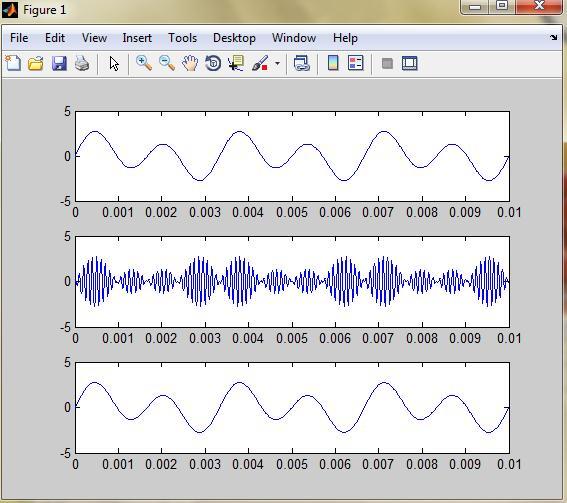
6 Amplitude demodulation z = amdemod(y,fc,fs) z = amdemod(y,fc,fs,ini_phase) z = amdemod(y,fc,fs,ini_phase,carramp) z = amdemod(y,fc,fs,ini_phase,carramp,num,den) z = amdemod(y,fc,fs) demodulates the amplitude modulated signal y from a carrier signal with frequency Fc (Hz). The carrier signal and y have sample frequency Fs (Hz). The modulated signal y has zero initial phase and zero carrier amplitude, so it represents suppressed carrier modulation. The demodulation process uses the lowpass filter specified by [num,den] = butter(5,fc*2/fs). Note The Fc and Fs arguments must satisfy Fs > 2(Fc + BW), where BW is the bandwidth of the original signal that was modulated. z = amdemod(y,fc,fs,ini_phase) specifies the initial phase of the modulated signal in radians. z = amdemod(y,fc,fs,ini_phase,carramp) demodulates a signal that was created via transmitted carrier modulation instead of suppressed carrier modulation. carramp is the carrier amplitude of the modulated signal. z = amdemod(y,fc,fs,ini_phase,carramp,num,den) specifies the numerator and denominator of the lowpass filter used in the demodulation. Examples The code below illustrates the use of a nondefault filter. t =.01; Fc = 10000; Fs = 80000; t = [0:1/Fs:0.01]'; s = sin(2*pi*300*t)+2*sin(2*pi*600*t); % Original signal [num,den] = butter(10,fc*2/fs); % Lowpass filter y1 = ammod(s,fc,fs); % Modulate. s1 = amdemod(y1,fc,fs,0,0,num,den); % Demodulate. subplot(3,1,1) plot(t,s) % befor modlating subplot(3,1,2) plot(t,y1) % after modlating subplot(3,1,3) plot(t,s1) % after De modlating

7
 mc=cos(2*pi*fc*t) Fsend=(A+mt).")
8 f(t)=m(t)*cos(2*pi*fc) clc clear fm=1; fc=1000; A=0; t=0:pi/40:10; mt=cos(2*pi*fm*t) mc=cos(2*pi*fc*t) Fsend=(A+mt).*mc plot(t, Fsend) Double side band-sc A=0
 and sampling rate Fs (Hz), where Fs must be at least 2*Fc. The freqdev argument is the frequency deviation constant (Hz) of the modulated signal.")
9 Frequency modulation y = fmmod(x,fc,fs,freqdev) y = fmmod(x,fc,fs,freqdev,ini_phase) y = fmmod(x,fc,fs,freqdev) modulates the message signal x using frequency modulation. The carrier signal has frequency Fc (Hz) and sampling rate Fs (Hz), where Fs must be at least 2*Fc. The freqdev argument is the frequency deviation constant (Hz) of the modulated signal. y = fmmod(x,fc,fs,freqdev,ini_phase) specifies the initial phase of the modulated signal, in radians. Examples Example: let input signal is x = sin(2*pi*300*t)+2*sin(2*pi*600 *t) and (fc=10,fs=100, Frequency deviation=50) find FM modulated Fs = 1000; % Sampling rate of signal Fc = 10; % Carrier frequency t = [0:Fs]'/Fs; % Sampling times x = sin(2*pi*300*t)+2*sin(2*pi*600*t); dev = 50; % Frequency deviation in modulated signal y = fmmod(x,fc,fs,dev); % Modulate both channels. plot(t,y)
10 The code below modulates a multichannel signal using fmmod and demodulates it Fs = 8000; % Sampling rate of signal Fc = 3000; % Carrier frequency t = [0:Fs]'/Fs; % Sampling times s1 = sin(2*pi*300*t)+2*sin(2*pi*600*t); % Channel 1 s2 = sin(2*pi*150*t)+2*sin(2*pi*900*t); % Channel 2 x = [s1,s2]; % Two-channel signal dev = 50; % Frequency deviation in modulated signal y = fmmod(x,fc,fs,dev); % Modulate both channels. z = fmdemod(y,fc,fs,dev); % Demodulate both channels. Frequency demodulation z = fmdemod(y,fc,fs,freqdev) z = fmdemod(y,fc,fs,freqdev,ini_phase) z = fmdemod(y,fc,fs,freqdev) demodulates the modulating signal z from the carrier signal using frequency demodulation. The carrier signal has frequency Fc (Hz) and sampling rate Fs (Hz), where Fs must be at least 2*Fc. The freqdev argument is the frequency deviation (Hz) of the modulated signal y. z = fmdemod(y,fc,fs,freqdev,ini_phase) specifies the initial phase of the modulated signal, in radians. Example: signal that input to system is x = sin(2*pi*300*t)+2*sin(2*pi*600*t) that (fc=10,fs=1000) find Fm mod and Demod Fs = 1000; % Sampling rate of signal Fc = 10; % Carrier frequency t = [0:Fs]'/Fs; % Sampling times x = sin(2*pi*300*t)+2*sin(2*pi*600*t); % Channel 1 dev = 50; % Frequency deviation in modulated signal y = fmmod(x,fc,fs,dev); % Modulate both channels. yd = fmdemod(y,fc,fs,dev ); % Modulate both channels. subplot(3,1,1) plot(t,x) % befor modlating subplot(3,1,2) plot(t,y) % after modlating subplot(3,1,3) plot(t,yd) % after De modulating
 and sampling rate Fs (hertz), where Fs must be at least 2*Fc. The phasedev argument is the phase deviation of the modulated signal in radians.")
11 Phase modulation y = pmmod(x,fc,fs,phasedev) y = pmmod(x,fc,fs,phasedev,ini_phase) y = pmmod(x,fc,fs,phasedev) modulates the message signal x using phase modulation. The carrier signal has frequency Fc (hertz) and sampling rate Fs (hertz), where Fs must be at least 2*Fc. The phasedev argument is the phase deviation of the modulated signal in radians. y = pmmod(x,fc,fs,phasedev,ini_phase) specifies the initial phase of the modulated signal in radians.
, where Fs must be at least 2*Fc. The phasedev argument is the phase deviation of the modulated signal, in radians.")
12 Phase demodulation z = pmdemod(y,fc,fs,phasedev) z = pmdemod(y,fc,fs,phasedev,ini_phase) z = pmdemod(y,fc,fs,phasedev) demodulates the phase-modulated signal y at the carrier frequency Fc (hertz). z and the carrier signal have sampling rate Fs (hertz), where Fs must be at least 2*Fc. The phasedev argument is the phase deviation of the modulated signal, in radians. z = pmdemod(y,fc,fs,phasedev,ini_phase) specifies the initial phase of the modulated signal, in radians. Representing Analog Signals To modulate an analog signal using this toolbox, start with a real message signal and a sampling rate Fs in hertz. Represent the signal using a vector x, the entries of which give the signal's values in time increments of 1/Fs. Alternatively, you can use a matrix to represent a multichannel signal, where each column of the matrix represents one channel. For example, if t measures time in seconds, then the vector x below is the result of sampling a sine wave 8000 times per second for 0.1 seconds. The vector y represents the modulated signal. Fs = 8000; % Sampling rate is 8000 samples per second. Fc = 300; % Carrier frequency in Hz t = [0:.1*Fs]'/Fs; % Sampling times for.1 second x = sin(20*pi*t); % Representation of the signal y = ammod(x,fc,fs); % Modulate x to produce y. figure; subplot(2,1,1); plot(t,x); % Plot x on top. subplot(2,1,2); plot(t,y)% Plot y below.
, sin(20*pi*t+pi/8)]; Analog Modulation Example This example illustrates the basic format of the analog modulation and demodulation functions.")
13 As a multichannel example, the code below defines a two-channel signal in which one channel is a sinusoid with zero initial phase and the second channel is a sinusoid with an initial phase of pi/8. Fs = 8000; t = [0:.1*Fs]'/Fs; x = [sin(20*pi*t), sin(20*pi*t+pi/8)]; Analog Modulation Example This example illustrates the basic format of the analog modulation and demodulation functions. Although the example uses phase modulation, most elements of this example apply to other analog modulation techniques as well. The example samples an analog signal and modulates it. Then it simulates an additive white Gaussian noise (AWGN) channel, demodulates the received signal, and plots the original and demodulated signals. % Prepare to sample a signal for two seconds, % at a rate of 100 samples per second. Fs = 100; % Sampling rate t = [0:2*Fs+1]'/Fs; % Time points for sampling % Create the signal, a sum of sinusoids. x = sin(2*pi*t) + sin(4*pi*t); Fc = 10; % Carrier frequency in modulation phasedev = pi/2; % Phase deviation for phase modulation y = pmmod(x,fc,fs,phasedev); % Modulate. y = awgn(y,10,'measured',103); % Add noise. z = pmdemod(y,fc,fs,phasedev); % Demodulate. % Plot the original and recovered signals. figure; plot(t,x,'k-',t,z,'g-'); legend('original signal','recovered signal');
14 ssbmod - Single sideband amplitude modulation y = ssbmod(x,fc,fs) y = ssbmod(x,fc,fs,ini_phase) y = ssbmod(x,fc,fs,ini_phase,'upper') y = ssbmod(x,fc,fs) uses the message signal x to modulate a carrier signal with frequency Fc (Hz) using single sideband amplitude modulation in which the lower sideband is the desired sideband. The carrier signal and x have sample frequency Fs (Hz). The modulated signal has zero initial phase. y = ssbmod(x,fc,fs,ini_phase) specifies the initial phase of the modulated signal in radians. y = ssbmod(x,fc,fs,ini_phase,'upper') uses the upper sideband as the desired sideband. ssbdemod - Single sideband amplitude demodulation z = ssbdemod(y,fc,fs) z = ssbdemod(y,fc,fs,ini_phase) z = ssbdemod(y,fc,fs,ini_phase,num,den) For All es z = ssbdemod(y,fc,fs) demodulates the single sideband amplitude modulated signal y from the carrier signal having frequency Fc (Hz). The carrier signal and y have sampling rate Fs (Hz). The modulated signal has zero initial phase, and can be an upper- or lower-sideband signal. The demodulation process uses the lowpass filter specified by [num,den] = butter(5,fc*2/fs). Note The Fc and Fs arguments must satisfy Fs > 2(Fc + BW), where BW is the bandwidth of the original signal that was modulated.
 specifies the numerator and denominator of the lowpass filter used in the demodulation.")
15 z = ssbdemod(y,fc,fs,ini_phase) specifies the initial phase of the modulated signal in radians. z = ssbdemod(y,fc,fs,ini_phase,num,den) specifies the numerator and denominator of the lowpass filter used in the demodulation. Examples The code below shows that ssbdemod can demodulate an upper-sideband or lowersideband signal. Fc = 12000; Fs = ; t = [0:1/Fs:0.01]'; s = sin(2*pi*300*t)+2*sin(2*pi*600*t); y1 = ssbmod(s,fc,fs,0); % Lower-sideband modulated signal y2 = ssbmod(s,fc,fs,0,'upper'); % Upper-sideband modulated signal s1 = ssbdemod(y1,fc,fs); % Demodulate lower sideband s2 = ssbdemod(y2,fc,fs); % Demodulate upper sideband % Plot results to show that the curves overlap. figure; plot(t,s1,'r-',t,s2,'k--'); legend('demodulation of upper sideband','demodulation of lower sideband')
EXPERIMENT Amplitude Modulation. a) ammod: For amplitude modulation. b) amdemod: For amplitude de modulation. 2. Frequency Modulation
 ammod: For amplitude modulation. b) amdemod: For amplitude de modulation. 2. Frequency Modulation") EXPERIMENT 1 AIM: To study various Analog modulation techniques using Matlab. Command Used: 1. Amplitude Modulation a) ammod: For amplitude modulation y = ammod(x,fc,fs) It uses the message signal x to
EXPERIMENT 1 AIM: To study various Analog modulation techniques using Matlab. Command Used: 1. Amplitude Modulation a) ammod: For amplitude modulation y = ammod(x,fc,fs) It uses the message signal x to
ECEGR Lab #8: Introduction to Simulink
 Page 1 ECEGR 317 - Lab #8: Introduction to Simulink Objective: By: Joe McMichael This lab is an introduction to Simulink. The student will become familiar with the Help menu, go through a short example,
EEL 4350 Principles of Communication Project 2 Due Tuesday, February 10 at the Beginning of Class
 EEL 4350 Principles of Communication Project 2 Due Tuesday, February 10 at the Beginning of Class Description In this project, MATLAB and Simulink are used to construct a system experiment. The experiment
Lab 1: Analog Modulations
 Lab 1: Analog Modulations October 20, 2017 This lab contains two parts: for the first part you will perform simulation entirely in MATLAB, for the second part you will use a hardware device to interface
Lab 1: Analog Modulations
 Lab 1: Analog Modulations Due: October 11, 2018 This lab contains two parts: for the first part you will perform simulation entirely in MATLAB, for the second part you will use a hardware device to interface
UNIVERSITY OF WARWICK
 UNIVERSITY OF WARWICK School of Engineering ES905 MSc Signal Processing Module (2010) AM SIGNALS AND FILTERING EXERCISE Deadline: This is NOT for credit. It is best done before the first assignment. You
EXPERIMENT 4 INTRODUCTION TO AMPLITUDE MODULATION SUBMITTED BY
 EXPERIMENT 4 INTRODUCTION TO AMPLITUDE MODULATION SUBMITTED BY NAME:. STUDENT ID:.. ROOM: INTRODUCTION TO AMPLITUDE MODULATION Purpose: The objectives of this laboratory are:. To introduce the spectrum
Amplitude Modulation Chapter 2. Modulation process
 Question 1 Modulation process Modulation is the process of translation the baseband message signal to bandpass (modulated carrier) signal at frequencies that are very high compared to the baseband frequencies.
Introduction to Simulink Assignment Companion Document
 Introduction to Simulink Assignment Companion Document Implementing a DSB-SC AM Modulator in Simulink The purpose of this exercise is to explore SIMULINK by implementing a DSB-SC AM modulator. DSB-SC AM
UNIVERSITY OF WARWICK
 UNIVERSITY OF WARWICK School of Engineering ES905 MSc Signal Processing Module (2004) ASSIGNMENT 1 In this assignment, you will use the MATLAB package. In Part (A) you will design some FIR filters and
Faculty of Engineering Electrical Engineering Department Communication Engineering I Lab (EELE 3170) Eng. Adam M. Hammad
 Eng. Adam M. Hammad") Faculty of Engineering Electrical Engineering Department Communication Engineering I Lab (EELE 3170) Eng. Adam M. Hammad EXPERIMENT #5 DSB-SC AND SSB MODULATOR Theory The amplitude-modulated signal is
Faculty of Engineering Electrical Engineering Department Communication Engineering I Lab (EELE 3170) Eng. Adam M. Hammad EXPERIMENT #5 DSB-SC AND SSB MODULATOR Theory The amplitude-modulated signal is
Electrical & Computer Engineering Technology
 Electrical & Computer Engineering Technology EET 419C Digital Signal Processing Laboratory Experiments by Masood Ejaz Experiment # 1 Quantization of Analog Signals and Calculation of Quantized noise Objective:
DSP First. Laboratory Exercise #7. Everyday Sinusoidal Signals
 DSP First Laboratory Exercise #7 Everyday Sinusoidal Signals This lab introduces two practical applications where sinusoidal signals are used to transmit information: a touch-tone dialer and amplitude
UNIT 1 QUESTIONS WITH ANSWERS
 UNIT 1 QUESTIONS WITH ANSWERS 1. Define modulation? Modulation is a process by which some characteristics of high frequency carrier signal is varied in accordance with the instantaneous value of the modulating
SETTING UP A WIRELESS LINK USING ME1000 RF TRAINER KIT
 SETTING UP A WIRELESS LINK USING ME1000 RF TRAINER KIT Introduction S Kumar Reddy Naru ME Signal Processing S. R. No - 05812 The aim of the project was to try and set up a point to point wireless link.
Project 2 - Speech Detection with FIR Filters
 Project 2 - Speech Detection with FIR Filters ECE505, Fall 2015 EECS, University of Tennessee (Due 10/30) 1 Objective The project introduces a practical application where sinusoidal signals are used to
Outline. Communications Engineering 1
 Outline Introduction Signal, random variable, random process and spectra Analog modulation Analog to digital conversion Digital transmission through baseband channels Signal space representation Optimal
CHAPTER 3 Noise in Amplitude Modulation Systems
 CHAPTER 3 Noise in Amplitude Modulation Systems NOISE Review: Types of Noise External (Atmospheric(sky),Solar(Cosmic),Hotspot) Internal(Shot, Thermal) Parameters of Noise o Signal to Noise ratio o Noise
Experiment 8: Sampling
 Prepared By: 1 Experiment 8: Sampling Objective The objective of this Lab is to understand concepts and observe the effects of periodically sampling a continuous signal at different sampling rates, changing
Software Simulation of Pulse Time Modulation Techniques
 Case Study Software Simulation of Pulse Time Modulation Techniques Introduction In recent years we have seen a growing interest in application of software simulation in communication engineering. With
ADC Clock Jitter Model, Part 2 Random Jitter
 db ADC Clock Jitter Model, Part 2 Random Jitter In Part 1, I presented a Matlab function to model an ADC with jitter on the sample clock, and applied it to examples with deterministic jitter. Now we ll
LAB 2 SPECTRUM ANALYSIS OF PERIODIC SIGNALS
 Eastern Mediterranean University Faculty of Engineering Department of Electrical and Electronic Engineering EENG 360 Communication System I Laboratory LAB 2 SPECTRUM ANALYSIS OF PERIODIC SIGNALS General
ECE 3500: Fundamentals of Signals and Systems (Fall 2014) Lab 4: Binary Phase-Shift Keying Modulation and Demodulation
 Lab 4: Binary Phase-Shift Keying Modulation and Demodulation") ECE 3500: Fundamentals of Signals and Systems (Fall 2014) Lab 4: Binary Phase-Shift Keying Modulation and Demodulation Files necessary to complete this assignment: none Deliverables Due: Before your assigned
ECE 3500: Fundamentals of Signals and Systems (Fall 2014) Lab 4: Binary Phase-Shift Keying Modulation and Demodulation Files necessary to complete this assignment: none Deliverables Due: Before your assigned
Title: Pulse Amplitude Modulation.
 Title: Pulse Amplitude Modulation. AIM Write a program to take input Frequency of Message Signal and find out the Aliased and Anti-Aliased wave, and also the Carrier Signal, Message Signal and their Fourier
Noise Simulation and Reduction in AM-SSB Radio Systems Thiago D. Olson, Zi Ling, and Mohammad Naquiddin A. Razak
 1 Noise Simulation and Reduction in AM-SSB Radio Systems Thiago D. Olson, Zi Ling, and Mohammad Naquiddin A. Razak Abstract Ham radio transmission distance is affected by many different external sources.
(b) What are the differences between FM and PM? (c) What are the differences between NBFM and WBFM? [9+4+3]
![(b) What are the differences between FM and PM? (c) What are the differences between NBFM and WBFM? [9+4+3]](/thumbs/85/91561193.jpg "(b) What are the differences between FM and PM? (c) What are the differences between NBFM and WBFM? [9+4+3]") Code No: RR220401 Set No. 1 1. (a) The antenna current of an AM Broadcast transmitter is 10A, if modulated to a depth of 50% by an audio sine wave. It increases to 12A as a result of simultaneous modulation
Code No: RR220401 Set No. 1 1. (a) The antenna current of an AM Broadcast transmitter is 10A, if modulated to a depth of 50% by an audio sine wave. It increases to 12A as a result of simultaneous modulation
L A B 3 : G E N E R A T I N G S I N U S O I D S
 L A B 3 : G E N E R A T I N G S I N U S O I D S NAME: DATE OF EXPERIMENT: DATE REPORT SUBMITTED: 1/7 1 THEORY DIGITAL SIGNAL PROCESSING LABORATORY 1.1 GENERATION OF DISCRETE TIME SINUSOIDAL SIGNALS IN
Islamic University of Gaza. Faculty of Engineering Electrical Engineering Department Spring-2011
 Islamic University of Gaza Faculty of Engineering Electrical Engineering Department Spring-2011 DSP Laboratory (EELE 4110) Lab#4 Sampling and Quantization OBJECTIVES: When you have completed this assignment,
ES442 Final Project AM & FM De/Modulation Using SIMULINK
 ES442 Final Project AM & FM De/Modulation Using SIMULINK Goal: 1. Understand the basics of SIMULINK and how it works within MATLAB. 2. Be able to create, configure and run a simple model. 3. Create a subsystem.
Amplitude Modulation, II
 Amplitude Modulation, II Single sideband modulation (SSB) Vestigial sideband modulation (VSB) VSB spectrum Modulator and demodulator NTSC TV signsals Quadrature modulation Spectral efficiency Modulator
Amplitude Modulation. Ahmad Bilal
 Amplitude Modulation Ahmad Bilal 5-2 ANALOG AND DIGITAL Analog-to-analog conversion is the representation of analog information by an analog signal. Topics discussed in this section: Amplitude Modulation
SAMPLING AND RECONSTRUCTING SIGNALS
 CHAPTER 3 SAMPLING AND RECONSTRUCTING SIGNALS Many DSP applications begin with analog signals. In order to process these analog signals, the signals must first be sampled and converted to digital signals.
The figures and the logic used for the MATLAB are given below.
 MATLAB FIGURES & PROGRAM LOGIC: Transmitter: The figures and the logic used for the MATLAB are given below. Binary Data Sequence: For our project we assume that we have the digital binary data stream.
ELT COMMUNICATION THEORY
 ELT 41307 COMMUNICATION THEORY Matlab Exercise #1 Sampling, Fourier transform, Spectral illustrations, and Linear filtering 1 SAMPLING The modeled signals and systems in this course are mostly analog (continuous
EE4512 Analog and Digital Communications Chapter 6. Chapter 6 Analog Modulation and Demodulation
 Chapter 6 Analog Modulation and Demodulation Chapter 6 Analog Modulation and Demodulation Amplitude Modulation Pages 306-309 309 The analytical signal for double sideband, large carrier amplitude modulation
Attia, John Okyere. Plotting Commands. Electronics and Circuit Analysis using MATLAB. Ed. John Okyere Attia Boca Raton: CRC Press LLC, 1999
 Attia, John Okyere. Plotting Commands. Electronics and Circuit Analysis using MATLAB. Ed. John Okyere Attia Boca Raton: CRC Press LLC, 1999 1999 by CRC PRESS LLC CHAPTER TWO PLOTTING COMMANDS 2.1 GRAPH
DIGITAL COMMUNICATIONS (INTRODUCTION TO MULTISIM SOFTWARE)
") PROJECT 1B DIGITAL COMMUNICATIONS (INTRODUCTION TO MULTISIM SOFTWARE) (i) FSK SYSTEM (MODULATOR / DEMODULATOR) Abstract: In this project, students are required to design a complete circuit of FSK SYSTEM.
PROJECT 1B DIGITAL COMMUNICATIONS (INTRODUCTION TO MULTISIM SOFTWARE) (i) FSK SYSTEM (MODULATOR / DEMODULATOR) Abstract: In this project, students are required to design a complete circuit of FSK SYSTEM.
Exercise 2: FM Detection With a PLL
 Phase-Locked Loop Analog Communications Exercise 2: FM Detection With a PLL EXERCISE OBJECTIVE When you have completed this exercise, you will be able to explain how the phase detector s input frequencies
Code No: R Set No. 1
 Code No: R05220405 Set No. 1 II B.Tech II Semester Regular Examinations, Apr/May 2007 ANALOG COMMUNICATIONS ( Common to Electronics & Communication Engineering and Electronics & Telematics) Time: 3 hours
 Modulations Analog Modulations Amplitude modulation (AM) Linear modulation Frequency modulation (FM) Phase modulation (PM) cos Angle modulation FM PM Digital Modulations ASK FSK PSK MSK MFSK QAM PAM Etc.
Figure 1: Block diagram of Digital signal processing
 Experiment 3. Digital Process of Continuous Time Signal. Introduction Discrete time signal processing algorithms are being used to process naturally occurring analog signals (like speech, music and images).
Discrete-Time Signal Processing (DTSP) v14
 v14") EE 392 Laboratory 5-1 Discrete-Time Signal Processing (DTSP) v14 Safety - Voltages used here are less than 15 V and normally do not present a risk of shock. Objective: To study impulse response and the
EE 392 Laboratory 5-1 Discrete-Time Signal Processing (DTSP) v14 Safety - Voltages used here are less than 15 V and normally do not present a risk of shock. Objective: To study impulse response and the
Angle Modulated Systems
 Angle Modulated Systems Angle of carrier signal is changed in accordance with instantaneous amplitude of modulating signal. Two types Frequency Modulation (FM) Phase Modulation (PM) Use Commercial radio
ADC Clock Jitter Model, Part 1 Deterministic Jitter
 ADC Clock Jitter Model, Part 1 Deterministic Jitter Analog to digital converters (ADC s) have several imperfections that effect communications signals, including thermal noise, differential nonlinearity,
FM Superheterodyne Receiver
 EE321 Final Project Chun-Hao Lo XiaoKai Sun Background: FM Superheterodyne Receiver Superheterodyne Receiver is the receiver that convert a received signal from the transmitter to an intermediate frequency.
ECE 5650/4650 MATLAB Project 1
 This project is to be treated as a take-home exam, meaning each student is to due his/her own work. The project due date is 4:30 PM Tuesday, October 18, 2011. To work the project you will need access to
ECE 3500: Fundamentals of Signals and Systems (Fall 2015) Lab 4: Binary Phase-Shift Keying Modulation and Demodulation
 Lab 4: Binary Phase-Shift Keying Modulation and Demodulation") ECE 500: Fundamentals of Signals and Systems (Fall 2015) Lab 4: Binary Phase-Shift Keying Modulation and Demodulation Files necessary to complete this assignment: none Deliverables Due: Before Dec. 18th
ECE 500: Fundamentals of Signals and Systems (Fall 2015) Lab 4: Binary Phase-Shift Keying Modulation and Demodulation Files necessary to complete this assignment: none Deliverables Due: Before Dec. 18th
SIR PADAMPAT SINGHANIA UNIVERSITY UDAIPUR Sample Question Paper for Ph.D. (Electronics & Communication Engineering) SPSAT 18
 SPSAT 18") INSTRUCTIONS SIR PADAMPAT SINGHANIA UNIVERSITY UDAIPUR Sample Question Paper for Ph.D. (Electronics & Communication Engineering) SPSAT 18 The test is 60 minutes long and consists of 40 multiple choice
INSTRUCTIONS SIR PADAMPAT SINGHANIA UNIVERSITY UDAIPUR Sample Question Paper for Ph.D. (Electronics & Communication Engineering) SPSAT 18 The test is 60 minutes long and consists of 40 multiple choice
Amplitude Modulated Systems
 Amplitude Modulated Systems Communication is process of establishing connection between two points for information exchange. Channel refers to medium through which message travels e.g. wires, links, or
Memorial University of Newfoundland Faculty of Engineering and Applied Science. Lab Manual
 Memorial University of Newfoundland Faculty of Engineering and Applied Science Engineering 6871 Communication Principles Lab Manual Fall 2014 Lab 1 AMPLITUDE MODULATION Purpose: 1. Learn how to use Matlab
 UNIT I FUNDAMENTALS OF ANALOG COMMUNICATION Introduction In the Microbroadcasting services, a reliable radio communication system is of vital importance. The swiftly moving operations of modern communities
Problems from the 3 rd edition
 (2.1-1) Find the energies of the signals: a) sin t, 0 t π b) sin t, 0 t π c) 2 sin t, 0 t π d) sin (t-2π), 2π t 4π Problems from the 3 rd edition Comment on the effect on energy of sign change, time shifting
5625 Chapter 4. April 7, Bandwidth Calculation 4 Bandlimited Noise PM and FM... 4
 5625 Chapter 4 April 7, 2016 Contents Sinusoidal Angle Modulation Spectra 2 Plot Spectra.............................................. 2 Bandwidth Calculation 4 Bandlimited Noise PM and FM...................................
Design IIR Filters Using Cascaded Biquads
 Design IIR Filters Using Cascaded Biquads This article shows how to implement a Butterworth IIR lowpass filter as a cascade of second-order IIR filters, or biquads. We ll derive how to calculate the coefficients
Simulink Implementation of Amplitude Modulation Technique using Matlab
 Simulink Implementation of Amplitude Modulation Technique using Matlab Mr. Ranjeet R. Suryawanshi 1, Mr. Vikas D. Patil 2 1,2Assistant Professor, Department of Electronics & Telecommunication Engineering,
1.5 The voltage V is given as V=RI, where R and I are resistance matrix and I current vector. Evaluate V given that
 Sheet (1) 1.1 The voltage across a discharging capacitor is v(t)=10(1 e 0.2t ) Generate a table of voltage, v(t), versus time, t, for t = 0 to 50 seconds with increment of 5 s. 1.2 Use MATLAB to evaluate
CME 312-Lab Communication Systems Laboratory
 Objective: By the end of this experiment, the student should be able to: 1. Demonstrate the Modulation and Demodulation of the AM. 2. Observe the relation between modulation index and AM signal envelope.
Speech, music, images, and video are examples of analog signals. Each of these signals is characterized by its bandwidth, dynamic range, and the
 Speech, music, images, and video are examples of analog signals. Each of these signals is characterized by its bandwidth, dynamic range, and the nature of the signal. For instance, in the case of audio
Signal Generators for Anritsu RF and Microwave Handheld Instruments
 Measurement Guide Signal Generators for Anritsu RF and Microwave Handheld Instruments BTS Master Spectrum Master Tracking Generator Option 20 Vector signal Generator Option 23 Anritsu Company 490 Jarvis
Sampling and Reconstruction of Analog Signals
 Sampling and Reconstruction of Analog Signals Chapter Intended Learning Outcomes: (i) Ability to convert an analog signal to a discrete-time sequence via sampling (ii) Ability to construct an analog signal
World Journal of Engineering Research and Technology WJERT
 wjert, 2017, Vol. 3, Issue 2, 185-197 Original Article ISSN 2454-695X Susanchi et al. WJERT www.wjert.org SJIF Impact Factor: 4.326 DESIGN AND SIMULATION OF DOUBLE SIDE BAND SUPPRESSED CARRIER MODEL USING
EE470 Electronic Communication Theory Exam II
 EE470 Electronic Communication Theory Exam II Open text, closed notes. For partial credit, you must show all formulas in symbolic form and you must work neatly!!! Date: November 6, 2013 Name: 1. [16%]
Experiment 4 Sampling and Aliasing
 Experiment 4 ampling and Aliasing INTRODUCTION One of the basic processes found in digital communications is sampling. Continuous signals from analog sources such as voice, music, video or other forms
Presentation Outline. Advisors: Dr. In Soo Ahn Dr. Thomas L. Stewart. Team Members: Luke Vercimak Karl Weyeneth. Karl. Luke
 Bradley University Department of Electrical and Computer Engineering Senior Capstone Project Presentation May 2nd, 2006 Team Members: Luke Vercimak Karl Weyeneth Advisors: Dr. In Soo Ahn Dr. Thomas L.
UNIT-I AMPLITUDE MODULATION (2 Marks Questions and Answers)
") UNIT-I AMPLITUDE MODULATION (2 Marks Questions and Answers) 1. Define modulation? Modulation is a process by which some characteristics of high frequency carrier Signal is varied in accordance with the
UNIT-I AMPLITUDE MODULATION (2 Marks Questions and Answers) 1. Define modulation? Modulation is a process by which some characteristics of high frequency carrier Signal is varied in accordance with the
Exercise 1: Frequency and Phase Modulation
 Exercise 1: Frequency and Phase Modulation EXERCISE OBJECTIVE When you have completed this exercise, you will be able to describe frequency modulation and an FM circuit. You will also be able to describe
Communication Engineering Prof. Surendra Prasad Department of Electrical Engineering Indian Institute of Technology, Delhi
 Communication Engineering Prof. Surendra Prasad Department of Electrical Engineering Indian Institute of Technology, Delhi Lecture - 16 Angle Modulation (Contd.) We will continue our discussion on Angle
DT Filters 2/19. Atousa Hajshirmohammadi, SFU
 1/19 ENSC380 Lecture 23 Objectives: Signals and Systems Fourier Analysis: Discrete Time Filters Analog Communication Systems Double Sideband, Sub-pressed Carrier Modulation (DSBSC) Amplitude Modulation
Swedish College of Engineering and Technology Rahim Yar Khan
 PRACTICAL WORK BOOK Telecommunication Systems and Applications (TL-424) Name: Roll No.: Batch: Semester: Department: Swedish College of Engineering and Technology Rahim Yar Khan Introduction Telecommunication
FACULTY OF ENGINEERING LAB SHEET ETN3046 ANALOG AND DIGITAL COMMUNICATIONS TRIMESTER 1 (2018/2019) ADC2 Digital Carrier Modulation
 ADC2 Digital Carrier Modulation") FACULTY OF ENGINEERING LAB SHEET ETN3046 ANALOG AND DIGITAL COMMUNICATIONS TRIMESTER 1 (2018/2019) ADC2 Digital Carrier Modulation TC Chuah (2018 July) Page 1 ADC2 Digital Carrier Modulation with MATLAB
FACULTY OF ENGINEERING LAB SHEET ETN3046 ANALOG AND DIGITAL COMMUNICATIONS TRIMESTER 1 (2018/2019) ADC2 Digital Carrier Modulation TC Chuah (2018 July) Page 1 ADC2 Digital Carrier Modulation with MATLAB
Massachusetts Institute of Technology Dept. of Electrical Engineering and Computer Science Spring Semester, Introduction to EECS 2
 Massachusetts Institute of Technology Dept. of Electrical Engineering and Computer Science Spring Semester, 2007 6.082 Introduction to EECS 2 Lab #3: Modulation and Filtering Goal:... 2 Instructions:...
Subcarrier Placement in a PCM-FM-FM/FM Modulation Scheme
 Subcarrier Placement in a PCM-FM-FM/FM Modulation Scheme presented to The International Foundation for Telemetering International Telemetering Conference '91 Student Paper Contest by Juliette Lyn Moser
DSP First. Laboratory Exercise #2. Introduction to Complex Exponentials
 DSP First Laboratory Exercise #2 Introduction to Complex Exponentials The goal of this laboratory is gain familiarity with complex numbers and their use in representing sinusoidal signals as complex exponentials.
Estimation of Predetection SNR of LMR Analog FM Signals Using PL Tone Analysis
 Estimation of Predetection SNR of LMR Analog FM Signals Using PL Tone Analysis Akshay Kumar akshay2@vt.edu Steven Ellingson ellingson@vt.edu Virginia Tech, Wireless@VT May 2, 2012 Table of Contents 1 Introduction
Experiment # 4. Frequency Modulation
 ECE 416 Fall 2002 Experiment # 4 Frequency Modulation 1 Purpose In Experiment # 3, a modulator and demodulator for AM were designed and built. In this experiment, another widely used modulation technique
BINARY PHASE SHIFT KEYING (BPSK) SIMULATION USING MATLAB
 SIMULATION USING MATLAB") BIARY PHASE SHIFT KEYIG (BPSK) SIMULATIO USIG MATLAB Stanimir Sadinov, Pesha Daneva, Panagiotis Kogias, Jordan Kanev and Kyriakos Ovaliadis Department KTT, Faculty of Electrical Engineering and Electronics,
BIARY PHASE SHIFT KEYIG (BPSK) SIMULATIO USIG MATLAB Stanimir Sadinov, Pesha Daneva, Panagiotis Kogias, Jordan Kanev and Kyriakos Ovaliadis Department KTT, Faculty of Electrical Engineering and Electronics,
Study of Analog Phase-Locked Loop (APLL)
") Laboratory Exercise 9. (Last updated: 18/1/013, Tamás Krébesz) Study of Analog Phase-Locked Loop (APLL) Required knowledge Operation principle of analog phase-locked-loop (APLL) Operation principle of
Laboratory Exercise 9. (Last updated: 18/1/013, Tamás Krébesz) Study of Analog Phase-Locked Loop (APLL) Required knowledge Operation principle of analog phase-locked-loop (APLL) Operation principle of
4.1 REPRESENTATION OF FM AND PM SIGNALS An angle-modulated signal generally can be written as
 1 In frequency-modulation (FM) systems, the frequency of the carrier f c is changed by the message signal; in phase modulation (PM) systems, the phase of the carrier is changed according to the variations
Analog Communication.
 Analog Communication Vishnu N V Tele is Greek for at a distance, and Communicare is latin for to make common. Telecommunication is the process of long distance communications. Early telecommunications
Massachusetts Institute of Technology Dept. of Electrical Engineering and Computer Science Fall Semester, Introduction to EECS 2
 Massachusetts Institute of Technology Dept. of Electrical Engineering and Computer Science Fall Semester, 2006 6.082 Introduction to EECS 2 Modulation and Demodulation Introduction A communication system
EECE 301 Signals & Systems Prof. Mark Fowler
 EECE 301 Signals & Systems Prof. Mark Fowler Note Set #16 C-T Signals: Using FT Properties 1/12 Recall that FT Properties can be used for: 1. Expanding use of the FT table 2. Understanding real-world concepts
B.Tech II Year II Semester (R13) Supplementary Examinations May/June 2017 ANALOG COMMUNICATION SYSTEMS (Electronics and Communication Engineering)
 Supplementary Examinations May/June 2017 ANALOG COMMUNICATION SYSTEMS (Electronics and Communication Engineering)") Code: 13A04404 R13 B.Tech II Year II Semester (R13) Supplementary Examinations May/June 2017 ANALOG COMMUNICATION SYSTEMS (Electronics and Communication Engineering) Time: 3 hours Max. Marks: 70 PART A
Code: 13A04404 R13 B.Tech II Year II Semester (R13) Supplementary Examinations May/June 2017 ANALOG COMMUNICATION SYSTEMS (Electronics and Communication Engineering) Time: 3 hours Max. Marks: 70 PART A
Modulation is the process of impressing a low-frequency information signal (baseband signal) onto a higher frequency carrier signal
 onto a higher frequency carrier signal") Modulation is the process of impressing a low-frequency information signal (baseband signal) onto a higher frequency carrier signal Modulation is a process of mixing a signal with a sinusoid to produce
Modulation is the process of impressing a low-frequency information signal (baseband signal) onto a higher frequency carrier signal Modulation is a process of mixing a signal with a sinusoid to produce
PLL EXERCISE. R3 16k C3. 2π π 0 π 2π
 PLL EXERCISE Φ in (S) PHASE DETECTOR + Kd - V d (S) R1 R2 C2 220k 10k 10 nf Φ o (S) VCO Kv S V c (S) R3 16k C3 1 nf V dem (S) VCO Characteristics Phase Detector Characteristics V d ave F o 150k +5V (H
CME312- LAB Manual DSB-SC Modulation and Demodulation Experiment 6. Experiment 6. Experiment. DSB-SC Modulation and Demodulation
 Experiment 6 Experiment DSB-SC Modulation and Demodulation Objectives : By the end of this experiment, the student should be able to: 1. Demonstrate the modulation and demodulation process of DSB-SC. 2.
AM Limitations. Amplitude Modulation II. DSB-SC Modulation. AM Modifications
 Lecture 6: Amplitude Modulation II EE 3770: Communication Systems AM Limitations AM Limitations DSB-SC Modulation SSB Modulation VSB Modulation Lecture 6 Amplitude Modulation II Amplitude modulation is
Waveforms and Spectra in NBFM Receiver
 Waveforms and Spectra in NBFM Receiver GNU radio was used to create the following NBFM receiver. The USRP with the RFX400 daughterboard was used to capture the signal. 64Ms/s 256Ks/s 32Ks/s 32Ks/s FPGA
Signal Processing Toolbox
 Signal Processing Toolbox Perform signal processing, analysis, and algorithm development Signal Processing Toolbox provides industry-standard algorithms for analog and digital signal processing (DSP).
page 7.51 Chapter 7, sections , pp Angle Modulation No Modulation (t) =2f c t + c Instantaneous Frequency 2 dt dt No Modulation
 =2f c t + c Instantaneous Frequency 2 dt dt No Modulation") page 7.51 Chapter 7, sections 7.1-7.14, pp. 322-368 Angle Modulation s(t) =A c cos[(t)] No Modulation (t) =2f c t + c s(t) =A c cos[2f c t + c ] Instantaneous Frequency f i (t) = 1 d(t) 2 dt or w i (t)
page 7.51 Chapter 7, sections 7.1-7.14, pp. 322-368 Angle Modulation s(t) =A c cos[(t)] No Modulation (t) =2f c t + c s(t) =A c cos[2f c t + c ] Instantaneous Frequency f i (t) = 1 d(t) 2 dt or w i (t)
DIGITAL FILTERING AND THE DFT
 DIGITAL FILTERING AND THE DFT Digital Linear Filters in the Receiver Discrete-time Linear System Tidbits DFT Tidbits Filter Design Tidbits idealized system Software Receiver Design Johnson/Sethares/Klein
Amplitude Modulation II
 Lecture 6: Amplitude Modulation II EE 3770: Communication Systems Lecture 6 Amplitude Modulation II AM Limitations DSB-SC Modulation SSB Modulation VSB Modulation Multiplexing Mojtaba Vaezi 6-1 Contents
BLOCK DIAGRAM: PULSE CODE MODULATION: FUNCTION GENERATOR CHECKER CIRCUIT DEMODULATED O/P TIMING
 BLOCK DIAGRAM: PULSE CODE MODULATION: FUNCTION GENERATOR CHECKER CIRCUIT DEMODULATED O/P TIMING LOGIC TIMING LOGIC PCM OUTPUT SAMPLE INPUT SIGNAL OUTPUT LOGIC LATCH DIGITAL TO ANALOG CONVERTER PAM O/P
Real and Complex Modulation
 Real and Complex Modulation TIPL 4708 Presented by Matt Guibord Prepared by Matt Guibord 1 What is modulation? Modulation is the act of changing a carrier signal s properties (amplitude, phase, frequency)
Solution Set for Mini-Project #2 on Octave Band Filtering for Audio Signals
 EE 313 Linear Signals & Systems (Fall 2018) Solution Set for Mini-Project #2 on Octave Band Filtering for Audio Signals Mr. Houshang Salimian and Prof. Brian L. Evans 1- Introduction (5 points) A finite
The quality of the transmission signal The characteristics of the transmission medium. Some type of transmission medium is required for transmission:
 Data Transmission The successful transmission of data depends upon two factors: The quality of the transmission signal The characteristics of the transmission medium Some type of transmission medium is
DEPARTMENT OF E.C.E.
 PVP SIDDHARTHA INSTITUTE OF TECHNOLOGY, KANURU, VIJAYAWADA-7 DEPARTMENT OF E.C.E. ANALOG COMMUNICATIONS LAB MANUAL Department of Electronics & Communication engineering Prasad V.Potluri Siddhartha Institute
Measuring Modulations
 I N S T I T U T E O F C O M M U N I C A T I O N E N G I N E E R I N G Telecommunications Laboratory Measuring Modulations laboratory guide Table of Contents 2 Measurement Tasks...3 2.1 Starting up the
TSEK02: Radio Electronics Lecture 2: Modulation (I) Ted Johansson, EKS, ISY
 Ted Johansson, EKS, ISY") TSEK02: Radio Electronics Lecture 2: Modulation (I) Ted Johansson, EKS, ISY An Overview of Modulation Techniques: chapter 3.1 3.3.1 2 Introduction (3.1) Analog Modulation Amplitude Modulation Phase and
TSEK02: Radio Electronics Lecture 2: Modulation (I) Ted Johansson, EKS, ISY An Overview of Modulation Techniques: chapter 3.1 3.3.1 2 Introduction (3.1) Analog Modulation Amplitude Modulation Phase and
cosω t Y AD 532 Analog Multiplier Board EE18.xx Fig. 1 Amplitude modulation of a sine wave message signal
 University of Saskatchewan EE 9 Electrical Engineering Laboratory III Amplitude and Frequency Modulation Objectives: To observe the time domain waveforms and spectra of amplitude modulated (AM) waveforms
Communication Engineering Prof. Surendra Prasad Department of Electrical Engineering Indian Institute of Technology, Delhi
 Communication Engineering Prof. Surendra Prasad Department of Electrical Engineering Indian Institute of Technology, Delhi Lecture - 10 Single Sideband Modulation We will discuss, now we will continue