Amplitude Modulation. Ahmad Bilal
|
|
|
- Rodger Riley
- 5 years ago
- Views:
Transcription

1 Amplitude Modulation Ahmad Bilal

2 5-2 ANALOG AND DIGITAL Analog-to-analog conversion is the representation of analog information by an analog signal. Topics discussed in this section: Amplitude Modulation Frequency Modulation Phase Modulation 5.2

3 Types of analog-to-analog modulation 5.3
4 Basics of Modulation In modulation we have two signals Message signal. Low frequency Low Energy Example voice Carrier Signal High frequency and energy
5 Basic of Modulation We know a signal with frequency can travel a large distance with small antenna size, where as a baseband signal is low in frequency and energy Question is what to do if we want to send our baseband signal to large distance
6 Answer Superimpose it
7
8
 in which its amplitude is changed (modulated)")
 causes the carriers")

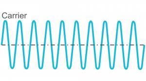
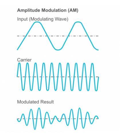
9 An AM signal is made up of a carrier (with constant frequency) in which its amplitude is changed (modulated) with respect to the input signal (modulating signal). The modulating signal (message signal) causes the carriers amplitude to change with time. This resulting shape of the carrier is called the envelope. Note the envelope has the shape of a sine wave.
10 Message Signal The modulating waveform can either be a single tone. This can be represented by a cosine waveform, or the modulating waveform could be a wide variety of frequencies Message signal may be represented as m (t) = M sin (ωmt) Where: modulating signal frequency in Hertz is equal to ωm / 2 π M is the carrier amplitude φ is the phase of the signal at the start of the reference time It is worth noting that normally the modulating signal frequency is well below that of the carrier frequency.
11 Carrier Signal Carrier signal is represented as C (t) = C sin (ωct) Where: carrier frequency in Hertz is equal to ωc / 2 π C is the carrier amplitude
12 The Modulated wave M(t) M(t)*c(t) C(t) C(t)
13 The Time and Frequency Analysis We know m(t)= M(w) When the signal is modulated we get m(t) X c(t) = Vm cos (ωmt) x cos (ωct) = ½ V m Cos ( ( m - c ) t ) + ½ V m Cos (( m + c )t)
14 Things to Note ½ V m Cos ( ( m - c ) t ) + ½ V m Cos (( m + c )t)) Frequency range has shifted Amplitude of signal have become half
15 Representation of any sinusoidal wave So cos(1000t) = pi (δ (w-1000)+ pi (δ (w+1000) π -1000Hz 1000Hz
16 Things to Note ½ V m Cos ( ( m - c ) t ) + ½ V m Cos (( m + c )t)) So lets say M(t) =cos 1000t and c(t)=10000t : Modulated signal will be ½ 1 Cos ( (-9000) t ) + ½ 1V m Cos ((11000)) Means in frequency domain signal will exist on hz and hz infrequency domain signal will exist on hz and hz Similarly in Fourier Mt*cos(wct) = ½ [M(wm+wc)+M(wm-wc)]
17 Things to Note M(t) =cos 1000t and c(t)=10000t The modulated signal will be ½ 1 Cos ( (-9000) t ) + ½ 1V m Cos ((11000)) Means in frequency domain signal will exist on hz and hz infrequency domain signal will exist on hz and hz π/ hz -9000Hz 9000Hz HZ
18 Things to Note π/ Hz 9000Hz Final Result of Modulated Signal Note the signal has exact two copies one with positive frequency components and other With negative frequency components
19 As the modulated signal consist of two copies of exact same signal. We may study any one, the properties for other will be same π/2 Wc-Wm Lower Side band Wc+Wm Upper side band Wc =10000 Hz 9000Hz Modulated signal is centered around Wc If we add message signal frequency to carrier frequency, we get upper and lower limit of signal Let these limits be called upper side band and Lower side band
20 The whole Picture
21 The Complete Picture As signal has two copies of low side band and upper side band. Thus the signal is called double side band with suppressed carrier Both copies contains exact information Upper side band and lower band also contain same information
22
23 Band width calculation Wc-Wm Wc+Wm 9000Hz Wc =10000 Hz The message signal had a bandwidth of 1000 hz Can u derive the bandwidth relation of message signal and modulated signals
24 A standard AM broadcast station is allowed to transmit modulating frequencies up to 5 khz. If the AM station is transmitting on a frequency of 980 khz, compute the maximum and minimum upper and lower sidebands and the total bandwidth occupied by the AM station.
25
26 Class Task : Synchronous Detection and Coherent Detection Modulated signal= ½ 1 Cos ( (-9000) t ) + ½ 1V m Cos ((11000)) Draw Frequency Domain spectrum for Modulated signal x cos t
27 Modulators Multiplier modulators Two signals are directly multiplied together. Very difficult to implement (non linear behavior ) Very expensive
28 Balanced Modulator
29 Also called non liner modulator NL represents any non linear devices that behaves as ax(t) +bx 2 (t) M(t) + cos(wct) ax(t) +bx 2 (t) am(t)+acos(wct)+ b(m 2 (t)+cos 2 (wc(t)+2m(t)cos(wc(t))) M(t) - cos(wct) ax(t) +bx 2 (t) am(t)-acos(wct)+ b(m 2 (t)+cos 2 (wc(t)-2m(t)cos(wc(t)))
30 Also called non liner modulator NL represents any non linear devices that behaves as ax(t) +bx 2 (t) am(t)+acos(wct)+ b(m 2 (t)+cos 2 (wc(t)+2m(t)cos(wc(t))) - am(t)-acos(wct)+ b(m 2 (t)+cos 2 (wc(t)-2m(t)cos(wc(t))) am(t)+acos(wct)+ b(m 2 (t)+bcos 2 (wc(t)+2bm(t)cos(wc(t))) -am(t)+acos(wct)-bm 2 (t)-bcos 2 (wc(t)+2bm(t)cos(wc(t))) =final Out put 2acos(wct(t))+4bm(t)(cos(wc(t))
31 Amplitude Modulation DSB 1. In last method, there was no carrier wave sent to, receiver. 2. Hence if the receiver does not know about the modulating frequency, it can not recover original signal. 3. The other alterative is to send carrier signal along with modulated signal to the receiver, so there is no requirement of generating carrier at receiver side. 4. How ever for sending carrier wave along with modulated waves, needs lot of power and energy. 5. Where DSB-SC is used and Where DSB is used
32 DSB = AM DSB method is generally what people refer to when they are talking about AM. The modulated signal is represented by. What will be the frequency domain representation
33 Choosing Values
34 Envelop Detection Condition A+m(t)>0
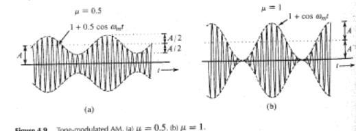
35 Modulation Index μ Amplitude of Modulating Signal Amplitude of Carrier Signal μ= Vm Vc Amplitude of carrier signal should always be greater than message signal. The value of modulation index is always between zero and 1 If value of μ > 1. This is called over modulation : loss of data
36 Effect mo Modulation Index
37
38
39 Preventing overmodulation is tricky. For example, at different times during voice transmission voices will go from low amplitude to high amplitude. Normally, the amplitude of the modulating signal is adjusted so that only the voice peaks produce 100 percent modulation. This prevents overmodulation and distortion. Automatic circuits called compression circuits solve this problem by amplifying the lower-level signals and suppressing or compressing the higher-level signals. The result is a higher average power output level without overmodulation. Distortion caused by overmodulation also produces adjacent channel interference.
40 Other Formulas for Calculating Modulating Index For any modulated wave, we may find, Vm and Vc as
41 Suppose that on an AM signal, the Vmax (p-p) value read from the graticule on the oscilloscope screen is 5.9 divisions and is Vmin (p-p) 1.2 divisions.
42 Power of AM Waves An AM signal is said to be made up of 3 components Carrier + LSB+ USB The Power of sideband depends on Modulation index Greater is modulation index, More is side band Power
43 For Power calculation, we need Peak Values RMS values. Can be obtained multiplying the voltage value to Using Power formula
44 Power of AM wave
45
46 if the carrier of an AM transmitter is 1000 W and it is modulated 100 percent (m = 1), the total AM power i
47 Solve for 70 percent modulated 250-W carrier, the total power in the composite AM signal is
48 Power Factor in Terms Of I Power can also be calculated in terms of current, as it is easy to measure the current across the know resistor/load. As we all know that P=I 2 R : So our equation will become P t =I t2 R Where I t is
49 Quick Example The total output power of an 85 percent modulated AM transmitter, whose unmodulated carrier current into a 50 Ohm antenna load is 10 Ampere Hmm easy Just Apply the formula I t =I c (1+(m 2 /2)) Where Ic = 10 m =0.85 I t =10 (1.36) = Amp NOW CALCULATE POWER
50 Find Modulation Factor
51 Find Modulation Factor I t =I c (1+(m 2 /2)) Where Ic = 10 I t =10 (1.36) = Amp NOW CALCULATE Modulation Index
52 Question
53 Question Remember you can also calculate via
54
55 The transmitter in Example 3-4 experiences an antenna current change from 4.8 A unmodulated to 5.1 A. What is the percentage of modulation?
56
57 Single Side Band In DSB the basic information is transmitted twice. (Practically speaking there is no advantage of doing so) So one side band may be suppressed Advantages 1. Occupy Less spectrum (more signals can be transmitted) 2. Strong signal (No power for double bands and carrier ) 3. Less fading
58 Single Side Band Typical AM Suppressed LSB FC USB
59 Disadvantage Demodulation depends upon the carrier being present. If the carrier is not present, then it must be regenerated at the receiver and reinserted into the signal. To faithfully recover the intelligence signal, the reinserted carrier must have the same phase and frequency as those of the original carrier. This is a difficult requirement. When SSB is used for voice transmission, the reinserted carrier can be made variable in, frequency so that it can be adjusted manually This is not possible with some kinds of data signals.
60 To solve this problem, a low-level carrier signal is sometimes transmitted along with the two sidebands in DSB or a single sideband in SSB. Because the carrier has a low power level, the essential benefits of SSB are retained, but a weak carrier is received so that it can be amplified and reinserted to recover the original information. Such a low-level carrier is referred to as a pilot carrier.
61 SSB Power In SSB one of the band is transmitted, either upper or lower. It has a ratio of 3:1 over AM Mean A 50W SSB transmitter will have same performance as of 150 W AM In SSB the power is expressed in terms of PEP, Peak Envelope Power.
62 SSB Power
63 Applications SSB Telephone systems Two way radio (for military apps) DSB FM and TV Audio Broad casting
64 ,Assume that a voice signal produces a 360-V, peakto-peak signal across a 50-V load. The rms voltage is times the peak value, and the peak value is onehalf the peak-to-peak voltage.
65 PEP in terms of I where Vs = amplifier supply voltage Imax =current peak A 450-V supply with a peak current of 0.8 A produces a what PEP in watts
66
67 Voice amplitude peaks are produced only when very loud sounds are generated during certain speech patterns or when some word or sound is emphasized. During normal speech levels, the input and output power levels are much less than the PEP level. The average power is typically only one-fourth to onethird of the PEP value with typical human speech
68 With a PEP of 240 W, the average power is only 60 to 80 W. Typical SSB transmitters are designed to handle only the average power level on a continuous basis, not the PEP.
69 An SSB transmitter produces a peak-to-peak voltage of 178 V across a 75-V antenna load. What is the PEP
70 An SSB transmitter has a 24-V dc power supply. On voice peaks the current achieves a maximum of 9.3 A. What is PEP What is average power of transmitter
Chapter 3. Amplitude Modulation Fundamentals
 Chapter 3 Amplitude Modulation Fundamentals Topics Covered 3-1: AM Concepts 3-2: Modulation Index and Percentage of Modulation 3-3: Sidebands and the Frequency Domain 3-4: AM Power 3-5: Single-Sideband
CHAPTER 2! AMPLITUDE MODULATION (AM)
") CHAPTER 2 AMPLITUDE MODULATION (AM) Topics 2-1 : AM Concepts 2-2 : Modulation Index and Percentage of Modulation 2-3 : Sidebands and the Frequency Domain 2-4 : Single-Sideband Modulation 2-5 : AM Power
CHAPTER 2 AMPLITUDE MODULATION (AM) Topics 2-1 : AM Concepts 2-2 : Modulation Index and Percentage of Modulation 2-3 : Sidebands and the Frequency Domain 2-4 : Single-Sideband Modulation 2-5 : AM Power
Amplitude Modulation Fundamentals
 3 chapter Amplitude Modulation Fundamentals In the modulation process, the baseband voice, video, or digital signal modifies another, higher-frequency signal called the carrier, which is usually a sine
AM Limitations. Amplitude Modulation II. DSB-SC Modulation. AM Modifications
 Lecture 6: Amplitude Modulation II EE 3770: Communication Systems AM Limitations AM Limitations DSB-SC Modulation SSB Modulation VSB Modulation Lecture 6 Amplitude Modulation II Amplitude modulation is
Amplitude Modulation II
 Lecture 6: Amplitude Modulation II EE 3770: Communication Systems Lecture 6 Amplitude Modulation II AM Limitations DSB-SC Modulation SSB Modulation VSB Modulation Multiplexing Mojtaba Vaezi 6-1 Contents
Amplitude Modulation Chapter 2. Modulation process
 Question 1 Modulation process Modulation is the process of translation the baseband message signal to bandpass (modulated carrier) signal at frequencies that are very high compared to the baseband frequencies.
Outline. Communications Engineering 1
 Outline Introduction Signal, random variable, random process and spectra Analog modulation Analog to digital conversion Digital transmission through baseband channels Signal space representation Optimal
Amplitude Modulation, II
 Amplitude Modulation, II Single sideband modulation (SSB) Vestigial sideband modulation (VSB) VSB spectrum Modulator and demodulator NTSC TV signsals Quadrature modulation Spectral efficiency Modulator
Code No: R Set No. 1
 Code No: R05220405 Set No. 1 II B.Tech II Semester Regular Examinations, Apr/May 2007 ANALOG COMMUNICATIONS ( Common to Electronics & Communication Engineering and Electronics & Telematics) Time: 3 hours
ELEC3242 Communications Engineering Laboratory Amplitude Modulation (AM)
") ELEC3242 Communications Engineering Laboratory 1 ---- Amplitude Modulation (AM) 1. Objectives 1.1 Through this the laboratory experiment, you will investigate demodulation of an amplitude modulated (AM)
ELEC3242 Communications Engineering Laboratory 1 ---- Amplitude Modulation (AM) 1. Objectives 1.1 Through this the laboratory experiment, you will investigate demodulation of an amplitude modulated (AM)
(b) What are the differences between FM and PM? (c) What are the differences between NBFM and WBFM? [9+4+3]
![(b) What are the differences between FM and PM? (c) What are the differences between NBFM and WBFM? [9+4+3]](/thumbs/85/91561193.jpg "(b) What are the differences between FM and PM? (c) What are the differences between NBFM and WBFM? [9+4+3]") Code No: RR220401 Set No. 1 1. (a) The antenna current of an AM Broadcast transmitter is 10A, if modulated to a depth of 50% by an audio sine wave. It increases to 12A as a result of simultaneous modulation
Code No: RR220401 Set No. 1 1. (a) The antenna current of an AM Broadcast transmitter is 10A, if modulated to a depth of 50% by an audio sine wave. It increases to 12A as a result of simultaneous modulation
Introduction. Amplitude Modulation System Angle Modulation System
 Introduction Amplitude Modulation System Angle Modulation System Frequency Modulation Phase Modulation Digital Communication Elements of Information Theory Advanced Communication Techniques 1 Tools for
Speech, music, images, and video are examples of analog signals. Each of these signals is characterized by its bandwidth, dynamic range, and the
 Speech, music, images, and video are examples of analog signals. Each of these signals is characterized by its bandwidth, dynamic range, and the nature of the signal. For instance, in the case of audio
Charan Langton, Editor
 Charan Langton, Editor SIGNAL PROCESSING & SIMULATION NEWSLETTER Baseband, Passband Signals and Amplitude Modulation The most salient feature of information signals is that they are generally low frequency.
UNIT-I AMPLITUDE MODULATION (2 Marks Questions and Answers)
") UNIT-I AMPLITUDE MODULATION (2 Marks Questions and Answers) 1. Define modulation? Modulation is a process by which some characteristics of high frequency carrier Signal is varied in accordance with the
UNIT-I AMPLITUDE MODULATION (2 Marks Questions and Answers) 1. Define modulation? Modulation is a process by which some characteristics of high frequency carrier Signal is varied in accordance with the
Problems from the 3 rd edition
 (2.1-1) Find the energies of the signals: a) sin t, 0 t π b) sin t, 0 t π c) 2 sin t, 0 t π d) sin (t-2π), 2π t 4π Problems from the 3 rd edition Comment on the effect on energy of sign change, time shifting
Amplitude Modulated Systems
 Amplitude Modulated Systems Communication is process of establishing connection between two points for information exchange. Channel refers to medium through which message travels e.g. wires, links, or
B.Tech II Year II Semester (R13) Supplementary Examinations May/June 2017 ANALOG COMMUNICATION SYSTEMS (Electronics and Communication Engineering)
 Supplementary Examinations May/June 2017 ANALOG COMMUNICATION SYSTEMS (Electronics and Communication Engineering)") Code: 13A04404 R13 B.Tech II Year II Semester (R13) Supplementary Examinations May/June 2017 ANALOG COMMUNICATION SYSTEMS (Electronics and Communication Engineering) Time: 3 hours Max. Marks: 70 PART A
Code: 13A04404 R13 B.Tech II Year II Semester (R13) Supplementary Examinations May/June 2017 ANALOG COMMUNICATION SYSTEMS (Electronics and Communication Engineering) Time: 3 hours Max. Marks: 70 PART A
EE-4022 Experiment 2 Amplitude Modulation (AM)
") EE-4022 MILWAUKEE SCHOOL OF ENGINEERING 2015 Page 2-1 Student objectives: EE-4022 Experiment 2 Amplitude Modulation (AM) In this experiment the student will use laboratory modules to implement operations
EE-4022 MILWAUKEE SCHOOL OF ENGINEERING 2015 Page 2-1 Student objectives: EE-4022 Experiment 2 Amplitude Modulation (AM) In this experiment the student will use laboratory modules to implement operations
Introduction to Amplitude Modulation
 1 Introduction to Amplitude Modulation Introduction to project management. Problem definition. Design principles and practices. Implementation techniques including circuit design, software design, solid
Communication Channels
 Communication Channels wires (PCB trace or conductor on IC) optical fiber (attenuation 4dB/km) broadcast TV (50 kw transmit) voice telephone line (under -9 dbm or 110 µw) walkie-talkie: 500 mw, 467 MHz
 Modulations Analog Modulations Amplitude modulation (AM) Linear modulation Frequency modulation (FM) Phase modulation (PM) cos Angle modulation FM PM Digital Modulations ASK FSK PSK MSK MFSK QAM PAM Etc.
DT Filters 2/19. Atousa Hajshirmohammadi, SFU
 1/19 ENSC380 Lecture 23 Objectives: Signals and Systems Fourier Analysis: Discrete Time Filters Analog Communication Systems Double Sideband, Sub-pressed Carrier Modulation (DSBSC) Amplitude Modulation
cosω t Y AD 532 Analog Multiplier Board EE18.xx Fig. 1 Amplitude modulation of a sine wave message signal
 University of Saskatchewan EE 9 Electrical Engineering Laboratory III Amplitude and Frequency Modulation Objectives: To observe the time domain waveforms and spectra of amplitude modulated (AM) waveforms
Communication Engineering Prof. Surendra Prasad Department of Electrical Engineering Indian Institute of Technology, Delhi
 Communication Engineering Prof. Surendra Prasad Department of Electrical Engineering Indian Institute of Technology, Delhi Lecture - 10 Single Sideband Modulation We will discuss, now we will continue
COMM 601: Modulation I
 Prof. Ahmed El-Mahdy, Communications Department The German University in Cairo Text Books [1] Couch, Digital and Analog Communication Systems, 7 th edition, Prentice Hall, 2007. [2] Simon Haykin, Communication
Faculty of Engineering Electrical Engineering Department Communication Engineering I Lab (EELE 3170) Eng. Adam M. Hammad
 Eng. Adam M. Hammad") Faculty of Engineering Electrical Engineering Department Communication Engineering I Lab (EELE 3170) Eng. Adam M. Hammad EXPERIMENT #5 DSB-SC AND SSB MODULATOR Theory The amplitude-modulated signal is
Faculty of Engineering Electrical Engineering Department Communication Engineering I Lab (EELE 3170) Eng. Adam M. Hammad EXPERIMENT #5 DSB-SC AND SSB MODULATOR Theory The amplitude-modulated signal is
3.1 Introduction to Modulation
 Haberlesme Sistemlerine Giris (ELE 361) 9 Eylul 2017 TOBB Ekonomi ve Teknoloji Universitesi, Guz 2017-18 Dr. A. Melda Yuksel Turgut & Tolga Girici Lecture Notes Chapter 3 Amplitude Modulation Speech, music,
Technician License Course Chapter 2. Lesson Plan Module 3 Modulation and Bandwidth
 Technician License Course Chapter 2 Lesson Plan Module 3 Modulation and Bandwidth The Basic Radio Station What Happens During Radio Communication? Transmitting (sending a signal): Information (voice, data,
Modulation is the process of impressing a low-frequency information signal (baseband signal) onto a higher frequency carrier signal
 onto a higher frequency carrier signal") Modulation is the process of impressing a low-frequency information signal (baseband signal) onto a higher frequency carrier signal Modulation is a process of mixing a signal with a sinusoid to produce
Modulation is the process of impressing a low-frequency information signal (baseband signal) onto a higher frequency carrier signal Modulation is a process of mixing a signal with a sinusoid to produce
COMMUNICATION SYSTEMS-II (In continuation with Part-I)
") MODULATING A SIGNAL COMMUNICATION SYSTEMS-II (In continuation with Part-I) TRANSMITTING SIGNALS : In order to transmit the original low frequency baseband message efficiently over long distances, the signal
MODULATING A SIGNAL COMMUNICATION SYSTEMS-II (In continuation with Part-I) TRANSMITTING SIGNALS : In order to transmit the original low frequency baseband message efficiently over long distances, the signal
EXPERIMENT 3 - Part I: DSB-SC Amplitude Modulation
 OBJECTIVE To generate DSB-SC amplitude modulated signal. EXPERIMENT 3 - Part I: DSB-SC Amplitude Modulation PRELIMINARY DISCUSSION In the modulation process, the message signal (the baseband voice, video,
Master Degree in Electronic Engineering
 Master Degree in Electronic Engineering Analog and telecommunication electronic course (ATLCE-01NWM) Miniproject: Baseband signal transmission techniques Name: LI. XINRUI E-mail: s219989@studenti.polito.it
CS311: Data Communication. Transmission of Analog Signal - I
 CS311: Data Communication Transmission of Analog Signal - I by Dr. Manas Khatua Assistant Professor Dept. of CSE IIT Jodhpur E-mail: manaskhatua@iitj.ac.in Web: http://home.iitj.ac.in/~manaskhatua http://manaskhatua.github.io/
Chapter 5. Amplitude Modulation
 Chapter 5 Amplitude Modulation So far we have developed basic signal and system representation techniques which we will now apply to the analysis of various analog communication systems. In particular,
Vestigial Sideband Modulation KEEE343 Communication Theory Lecture #11, April 7, Prof. Young-Chai Ko
 Vestigial Sideband Modulation KEEE343 Communication Theory Lecture #11, April 7, 2011 Prof. Young-Chai Ko koyc@korea.ac.kr Summary Vestigial sideband modulation Baseband representation of modulated wave
UNIT-2 Angle Modulation System
 UNIT-2 Angle Modulation System Introduction There are three parameters of a carrier that may carry information: Amplitude Frequency Phase Frequency Modulation Power in an FM signal does not vary with modulation
CME312- LAB Manual DSB-SC Modulation and Demodulation Experiment 6. Experiment 6. Experiment. DSB-SC Modulation and Demodulation
 Experiment 6 Experiment DSB-SC Modulation and Demodulation Objectives : By the end of this experiment, the student should be able to: 1. Demonstrate the modulation and demodulation process of DSB-SC. 2.
UNIT I AMPLITUDE MODULATION
 UNIT I AMPLITUDE MODULATION Prepared by: S.NANDHINI, Assistant Professor, Dept. of ECE, Sri Venkateswara College of Engineering, Sriperumbudur, Tamilnadu. CONTENTS Introduction to communication systems
Amplitude Modulation
 Amplitude Modulation Ang Man Shun October 30, 01 Reference Hwei P. Hsu Analog and Digital Communication Summary Message Carrier Simple AM DSB-LC DSB-SC SSB / VSB Equation m(t) Large Carrier Unity A m cos
 UNIT I FUNDAMENTALS OF ANALOG COMMUNICATION Introduction In the Microbroadcasting services, a reliable radio communication system is of vital importance. The swiftly moving operations of modern communities
Modulation Methods Frequency Modulation
 Modulation Methods Frequency Modulation William Sheets K2MQJ Rudolf F. Graf KA2CWL The use of frequency modulation (called FM) is another method of adding intelligence to a carrier signal. While simple
Internal Examination I Answer Key DEPARTMENT OF CSE & IT. Semester: III Max.Marks: 100
 NH 67, Karur Trichy Highways, Puliyur C.F, 639 114 Karur District Internal Examination I Answer Key DEPARTMENT OF CSE & IT Branch & Section: II CSE & IT Date & Time: 06.08.15 & 3 Hours Semester: III Max.Marks:
AM and FM MODULATION Lecture 5&6
 AM and FM MODULATION Lecture 5&6 Ir. Muhamad Asvial, MEng., PhD Center for Information and Communication Engineering Research Electrical Engineering Department University of Indonesia Kampus UI Depok,
UNIT 1 QUESTIONS WITH ANSWERS
 UNIT 1 QUESTIONS WITH ANSWERS 1. Define modulation? Modulation is a process by which some characteristics of high frequency carrier signal is varied in accordance with the instantaneous value of the modulating
Elements of Communication System Channel Fig: 1: Block Diagram of Communication System Terminology in Communication System
 Content:- Fundamentals of Communication Engineering : Elements of a Communication System, Need of modulation, electromagnetic spectrum and typical applications, Unit V (Communication terminologies in communication
Amplitude Modulation Early Radio EE 442 Spring Semester Lecture 6
 Amplitude Modulation Early Radio EE 442 Spring Semester Lecture 6 f f f LO audio baseband m http://www.technologyuk.net/telecommunications/telecom_principles/amplitude_modulation.shtml AM Modulation --
UNIVERSITY OF NORTH CAROLINA AT CHARLOTTE Department of Electrical and Computer Engineering
 UNIVERSITY OF NORTH CAROLINA AT CHARLOTTE Department of Electrical and Computer Engineering EXPERIMENT 8 AMPLITUDE MODULATION AND DEMODULATION OBJECTIVES The focus of this lab is to familiarize the student
Lecture-3 Amplitude Modulation: Single Side Band (SSB) Modulation
 Modulation") Lecture-3 Amplitude Modulation: Single Side Band (SSB) Modulation 3.0 Introduction. 3.1 Baseband Signal SSB Modulation. 3.1.1 Frequency Domain Description. 3.1. Time Domain Description. 3. Single Tone
Lecture-3 Amplitude Modulation: Single Side Band (SSB) Modulation 3.0 Introduction. 3.1 Baseband Signal SSB Modulation. 3.1.1 Frequency Domain Description. 3.1. Time Domain Description. 3. Single Tone
Laboratory Assignment 5 Amplitude Modulation
 Laboratory Assignment 5 Amplitude Modulation PURPOSE In this assignment, you will explore the use of digital computers for the analysis, design, synthesis, and simulation of an amplitude modulation (AM)
TSEK02: Radio Electronics Lecture 2: Modulation (I) Ted Johansson, EKS, ISY
 Ted Johansson, EKS, ISY") TSEK02: Radio Electronics Lecture 2: Modulation (I) Ted Johansson, EKS, ISY An Overview of Modulation Techniques: chapter 3.1 3.3.1 2 Introduction (3.1) Analog Modulation Amplitude Modulation Phase and
TSEK02: Radio Electronics Lecture 2: Modulation (I) Ted Johansson, EKS, ISY An Overview of Modulation Techniques: chapter 3.1 3.3.1 2 Introduction (3.1) Analog Modulation Amplitude Modulation Phase and
TSEK02: Radio Electronics Lecture 2: Modulation (I) Ted Johansson, EKS, ISY
 Ted Johansson, EKS, ISY") TSEK02: Radio Electronics Lecture 2: Modulation (I) Ted Johansson, EKS, ISY 2 Basic Definitions Time and Frequency db conversion Power and dbm Filter Basics 3 Filter Filter is a component with frequency
TSEK02: Radio Electronics Lecture 2: Modulation (I) Ted Johansson, EKS, ISY 2 Basic Definitions Time and Frequency db conversion Power and dbm Filter Basics 3 Filter Filter is a component with frequency
LAB Assignment No. 6: TO STUDY GENERATION OF DOUBLE SIDE BAND AMPLITUDE MODULATE (AM) WAVEFORMS, USING DSB/SSB TRANSMITTER
 WAVEFORMS, USING DSB/SSB TRANSMITTER") LAB Assignment No. 6: TO STUDY GENERATION OF DOUBLE SIDE BAND AMPLITUDE MODULATE (AM) WAVEFORMS, USING DSB/SSB TRANSMITTER APPARATUS: Oscilloscope DSB/SSB Traine Power supply Connecting leads THEORY: A
LAB Assignment No. 6: TO STUDY GENERATION OF DOUBLE SIDE BAND AMPLITUDE MODULATE (AM) WAVEFORMS, USING DSB/SSB TRANSMITTER APPARATUS: Oscilloscope DSB/SSB Traine Power supply Connecting leads THEORY: A
Ham Radio Training. Level 1 Technician Level. Presented by Richard Bosch KJ4WBB
 Ham Radio Training Level 1 Technician Level Presented by Richard Bosch KJ4WBB In this chapter, you ll learn about: What is a radio signal The characteristics of radio signals How modulation adds information
Part I - Amplitude Modulation
 EE/CME 392 Laboratory 1-1 Part I - Amplitude Modulation Safety: In this lab, voltages are less than 15 volts and this is not normally dangerous to humans. However, you should assemble or modify a circuit
S.E. (Electronics/Electronics and Telecommunication Engg.) (Second Semester) EXAMINATION, 2014 COMMUNICATION THEORY (2008 PATTERN)
 (Second Semester) EXAMINATION, 2014 COMMUNICATION THEORY (2008 PATTERN)") Total No. of Questions 12] [Total No. of Printed Pages 7 Seat No. [4657]-49 S.E. (Electronics/Electronics and Telecommunication Engg.) (Second Semester) EXAMINATION, 2014 COMMUNICATION THEORY (2008 PATTERN)
Total No. of Questions 12] [Total No. of Printed Pages 7 Seat No. [4657]-49 S.E. (Electronics/Electronics and Telecommunication Engg.) (Second Semester) EXAMINATION, 2014 COMMUNICATION THEORY (2008 PATTERN)
Data Conversion Circuits & Modulation Techniques. Subhasish Chandra Assistant Professor Department of Physics Institute of Forensic Science, Nagpur
 Data Conversion Circuits & Modulation Techniques Subhasish Chandra Assistant Professor Department of Physics Institute of Forensic Science, Nagpur Data Conversion Circuits 2 Digital systems are being used
3.1 Introduction 3.2 Amplitude Modulation 3.3 Double Sideband-Suppressed Carrier Modulation 3.4 Quadrature-Carrier Multiplexing 3.
 Chapter 3 Amplitude Modulation Wireless Information Transmission System Lab. Institute of Communications Engineering g National Sun Yat-sen University Outline 3.1 Introduction 3. Amplitude Modulation 3.3
Signals and Systems Lecture 9 Communication Systems Frequency-Division Multiplexing and Frequency Modulation (FM)
") Signals and Systems Lecture 9 Communication Systems Frequency-Division Multiplexing and Frequency Modulation (FM) April 11, 2008 Today s Topics 1. Frequency-division multiplexing 2. Frequency modulation
Signals and Systems Lecture 9 Communication Systems Frequency-Division Multiplexing and Frequency Modulation (FM) April 11, 2008 Today s Topics 1. Frequency-division multiplexing 2. Frequency modulation
Wireless Communication Fading Modulation
 EC744 Wireless Communication Fall 2008 Mohamed Essam Khedr Department of Electronics and Communications Wireless Communication Fading Modulation Syllabus Tentatively Week 1 Week 2 Week 3 Week 4 Week 5
15.Calculate the local oscillator frequency if incoming frequency is F1 and translated carrier frequency
 DEPARTMENT OF ELECTRONICS & COMMUNICATION ENGINEERING SUBJECT NAME:COMMUNICATION THEORY YEAR/SEM: II/IV SUBJECT CODE: EC 6402 UNIT I:l (AMPLITUDE MODULATION) PART A 1. Compute the bandwidth of the AMP
EE4512 Analog and Digital Communications Chapter 6. Chapter 6 Analog Modulation and Demodulation
 Chapter 6 Analog Modulation and Demodulation Chapter 6 Analog Modulation and Demodulation Amplitude Modulation Pages 306-309 309 The analytical signal for double sideband, large carrier amplitude modulation
CME 312-Lab Communication Systems Laboratory
 Objective: By the end of this experiment, the student should be able to: 1. Demonstrate the Modulation and Demodulation of the AM. 2. Observe the relation between modulation index and AM signal envelope.
! Amplitude of carrier wave varies a mean value in step with the baseband signal m(t)
") page 7.1 CHAPTER 7 AMPLITUDE MODULATION Transmit information-bearing (message) or baseband signal (voice-music) through a Communications Channel Baseband = band of frequencies representing the original
page 7.1 CHAPTER 7 AMPLITUDE MODULATION Transmit information-bearing (message) or baseband signal (voice-music) through a Communications Channel Baseband = band of frequencies representing the original
OBJECTIVES EQUIPMENT LIST
 1 Reception of Amplitude Modulated Signals AM Demodulation OBJECTIVES The purpose of this experiment is to show how the amplitude-modulated signals are demodulated to obtain the original signal. Also,
4- Single Side Band (SSB)
") 4- Single Side Band (SSB) It can be shown that: s(t) S.S.B = m(t) cos ω c t ± m h (t) sin ω c t -: USB ; +: LSB m(t) X m(t) cos ω c t -π/ cos ω c t -π/ + s S.S.B m h (t) X m h (t) ± sin ω c t 1 Tone Modulation:
4- Single Side Band (SSB) It can be shown that: s(t) S.S.B = m(t) cos ω c t ± m h (t) sin ω c t -: USB ; +: LSB m(t) X m(t) cos ω c t -π/ cos ω c t -π/ + s S.S.B m h (t) X m h (t) ± sin ω c t 1 Tone Modulation:
PART III TRADITIONAL METHODS. Chapter 7 Amplitude Modulation. Amplitude Modulation (AM) A simple AM receiver
 A simple AM receiver") PART III TRADITIONAL METHODS Chapter 7 Amplitude Modulation In Chapter 6, we discussed wireless transmission. Specifically, we mentioned that the size of the antenna required to transmit or receive a radio
PART III TRADITIONAL METHODS Chapter 7 Amplitude Modulation In Chapter 6, we discussed wireless transmission. Specifically, we mentioned that the size of the antenna required to transmit or receive a radio
Simulink Implementation of Amplitude Modulation Technique using Matlab
 Simulink Implementation of Amplitude Modulation Technique using Matlab Mr. Ranjeet R. Suryawanshi 1, Mr. Vikas D. Patil 2 1,2Assistant Professor, Department of Electronics & Telecommunication Engineering,
Amplitude Modulation. Amplitude Modulation. Amplitude Modulation. Amplitude Modulation. A. Introduction. A. Introduction
 1. In AM modulation we impart the information of a message signal m(t) on to a sinusoidal carrier c(t). This results in the translation of the message signal to a new frequency range. The motivation for
AMPLITUDE MODULATION
 AMPLITUDE MODULATION PREPARATION...2 theory...3 depth of modulation...4 measurement of m... 5 spectrum... 5 other message shapes.... 5 other generation methods...6 EXPERIMENT...7 aligning the model...7
Lecture 6. Angle Modulation and Demodulation
 Lecture 6 and Demodulation Agenda Introduction to and Demodulation Frequency and Phase Modulation Angle Demodulation FM Applications Introduction The other two parameters (frequency and phase) of the carrier
EEM 306 Introduction to Communications
 EEM 306 Introduction to Communications Lecture 5 Department o Electrical and Electronics Engineering Anadolu University April 8, 2014 Lecture 5 1/20 Last Time Bandpass Systems Phase and Group Delay Introduction
Principles of Communications ECS 332
 Principles of Communications ECS 332 Asst. Prof. Dr. Prapun Suksompong prapun@siit.tu.ac.th 5. Angle Modulation Office Hours: BKD, 6th floor of Sirindhralai building Wednesday 4:3-5:3 Friday 4:3-5:3 Example
EE390 Final Exam Fall Term 2002 Friday, December 13, 2002
 Name Page 1 of 11 EE390 Final Exam Fall Term 2002 Friday, December 13, 2002 Notes 1. This is a 2 hour exam, starting at 9:00 am and ending at 11:00 am. The exam is worth a total of 50 marks, broken down
PHASE DIVISION MULTIPLEX
 PHASE DIVISION MULTIPLEX PREPARATION... 70 the transmitter... 70 the receiver... 71 EXPERIMENT... 72 a single-channel receiver... 72 a two-channel receiver... 73 TUTORIAL QUESTIONS... 74 Vol A2, ch 8,
Chapter-15. Communication systems -1 mark Questions
 Chapter-15 Communication systems -1 mark Questions 1) What are the three main units of a Communication System? 2) What is meant by Bandwidth of transmission? 3) What is a transducer? Give an example. 4)
4.1 REPRESENTATION OF FM AND PM SIGNALS An angle-modulated signal generally can be written as
 1 In frequency-modulation (FM) systems, the frequency of the carrier f c is changed by the message signal; in phase modulation (PM) systems, the phase of the carrier is changed according to the variations
Twelve voice signals, each band-limited to 3 khz, are frequency -multiplexed using 1 khz guard bands between channels and between the main carrier
 Twelve voice signals, each band-limited to 3 khz, are frequency -multiplexed using 1 khz guard bands between channels and between the main carrier and the first channel. The modulation of the main carrier
RAO PAHALD SINGH GROUP OF INSTITUTIONS BALANA(MOHINDER GARH)123029
123029") 1 COMMUNICATION SYSTEM LAB (EE-226 -F) Communication System Lab (EE-226-F) LAB MANUAL IV SEMESTER RAO PAHALD SINGH GROUP OF INSTITUTIONS BALANA(MOHINDER GARH)123029 Department Of Electronics and Communication
1 COMMUNICATION SYSTEM LAB (EE-226 -F) Communication System Lab (EE-226-F) LAB MANUAL IV SEMESTER RAO PAHALD SINGH GROUP OF INSTITUTIONS BALANA(MOHINDER GARH)123029 Department Of Electronics and Communication
1B Paper 6: Communications Handout 2: Analogue Modulation
 1B Paper 6: Communications Handout : Analogue Modulation Ramji Venkataramanan Signal Processing and Communications Lab Department of Engineering ramji.v@eng.cam.ac.uk Lent Term 16 1 / 3 Modulation Modulation
Description of the AM Superheterodyne Radio Receiver
 Superheterodyne AM Radio Receiver Since the inception of the AM radio, it spread widely due to its ease of use and more importantly, it low cost. The low cost of most AM radios sold in the market is due
PRODUCT DEMODULATION - SYNCHRONOUS & ASYNCHRONOUS
 PRODUCT DEMODULATION - SYNCHRONOUS & ASYNCHRONOUS INTRODUCTION...98 frequency translation...98 the process...98 interpretation...99 the demodulator...100 synchronous operation: ω 0 = ω 1...100 carrier
Linear Modulation: Amplitude Modulation
 1 Communication Systems Chapter Linear Modulation: Amplitude Modulation In the previous chapter, we have covered, what is modulation, its different types along with its need. Now here in this chapter we
YEDITEPE UNIVERSITY ENGINEERING FACULTY COMMUNICATION SYSTEMS LABORATORY EE 354 COMMUNICATION SYSTEMS
 YEDITEPE UNIVERSITY ENGINEERING FACULTY COMMUNICATION SYSTEMS LABORATORY EE 354 COMMUNICATION SYSTEMS EXPERIMENT 3: SAMPLING & TIME DIVISION MULTIPLEX (TDM) Objective: Experimental verification of the
Experiment 02: Amplitude Modulation
 ECE316, Experiment 02, 2017 Communications Lab, University of Toronto Experiment 02: Amplitude Modulation Bruno Korst - bkf@comm.utoronto.ca Abstract In this second laboratory experiment, you will see
Communications and Signals Processing
 Communications and Signals Processing Department of Communications An Najah National University 2012/2013 1 3.1 Amplitude Modulation 3.2 Virtues, Limitations, and Modifications of Amplitude Modulation
Chapter 3 Data Transmission COSC 3213 Summer 2003
 Chapter 3 Data Transmission COSC 3213 Summer 2003 Courtesy of Prof. Amir Asif Definitions 1. Recall that the lowest layer in OSI is the physical layer. The physical layer deals with the transfer of raw
Problem Sheet for Amplitude Modulation
 Problem heet for Amplitude Modulation Q1: For the sinusoidaly modulated DB/LC waveform shown in Fig. below. a Find the modulation index. b ketch a line spectrum. c Calculated the ratio of average power
Massachusetts Institute of Technology Dept. of Electrical Engineering and Computer Science Fall Semester, Introduction to EECS 2
 Massachusetts Institute of Technology Dept. of Electrical Engineering and Computer Science Fall Semester, 2006 6.082 Introduction to EECS 2 Modulation and Demodulation Introduction A communication system
Fundamentals of Communication Systems SECOND EDITION
 GLOBAL EDITIO Fundamentals of Communication Systems SECOD EDITIO John G. Proakis Masoud Salehi 78 Effect of oise on Analog Communication Systems Chapter 6 The noise power is P n = ow we can find the output
( ) D. An information signal x( t) = 5cos( 1000πt) LSSB modulates a carrier with amplitude A c
 D. An information signal x( t) = 5cos( 1000πt) LSSB modulates a carrier with amplitude A c") An inormation signal x( t) 5cos( 1000πt) LSSB modulates a carrier with amplitude A c 1. This signal is transmitted through a channel with 30 db loss. It is demodulated using a synchronous demodulator.
An inormation signal x( t) 5cos( 1000πt) LSSB modulates a carrier with amplitude A c 1. This signal is transmitted through a channel with 30 db loss. It is demodulated using a synchronous demodulator.
Angle Modulated Systems
 Angle Modulated Systems Angle of carrier signal is changed in accordance with instantaneous amplitude of modulating signal. Two types Frequency Modulation (FM) Phase Modulation (PM) Use Commercial radio
ANALOGUE TRANSMISSION OVER FADING CHANNELS
 J.P. Linnartz EECS 290i handouts Spring 1993 ANALOGUE TRANSMISSION OVER FADING CHANNELS Amplitude modulation Various methods exist to transmit a baseband message m(t) using an RF carrier signal c(t) =
Chapter 3 Data and Signals
 Chapter 3 Data and Signals 3.2 To be transmitted, data must be transformed to electromagnetic signals. 3-1 ANALOG AND DIGITAL Data can be analog or digital. The term analog data refers to information that
ECE513 RF Design for Wireless
 1 ECE513 RF Design for Wireless MODULE 1 RF Systems LECTURE 1 Modulation Techniques Chapter 1, Sections 1.1 1.3 Professor Michael Steer http://www4.ncsu.edu/~mbs 2 Module 1: RF Systems Amplifiers, Mixers
Chapter 3: Analog Modulation Cengage Learning Engineering. All Rights Reserved.
 Contemporary Communication Systems using MATLAB Chapter 3: Analog Modulation 2013 Cengage Learning Engineering. All Rights Reserved. 3.1 Preview In this chapter we study analog modulation & demodulation,
Modulation. Digital Data Transmission. COMP476 Networked Computer Systems. Analog and Digital Signals. Analog and Digital Examples.
 Digital Data Transmission Modulation Digital data is usually considered a series of binary digits. RS-232-C transmits data as square waves. COMP476 Networked Computer Systems Analog and Digital Signals
Signal Characteristics
 Data Transmission The successful transmission of data depends upon two factors:» The quality of the transmission signal» The characteristics of the transmission medium Some type of transmission medium
Technician License Course Chapter 2. Lesson Plan Module 2 Radio Signals and Waves
 Technician License Course Chapter 2 Lesson Plan Module 2 Radio Signals and Waves The Basic Radio Station What Happens During Radio Communication? Transmitting (sending a signal): Information (voice, data,
ANALOG COMMUNICATION
 ANALOG COMMUNICATION TRAINING LAB Analog Communication Training Lab consists of six kits, one each for Modulation (ACL-01), Demodulation (ACL-02), Modulation (ACL-03), Demodulation (ACL-04), Noise power