Electronic I Lecture 3 Diode Rectifiers. By Asst. Prof Dr. Jassim K. Hmood
|
|
|
- Egbert Thornton
- 5 years ago
- Views:
Transcription
1 Electronic I Lecture 3 Diode Rectifiers By Asst. Prof Dr. Jassim K. Hmood
2 Diode Approximations 1- The Ideal Model When forward biased, act as a closed (on) switch When reverse biased, act as open (off) switch

3 This model neglects the effect of the barrier potential, the internal resistance, and other parameters Diode Approximations
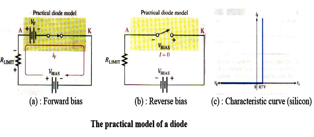
4 Diode Approximations 2. The Barrier Potential Model The forward biased diode is represented as a closed switch in series with a small battery equal to the barrier potential VB (0.7 V for Si and 0.3 V for Ge) The positive end of the equivalent battery is toward the anode. This barrier potential cannot be measured by using a multimeter, but it has the effect of a battery when forward bias is applied. The reverse biased diode is represented by an open switch, because barrier potential does not affect reverse bias.
5 Diode Approximations

6 Diode Approximations 3. The Complete Diode Model The forward biased diode model with both the barrier potential and low forward (bulk) resistance ( r d )
7 HALF-WAVE RECTIFIER CIRCUITS The basic rectifier circuit converts an ac voltage to a pulsating dc voltage. A filter is then added to eliminate the ac components of the waveform and produce a nearly constant dc voltage output.
8 HALF-WAVE RECTIFIER WITH RESISTOR LOAD The simplest single-phase diode rectifier is the single-phase half-wave rectifier. The circuit consists of only one diode that is usually fed with a transformer secondary. During the positive half-cycle of the transformer secondary voltage, diode conducts. During the negative half-cycle, diode stops conducting.
9 HALF-WAVE RECTIFIER WITH RESISTOR LOAD
10 HALF-WAVE RECTIFIER WITH RESISTOR LOAD The average value of output voltage V dc is defined as: V p Vdc 0.318V The average current I dc is : I The root-mean-square (rms) value of output voltage v o is V o, which is defined as: V p V o V V o p And 2 The rectification efficiency is I o R 2R p dc V R dc V P R 2 I R dc dc 2 in o d P P I r R
11 HALF-WAVE RECTIFIER WITH RESISTOR LOAD By Substituting and simplifying, we get on: If diode resistance r d is neglected, then 0.46 r R 1 d 0.46 or 46% PIV It is the maximum voltage across the diode in the reverse direction. PIV for diode in half wave rectifier is V p
12 HALF-WAVE RECTIFIER WITH RESISTOR LOAD 1- For this case, the output voltage is one diode-drop smaller than the input voltage during the conduction interval: 2- The output voltage remains zero during the off-state interval. The input and output waveforms for the half-wave rectifier, including the effect of Von, are shown in the figure for V P = 10 V and V on = 0.7V. Half-wave rectifier output voltage with V P = 10 V and V on = 0.7 V.
13 RECTIFIER with FILTER CAPACITOR The unfiltered output of the half-wave rectifier is not suitable for operation of most electronic circuits because constant power supply voltages are required to establish proper bias for the electronic devices. A filter capacitor can be added to filter the output of the rectifier circuit to remove the time-varying components from the waveform.
14 RECTIFIER with FILTER CAPACITOR A load must be connected to the circuit as represented by the resistor R. Now there is a path available to discharge the capacitor during the time the diode is not conducting.
15 RECTIFIER with FILTER CAPACITOR The output voltage is no longer constant as in the ideal peakdetector circuit but has a ripple voltage V r. In addition, the diode only conducts for a short timet during each cycle. This time DT is called the conduction interval, and its angular equivalent is the conduction angle q C where q C = ωt. the ripple voltage: The conduction angle and conduction interval are: The PIV of diode with capacitor filter is:
16 Half-wave diode rectifier Example: Find the value of the dc output voltage, dc output current, ripple voltage, conduction interval, and conduction angle for a half-wave rectifier driven from a transformer having a secondary voltage of 12.6 V rms (60 Hz) with R = 15W and C = 25,000mF. Assume the diode on-voltage V on = 1 V. Solution The ideal dc output voltage in the absence of ripple is The nominal dc current delivered by the supply is
17 The ripple voltage is Half-wave diode rectifier The conduction angle is and the conduction interval is
18 Home work H.W4: Find the value of the dc output voltage, dc output current, ripple voltage, conduction interval, and conduction angle for a half-wave rectifier that is being supplied from a transformer having a secondary voltage of 6.3 V rms (60 Hz) with R = 0.5W and C = 500,000mF. Assume the diode on voltage V on = 1 V. Answers: 7.91 V; 15.8 A; 0.527; ms; 19.7
Lecture (04) PN Diode applications II
 PN Diode applications II") Lecture (04) PN Diode applications II By: Dr. Ahmed ElShafee ١ Agenda Full wave rectifier, cont.,.. Filters Voltage Regulators ٢ RMS The RMS value of a set of values (or a continuous time waveform) is
Lecture (04) PN Diode applications II By: Dr. Ahmed ElShafee ١ Agenda Full wave rectifier, cont.,.. Filters Voltage Regulators ٢ RMS The RMS value of a set of values (or a continuous time waveform) is
Diodes & Rectifiers Nafees Ahamad
 Diodes & Rectifiers Nafees Ahamad Asstt. Prof., EECE Deptt, DIT University, Dehradun Website: www.eedofdit.weebly.com 1 Diodes Electronic devices created by bringing together a p-type and n-type region
Lecture (03) Diodes and Diode Applications I
 Diodes and Diode Applications I") Lecture (03) Diodes and Diode Applications I By: Dr. Ahmed ElShafee ١ Agenda VOLTAGE CURRENT CHARACTERISTIC OF A DIODE Forward bias Reverse Bias V I Characteristic for Forward Bias V I Characteristic for
Lecture (03) Diodes and Diode Applications I By: Dr. Ahmed ElShafee ١ Agenda VOLTAGE CURRENT CHARACTERISTIC OF A DIODE Forward bias Reverse Bias V I Characteristic for Forward Bias V I Characteristic for
Lecture (03) Diode applications
 Diode applications") Lecture (03) Diode applications By: Dr. Ahmed ElShafee ١ Agenda The Basic DC Power Supply Half wave rectifier Full wave rectifier Filters Voltage Regulators ٢ The Basic DC Power Supply All active electronic
Lecture (03) Diode applications By: Dr. Ahmed ElShafee ١ Agenda The Basic DC Power Supply Half wave rectifier Full wave rectifier Filters Voltage Regulators ٢ The Basic DC Power Supply All active electronic
3. Diode, Rectifiers, and Power Supplies
 3. Diode, Rectifiers, and Power Supplies Semiconductor diodes are active devices which are extremely important for various electrical and electronic circuits. Diodes are active non-linear circuit elements
Lecture (04) Diode applications, cont.
 Diode applications, cont.") Lecture (04) Diode applications, cont. By: Dr. Ahmed ElShafee Agenda Full wave rectifier, cont.,.. Filters Voltage Regulators Diode limiters Diode Clampers ١ ٢ Bridge Full Wave Rectifier Operation uses
Lecture (04) Diode applications, cont. By: Dr. Ahmed ElShafee Agenda Full wave rectifier, cont.,.. Filters Voltage Regulators Diode limiters Diode Clampers ١ ٢ Bridge Full Wave Rectifier Operation uses
Circuit operation Let s look at the operation of this single diode rectifier when connected across an alternating voltage source v s.
 Diode Rectifier Circuits One of the important applications of a semiconductor diode is in rectification of AC signals to DC. Diodes are very commonly used for obtaining DC voltage supplies from the readily
Examples to Power Supply
 Examples to Power Supply Example-1: A center-tapped full-wave rectifier connected to a transformer whose each secondary coil has a r.m.s. voltage of 1 V. Assume the internal resistances of the diode and
CHAPTER 1 DIODE CIRCUITS. Semiconductor act differently to DC and AC currents
 CHAPTER 1 DIODE CIRCUITS Resistance levels Semiconductor act differently to DC and AC currents There are three types of resistances 1. DC or static resistance The application of DC voltage to a circuit
Electronic Devices. Floyd. Chapter 2. Ninth Edition. Electronic Devices, 9th edition Thomas L. Floyd
 Electronic Devices Ninth Edition Floyd Chapter 2 Agenda Diode Circuits and Applications Half-wave Rectifier Full-wave Rectifier Power Supply Filter Power Supply Regulator Diode Limiting Circuits Diode
2) The larger the ripple voltage, the better the filter. 2) 3) Clamping circuits use capacitors and diodes to add a dc level to a waveform.
 The larger the ripple voltage, the better the filter. 2) 3) Clamping circuits use capacitors and diodes to add a dc level to a waveform.") TRUE/FALSE. Write 'T' if the statement is true and 'F' if the statement is false. 1) A diode conducts current when forward-biased and blocks current when reverse-biased. 1) 2) The larger the ripple voltage,
TRUE/FALSE. Write 'T' if the statement is true and 'F' if the statement is false. 1) A diode conducts current when forward-biased and blocks current when reverse-biased. 1) 2) The larger the ripple voltage,
Experiment #2 Half Wave Rectifier
 PURPOSE: ELECTRONICS 224 ETR620S Experiment #2 Half Wave Rectifier This laboratory session acquaints you with the operation of a diode power supply. You will study the operation of half-wave and the effect
Basic Electronic Devices and Circuits EE 111 Electrical Engineering Majmaah University 2 nd Semester 1432/1433 H. Chapter 2. Diodes and Applications
 Basic Electronic Devices and Circuits EE 111 Electrical Engineering Majmaah University 2 nd Semester 1432/1433 H Chapter 2 Diodes and Applications 1 Diodes A diode is a semiconductor device with a single
Exercise 3: EXERCISE OBJECTIVE
 Exercise 3: EXERCISE OBJECTIVE voltage equal to double the peak ac input voltage by using a voltage doubler circuit. You will verify your results with a multimeter and an oscilloscope. DISCUSSION times
DEPARTMENT OF ELECTRICAL ENGINEERING LAB WORK EE301 ELECTRONIC CIRCUITS
 DEPARTMENT OF ELECTRICAL ENGINEERING LAB WORK EE301 ELECTRONIC CIRCUITS EXPERIMENT : 1 TITLE : Half-Wave Rectifier & Filter OUTCOME : Upon completion of this unit, the student should be able to: i. Construct
Chapter 2. Diodes & Applications
 Chapter 2 Diodes & Applications The Diode A diode is made from a small piece of semiconductor material, usually silicon, in which half is doped as a p region and half is doped as an n region with a pn
Electronic Circuits I - Tutorial 03 Diode Applications I
 Electronic Circuits I - Tutorial 03 Diode Applications I -1 / 13 - T & F # Question 1 A diode can conduct current in two directions with equal ease. F 2 When reverse-biased, a diode ideally appears as
Electronic Circuits I Laboratory 03 Rectifiers
 Electronic Circuits I Laboratory 03 Rectifiers # Student ID Student Name Grade (10) 1 Instructor signature 2 3 4 5 Delivery Date -1 / 18 - Objectives In this experiment, you will get to know a group of
CHAPTER 5: REGULATED DC POWER SUPPLY
 CHAPTER 5: REGULATED DC POWER SUPPLY Dr. Wan Mahani Hafizah binti Wan Mahmud Topics in Chapter 5 5.0Introduction 5.1Rectifier 5.2Filter 5.3oltage Regulator 5.4Switching Regulator 2 Power Supply Block Diagram
After performing this experiment, you should be able to:
 Objectives: After performing this experiment, you should be able to: Demonstrate the strengths and weaknesses of the two basic rectifier circuits. Draw the output waveforms for the two basic rectifier
1 Diodes. 1.1 Diode Models Ideal Diode. ELEN 236 Diodes
 ELEN 236 Diodes 1 Diodes 1.1 Diode Models 1.1.1 Ideal Diode Current through diode is zero for any voltage less than zero i.e. reverse biased case Current through diode is not limited by diode if voltage
Başkent University Department of Electrical and Electronics Engineering EEM 214 Electronics I Experiment 2. Diode Rectifier Circuits
 Başkent University Department of Electrical and Electronics Engineering EEM 214 Electronics I Experiment 2 Diode Rectifier Circuits Aim: The purpose of this experiment is to become familiar with the use
Linear DC Power Supply Parts 1
 Linear DC Power Supply Parts 1 Engr. Muhammad Muizz Bin Mohd Nawawi JABATAN KEJURUTERAAN ELEKTRIK POLITEKNIK KOTA KINABALU VER JUN2011 A presentation of esyst.org Power Supply All electronic circuits need
Lec (03) Diodes and Applications
 Diodes and Applications") Lec (03) Diodes and Applications Diode Models 1 Diodes and Applications Diode Operation V-I Characteristics of a Diode Diode Models Half-Wave and Full-Wave Rectifiers Power Supply Filters and Regulators
Lec (03) Diodes and Applications Diode Models 1 Diodes and Applications Diode Operation V-I Characteristics of a Diode Diode Models Half-Wave and Full-Wave Rectifiers Power Supply Filters and Regulators
3.4. Operation in the Reverse Breakdown
 3.4. peration in the Reverse Breakdown Under certain circumstances, diodes may be intentionally used in the reverse breakdown region These are referred to as Zener Diode or Breakdown Diode Voltage regulator
Lecture 7: Diode Rectifier Circuits (Half Cycle, Full Cycle, and Bridge).
.") Whites, EE 320 Lecture 7 Page 1 of 9 Lecture 7: Diode Rectifier Circuits (Half Cycle, Full Cycle, and Bridge). We saw in the previous lecture that Zener diodes can be used in circuits that provide (1)
Whites, EE 320 Lecture 7 Page 1 of 9 Lecture 7: Diode Rectifier Circuits (Half Cycle, Full Cycle, and Bridge). We saw in the previous lecture that Zener diodes can be used in circuits that provide (1)
UNIVERSITY OF NORTH CAROLINA AT CHARLOTTE. Department of Electrical and Computer Engineering
 UNIVERSITY OF NORTH CAROLINA AT CHARLOTTE Department of Electrical and Computer Engineering Experiment No. 2 - Semiconductor Diodes Overview: In this lab session students will investigate I-V characteristics
Experiment No.5 Single-Phase half wave Voltage Multiplier
 Experiment No.5 Single-Phase half wave Voltage Multiplier Experiment aim The aim of this experiment is to design and analysis of a single phase voltage multiplier. Apparatus Make the circuit for voltage
EXPERIMENT 5 : THE DIODE
 EXPERIMENT 5 : THE DIODE Equipment List Dual Channel Oscilloscope R, 330, 1k, 10k resistors P, Tri-Power Supply V, 2x Multimeters D, 4x 1N4004: I max = 1A, PIV = 400V Silicon Diode P 2 35.6V pp (12.6 V
Sheet 2 Diodes. ECE335: Electronic Engineering Fall Ain Shams University Faculty of Engineering. Problem (1) Draw the
 Draw the") Ain Shams University Faculty of Engineering ECE335: Electronic Engineering Fall 2014 Sheet 2 Diodes Problem (1) Draw the i) Charge density distribution, ii) Electric field distribution iii) Potential distribution,
Ain Shams University Faculty of Engineering ECE335: Electronic Engineering Fall 2014 Sheet 2 Diodes Problem (1) Draw the i) Charge density distribution, ii) Electric field distribution iii) Potential distribution,
Electronic Circuits. Diode Applications. Dr. Manar Mohaisen Office: F208 Department of EECE
 Electronic Circuits Diode Applications Dr. Manar Mohaisen Office: F208 Email: manar.subhi@kut.ac.kr Department of EECE Review of the Precedent Lecture Doping It is a controlled addition of impurities to
Sirindhorn International Institute of Technology Thammasat University at Rangsit
 Sirindhorn International Institute of Technology Thammasat University at Rangsit School of Information, Computer and Communication Technology COURSE : ECS 204 Basic Electrical Engineering Lab INSTRUCTOR
Lecture 3 Diodes & Applications :Outline
 Lecture 3 Diodes & Applications :Outline Introduction Diode biasing Diode model Testing a diode Diode application: Rectifiers Diode application: Voltage multipliers Diode application: Optoelectronics 1
CHAPTER 2. Diode Applications
 CHAPTER 2 Diode Applications 1 Objectives Explain and analyze the operation of both half and full wave rectifiers Explain and analyze filters and regulators and their characteristics Explain and analyze
EXPERIMENT 3 Half-Wave and Full-Wave Rectification
 Name & Surname: ID: Date: EXPERIMENT 3 Half-Wave and Full-Wave Rectification Objective To calculate, compare, draw, and measure the DC output voltages of half-wave and full-wave rectifier circuits. Tools
RECTIFIERS POWER SUPPLY AND VOLTAGE REGULATION. Rectifier. Basic DC Power Supply. Filter. Regulator
 RECTIFIERS POWER SUPPLY AND OLTAGE REGULATION Prepared by Engr. JP Timola Reference: Electronic Devices by Thomas L. Floyd Because of their ability to conduct current in one direction and block current
Diode Characteristics and Applications
 Diode Characteristics and Applications Topics covered in this presentation: Diode Characteristics Diode Clamp Protecting Against Back-EMF Half-Wave Rectifier The Zener Diode 1 of 18 Diode Characteristics
Applications of Diode
 Applications of Diode Diode Approximation: (Large signal operations): 1. Ideal Diode: When diode is forward biased, resistance offered is zero, When it is reverse biased resistance offered is infinity.
Exercise 1: EXERCISE OBJECTIVE DISCUSSION. a. circuit A. b. circuit B. Festo Didactic P0 75
 Exercise 1: EXERCISE OBJECTIVE DISCUSSION a. circuit A. b. circuit B. Festo Didactic 91564-P0 75 individual diodes are designated D instead of CR, with the diode circle symbol omitted.) The input terminals
Diodes (non-linear devices)
") C H A P T E R 4 Diodes (non-linear devices) Ideal Diode Figure 4.2 The two modes of operation of ideal diodes and the use of an external circuit to limit (a) the forward current and (b) the reverse voltage.
C H A P T E R 4 Diodes (non-linear devices) Ideal Diode Figure 4.2 The two modes of operation of ideal diodes and the use of an external circuit to limit (a) the forward current and (b) the reverse voltage.
An Introduction to Rectifier Circuits
 TRADEMARK OF INNOVATION An Introduction to Rectifier Circuits An important application of the diode is one that takes place in the design of the rectifier circuit. Simply put, this circuit converts alternating
EXPERIMENT 7: DIODE CHARACTERISTICS AND CIRCUITS 10/24/10
 DIODE CHARACTERISTICS AND CIRCUITS EXPERIMENT 7: DIODE CHARACTERISTICS AND CIRCUITS 10/24/10 In this experiment we will measure the I vs V characteristics of Si, Ge, and Zener p-n junction diodes, and
ECE321 Electronics I
 ECE321 Electronics Lecture 2: Basic Circuits with Diodes Payman Zarkesh-Ha Office: ECE Bldg. 230B Office hours: Tuesday 2:00-3:00PM or by appointment E-mail: pzarkesh.unm.edu Slide: 1 Review of Last Lecture
EXPERIMENT 5 : DIODES AND RECTIFICATION
 EXPERIMENT 5 : DIODES AND RECTIFICATION Component List Resistors, one of each o 2 1010W o 1 1k o 1 10k 4 1N4004 (Imax = 1A, PIV = 400V) Diodes Center tap transformer (35.6Vpp, 12.6 VRMS) 100 F Electrolytic
EXPERIMENT 5 : THE DIODE
 EXPERIMENT 5 : THE DIODE Component List Resistors, one of each o 1 10 10W o 1 1k o 1 10k 4 1N4004 (I max = 1A, PIV = 400V) Diodes Center tap transformer (35.6V pp, 12.6 V RMS ) 100 F Electrolytic Capacitor
1. An engineer measures the (step response) rise time of an amplifier as. Estimate the 3-dB bandwidth of the amplifier. (2 points)
 rise time of an amplifier as. Estimate the 3-dB bandwidth of the amplifier. (2 points)") Exam 1 Name: Score /60 Question 1 Short Takes 1 point each unless noted otherwise. 1. An engineer measures the (step response) rise time of an amplifier as. Estimate the 3-dB bandwidth of the amplifier.
Exam 1 Name: Score /60 Question 1 Short Takes 1 point each unless noted otherwise. 1. An engineer measures the (step response) rise time of an amplifier as. Estimate the 3-dB bandwidth of the amplifier.
Power Electronics Single Phase Uncontrolled Half Wave Rectifiers. Dr. Firas Obeidat
 Power Electronics Single Phase Uncontrolled Half Wave Rectifiers Dr. Firas Obeidat 1 Table of contents 1 Resistive Load 2 R-L Load 3 R-L Load with Freewheeling Diode 4 Half Wave Rectifier with a Capacitor
Sirindhorn International Institute of Technology Thammasat University at Rangsit
 Sirindhorn International Institute of Technology Thammasat University at Rangsit School of Information, Computer and Communication Technology COURSE : ECS 204 Basic Electrical Engineering Lab INSTRUCTOR
EE292: Fundamentals of ECE
 EE292: Fundamentals of ECE Fall 2012 TTh 10:00-11:15 SEB 1242 Lecture 12 121004 http://www.ee.unlv.edu/~b1morris/ee292/ 2 Outline Review More Diodes Lab Kits 3 Diode Voltage/Current Characteristics Forward
The Discussion of this exercise covers the following points:
 Exercise 1 Power Diode Single-Phase Rectifiers EXERCISE OBJECTIVE When you have completed this exercise, you will know what a diode is, and how it operates. You will be familiar with two types of circuits
Objective Type Questions 1. Why pure semiconductors are insulators at 0 o K? 2. What is effect of temperature on barrier voltage? 3.
 Objective Type Questions 1. Why pure semiconductors are insulators at 0 o K? 2. What is effect of temperature on barrier voltage? 3. What is difference between electron and hole? 4. Why electrons have
3.4. Reverse Breakdown Region Zener Diodes In the breakdown region Very steep i-v curve Almost constant voltage drop Used for voltage regulator
 3.4. Reverse Breakdown Region Zener Diodes In the breakdown region Very steep i-v curve Almost constant voltage drop Used for voltage regulator Voltage regulator Provide a constant dc output voltage If
Electronics for Analog Signal Processing - I Prof. K. Radhakrishna Rao Department of Electrical Engineering Indian Institute of Technology - Madras
 Electronics for Analog Signal Processing - I Prof. K. Radhakrishna Rao Department of Electrical Engineering Indian Institute of Technology - Madras Lecture - 6 Full Wave Rectifier and Peak Detector In
Electronics 1 Lab (CME 2410)
") Electronics 1 Lab (CME 410) School of Informatics & Computing German Jordanian University Laboratory Experiment () 1. Objective: Half-Wave, Full-Wave Rectifiers o be familiar with the half-wave rectifier,
Electronics 1 Lab (CME 410) School of Informatics & Computing German Jordanian University Laboratory Experiment () 1. Objective: Half-Wave, Full-Wave Rectifiers o be familiar with the half-wave rectifier,
Lecture 2 p-n junction Diode characteristics. By Asst. Prof Dr. Jassim K. Hmood
 Electronic I Lecture 2 p-n junction Diode characteristics By Asst. Prof Dr. Jassim K. Hmood THE p-n JUNCTION DIODE The pn junction diode is formed by fabrication of a p-type semiconductor region in intimate
EE 105. Diode Circuits. Prof. Ali M. Niknejad and Prof. Rikky Muller. March 2, U.C. Berkeley Copyright 2017 by Ali M.
 EE 105 Diode Circuits Prof. Ali M. Niknejad and Prof. Rikky Muller U.C. Berkeley Copyright 2017 by Ali M. Niknejad March 2, 2017 1/ 23 Diode Introduction A diode is a non-linear element. To a very good
EXPERIMENT 5 : THE DIODE
 EXPERIMENT 5 : THE DIODE Component List Resistors, one of each o 1 10 10W o 1 1k o 1 10k 4 1N4004 (Imax = 1A, PIV = 400V) Diodes Center tap transformer (35.6Vpp, 12.6 VRMS) 100 F Electrolytic Capacitor
LECTURE.3 : AC-DC CONVERSION
 LECTURE.3 : AC-DC CONVERSION (RECTIFICATIONS) 3.1Basic Rectifier Circuits Several types of rectifier circuits are available: single-phase and three-phase half-wave and full-wave, controlled and uncontrolled,
AC Theory and Electronics
 AC Theory and Electronics An Alternating Current (AC) or Voltage is one whose amplitude is not constant, but varies with time about some mean position (value). Some examples of AC variation are shown below:
IENGINEERS- CONSULTANTS QUESTION BANK SERIES ELECTRONICS ENGINEERING 1 YEAR UPTU
 ELECTRONICS ENGINEERING Unit 1 Objectives Q.1 The breakdown mechanism in a lightly doped p-n junction under reverse biased condition is called. (A) avalanche breakdown. (B) zener breakdown. (C) breakdown
LABORATORY MODULE. Analog Electronics. Semester 2 (2005/2006)
") LABORATORY MODULE ENT 162 Analog Electronics Semester 2 (2005/2006) EXPERIMENT 1 : Introduction to Diode Name Matric No. : : PUSAT PENGAJIAN KEJURUTERAAN MEKATRONIK KOLEJ UNIVERSITI KEJURUTERAAN UTARA
LABORATORY MODULE ENT 162 Analog Electronics Semester 2 (2005/2006) EXPERIMENT 1 : Introduction to Diode Name Matric No. : : PUSAT PENGAJIAN KEJURUTERAAN MEKATRONIK KOLEJ UNIVERSITI KEJURUTERAAN UTARA
Diodes and Applications
 Diodes and Applications Diodes and Applications 2 1 Diode Operation 2 2 Voltage-Current (V-I) Characteristics 2 3 Diode Models 2 4 Half-Wave Rectifiers 2 5 Full-Wave Rectifiers 2 6 Power Supply Filters
A.C voltmeters using rectifier
 Lecture 5 A.C voltmeters using rectifier The PMMC movement used in d.c. voltmeters can be effectively used in a.c. voltmeters. The rectifier is used to convert a.c. voltage to be measured, to d.c. This
Exercise 12. Semiconductors EXERCISE OBJECTIVE DISCUSSION OUTLINE DISCUSSION. Introduction to semiconductors. The diode
 Exercise 12 Semiconductors EXERCISE OBJECTIVE When you have completed this exercise, you will be familiar with the operation of a diode. You will learn how to use a diode to rectify ac voltage to produce
ECE321 Electronics I
 ECE32 Electronics Lecture 2: Basic Circuits with iodes Payman Zarkesh-Ha Office: ECE Bldg. 230B Office hours: Tuesday 2:00-3:00PM or by appointment E-mail: payman@ece.unm.edu Slide: Review of Last Lecture
Power Supplies and Circuits. Bill Sheets K2MQJ Rudolf F. Graf KA2CWL
 Power Supplies and Circuits Bill Sheets K2MQJ Rudolf F. Graf KA2CWL The power supply is an often neglected important item for any electronics experimenter. No one seems to get very excited about mundane
ELEN-325. Introduction to Electronic Circuits: Design Approach. ELEN-325. Part IV. Diode s Applications
 Jose SilvaMartinez ELEN325. Part I. Diode s Applications 1. The PN junction (diode). The diode is a unidirectional device with two modes of operation: Forward bias when current can flow through the device
RECTIFIERS AND POWER SUPPLIES
 UNIT V RECTIFIERS AND POWER SUPPLIES Half-wave, full-wave and bridge rectifiers with resistive load. Analysis for Vdc and ripple voltage with C,CL, L-C and C-L-C filters. Voltage multipliers Zenerdiode
(A) im (B) im (C)0.5 im (D) im.
 im (B) im (C)0.5 im (D) im.") Dr. Mahalingam College of Engineering and Technology, Pollachi. (An Autonomous Institution affiliated to Anna University) Regulation 2014 Fourth Semester Electrical and Electronics Engineering 141EE0404
Dr. Mahalingam College of Engineering and Technology, Pollachi. (An Autonomous Institution affiliated to Anna University) Regulation 2014 Fourth Semester Electrical and Electronics Engineering 141EE0404
Federal Urdu University of Arts, Science & Technology Islamabad Pakistan SECOND SEMESTER ELECTRONICS - I
 SECOND SEMESTER ELECTRONICS - I BASIC ELECTRICAL & ELECTRONICS LAB DEPARTMENT OF ELECTRICAL ENGINEERING Prepared By: Checked By: Approved By: Engr. Yousaf Hameed Engr. M.Nasim Khan Dr.Noman Jafri Lecturer
VTU NOTES QUESTION PAPERS NEWS RESULTS FORUMS TESTING OF HALF WAVE, FULL WAVE AND BRIDGE RECTIFIERS WITH AND WITHOUT CAPACITOR
 TESTING OF HALF WAVE, FULL WAVE AND BRIDGE RECTIFIERS WITH AND WITHOUT CAPACITOR Aim: To determine the ripple factor, efficiency and regulation of the half wave, full wave and bridge rectifier circuits
Diode Applications 1
 Diode Applications 1 Explain and analyze the operation of both half and full wave rectifiers Explain and analyze filters and regulators and their characteristics Explain and analyze the operation of diode
Introduction to Rectifiers and their Performance Parameters
 Electrical Engineering Division Page 1 of 10 Rectification is the process of conversion of alternating input voltage to direct output voltage. Rectifier is a circuit that convert AC voltage to a DC voltage
2 MARKS EE2203 ELECTRONIC DEVICES AND CIRCUITS UNIT 1
 2 MARKS EE2203 ELECTRONIC DEVICES AND CIRCUITS UNIT 1 1. Define PN junction. When a p type semiconductor is joined to a N type semiconductor the contact surface is called PN junction. 2. What is an ideal
Prof. Anyes Taffard. Physics 120/220. Diode Transistor
 Prof. Anyes Taffard Physics 120/220 Diode Transistor Diode One can think of a diode as a device which allows current to flow in only one direction. Anode I F Cathode stripe Diode conducts current in this
Zener Diodes. Specifying and modeling the zener diode. - Diodes operating in the breakdown region can be used in the design of voltage regulators.
 Zener Diodes - Diodes operating in the breakdown region can be used in the design of voltage regulators. Specifying and modeling the zener diode Dynamic resistance, r Z a few ohms to a few tens of ohms
Questions from the same exercise can be combined together to increase difficulty. Which one of the following properties of the diode is NOT true:
 Questions from the same exercise can be combined together to increase difficulty. 21 1 Which one of the following properties of the diode is NOT true: a) When no voltage is applied across the diode, it
SUMMER 13 EXAMINATION Subject Code: Model Answer Page No: / N
 Important Instructions to examiners: 1) The answers should be examined by key words and not as word-to-word as given in the model answer scheme. 2) The model answer and the answer written by candidate
Dr.Arkan A.Hussein Power Electronics Fourth Class. 3-Phase Voltage Source Inverter With Square Wave Output
 3-Phase Voltage Source Inverter With Square Wave Output ١ fter completion of this lesson the reader will be able to: (i) (ii) (iii) (iv) Explain the operating principle of a three-phase square wave inverter.
Analog Electronic Circuits
 Analog Electronic Circuits Chapter 1: Semiconductor Diodes Objectives: To become familiar with the working principles of semiconductor diode To become familiar with the design and analysis of diode circuits
Unregulated Power Supply Tutorial
 Unregulated Power Supply Tutorial Unregulated Power Supply Tutorial: Hey! Why is my 9V wall-wart outputting 14V?! There are a few possible reasons for this. We've also written this tutorial to show you
POWER SUPPLY MODEL XP-720. Instruction Manual ELENCO
 POWER SUPPLY MODEL XP-720 Instruction Manual ELENCO Copyright 2016, 1997 by ELENCO Electronics, Inc. All rights reserved. Revised 2016 REV-H 753270 No part of this book shall be reproduced by any means;
Power Supplies. Linear Regulated Supplies Switched Regulated Supplies Batteries
 Power Supplies Linear Regulated Supplies Switched Regulated Supplies Batteries Im Alternating Current The Power -Im π/2 π 2π π t Im Idc Direct Current Supply π/2 π 2 π πt -Im ٢ http://bkaragoz.kau.edu.sa
EE 110 Introduction to Engineering & Laboratory Experience Saeid Rahimi, Ph.D. Lab 6 Diodes: Half-Wave and Full-Wave Rectifiers Converting AC to DC
 EE 110 Introduction to Engineering & Laboratory Experience Saeid Rahimi, Ph.D. Lab 6 Diodes: Half-Wave and Full-Wave Rectifiers Converting C to DC The process of converting a sinusoidal C voltage to a
Electronics for Analog Signal Processing - I Prof. K. Radhakrishna Rao Department of Electrical Engineering Indian Institute of Technology - Madras
 Electronics for Analog Signal Processing - I Prof. K. Radhakrishna Rao Department of Electrical Engineering Indian Institute of Technology - Madras Lecture - 4 Rectifier We have had a discussion about
Shankersinh Vaghela Bapu Institute of Technology INDEX
 Shankersinh Vaghela Bapu Institute of Technology Diploma EE Semester III 3330905: ELECTRONIC COMPONENTS AND CIRCUITS INDEX Sr. No. Title Page Date Sign Grade 1 Obtain I-V characteristic of Diode. 2 To
EE 105. Diode Circuits. Prof. Ali M. Niknejad and Prof. Rikky Muller. U.C. Berkeley Copyright c 2017 by Ali M. Niknejad
 EE 105 Diode Circuits Prof. Ali M. Niknejad and Prof. Rikky Muller U.C. Berkeley Copyright c 2017 by Ali M. Niknejad March 2, 2017 1 / 23 Diode Introduction A diode is a non-linear element. To a very good
Single-Phase Half-Wave Rectifiers
 ectifiers Single-Phase Half-Wave ectifiers A rectifier is a circuit that converts an ac signal into a unidirectional signal. A single-phase half-way rectifier is the simplest type. Although it is not widely
Mechatronics Chapter 3-1 Semiconductor devices Diode
 MEMS1082 Mechatronics Chapter 3-1 Semiconductor devices Diode Semiconductor: Si Semiconductor N-type and P-type Semiconductors There are two types of impurities: N-type - In N-type doping, phosphorus or
ECEN5817 Lecture 4. Transfer function H(s) ) (t) i R. (t) v R
 ) (t) i R. (t) v R") ECEN5817 Lecture 4 A resonant dc-dc converter: Transfer function H(s) ) dc source v g i s L C s i R i v s v R v R N S N T N R N F Switch network Resonant tank network Rectifier network Low-pass dc filter
ECEN5817 Lecture 4 A resonant dc-dc converter: Transfer function H(s) ) dc source v g i s L C s i R i v s v R v R N S N T N R N F Switch network Resonant tank network Rectifier network Low-pass dc filter
Code No: R Set No. 1
 Code No: R05010204 Set No. 1 I B.Tech Supplimentary Examinations, Aug/Sep 2007 ELECTRONIC DEVICES AND CIRCUITS ( Common to Electrical & Electronic Engineering, Electronics & Communication Engineering,
v o v an i L v bn V d Load L v cn D 1 D 3 D 5 i a i b i c D 4 D 6 D 2 Lecture 7 - Uncontrolled Rectifier Circuits III
 Lecture 7 - Uncontrolled Rectifier Circuits III Three-phase bridge rectifier (p = 6) v o n v an v bn v cn i a i b i c D 1 D 3 D 5 D 4 D 6 D d i L R Load L Figure 7.1 Three-phase diode bridge rectifier
 FINALTERM EXAMINATION Fall 2009 PHY301- Circuit Theory (Session - 2) Time: 120 min Marks: 70 Question No: 1 ( Marks: 1 ) - Please choose one Charge of 2c and 5c will attract each other repel each other
Basic Electronics Important questions
 Basic Electronics Important questions B.E-2/4 Mech- B Faculty: P.Lakshmi Prasanna Note: Read the questions in the following order i. Assignment questions ii. Class test iii. Expected questions iv. Tutorials
SIMULATION DESIGN TOOL LABORATORY MANUAL
 SHANKERSINH VAGHELA BAPU INSTITUTE OF TECHNOLOGY SIMULATION DESIGN TOOL LABORATORY MANUAL B.E. 4 th SEMESTER-2015-16 SHANKERSINH VAGHELA BAPU INSTITUTE OF TECHNOLOGY Gandhinagar-Mansa Road, PO. Vasan,
EE 462: Laboratory # 4 DC Power Supply Circuits Using Diodes
 EE 462: Laboratory # 4 DC Power Supply Circuits Using Diodes by Dr. A.V. Radun Dr. K.D. Donohue (9/18/03) Department of Electrical and Computer Engineering University of Kentucky Lexington, KY 40506 Laboratory
ECE 1750 Week ( part (part 1) Rectifiers
 Rectifiers") ECE 1750 Week 3 (part 1) Rectifiers 1 Rectifier Rectifiers convert ac into dc Some commercial rectifiers: (Used to charge batteries like those on the right) Example of Assumed State Analysis V ac R L Consider
ECE 1750 Week 3 (part 1) Rectifiers 1 Rectifier Rectifiers convert ac into dc Some commercial rectifiers: (Used to charge batteries like those on the right) Example of Assumed State Analysis V ac R L Consider
Table of Contents. iii
 Table of Contents Subject Page Experiment 1: Diode Characteristics... 1 Experiment 2: Rectifier Circuits... 7 Experiment 3: Clipping and Clamping Circuits 17 Experiment 4: The Zener Diode 25 Experiment
Electro - Principles I
 Page 12-1 The Basic Power Supply The Power Supply The power supply is used to convert the AC energy provided by the wall outlet to dc energy. In most electronic equipment, the power cord supplies the ac
Part I Lectures 1-7 Diode Circuit Applications
 Part Lectures -7 iode Circuit Applications The PN Junction iode Electrical and Electronic Engineering epartment Lecture One - Page of 7 Second Year, Electronics, 9 - The PN Junction iode Basic Construction: