Online Assessment of Capacitor Banks Using Circuit Health Monitoring Technology
|
|
|
- Christian Gilbert
- 6 years ago
- Views:
Transcription
1 Online Assessment of Capacitor Banks Using Circuit Health Monitoring Technology Jeffrey Wischkaemper (Presenter) B. Don Russell Carl L. Benner Karthick Muthu Manivannan Texas A&M University College Station, Texas Grid of the Future Symposium CIGRE US National Committee 21 October 2014 Houston, Texas, USA CWG/9416P Page 1
2 Copyright 2014, The Texas A&M University System 2 Electrical Feeder Operational Paradigms Traditional Thinking Time Normal Operation Broken Major Event - Outage - Line Down - Fire Reality Normal Operation Broken Pre-Failure Period (hours, days, weeks) Detecting pre-failures makes it possible to make repairs before major events occur.

 but do not record data of sufficient fidelity to support DFA functions.")
, enabling oversight of those devices, without requiring communications to them.")
3 Copyright 2014, The Texas A&M University System 3 Fundamental Principles of Waveform Analytics Feeder-level electrical waveforms represent feeder activity. Sophisticated waveform analytics, applied to waveforms of sufficient fidelity, can detect failures, pre-failures, and other feeder events. PQ meters and relays have the same inputs (i.e., CTs and PTs) but do not record data of sufficient fidelity to support DFA functions. Waveform analytics also report operations of line devices (reclosers, capacitors, etc.), enabling oversight of those devices, without requiring communications to them. With support from EPRI and others, Texas A&M has developed an online system of waveform analytics. This system, known as DFA Technology, provides situational intelligence that enables improvements in reliability, operational efficiency, and safety.


4 4 Measured Example Graph shows current during normal feeder operations. Analytics report this specifically as a failing clamp. Failing clamps can degrade service quality and, in extreme cases, burn down lines. Conventional technologies do not detect pre-failures such as this one. On-Line Waveform Analytics
5 Copyright 2014, The Texas A&M University System 5 Monitoring Topology Failing Apparatus Substation Transformer High-fidelity DFA devices, connected to conventional CTs and PTs, one per feeder.
6 6 Documented Failures Voltage regulator failure LTC controller maloperation Repetitive overcurrent faults Lightning arrestor failures Switch and clamp failures Cable failures Main substation cable URD primary cables URD secondary cables Overhead secondary cables Tree/vegetation contacts Contacts with primary Contacts with secondary services Pole-top xfmr bushing failure Pole-top xfmr winding failure URD pad mount xfmr failure Bus capacitor bushing failure Capacitor problems Controller maloperation Failed capacitor cans Blown fuses Switch restrike Switch sticking Switch burn-ups Switch bounce Pack failure Certain failure types have been seen many times and are well understood. Others have been seen fewer times. DFA system architecture anticipates and accommodates updates to analytics as new events are encountered, analyzed, and documented.


7 7 CenterPoint Energy Project Began DFA trial in 2012 Instrumented four feeders Two 12.5 kv feeders Two 34.5 kv feeders Has detected multiple events Repetitive tree-induced conductor clash that severely damaged conductors Failing line switch Capacitor restrikes Pre-failure of capacitor vacuum switch (to be detailed in today s presentation) Note: This is a partial list
8 Copyright 2014, The Texas A&M University System 8 Detailed Use Case Capacitor Vacuum Switch Pre-Failure CenterPoint uses one-way paging to switch feeder capacitors. After each page, the system monitors substation VARs to verify 1) that the bank has switched and 2) that it is balanced. On 11/29/2013, a DFA device began detecting unusual transients suggesting pre-failure of a capacitor bank. Trouble tickets indicated no problem. CenterPoint and Texas A&M continued to monitor. The transient occurred 500 times over the next 2-1/2 months. After 2-1/2 months, increasing event activity suggested the problem might be accelerating toward failure, prompting corrective action.
9 Copyright 2014, The Texas A&M University System 9 Detailed Use Case Capacitor Vacuum Switch Pre-Failure (cont d) Theory and Analysis Normal capacitor switching causes two phenomena. A short-lived high-frequency transient A step change in voltage (yes, even at the bus!) Each subject event caused a transient, but no step change. This indicates the events were not during switching. Each event caused a high-frequency spike in current and voltage. The current and voltage spikes had the same polarity (i.e., when voltage spiked up, current spiked up). This indicated a reverse event. For forward events, voltage and current spikes have opposing polarities. From the DFA s perspective, a reverse event is one occurring on a different feeder or on the bus itself. Ten Seconds of RMS Bus Voltages (no steady-state change) Bus Voltage and Feeder Current
10 Copyright 2014, The Texas A&M University System 10 Detailed Use Case Capacitor Vacuum Switch Pre-Failure (cont d) Statistical Analysis #1: Number of transient events recorded per day, during 75-day period. Graph shows the number of events on each day (11/29/2013 2/12/2014) There is no definitive trend. Peaks weakly suggest a slight increase in activity over time.
11 Copyright 2014, The Texas A&M University System 11 Detailed Use Case Capacitor Vacuum Switch Pre-Failure (cont d) Statistical Analysis #2: Number of transient events recorded as a function of time of day. Graph shows the frequency of events as a function of time of day, cumulatively for the 75-day period. Events occur at all times of day but most frequently during the middle of the day. 64% occur during 25% of day. (319 of 502 events between 10:00 and 16:00) 47% occur during 17% of day. (238 of 502 events between 11:00 and 15:00)
12 Copyright 2014, The Texas A&M University System 12 Detailed Use Case Capacitor Vacuum Switch Pre-Failure (cont d) On February 14, the utility decided to open the fuses of all five of the feeder s banks to confirm the pre-failure capacitor bank diagnosis. A crew found an anomaly at the first bank. The bank s closed current should be 30 amps. The paging system showed the bank as open. A hot-stick meter showed 0.7 amps through the open switch. First bank s fuses were pulled. Other four banks were left in service. DFA system was watched for five days. Absence of additional transients validated diagnosis. The pre-failure switch failed a hi-pot test. A vacuum interrupter expert performed a root cause analysis. Magnetron- Based Vacuum Tester
 Red/Green Indicator on Normal Phase Red/Green Indicator on")

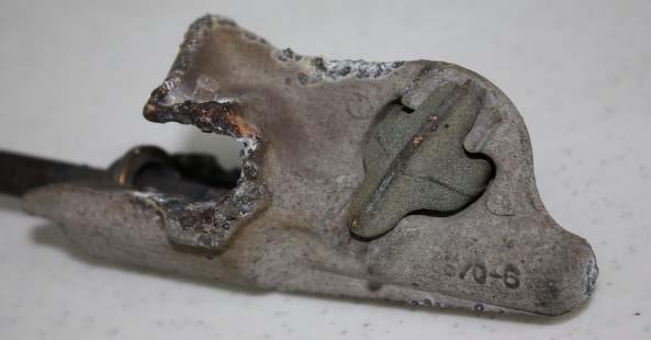
13 Copyright 2014, The Texas A&M University System 13 Detailed Use Case Capacitor Vacuum Switch Pre-Failure (cont d) Red/Green Indicator on Normal Phase Red/Green Indicator on Pre-Failure Phase The switch has a sight window with a red/green position indicator. The pre-failure switch s indicator had clear signs of rubbing against the mechanism housing.
 Normal Indicator Bent Indicator Indicator on")

14 Copyright 2014, The Texas A&M University System 14 Detailed Use Case Capacitor Vacuum Switch Pre-Failure (cont d) Normal Indicator Bent Indicator Indicator on Normal Phase Indicator on Pre-Failure Phase The indicator on the normal phase has an intentional 90-degree bend. The indicator on the pre-failure phase clearly is deformed.


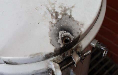
15 Copyright 2014, The Texas A&M University System 15 Detailed Use Case Capacitor Vacuum Switch Pre-Failure (cont d) Red/Green Position Indicator Mechanism on Normal Phase Normal Bent Indicator Rubbing Housing Red/Green Position Indicator Mechanism on Pre-Failure Phase The root cause of the pre-failure was the indicator rubbing and binding, preventing the switch contacts from parting fully. Current (0.7A) flowing through the gap is believed to have caused progressive internal damage to the vacuum interrupter.

16 Copyright 2014, The Texas A&M University System 16 Detailed Use Case Capacitor Vacuum Switch Pre-Failure (cont d) Summary and Conclusions Vacuum switch failures have multiple potential consequences. Least severe: unbalanced capacitor operation Most severe: rupture of switch or capacitor This pre-failure example persisted 2-1/2 months before intervention. Normal operational practices did not and do not detect this kind of pre-failure. Pre-failure detection provided time (in this case, 2-1/2 months) to correct the condition and preempt full failure. Waveform analysis provided only notice and opportunity to correct proactively. Magnetron- Based Vacuum Tester
17 Conclusion Often capacitors can exist in a pre-failure state for an extended period of time (e.g. months) with no conventional notice that there is anything wrong Waveform analytics can detect a wide variety of capacitor problems (switch failures, controller failures, unbalanced operations, etc.). When integrated into utility practice, actionable information provided by waveform analytics allows utilities to prevent catastrophic failures before they occur. CWG/9416P Page 17
")


18 Wildfire Mitigation Through Advanced Monitoring State of Texas Demonstration Project Jeffrey Wischkaemper (Presenter) B. Don Russell Carl L. Benner Karthick Muthu Manivannan Texas A&M University College Station, Texas Grid of the Future Symposium CIGRE US National Committee 21 October 2014 Houston, Texas, USA CWG/9416P Page 18


19 Wildfires A Growing Problem Two of the dozens of bush fires burning out of control in the eastern Australian state of New South Wales were sparked by power lines that had been buffeted by strong winds, fire officials said Saturday, citing preliminary investigations - CNN, 19 October 2013 CWG/9416P Page 19
20 Project Overview In 3-1/2 years, more than 4,000 power line-caused wildfires have occurred in Texas, destroying more than 1,000 square miles (About the size of Rhode Island). (Examples: Bastrop, Steiner Ranch) The Texas A&M Engineering Experiment Station (TEES) and the Texas A&M Forest Service (TFS) have developed technologies that can be used to mitigate wildfire risk. The State of Texas has approved a 2-year project to instrument 100 distribution circuits as a demonstration of the technology. CWG/9416P Page 20


21 Texas Wildfires 2009 mid 2012 CWG/9416P Page 21


22 How Do Power Lines Cause Fires? Downed Conductors Clashing Conductors Vegetation Failing Apparatus CWG/9416P Page 22


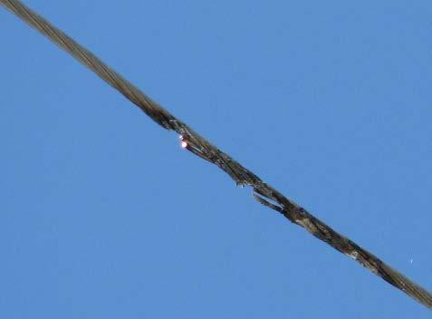
23 Copyright The Texas A&M University System. Example #1: Preventable Failure that Can Cause Fire The pictured limb hung on a phase conductor, sagging it near an underbuilt earth wire. Over the next 24 hours, this caused multiple faults and finally burned the line down. The utility knew nothing of the problem until customers called after the line broke. Each fault represented the potential for ignition. The final fault dropped an energized line and a smoldering limb on the earth. Identify, Find, and Fix Avoid Future Faults, Outages, and Potential Ignition Events The utility asserts that, if they had had DFA technology in operation, they believe they would have prevented multiple fault episodes and the burn-down. 23
24 Copyright The Texas A&M University System. Example #2: Preventable Condition that Can Cause Fire 11/12/2007 Fault 12/02/2007 Same Fault 11/13/2009 Same Fault Identify, Find, and Fix Avoid Future Faults, Outages, and Potential Ignition Events 11/18/2009 Same Fault 12/25/2011 Same Fault Over a period of four years, these five faults all occurred from the same root cause, at the same location, but conventional utility processes did not identify the problem or its root cause. Each episode causes arcing and represents the potential for ignition. Texas A&M s DFA technology determined the root cause, enabling location and repair, to avoid future episodes. 24
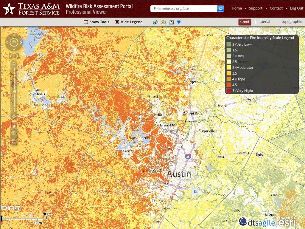
25 Reducing Wildfire Risk: Prevention and Early Notification The project seeks to reduce wildfire risk through two strategies: 1. Prevention TEES developed technology detects equipment pre-failures which may lead to future ignition events 2. Early notification TFS maintains maps which quantify fire risk at locations throughout the state. When TEES detects the occurrence of a powerline event known to be a potential ignition source located in an area with elevated fire risk, automated alerts will be sent to first responders. CWG/9416P Page 25
26 26

27 Power Line-Caused Wildfire Mitigation 27

28 Power Line-Caused Wildfire Mitigation 28


29 Copyright The Texas A&M University System. Project Timeline Utilities will receive monitors for installation in Q All monitors will be installed in Q1 2015, for monitoring throughout the high-risk fire period. Preliminary success stories expected for Grid of the Future 2015 in Chicago! 29
Automated Power System Waveform Analytics for Improved Visibility, Situational Awareness, and Operational Efficiency
 Automated Power System Waveform Analytics for Improved Visibility, Situational Awareness, and Operational Efficiency B. Don Russell (Presenter) Carl L. Benner Jeffrey Wischkaemper Karthick Muthu Manivannan
Application of DFA Technology for Improved Reliability and Operations
 Application of DFA Technology for Improved Reliability and Operations IEEE/IAS Rural Electric Power Conference Columbus, Ohio, 24 April 2017 Robert A. Peterson, P.E., Director Control Center and Emergency
Advanced Monitoring Tools to Improve Distribution System Visibility and Reduce Faults and Outages
 Advanced Monitoring Tools to Improve Distribution System Visibility and Reduce Faults and Outages Presented to the 70th Annual Conference for Protective Relay Engineers Texas A&M University, College Station,
Power Quality Monitoring and Analytics for Transmission and Distribution Systems
 Power Quality Monitoring and Analytics for Transmission and Distribution Systems Doug Dorr Electric Power Research Institute Manager Advanced Monitoring Applications Group PQSynergy 2012 Evolving Smarter
Operational Experience with DFA Technology at Bluebonnet Electric Cooperative and Mid-South Synergy
 Operational Experience with DFA Technology at Bluebonnet Electric Cooperative and Mid-South Synergy Texas Electric Cooperative 35 th Annual Engineering Conference and Exhibit Show Renaissance Austin Hotel
Use of Advanced Monitoring Technology to Detect Incipient Failure of Line Equipment
 Use of Advanced Monitoring Technology to Detect Incipient Failure of Line Equipment 71st Annual Conference for Protective Relay Engineers Texas A&M University College Station, Texas USA 26-29 March 2018
ANALYSIS OF A FLASHOVER OPERATION ON TWO 138KV TRANSMISSION LINES
 ANALYSIS OF A FLASHOVER OPERATION ON TWO 138KV TRANSMISSION LINES Authors: Joe Perez, P.E.: SynchroGrid, College Station, Texas Hung Ming Chou, SynchroGrid, College Station, Texas Mike McMillan, Bryan
Notes 1: Introduction to Distribution Systems
 Notes 1: Introduction to Distribution Systems 1.0 Introduction Power systems are comprised of 3 basic electrical subsystems. Generation subsystem Transmission subsystem Distribution subsystem The subtransmission
Utility System Lightning Protection
 Utility System Lightning Protection Many power quality problems stem from lightning. Not only can the high-voltage impulses damage load equipment, but the temporary fault that follows a lightning strike
PLAN... RESPOND... RESTORE! Utility Automation & Information Technology... Automation Rising
 Automation Rising Q U A R T E R LY First Quarter 2013 The Digital Magazine of Automation & Information Technology for Electric, Gas and Water Utilities Utility Automation & Information Technology... PLAN...
Using smart grid sensors and advanced software applications as an asset management tool at Hydro Ottawa
 24th International Conference & Exhibition on Electricity Distribution (CIRED) 12-15 June 2017 Session 1: Network components Using smart grid sensors and advanced software applications as an asset management
UNIT-4 POWER QUALITY MONITORING
 UNIT-4 POWER QUALITY MONITORING Terms and Definitions Spectrum analyzer Swept heterodyne technique FFT (or) digital technique tracking generator harmonic analyzer An instrument used for the analysis and
Single Line Diagram of Substations
 Single Line Diagram of Substations Substations Electric power is produced at the power generating stations, which are generally located far away from the load centers. High voltage transmission lines are
Although shunt capacitors
 INSIDE PQ The Trouble With Capacitors Part 1 Switching capacitors seems like a simple proposition, but it can lead to some very interesting problems By R. Fehr, P.E., Engineering Consultant Although shunt
Overvoltage Protection
 Overvoltage Protection S T U D E N T M A N U A L March 31, 2005 2 STUDENT TRAINING MANUAL Prerequisites: Single-Phase Transformer Load Checks Objectives: From memory, you will be able to describe the electrical
Introduction to Harmonics and Power Quality
 NWEMS Introduction to Harmonics and Power Quality August 20 24, 2018 Seattle, WA Track B Anaisha Jaykumar (SEL) Class Content» Definition of power quality (PQ)» Impact of PQ problems» Sources of poor PQ»
A New Use for Fault Indicators SEL Revolutionizes Distribution System Protection. Steve T. Watt, Shankar V. Achanta, and Peter Selejan
 A New Use for Fault Indicators SEL Revolutionizes Distribution System Protection Steve T. Watt, Shankar V. Achanta, and Peter Selejan 2017 by Schweitzer Engineering Laboratories, Inc. All rights reserved.
Topic 6 Quiz, February 2017 Impedance and Fault Current Calculations For Radial Systems TLC ONLY!!!!! DUE DATE FOR TLC- February 14, 2017
 Topic 6 Quiz, February 2017 Impedance and Fault Current Calculations For Radial Systems TLC ONLY!!!!! DUE DATE FOR TLC- February 14, 2017 NAME: LOCATION: 1. The primitive self-inductance per foot of length
PQ Data Applications in Con Edison
 PQ Data Applications in Con Edison John Foglio July 29th, 2014 Power Quality Monitoring System 69 PQ monitors currently installed in our secondary networks 2 Power Quality Monitoring System 135 PQ monitors
IEEE 2015 The Institute of Electrical and Electronic Engineers, Inc.
 IEEE Power & Energy Society May 2015 TECHNICAL REPORT PES-TRXX Electric Signatures of Power Equipment Failures PREPARED BY THE Transmission & Distribution Committee Power Quality Subcommittee Working Group
T-68 Protecting Your Equipment through Power Quality Solutions
 T-68 Protecting Your Equipment through Power Quality Solutions Dr. Bill Brumsickle Vice President, Engineering Nov. 7-8, 2012 Copyright 2012 Rockwell Automation, Inc. All rights reserved. 2 Agenda What
Slide 1. New Delhi India Oct CIGRE AORC Meeting New Delhi October 2017
 Slide 1 CIGRÉ AORC Panel B1 Insulated Cables Victorian REFCL Program Update (Rapid Earth Fault Current Limiter) Russell Wheatland : Principal Engineer - Asset Management CIGRE AORC Meeting New Delhi October
Texas Reliability Entity Event Analysis. Event: May 8, 2011 Loss of Multiple Elements Category 1a Event
 Texas Reliability Entity Event Analysis Event: May 8, 2011 Loss of Multiple Elements Category 1a Event Texas Reliability Entity July 2011 Page 1 of 10 Table of Contents Executive Summary... 3 I. Event
OPTIMIZING MAINS IMPEDANCE: REAL WORLD EXAMPLES by Judith M. Russell Consulting Electrical Engineer PowerLines
 by Judith M. Russell Consulting Electrical Engineer PowerLines Introduction Power Quality has historically been quantified in terms of voltage. Metering equipment measures RMS voltage level, voltage sags
Unit 2. Single Line Diagram of Substations
 Unit 2 Single Line Diagram of Substations Substations Electric power is produced at the power generating stations, which are generally located far away from the load centers. High voltage transmission
Distance Protection for Distribution Feeders. Presented By: Yordan Kyosev, P.Eng. & Curtis Ruff, P.Eng.
 Distance Protection for Distribution Feeders Presented By: Yordan Kyosev, P.Eng. & Curtis Ruff, P.Eng. Why use distance protection for distribution feeders? Distance protection is mainly used for protecting
Module 11a. Initiating Cause Code Form 4.X RELIABILITY ACCOUNTABILITY
 Module 11a Initiating Cause Code Form 4.X 1 M11 Initiating and Sustained Cause Codes An Initiating Cause Code that describes the initiating cause of the outage. A Sustained Cause Code that describes the
Fundamentals of Power Quality
 NWEMS Fundamentals of Power Quality August 20 24, 2018 Seattle, WA Track D Anaisha Jaykumar (SEL) Class Content» Introduction to power quality (PQ)» Causes of poor PQ and impact of application» PQ characteristics»
Unit 3 Magnetism...21 Introduction The Natural Magnet Magnetic Polarities Magnetic Compass...21
 Chapter 1 Electrical Fundamentals Unit 1 Matter...3 Introduction...3 1.1 Matter...3 1.2 Atomic Theory...3 1.3 Law of Electrical Charges...4 1.4 Law of Atomic Charges...4 Negative Atomic Charge...4 Positive
Automated Fault Detection With PQ Monitors
 Automated Fault Detection With PQ Monitors Theo Laughner, PE Sr. Program Manager of Power Quality Acknowledgements: Anthony Murphy, PE October 12, 2015 Background Case Studies (5) Needs Tools Conclusion
Preface...x Chapter 1 Electrical Fundamentals
 Preface...x Chapter 1 Electrical Fundamentals Unit 1 Matter...3 Introduction...3 1.1 Matter...3 1.2 Atomic Theory...3 1.3 Law of Electrical Charges...4 1.4 Law of Atomic Charges...5 Negative Atomic Charge...5
Primary Metering. What is Primary Metering?
 NWEMS Primary Metering August 22, 2018 Bill Unbehaun, Tacoma Power Exchanging Expertise Since 1893 What is Primary Metering? Metering energy flow past a point at high voltage above 600v Both PTs and CTs
Education & Training
 Distribution System Operator Certificate This program provides you with a proficient working knowledge in modern electric power distribution systems. These four classes are designed to walk students through
Modern transformer relays include a comprehensive set of protective elements to protect transformers from faults and abnormal operating conditions
 1 Transmission transformers are important links in the bulk power system. They allow transfer of power from generation centers, up to the high-voltage grid, and to bulk electric substations for distribution
CHOICE OF MV FEEDER BIL TO MAXIMIZE QOS AND MINIMIZE EQUIPMENT FAILURE
 CHOICE OF MV FEEDER BIL TO MAXIMIZE QOS AND MINIMIZE EQUIPMENT FAILURE Willem DIRKSE VAN SCHALKWYK ESKOM - South Africa vschalwj@eskom.co.za ABSTRACT A high BIL (300 kv) on a MV feeder ensures that no
Protective Relaying for DER
 Protective Relaying for DER Rogerio Scharlach Schweitzer Engineering Laboratories, Inc. Basking Ridge, NJ Overview IEEE 1547 general requirements to be met at point of common coupling (PCC) Distributed
Power Quality Basics. Presented by. Scott Peele PE
 Power Quality Basics Presented by Scott Peele PE PQ Basics Terms and Definitions Surge, Sag, Swell, Momentary, etc. Measurements Causes of Events Possible Mitigation PQ Tool Questions Power Quality Measurement
ETM521. Lecture 1 - Power System Overview Barış Sanlı 1 / 72
 ETM521 Lecture 1 - Power System Overview Barış Sanlı 1 / 72 Resources 2 / 72 Electricity Energy carrier What is moving? Not an energy source, but proxy Pulse... not electrons Behaves like light Can you
Unit V. Power Quality Monitoring
 .. Unit V Power Quality Monitoring Monitoring Considerations monitoring and diagnostic techniques for various power quality problems modeling of power quality problems by mathematical simulation tools
Future. Ready. SM. Using Meters as Distribution Sensors for Capacitor Bank Monitoring. White Paper
 White Paper Using Meters as Distribution Sensors for Capacitor Bank Monitoring The role capacitor banks play in maintaining power quality varies by utility. But regardless of how capacitors are deployed,
Modelling Parameters. Affect on DER Impact Study Results
 Modelling Parameters Affect on DER Impact Study Results Agenda Distributed Energy Resources (DER) Impact Studies DER Challenge Study Steps Lessons Learned Modeling Reverse Power Transformer Configuration
MV, HV AND EHV SWITCHGEAR TESTING & COMMISSIONING
 Training Title MV, HV AND EHV SWITCHGEAR TESTING & COMMISSIONING Training Duration 5 days Training Date MV, HV and EHV Switchgear Testing & Commissioning 5 21 25 Sep $3,750 Dubai, UAE In any of the 5 star
High voltage engineering
 High voltage engineering Overvoltages power frequency switching surges lightning surges Overvoltage protection earth wires spark gaps surge arresters Insulation coordination Overvoltages power frequency
Power Quality Overview
 Power Quality Overview James Brackett P.E. Colorado Springs Utility, GE, Retired What I will present today Introduction and thank you PQ overview Cause of PQ problems How Smart Grid, DER, VVAR and AMI
Module 9. Fault Type Form 4.X RELIABILITY ACCOUNTABILITY
 Module 9 Fault Type Form 4.X 1 M9 Fault Type The descriptor of the fault, if any, associated with each Automatic Outage of an Element. 1. No fault 2. Phase-to-phase fault (P-P) 3. Single phase-to-ground
NOVEL PROTECTION SYSTEMS FOR ARC FURNACE TRANSFORMERS
 NOVEL PROTECTION SYSTEMS FOR ARC FURNACE TRANSFORMERS Ljubomir KOJOVIC Cooper Power Systems - U.S.A. Lkojovic@cooperpower.com INTRODUCTION In steel facilities that use Electric Arc Furnaces (EAFs) to manufacture
Calculation of Transient Overvoltages by using EMTP software in a 2-Phase 132KV GIS
 Calculation of Transient Overvoltages by using EMTP software in a 2-Phase 132KV GIS M. Kondalu, Dr. P.S. Subramanyam Electrical & Electronics Engineering, JNT University. Hyderabad. Joginpally B.R. Engineering
10. DISTURBANCE VOLTAGE WITHSTAND CAPABILITY
 9. INTRODUCTION Control Cabling The protection and control equipment in power plants and substations is influenced by various of environmental conditions. One of the most significant environmental factor
Power Quality and Reliablity Centre
 Technical Note No. 8 April 2005 Power Quality and Reliablity Centre TRANSIENT OVERVOLTAGES ON THE ELECTRICITY SUPPLY NETWORK CLASSIFICATION, CAUSES AND PROPAGATION This Technical Note presents an overview
Surge Protection for Ladle Melt Furnaces
 Surge Protection for Ladle Melt Furnaces T.J. Dionise 1, S.A. Johnston 2 1 Eaton Electrical Group 130 Commonwealth Drive, Warrendale, PA, USA 15086 Phone: (724) 779-5864 Email: thomasjdionise@eaton.com
2 Grounding of power supply system neutral
 2 Grounding of power supply system neutral 2.1 Introduction As we had seen in the previous chapter, grounding of supply system neutral fulfills two important functions. 1. It provides a reference for the
Industrial Electrician Level 3
 Industrial Electrician Level 3 Industrial Electrician Unit: C1 Industrial Electrical Code I Level: Three Duration: 77 hours Theory: Practical: 77 hours 0 hours Overview: This unit is designed to provide
EE 1402 HIGH VOLTAGE ENGINEERING
 EE 1402 HIGH VOLTAGE ENGINEERING Unit 5 TESTS OF INSULATORS Type Test To Check The Design Features Routine Test To Check The Quality Of The Individual Test Piece. High Voltage Tests Include (i) Power frequency
Utility Interconnection and System Protection
 Utility Interconnection and System Protection Alex Steselboim President, Advanced Power Technologies, Inc. Utility paralleling vs. isolated operation. Isochronous kw load sharing Reactive power (VAR) sharing
UPGRADING SUBSTATION RELAYS TO DIGITAL RECLOSERS AND THEIR COORDINATION WITH SECTIONALIZERS
 UPGRADING SUBSTATION RELAYS TO DIGITAL RECLOSERS AND THEIR COORDINATION WITH SECTIONALIZERS 1 B. RAMESH, 2 K. P. VITTAL Student Member, IEEE, EEE Department, National Institute of Technology Karnataka,
Increased Reliability of EHV Systems through Station Switchable Spare Transformer and Shunt Reactor Design and Operation
 21, rue d Artois, F-75008 PARIS CIGRE US National Committee http : //www.cigre.org 2015 Grid of the Future Symposium Increased Reliability of EHV Systems through Station Switchable Spare Transformer and
POWER FACTOR CORRECTION. HARMONIC FILTERING. MEDIUM AND HIGH VOLTAGE SOLUTIONS.
 POWER FACTOR CORRECTION. HARMONIC FILTERING. MEDIUM AND HIGH VOLTAGE SOLUTIONS. This document may be subject to changes. Contact ARTECHE to confirm the characteristics and availability of the products
Impacts of the Renewable Energy Resources on the Power System Protection by: Brent M. Fedele, P.E., National Grid for: 11 th Annual CNY Engineering
 Impacts of the Renewable Energy Resources on the Power System Protection by: Brent M. Fedele, P.E., National Grid for: 11 th Annual CNY Engineering Expo - Nov. 3, 2014 Index Normal Distribution System
UNIT 4 PRINCIPLES OF CIRCUIT BREAKERS SVCET
 UNIT 4 PRINCIPLES OF CIRCUIT BREAKERS Introduction Where fuses are unsuitable or inadequate, protective relays and circuit breakers are used in combination to detect and isolate faults. Circuit breakers
The Vibrator Power Supply
 The Vibrator Power Supply Function: The function of the vibrator power supply is like that of the AC operated supply - to provide the necessary voltages for the receiver. In this case the voltage source
Smart Grid Smarter Protection: Lessons Learned
 1 Smart Grid Smarter Protection: Lessons Learned Kevin Damron and Randy Spacek Avista Utilities Abstract Avista embarked on a smart grid initiative through grants provided by the Department of Energy (DOE)
Distribution/Substation Transformer
 Distribution/Substation Transformer Type VFI, Vacuum Fault Interrupter Transformer Option Functional Specification Guide Functional specification for 15 kv, 25 kv, or 35 kv vacuum fault interrupter distribution/substation
Tab 2 Voltage Stresses Switching Transients
 Tab 2 Voltage Stresses Switching Transients Distribution System Engineering Course Unit 10 2017 Industry, Inc. All rights reserved. Transient Overvoltages Decay with time, usually within one or two cycles
How OSHA s New Transient Overvoltage Requirements Affect Work Practices. B.A. YEUNG, H. BRANCO Leidos Engineering, LLC USA
 21, rue d Artois, F-75008 PARIS CIGRE US National Committee http : //www.cigre.org 2016 Grid of the Future Symposium How OSHA s New Transient Overvoltage Requirements Affect Work Practices B.A. YEUNG,
EDS FAULT LEVELS
 Document Number: EDS 08-1110 Network(s): Summary: EPN, LPN, SPN ENGINEERING DESIGN STANDARD EDS 08-1110 FAULT LEVELS This standard provides guidance on the calculation, application and availability of
Electric Power Quality: Voltage Sags Momentary Interruptions
 Slide 1 Electric Power Quality: Voltage Sags Momentary Interruptions Ward Jewell Wichita State University ward.jewell@wichita.edu Slide 2 Power Quality Events Voltage sags Outages/interruptions Voltage
Power Quality and Circuit Imbalances Northwest Electric Meter School Presented by: Chris Lindsay-Smith McAvoy & Markham Engineering/Itron
 Power Quality and Circuit Imbalances 2015 Northwest Electric Meter School Presented by: Chris Lindsay-Smith McAvoy & Markham Engineering/Itron Summary of IEEE 1159 Terms Category Types Typical Duration
FERRORESONANCE SIMULATION STUDIES USING EMTP
 FERRORESONANCE SIMULATION STUDIES USING EMTP Jaya Bharati, R. S. Gorayan Department of Electrical Engineering Institute of Technology, BHU Varanasi, India jbharatiele@gmail.com, rsgorayan.eee@itbhu.ac.in
Reducing the Effects of Short Circuit Faults on Sensitive Loads in Distribution Systems
 Reducing the Effects of Short Circuit Faults on Sensitive Loads in Distribution Systems Alexander Apostolov AREVA T&D Automation I. INTRODUCTION The electric utilities industry is going through significant
ISO Rules Part 500 Facilities Division 502 Technical Requirements Section Aggregated Generating Facilities Technical Requirements
 Division 502 Technical Applicability 1(1) Section 502.1 applies to: Expedited Filing Draft August 22, 2017 the legal owner of an aggregated generating facility directly connected to the transmission system
ARC FLASH HAZARD ANALYSIS AND MITIGATION
 ARC FLASH HAZARD ANALYSIS AND MITIGATION J.C. Das IEEE PRESS SERIES 0N POWER ENGINEERING Mohamed E. El-Hawary, Series Editor IEEE IEEE PRESS WILEY A JOHN WILEY & SONS, INC., PUBLICATION CONTENTS Foreword
THE STATE OF NEW HAMPSHIRE BEFORE THE NEW HAMPSHIRE PUBLIC UTILITIES COMMISSION PREPARED TESTIMONY OF RUSSEL D. JOHNSON
 THE STATE OF NEW HAMPSHIRE BEFORE THE NEW HAMPSHIRE PUBLIC UTILITIES COMMISSION PREPARED TESTIMONY OF RUSSEL D. JOHNSON PUBLIC SERVICE COMPANY OF NEW HAMPSHIRE d/b/a EVERSOURCE ENERGY RELIABILITY ENHANCEMENT
Course No: 1 13 (3 Days) FAULT CURRENT CALCULATION & RELAY SETTING & RELAY CO-ORDINATION. Course Content
 FAULT CURRENT CALCULATION & RELAY SETTING & RELAY CO-ORDINATION. Course Content") Course No: 1 13 (3 Days) FAULT CURRENT CALCULATION & RELAY SETTING & RELAY CO-ORDINATION Sr. No. Course Content 1.0 Fault Current Calculations 1.1 Introduction to per unit and percentage impedance 1.2
Course No: 1 13 (3 Days) FAULT CURRENT CALCULATION & RELAY SETTING & RELAY CO-ORDINATION Sr. No. Course Content 1.0 Fault Current Calculations 1.1 Introduction to per unit and percentage impedance 1.2
Protection of Electrical Networks. Christophe Prévé
 Protection of Electrical Networks Christophe Prévé This Page Intentionally Left Blank Protection of Electrical Networks This Page Intentionally Left Blank Protection of Electrical Networks Christophe Prévé
Numbering System for Protective Devices, Control and Indication Devices for Power Systems
 Appendix C Numbering System for Protective Devices, Control and Indication Devices for Power Systems C.1 APPLICATION OF PROTECTIVE RELAYS, CONTROL AND ALARM DEVICES FOR POWER SYSTEM CIRCUITS The requirements
On-line Partial Discharge Assessment and Monitoring of MV to EHV Cables
 On-line Partial Discharge Assessment and Monitoring of MV to EHV Cables William Higinbotham, Neil Davies and Victor Chan EA Technology LLC, New Jersey; USA, EA Technology Pty Ltd, Brisbane Australia; EA
Session Four: Practical Insulation Co-ordination for Lightning Induced Overvoltages
 Session Four: ractical Insulation Co-ordination Session Four: ractical Insulation Co-ordination for Lightning Induced Overvoltages Jason Mayer Technical Director, Energy Services, Aurecon Introduction
A DUMMIES GUIDE TO GROUND FAULT PROTECTION
 A DUMMIES GUIDE TO GROUND FAULT PROTECTION A DUMMIES GUIDE TO GROUND FAULT PROTECTION What is Grounding? The term grounding is commonly used in the electrical industry to mean both equipment grounding
Title: Southern States Type SLS Smart Sectionalizer Solid Dielectric Three Phase Sectionalizer. Product Specification Guide TABLE OF CONTENTS
 TABLE OF CONTENTS PAGE 1.0 SCOPE... 2 2.0 STANDARDS... 2 3.0 DESIGN REQUIREMENTS... 2 3.01 Service Conditions... 2 3.02 Ratings... 3 4.0 Sectionalizer Construction... 4 5.0 Mechanism... 6 6.0 Solid Dielectric
Arrester Disconnector
 Arrester Disconnector ArresterFacts 005 Photo ArresterWorks Prepared by Jonathan Woodworth Consulting Engineer ArresterWorks May 4, 2008 Copyright ArresterWorks 2008 Jonathan J. Woodworth Page1 The Arrester
Impulse Testing as a Predictive Maintenance Tool
 Testing as a Predictive Maintenance Tool E. Wiedenbrug SM IEEE, G. Frey M IEEE, J. Wilson, M IEEE Baker Instrument Company engr@bakerinst.com Abstract: testing is an integral part of predictive maintenance
T/3000 T/3000. Substation Maintenance and Commissioning Test Equipment
 T/3000 Substation Maintenance and Commissioning Test Equipment MULTI FUNCTION SYSTEM FOR TESTING SUBSTATION EQUIPMENT SUCH AS: CURRENT, VOLTAGE AND POWER TRANSFORMERS, ALL TYPE OF PROTECTION RELAYS, ENERGY
Circuit Breaker Based Feeder Pillar
 IJIRST International Journal for Innovative Research in Science & Technology Volume Issue 09 February 06 ISSN (online): 349-600 Circuit Breaker Based Feeder Pillar Neha A. Ninave Nikita M. Nimbulkar Minal
Microcontroller Based Three Phase Fault Analysis for Temporary and Permanent Fault
 Microcontroller Based Three Phase Fault Analysis for Temporary and Permanent Fault M.S.Morey 1, Amit Ghodmare 2, Vaibhav Khomane 3, Amitkumar Singh 4, Jitendra Dawande 5, Saif ali Iqbal Shaikh 6 1 Assistant
Application Note. Detection of Partial Discharge Using Ultrasound. Detection of Partial Discharge Using Ultrasound. Problem. iriss.
 Detection of Partial Discharge Using Ultrasound Problem In electrical systems, especially above 1,000 Volts, sufficient and properly maintained equipment insulation helps ensure equipment longevity. However,
QUESTIONNAIRE ON FAULT LOCATION SYSTEMS
 For WG B5.52 Analysis and comparison of fault location systems in substation automation systems The objective of this questionnaire is to obtain information of nowadays fault location systems used by the
Catastrophic Relay Misoperations and Successful Relay Operation
 Catastrophic Relay Misoperations and Successful Relay Operation Steve Turner (Beckwith Electric Co., Inc.) Introduction This paper provides detailed technical analysis of several catastrophic relay misoperations
Section 11: Power Quality Considerations Bill Brown, P.E., Square D Engineering Services
 Section 11: Power Quality Considerations Bill Brown, P.E., Square D Engineering Services Introduction The term power quality may take on any one of several definitions. The strict definition of power quality
Estimation of Re-striking Transient Over voltages in a 132KV Gas insulated Substation
 Estimation of Re-striking Transient Over voltages in a 132KV Gas insulated Substation M. Kondalu1, P.S. Subramanyam2 Electrical & Electronics Engineering, JNT University. Hyderabad. 1 Kondalu_m@yahoo.com
Substation Testing and Commissioning: Power Transformer Through Fault Test
 1 Substation Testing and Commissioning: Power Transformer Through Fault Test M. Talebi, Member, IEEE, Power Grid Engineering Y. Unludag Electric Power System Abstract This paper reviews the advantage of
Grounding System Theory and Practice
 Grounding System Theory and Practice Course No. E-3046 Credit: 3 PDH Grounding System Theory and Practice Velimir Lackovic, Electrical Engineer System grounding has been used since electrical power systems
EARTH FAULT PROTECTION VIS-A-VIS GENERATOR GROUNDING SYSTEM
 EARTH FAULT PROTECTION VIS-A-VIS GENERATOR GROUNDING SYSTEM BY MR. H. C. MEHTA AT 1 ST INDIA DOBLE PROTECTION AND AUTOMATION CONFERENCE, NOV 2008 POWER-LINKER Wisdom is not Virtue but Necessity hcmehta@powerlinker.org
Experiences on using gapless waveform data & synchronized harmonic phasors
 1 Panel Session: New Techniques for Power Quality Measurement and Field Experiences 15PESGM3040 Experiences on using gapless waveform data & synchronized harmonic phasors Wilsun Xu University of Alberta
Leslie J. Anderson Supervising Attorney Public Service Commission of West Virginia 201 Brooks St. PO Box 812 Charleston, WV Dear Ms.
 J 5001 NASA Boulevard Fairmonl, WV 26554 Gary A. Jack Senior Cornorale Counsel VIA EMAIL AND FEDEX OVERNIGHT Leslie J. Anderson Supervising Attorney Public Service Commission of West Virginia 201 Brooks
Application for A Sub-harmonic Protection Relay. ERLPhase Power Technologies
 Application for A Sub-harmonic Protection Relay ERLPhase Power Technologies 1 Outline Introduction System Event at Xcel Energy Event Analysis Microprocessor based relay hardware architecture Sub harmonic
Back to the Basics Current Transformer (CT) Testing
 Testing") Back to the Basics Current Transformer (CT) Testing As test equipment becomes more sophisticated with better features and accuracy, we risk turning our field personnel into test set operators instead of
Back to the Basics Current Transformer (CT) Testing As test equipment becomes more sophisticated with better features and accuracy, we risk turning our field personnel into test set operators instead of
ESB National Grid Transmission Planning Criteria
 ESB National Grid Transmission Planning Criteria 1 General Principles 1.1 Objective The specific function of transmission planning is to ensure the co-ordinated development of a reliable, efficient, and
Fluke 1740 Series. Three-Phase Power Quality Loggers Memobox. Assess power quality and conduct long-term studies with ease
 Fluke 1740 Series Three-Phase Power Quality Loggers Memobox Technical Data Assess power quality and conduct long-term studies with ease Compact and rugged, the Fluke 1740 Series three-phase power quality
Table of Contents. Introduction... 1
 Table of Contents Introduction... 1 1 Connection Impact Assessment Initial Review... 2 1.1 Facility Design Overview... 2 1.1.1 Single Line Diagram ( SLD )... 2 1.1.2 Point of Disconnection - Safety...
August 14, 2003 Blackout. 3 Interconnections / 10 NERC Regions. NERC Control Areas. NERC Reliability Coordinators. Overview
 Overview August 14, 2003 Blackout Summary based on NERC reports, Power System Engineering Research Center Report, and DOE Reports Overview of power system and reliability Pre-outage conditions on August