EKT358 Communication Systems
|
|
|
- Adam Pierce
- 6 years ago
- Views:
Transcription
1 EKT358 Communiation Systems
2 Chapter 2 Amplitude Modulation
3 Topis Covered in Chapter 2 2-1: AM Conepts 2-2: Modulation Index and Perentage of Modulation 2-3: Sidebands and the Frequeny Domain 2-4: Single-Sideband Modulation 2-5: AM Power
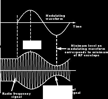
4 2-1: AM Conepts In the modulation proess, the voie, video, or digital signal modifies another signal alled the arrier. In amplitude modulation (AM) the information signal varies the amplitude of the arrier sine wave. The instantaneous value of the arrier amplitude hanges in aordane with the amplitude and frequeny variations of the modulating signal. An imaginary line alled the envelope onnets the positive and negative peaks of the arrier waveform.

5 2-1: AM Conepts
6 2-1: AM Conepts Figure 1-1: Amplitude modulation. (a) The modulating or information signal.
7 2-1: AM Conepts Figure 1-2: Amplitude modulation. (b) The modulated arrier.
8 2-1: AM Conepts In AM, it is partiularly important that the peak value of the modulating signal be less than the peak value of the arrier. V m < V Distortion ours when the amplitude of the modulating signal is greater than the amplitude of the arrier. A modulator is a iruit used to produe AM. Amplitude modulators ompute the produt of the arrier and modulating signals.
9 2-1: AM Conepts Figure 1-3: Amplitude modulator showing input and output signals.
10 The Mathematial Representation and Analysis of AM Representing both the modulating signal V m (t) and the arrier signal V (t) in trigonometri funtions. The AM DSBFC modulator must be able to produe mathematial multipliation of these two analog signals v m ( t) V sin (2 f t) m m v am ( t) [ V V sin (2 f t)] sin (2 f t) m m v ( t) V sin (2 f t) EKT343 Priniple of Communiation Engineering 10
11 Cont d Substituting V m = mv gives: v am ( t) [ V [1 m mv sin (2 f sin (2 f m m t)] V t)] sin (2 f t)] sin (2 f t)] Constant + mod. signal Unmodulated arrier EKT343 Priniple of Communiation Engineering 11
12 Cont d The onstant in the first term produes the arrier freq while the sinusoidal omponent in the first term produes side bands frequenies v am ( t) Carrier frequeny signal (volts) V V sin (2 f t) [ mv sin (2 f t) mv 2 os[2 ( f mv 2 Lower side frequeny signal (volts) sin (2 f os[2 ( f f m ) t] m t)][sin (2 f t)] f m ) t] Upper side frequeny signal (volts) EKT343 Priniple of Communiation Engineering 12
13 Cont d From the equation it is obvious that the amplitude of the arrier is unaffeted by the modulation proess. The amplitude of the side frequenies depend on the both the arrier amplitude and modulation index. At 100% modulation the amplitudes of side frequenies are eah equal to one-half the amplitude of the arrier. EKT343 Priniple of Communiation Engineering 13
 and troughs (V min ).")
14 2-2: Modulation Index and Perentage of Modulation Figure 1-5: AM wave showing peaks (V max ) and troughs (V min ).
15 2-2: Modulation Index and Perentage of Modulation The modulation index (m) is a value that desribes the relationship between the amplitude of the modulating signal and the amplitude of the arrier signal. It is the term used to desribe the amount of amplitude hange(modulation) present in the an AM waveform. m = V m / V This index is also known as the modulating fator or oeffiient, or the degree of modulation. Multiplying the modulation index by 100 gives the perentage of modulation.
16 2-2: Modulation Index and Perentage of Modulation Perentage of Modulation The modulation index is ommonly omputed from measurements taken on the omposite modulated waveform. Using osillosope voltage values: Vm = V max V min 2 The amount, or depth, of AM is then expressed as the perentage of modulation (100 m) rather than as a fration.

17 Determining modulation index from V max and V min EKT343 Priniple of Communiation Engineering 17
18 Cont d Mathematially, the modulation index is m = modulation index E m = peak hange in the amplitude output waveform (sum of voltages from upper and lower side frequenies) E = peak amplitude of the unmodulated arrier m E E m And the perentage of modulation index is Em % m x100% E EKT343 Priniple of Communiation Engineering 18
19 Cont d If the modulating signal is a pure, single-freq sine wave and the proess is symmetrial then the modulation index an be derived as follows: Therefore, E E m ( V ( V max max V V min min ) ) m ( V ( V max max V V min min ) ) ( V ( V max max V V min min ) ) EKT343 Priniple of Communiation Engineering 19
20 Cont d Sine the peak hange of modulated output wave E m is the sum of the usf and lsf voltages hene, E E E where E E m usf lsf usf lsf Then E usf E lsf Em ( V 1 2 max ( V max V 2 min V ) min ) E usf = peak amplitude of the upper side frequeny (volts) E lsf = peak amplitude of the lower side frequeny (volts) EKT343 Priniple of Communiation Engineering 20
21 2-2: Modulation Index and Perentage of Modulation Overmodulation and Distortion The modulation index should be a number between 0 and 1. If the amplitude of the modulating voltage is higher than the arrier voltage, m will be greater than 1, ausing distortion. If the distortion is great enough, the intelligene signal beomes unintelligible.
22 2-2: Modulation Index and Perentage of Modulation Overmodulation and Distortion Distortion of voie transmissions produes garbled, harsh, or unnatural sounds in the speaker. Distortion of video signals produes a srambled and inaurate piture on a TV sreen.

23 2-2: Modulation Index and Perentage of Modulation Figure 1-4: Distortion of the envelope aused by overmodulation where the modulating signal amplitude V m is greater than the arrier signal V.
24 2-3: Sidebands and the Frequeny Domain Side frequenies, or sidebands are generated as part of the modulation proess and our in the frequeny spetrum diretly above and below the arrier frequeny.
25 Sideband Calulations 2-3: Sidebands and the Frequeny Domain Single-frequeny sine-wave modulation generates two sidebands. Complex wave (e.g. voie or video) modulation generates a range of sidebands. The upper sideband (f USB ) and the lower sideband (f LSB ) are alulated: f USB = f + f m and f LSB = f f m
 Intelligene or modulating signal. (b) Lower sideband. ( ) Carrier. (d ) Upper sideband. (e ) Composite AM wave.")
26 2-3: Sidebands and the Frequeny Domain Figure 1-6: The AM wave is the algebrai sum of the arrier and upper and lower sideband sine waves. (a) Intelligene or modulating signal. (b) Lower sideband. ( ) Carrier. (d ) Upper sideband. (e ) Composite AM wave.
27 2-3: Sidebands and the Frequeny Domain Frequeny-Domain Representation of AM Observing an AM signal on an osillosope, you see only amplitude variations of the arrier with respet to time. A plot of signal amplitude versus frequeny is referred to as frequeny-domain display. A spetrum analyzer is used to display the frequeny domain as a signal. Bandwidth is the differene between the upper and lower sideband frequenies. BW = f USB f LSB = [f + f m(max) ] [f f m(max) ] = 2f m(max)
28 2-3: Sidebands and the Frequeny Domain Figure 1-8: The relationship between the time and frequeny domains.
29 2-3: Sidebands and the Frequeny Domain Frequeny-Domain Representation of AM Example 1: For a onventional AM modulator with a arrier freq of f = 100 khz and the maximum modulating signal frequeny of f m(max) = 5 khz, determine: a) Freq limits for the upper and lower sidebands. b) Bandwidth. ) Upper and lower side frequenies produed when the modulating signal is a single-freq 3-kHz tone. d) Draw the output freq spetrum.
30 Solution: Example 1
31
32 Example 2 Suppose that V max value read from the gratiule on an osillosope sreen is 4.6 divisions and V min is 0.7 divisions. Calulate the modulation index and perentage of modulation. EKT343 Priniple of Communiation Engineering 32
33
34 Example 3 For the AM waveform shown in Figure below, determine a) Peak amplitude of the upper and lower side frequenies. b) Peak amplitude of the unmodulated arrier. ) Peak hange in the amplitude of the envelope. d) Modulation index. e) Perent modulation. EKT343 Priniple of Communiation Engineering 34

35 AM Envelope for Example 3 EKT343 Priniple of Communiation Engineering 35
36

37 Generation of AM DSBFC envelope showing the timedomain of the modulated wave, arrier & sideband signals EKT343 Priniple of Communiation Engineering 37
38 Voltage spetrum for an AM DSBFC wave EKT343 Priniple of Communiation Engineering 38
39 Example 4 One input to a onventional AM modulator is a 500-kHz arrier with an amplitude of 20 V p. The seond input is a 10-kHz modulating signal that is of suffiient amplitude to ause a hange in the output wave of ±7.5 V p. Determine a) Upper and lower side frequenies. b) Modulation index and perentage modulation. ) Peak amplitude of the modulated arrier and the upper and lower side frequeny voltages. d) Maximum and minimum amplitudes of the envelope. e) Expression for the modulated wave. EKT343 Priniple of Communiation Engineering 39
40
41
42 2-3: Sidebands and the Frequeny Domain Pulse Modulation When omplex signals suh as pulses or retangular waves modulate a arrier, a broad spetrum of sidebands is produed. A modulating square wave will produe sidebands based on the fundamental sine wave as well as the third, fifth, seventh, et. harmonis. Amplitude modulation by square waves or retangular pulses is referred to as amplitude shift keying (ASK). ASK is used in some types of data ommuniations.
43 2-3: Sidebands and the Frequeny Domain Figure 1-11: Frequeny spetrum of an AM signal modulated by a square wave.
44 2-3: Sidebands and the Frequeny Domain Figure 1-12: Amplitude modulation of a sine wave arrier by a pulse or retangular wave is alled amplitude-shift keying. (a) Fifty perent modulation. (b) One hundred perent modulation.
45 Pulse Modulation 2-3: Sidebands and the Frequeny Domain Continuous-wave (CW) transmission an be ahieved by turning the arrier off and on, as in Morse ode transmission. Continuous wave (CW) transmission is sometimes referred to as On-Off keying (OOK). Splatter is a term used to desribe harmoni sideband interferene.
46 2-4: Single-Sideband Modulation In amplitude modulation, two-thirds of the transmitted power is in the arrier, whih onveys no information. Signal information is ontained within the sidebands. Single-sideband (SSB) is a form of AM where the arrier is suppressed and one sideband is eliminated.
47 2-4: Single-Sideband Modulation DSB Signals The first step in generating an SSB signal is to suppress the arrier, leaving the upper and lower sidebands. This type of signal is alled a double-sideband suppressed arrier (DSSC) signal. No power is wasted on the arrier. A balaned modulator is a iruit used to produe the sum and differene frequenies of a DSSC signal but to anel or balane out the arrier. DSB (or DSSC) is not widely used beause the signal is diffiult to demodulate (reover) at the reeiver.
48 2-4: Single-Sideband Modulation Figure 1-16: A frequeny-domain display of DSB signal.
49 2-4: Single-Sideband Modulation SSB Signals One sideband is all that is neessary to onvey information in a signal. A single-sideband suppressed arrier (SSSC) signal is generated by suppressing the arrier and one sideband.
50 2-4: Single-Sideband Modulation SSB Signals SSB signals offer four major benefits: 1. Spetrum spae is onserved and allows more signals to be transmitted in the same frequeny range. 2. All power is hanneled into a single sideband. This produes a stronger signal that will arry farther and will be more reliably reeived at greater distanes. 3. Oupied bandwidth spae is narrower and noise in the signal is redued. 4. There is less seletive fading over long distanes.
51 2-4: Single-Sideband Modulation Disadvantages of DSSC and SSBSC Single and double-sideband SC s are not widely used beause the signals are diffiult to reover (i.e. demodulate) at the reeiver. A low power, pilot arrier is sometimes transmitted along with sidebands in order to more easily reover the signal at the reeiver.
52 2-4: Single-Sideband Modulation Signal Power Considerations In SSB, the transmitter output is expressed in terms of peak envelope power (PEP), the maximum power produed on voie amplitude peaks. Appliations of DSB and SSB A vestigial sideband signal (VSB) is produed by partially suppressing the lower sideband. This kind of signal is used in TV transmission.
53 2-5: AM Power In radio transmission, the AM signal is amplified by a power amplifier. A radio antenna has a harateristi impedane that is ideally almost pure resistane. The AM signal is a omposite of the arrier and sideband signal voltages. Eah signal produes power in the antenna. Total transmitted power (P T ) is the sum of arrier power (P ) and power of the two sidebands (P USB and P LSB ).
54 2-5: AM Power When the perentage of modulation is less than the optimum 100, there is muh less power in the sidebands. Output power an be alulated by using the formula P T = (I T ) 2 R where I T is measured RF urrent and R is antenna impedane
55 2-5: AM Power The greater the perentage of modulation, the higher the sideband power and the higher the total power transmitted. Power in eah sideband is alulated P SB = P LSB = P USB = P m 2 / 4 Maximum power appears in the sidebands when the arrier is 100 perent modulated.
56 AM Power Review: onventional AM(DSB-FC) Frequeny spetrum: f -f m f f +f m Bandwidth=2 x f mmax Total Power=P arrier +P usb +P lsb EKT343 Priniple of Communiation Engineering 56
57 DSB FULL CARRIER
58 Two major Drawbaks of DSBFC Large power onsumption, where arrier power onstitutes >2/3 transmitted power.{remember : arrier does not ontain any information} Utilize twie as muh bandwidth both the upper and lower sideband atually ontains same information (redundant). Thus, DSBFC is both power and bandwidth ineffiient EKT343 Priniple of Communiation Engineering 58
59 Double side band suppressed arrier(dsb-sc) Frequeny spetrum: f -f m f f +f m Bandwidth:2 x f mmax Total Power= P usb + P lsb EKT343 Priniple of Communiation Engineering 59
60 Single-Sideband (SSB) The arrier is transmitted at full power but only one sideband is transmitted requires half the bandwidth of DSBFC AM Carrier power onstitutes 80% of total transmitted power, while sideband power onsumes 20% SSBFC requires less total power but utilizes a smaller perentage of the power to arry the information EKT343 Priniple of Communiation Engineering 60
61 Single Side Band Full Carrier (SSB-FC) Frequeny spetrum: f -f m f f +f m Bandwidth=f mmax Total Power=P arrier +P usb EKT343 Priniple of Communiation Engineering 61
62 AM Single-Sideband Suppressed Carrier (SSBSC) The arrier is totally suppressed and one sideband is removed requires half the bandwidth of DSBFC AM Considerably less power than DSBFC and SSBFC shemes Sideband power makes up 100% of the total transmitted power The wave is not an envelope but a sine wave at frequeny equal to the arrier frequeny ±modulating frequeny (depending on whih sideband is transmitted) EKT343 Priniple of Communiation Engineering 62
63 Single Side band Suppress Carrier (SSB-SC) Frequeny spetrum: f -f m f f +f m Bandwidth=f mmax Total Power=+P usb EKT343 Priniple of Communiation Engineering 63
64 AM Single-Sideband Redued Carrier (SSBRC) One sideband is totally removed and the arrier voltage is redued to approximately 10% of its unmodulated amplitude requires half the bandwidth of DSBFC AM Less transmitted power than DSBFC and SSBFC but more power than SSBSC As muh as 96% of the total transmitted power is in the sideband The output modulated signal is similar to SSBFC but with redued maximum and minimum envelope amplitudes EKT343 Priniple of Communiation Engineering 64

65 Comparison of time domain representation of three ommon AM transmission systems: Tomasi Eletroni Communiations Systems, 5e EKT343 Priniple of Communiation Engineering 65
66 Example 5 For an AM DSBFC wave with a peak unmodulated arrier voltage V = 10Vp, frequeny of 100kHz, a load resistor of RL = 10, frequeny of modulating signal of 10kHz and m = 1, determine the following i) Powers of the arrier and the upper and lower sidebands. ii) Total power of the modulated wave. iii) Bandwidth of the transmitted wave. iv) Draw the power and frequeny spetrum. EKT343 Priniple of Communiation Engineering 66
67 Example 5..ont d Solution for DSBFC; i) ii) P P usb ( V P lsb / R ) V (10) 2R m P 1.25W 4 5W P t 2 m P P (5) 4 4 m 4 2 (5) P 7.5W iii) Bandwidth=2xf mmax =2(10kHz)=20kHz EKT343 Priniple of Communiation Engineering 67
68 Example 5..ont d For the same given values, determine questions (ii)-(iv) for a AM DSB-SC, AM SSB-FC and AM SSB-SC systems. Determine also the perentage of power saved in eah of the system design. EKT343 Priniple of Communiation Engineering 68
69 Example 5..ont d Solution: For DSB-SC ii) P t m m P P (5) (5) 4 2.5W Power 5W saved % Power 66.67% saved 7.5W 2.5W 5W x100% 7.5W iii)bandwidth=2xf mmax =2(10kHz)=20kHz iv) 90kHz 110kHz EKT343 Priniple of Communiation Engineering 69
70 Example 5..ont d Solution:For SSB-FC ii) P t 2 m P P (5) W Power saved 1.25W % Power 16.67% saved 7.5W 6.25W 1.25W x100% 7.5W iii)bandwidth=f mmax =10kHz iv) f -f m 100kHz 110kHz EKT343 Priniple of Communiation Engineering 70
71 Example 5..ont d Solution:For SSB-SC ii) P t 2 m P (5) W Power saved 6.25W % Power 83.33% saved 7.5W 1.25W 6.25W x100% 7.5W iii)bandwidth=f mmax =10kHz iv) f -f m f 110kHz EKT343 Priniple of Communiation Engineering 71
72 Exerises 1. An audio signal 15sin2π (1500t ). Amplitude modulates a arrier 60sin2π (100000t). a) Sketh the audio signal b) Sketh the arrier ) Construt the modulated wave d) Determine the modulation index and perent modulation e) What are the frequenies of the audio signal and the arrier f) What frequenies would show up in the spetrum analysis of the modulated wave.
73 Exerises 2. The total power ontent of an AM wave is 600W. Determine the perent modulation of the signal if eah of the sidebands ontains 75W. 3. Determine the power ontent of the arrier and eah of the sidebands for an AM signal having a perent modulation of 80% and the total power of 2500W
74 Methods of Generating SSB 2 methods, i) Filtering method A filter removes the undesired sideband produing SSB. Quartz rystal filters are the most widely used sideband filters sine they are very seletive and inexpensive. ii) Phasing method A balaned modulator eliminates the arrier and provides DSB. EKT343 Priniple of Communiation Engineering 74


75 Filtering method Carrier osillator Mirophone Audio amplifier Balaned modulator DSB signal Sideband filter Lower Upper sidebands sidebands SSB signal Linear amplifier Filter response urve Antenna EKT343 Priniple of Communiation Engineering 75
76 Phasing methods-using two balane modulator Another way to produe SSB uses a phase shift method to eliminate one sideband. Two balaned modulators driven by arriers and modulating signals 90º out of phase produe DSB. Adding the two DSB signals together results in one sideband being anelled out. EKT343 Priniple of Communiation Engineering 76
77 Phasing method..ont d Information signal Am os wmt Carrier signal Balaned Modulator 1 Phase shifter A 1 (t) A os (wt + 90) + Output Signal, a o t Phase shifter Am os (wmt + 90) Balaned Modulator 2 A 2 (t) EKT343 Priniple of Communiation Engineering 77
78 Phasing method..ont d a ( t) 0 a ( t) a ( t) a ( t) a 1 A 2 os( w t ( t) 90 0 )* A (1) os w t 0 0 A A os( w t 90 w t) A A os( w t 90 w t) (2) m A os( w t)* A m m os( w t m A A os( w t 90 w t) A A os( w t 90 w t) (3) m a 0 ( t) A A m m (2) m m (3) os( w t m 0 m ) 90 0 w t) m m m EKT343 Priniple of Communiation Engineering 78
79 Advantages/Disadvantages of SSB Advantages Power onsumption - Muh less total transmitted power is neessary to produe the same quality signal as ahieved with DSBFC AM Bandwidth onservation Seletive fading - arrier phase shift and arrier fading an not our, thus smaller distortion is expeted. Noise redution - thermal noise power is redued Disadvantages Complex reeivers Tuning diffiulties requires more omplex and preise than DSB EKT343 Priniple of Communiation Engineering 79
80 VESTIGIAL SIDEBAND (VSB) VSB is similar to SSB but it retains a small portion (a vestige) of the undesired sideband to redue DC distortion. VSB signals are generated using standard AM or DSBSC modulation, then passing modulated signal through a sideband shaping filter. Demodulation uses either standard AM or DSBSC demodulation. EKT343 Priniple of Communiation Engineering 80
81 Cont d Also alled asymmetri sideband system. Compromise between DSB & SSB. Easy to generate. Bandwidth is only ~ 25% greater than SSB signals. Derived by filtering DSB, one pass band is passed almost ompletely while just a trae or vestige of the other sideband is inluded. EKT343 Priniple of Communiation Engineering 81
82 Cont d AM wave is applied to a vestigial sideband filter, produing a modulation sheme VSB + C Mainly used for television video transmission. VSB Frequeny Spetrum Carrier VSB LSB MSB f EKT343 Priniple of Communiation Engineering 82
CHAPTER 2! AMPLITUDE MODULATION (AM)
") CHAPTER 2 AMPLITUDE MODULATION (AM) Topics 2-1 : AM Concepts 2-2 : Modulation Index and Percentage of Modulation 2-3 : Sidebands and the Frequency Domain 2-4 : Single-Sideband Modulation 2-5 : AM Power
CHAPTER 2 AMPLITUDE MODULATION (AM) Topics 2-1 : AM Concepts 2-2 : Modulation Index and Percentage of Modulation 2-3 : Sidebands and the Frequency Domain 2-4 : Single-Sideband Modulation 2-5 : AM Power
CHAPTER 2. AMPLITUDE MODULATION (AM) 2.3 AM Single Side Band Communications
 2.3 AM Single Side Band Communications") CHAPTER AMPLITUDE MODULATION (AM).3 AM Single Side Band Couniations OBJECTIVES To define and desribe AM single sideband To opare single sideband transission to onventional double sideband AM The explain
CHAPTER AMPLITUDE MODULATION (AM).3 AM Single Side Band Couniations OBJECTIVES To define and desribe AM single sideband To opare single sideband transission to onventional double sideband AM The explain
Chapter 3. Amplitude Modulation Fundamentals
 Chapter 3 Amplitude Modulation Fundamentals Topics Covered 3-1: AM Concepts 3-2: Modulation Index and Percentage of Modulation 3-3: Sidebands and the Frequency Domain 3-4: AM Power 3-5: Single-Sideband
Chapter 3 Amplitude Modulation. Wireless Information Transmission System Lab. Institute of Communications Engineering National Sun Yat-sen University
 Chapter 3 Amplitude Modulation Wireless Information Transmission System Lab. Institute of Communiations Engineering National Sun Yat-sen University Outline 3.1 Introdution 3.2 Amplitude Modulation 3.3
Figure 4.11: Double conversion FM receiver
 74 4.8 FM Reeivers FM reeivers, like their AM ounterparts, are superheterodyne reeivers. Figure 4.11 shows a simplified blok diagram for a double onversion superheterodyne FM reeiver Figure 4.11: Double
EE140 Introduction to Communication Systems Lecture 7
 3/4/08 EE40 Introdution to Communiation Systems Leture 7 Instrutor: Prof. Xiliang Luo ShanghaiTeh University, Spring 08 Arhiteture of a (Digital) Communiation System Transmitter Soure A/D onverter Soure
ELEC 350 Communications Theory and Systems: I. Analog Signal Transmission and Reception. ELEC 350 Fall
 ELEC 350 Communiations Theory and Systems: I Analog Signal Transmission and Reeption ELEC 350 Fall 2007 1 ELEC 350 Fall 2007 2 Analog Modulation A large number o signals are analog speeh musi video These
6. Amplitude Modulation
 6. Amplitude Modulation Modulation is a proess by whih some parameter of a arrier signal is varied in aordane with a message signal. The message signal is alled a modulating signal. Definitions A bandpass
Dr. Md. Farhad Hossain Associate Professor Department of EEE, BUET
 EEE 309 Communiation Theory Semester: January 06 Dr. Md. Farhad Hossain Assoiate Proessor Department o EEE, BUET Email: marhadhossain@eee.buet.a.bd Oie: ECE 33, ECE Building Part 03-3 Single-sideband Suppressed
Amplitude Modulation Fundamentals
 3 chapter Amplitude Modulation Fundamentals In the modulation process, the baseband voice, video, or digital signal modifies another, higher-frequency signal called the carrier, which is usually a sine
TELE3013 Mid-session QUIZ 1
 TELE3013 Mid-session QUIZ 1 Week 7 10 th April, 2006 Name: Student No: Instrutions to Candidates (1) Time allowed: 90 minutes or so (2) Answer all questions. Total Marks = 90. (3) Marks are as indiated.
ENSC327 Communications Systems 4. Double Sideband Modulation. Jie Liang School of Engineering Science Simon Fraser University
 ENSC327 Communiations Systems 4. Double Sideband Modulation Jie Liang Shool of Engineering Siene Simon Fraser University 1 Outline DSB: Modulator Spetrum Coherent Demodulator: Three methods Quadrature-arrier
ENSC327 Communications Systems 4. Double Sideband Modulation. School of Engineering Science Simon Fraser University
 ENSC327 Communiations Systems 4. Double Sideband Modulation Shool of Engineering Siene Simon Fraser University 1 Outline Required Bakground DSB: Modulator Spetrum Coherent Demodulator: Three methods Quadrature-arrier
Objectives. Presentation Outline. Digital Modulation Lecture 04
 Digital Modulation Leture 04 Filters Digital Modulation Tehniques Rihard Harris Objetives To be able to disuss the purpose of filtering and determine the properties of well known filters. You will be able
Analog Communications
 1 Analog Communiations Amplitude Modulation (AM) Frequeny Modulation (FM) 2 Radio broadasting 30-300M Hz SOURCE Soure Transmitter Transmitted signal Channel Reeived signal Reeiver User Analog baseband
Amplitude Modulated Systems
 Amplitude Modulated Systems Communication is process of establishing connection between two points for information exchange. Channel refers to medium through which message travels e.g. wires, links, or
Introduction to Analog And Digital Communications
 Introdution to Analog And Digital Communiations Seond Edition Simon Haykin, Mihael Moher Chapter 9 Noise in Analog Communiations 9.1 Noise in Communiation Systems 9. Signal-to-Noise Ratios 9.3 Band-Pass
EE (082) Chapter IV: Angle Modulation Lecture 21 Dr. Wajih Abu-Al-Saud
 Chapter IV: Angle Modulation Lecture 21 Dr. Wajih Abu-Al-Saud") EE 70- (08) Chapter IV: Angle Modulation Leture Dr. Wajih Abu-Al-Saud Effet of Non Linearity on AM and FM signals Sometimes, the modulated signal after transmission gets distorted due to non linearities
EE 70- (08) Chapter IV: Angle Modulation Leture Dr. Wajih Abu-Al-Saud Effet of Non Linearity on AM and FM signals Sometimes, the modulated signal after transmission gets distorted due to non linearities
Communication Systems Lecture 7. Dong In Kim School of Info/Comm Engineering Sungkyunkwan University
 Communiation Systems Leture 7 Dong In Kim Shool o Ino/Comm Engineering Sungkyunkwan University 1 Outline Expression o SSB signals Waveorm o SSB signals Modulators or SSB: Frequeny disrimination Phase disrimination
Generating 4-Level and Multitone FSK Using a Quadrature Modulator
 Generating 4-Level and Multitone FSK Using a Quadrature Modulator Page 1 of 9 Generating 4-Level and Multitone FSK Using a Quadrature Modulator by In a reent olumn (lik on the Arhives botton at the top
Analog Transmission of Digital Data: ASK, FSK, PSK, QAM
 Analog Transmission of Digital Data: ASK, FSK, PSK, QAM Required reading: Forouzan 5. Garia 3.7 CSE 33, Fall 6 Instrutor: N. Vlaji Why Do We Need Digital-to-Analog Conversion?! ) The transmission medium
Introductory Notions
 Introdutory Notions - he blok diagram of a transmission link, whih onveys information by means of eletromagneti signals, is depited in the figure below. Message Signal aqusition blok Information ransmitter
ANALOG COMMUNICATION (9)
") 11/5/013 DEARTMENT OF ELECTRICAL &ELECTRONICS ENGINEERING ANALOG COMMUNICATION (9) Fall 013 Original slides by Yrd. Doç. Dr. Burak Kellei Modified by Yrd. Doç. Dr. Didem Kivan Tureli OUTLINE Noise in Analog
11/5/013 DEARTMENT OF ELECTRICAL &ELECTRONICS ENGINEERING ANALOG COMMUNICATION (9) Fall 013 Original slides by Yrd. Doç. Dr. Burak Kellei Modified by Yrd. Doç. Dr. Didem Kivan Tureli OUTLINE Noise in Analog
BPSK so that we have a discrete set of RF signals. t)cos(
cos(") BPSK. BPSK Introdution Reall that the most general modulation has the form s( t) a( t)os[ t ( t)]. We remared earlier that phase modulation was not an effetive way to implement analog ommuniation, one
BPSK. BPSK Introdution Reall that the most general modulation has the form s( t) a( t)os[ t ( t)]. We remared earlier that phase modulation was not an effetive way to implement analog ommuniation, one
Revision: April 18, E Main Suite D Pullman, WA (509) Voice and Fax
 Voice and Fax") Lab 9: Steady-state sinusoidal response and phasors Revision: April 18, 2010 215 E Main Suite D Pullman, WA 99163 (509) 334 6306 Voie and Fax Overview In this lab assignment, we will be onerned with the
Lab 9: Steady-state sinusoidal response and phasors Revision: April 18, 2010 215 E Main Suite D Pullman, WA 99163 (509) 334 6306 Voie and Fax Overview In this lab assignment, we will be onerned with the
Chapter 3 Digital Transmission Fundamentals
 Chapter 3 Digital Transmission Fundamentals Modems and Digital Modulation CSE 33, Winter Instrutor: Foroohar Foroozan Modulation of Digital Data Modulation of Digital Data Modulation proess of onverting
CHAPTER 3 BER EVALUATION OF IEEE COMPLIANT WSN
 CHAPTER 3 EVALUATIO OF IEEE 8.5.4 COMPLIAT WS 3. OVERVIEW Appliations of Wireless Sensor etworks (WSs) require long system lifetime, and effiient energy usage ([75], [76], [7]). Moreover, appliations an
Single Sideband (SSB) AM
 AM") Single Sideband (SSB) AM Leture 7 Why SSB-AM? Spetral eiieny is o great importane. Conventional & DSB-SC oupy twie the message bandwidth. All the inormation is ontained in either hal the other is redundant.
Single Sideband (SSB) AM Leture 7 Why SSB-AM? Spetral eiieny is o great importane. Conventional & DSB-SC oupy twie the message bandwidth. All the inormation is ontained in either hal the other is redundant.
Digitally Demodulating Binary Phase Shift Keyed Data Signals
 Digitally Demodulating Binary Phase Shift Keyed Signals Cornelis J. Kikkert, Craig Blakburn Eletrial and Computer Engineering James Cook University Townsville, Qld, Australia, 4811. E-mail: Keith.Kikkert@ju.edu.au,
Module 5 Carrier Modulation. Version 2 ECE IIT, Kharagpur
 Module 5 Carrier Modulation Version ECE II, Kharagpur Lesson 5 Quaternary Phase Shift Keying (QPSK) Modulation Version ECE II, Kharagpur After reading this lesson, you will learn about Quaternary Phase
UNIT-I AMPLITUDE MODULATION (2 Marks Questions and Answers)
") UNIT-I AMPLITUDE MODULATION (2 Marks Questions and Answers) 1. Define modulation? Modulation is a process by which some characteristics of high frequency carrier Signal is varied in accordance with the
UNIT-I AMPLITUDE MODULATION (2 Marks Questions and Answers) 1. Define modulation? Modulation is a process by which some characteristics of high frequency carrier Signal is varied in accordance with the
ANALOG COMMUNICATIONS IV Sem. Prepared by Mr. T. Nagarjuna ECE Department
 ANALOG COMMUNICAIONS IV Sem Prepared by Mr.. Nagaruna ECE Department UNI I SIGNAL ANALYSIS AND LI SYSEMS Classifiation of Signals Deterministi & Non Deterministi Signals Periodi & A periodi Signals Even
and division (stretch).
.") Filterg AC signals Topi areas Eletrial and eletroni engeerg: AC Theory. Resistane, reatane and impedane. Potential divider an AC iruit. Low pass and high pass filters. Mathematis: etor addition. Trigonometry.
Filterg AC signals Topi areas Eletrial and eletroni engeerg: AC Theory. Resistane, reatane and impedane. Potential divider an AC iruit. Low pass and high pass filters. Mathematis: etor addition. Trigonometry.
Amplitude Modulation. Ahmad Bilal
 Amplitude Modulation Ahmad Bilal 5-2 ANALOG AND DIGITAL Analog-to-analog conversion is the representation of analog information by an analog signal. Topics discussed in this section: Amplitude Modulation
Considerations and Challenges in Real Time Locating Systems Design
 Considerations and Challenges in Real Time Loating Systems Design Dr. Brian Gaffney DeaWave Ltd. Email: brian.gaffney@deawave.om Abstrat Real Time Loating Systems (RTLS) are a ombination of hardware and
Fatih University Electrical and Electronics Engineering Department EEE Communications I EXPERIMENT 5 FM MODULATORS
 Fatih University Eletrial and Eletronis Engineering epartent EEE 36 - Couniations I EXPERIMENT 5 FM MOULATORS 5. OBJECTIVES. Studying the operation and harateristis of a varator diode.. Understanding the
DSP First Lab 05: FM Synthesis for Musical Instruments - Bells and Clarinets
 DSP First Lab 05: FM Synthesis for Musial Instruments - Bells and Clarinets Pre-Lab and Warm-Up: You should read at least the Pre-Lab and Warm-up setions of this lab assignment and go over all exerises
Calculation of the maximum power density (averaged over 4 khz) of an angle modulated carrier
 of an angle modulated carrier") Re. ITU-R SF.675-3 1 RECOMMENDATION ITU-R SF.675-3 * CALCULATION OF THE MAXIMUM POWER DENSITY (AVERAGED OVER 4 khz) OF AN ANGLE-MODULATED CARRIER Re. ITU-R SF.675-3 (199-1992-1993-1994) The ITU Radioommuniation
Re. ITU-R SF.675-3 1 RECOMMENDATION ITU-R SF.675-3 * CALCULATION OF THE MAXIMUM POWER DENSITY (AVERAGED OVER 4 khz) OF AN ANGLE-MODULATED CARRIER Re. ITU-R SF.675-3 (199-1992-1993-1994) The ITU Radioommuniation
Research on Blanket Jamming to Beidou Navigation Signals Based on BOC Modulation
 Int. J. Communiations, Network and System Sienes, 6, 9, 35-44 Published Online May 6 in SiRes. http://www.sirp.org/ournal/ins http://dx.doi.org/.436/ins.6.95 Researh on Blanket Jamming to Beidou Navigation
Lecture Notes On Analogue Communication Techniques(Module 1 & 2) Topics Covered: 1. Spectral Analysis of Signals 2. Amplitude Modulation Techniques
 Topics Covered: 1. Spectral Analysis of Signals 2. Amplitude Modulation Techniques") Leture Notes On Analogue Communiation Tehniques(Module 1 & ) Topis Covered: 1. Spetral Analysis of Signals. Amplitude Modulation Tehniques 3. Angle Modulation 4. Mathematial Representation of Noise 5.
Leture Notes On Analogue Communiation Tehniques(Module 1 & ) Topis Covered: 1. Spetral Analysis of Signals. Amplitude Modulation Tehniques 3. Angle Modulation 4. Mathematial Representation of Noise 5.
Principles of Communications
 Priniples of Communiations Meixia Tao Dept. of Eletroni Engineering Shanghai Jiao Tong University Chapter 3: Analog Modulation Seleted from Ch 3, Ch 4.-4.4, Ch 6.-6. of of Fundamentals of Communiations
Fatih University Electrical and Electronics Engineering Department EEE Communications I EXPERIMENT 4 AM DEMODULATORS
 Fatih University Eletrial and Eletronis Engineering Departent EEE 316 - Couniations I EXPERIMENT 4 AM DEMODULATORS 4.1 OBJECTIVES 1. Understanding the priniple of aplitude odulation and deodulation.. Ipleenting
Calculating the input-output dynamic characteristics. Analyzing dynamic systems and designing controllers.
 CHAPTER : REVIEW OF FREQUENCY DOMAIN ANALYSIS The long-term response of a proess is nown as the frequeny response whih is obtained from the response of a omplex-domain transfer funtion. The frequeny response
Metrol. Meas. Syst., Vol. XVIII (2011), No. 2, pp METROLOGY AND MEASUREMENT SYSTEMS. Index , ISSN
, No. 2, pp METROLOGY AND MEASUREMENT SYSTEMS. Index , ISSN") METROLOGY AND MEASUREMENT SYSTEMS Index 330930, ISSN 0860-8229 www.metrology.pg.gda.pl DAC TESTING USING MODULATED SIGNALS Pavel Fexa, Josef Vedral, Jakub Svatoš CTU Prague, Faulty of Eletrial Engineering
METROLOGY AND MEASUREMENT SYSTEMS Index 330930, ISSN 0860-8229 www.metrology.pg.gda.pl DAC TESTING USING MODULATED SIGNALS Pavel Fexa, Josef Vedral, Jakub Svatoš CTU Prague, Faulty of Eletrial Engineering
Outline. Communications Engineering 1
 Outline Introduction Signal, random variable, random process and spectra Analog modulation Analog to digital conversion Digital transmission through baseband channels Signal space representation Optimal
Introduction & Amplitude Modulation
 Departent of Eletronis and Couniation Engineering, KUET Introdution & Aplitude Modulation Dr. Monir Hossen ECE, KUET Departent of Eletronis and Couniation Engineering, KUET Introdution (1/) Long distane
Parameters of the radio channels that affect digital signal transmissions Propagation Environment Attenuation Index, γ
 Parameters of the radio hannels that affet digital signal transmissions 1.Free spae attenuation - the signal undergoes an average attenuation that depends on the length of the path and signal s frequeny
AMPLITUDE MODULATION AND DEMODULATION
 Modulation is a tehnique to transit inforation via radio arrier wavefor. It is a non-linear proess that generates additional frequenies, as we will see. Aplitude Modulation (AM) works by varying the aplitude
ELG3175 Introduction to Communication Systems. Conventional AM
 ELG317 Introdution to Communiation Systems Conventional AM Disadvantages o DSB-SC The reeiver must generate a replia o the arrier in order to demodulate a DSB-SC signal. Any phase and/or requeny error
Micro-Piezoelectric Head Technology of Color Inkjet Printer
 DPP2: International Conferene on Digital Prodution Printing and Industrial Appliations Miro-Piezoeletri Head Tehnology of Color Inkjet Printer Takao Mimura & Shinri Sakai SEIKO EPSON Corporation Shiojiri-shi,
AM Limitations. Amplitude Modulation II. DSB-SC Modulation. AM Modifications
 Lecture 6: Amplitude Modulation II EE 3770: Communication Systems AM Limitations AM Limitations DSB-SC Modulation SSB Modulation VSB Modulation Lecture 6 Amplitude Modulation II Amplitude modulation is
Copyright Blind Selected Mapping Techniques for Space-Time Block Coded Filtered Single-Carrier Signals
 Blind Seleted Mapping Tehniques for Spae-Time Blok Coded Filtered Single-Carrier Signals IEEE VTS AWCS 6 6 August 6 @ Tokyo, Japan Amnart Boonkaay Fumiyuki Adahi Wireless Signal roessing Researh Group
EE 464 Band-Pass Sampling Example Fall 2018
 EE 464 Band-Pass Sampling Example Fall 2018 Summary This example demonstrates the use of band-pass sampling. First, a band-pass signal is onstruted as a osine modulated speeh signal. This is a double sideband
Amplitude Modulation II
 Lecture 6: Amplitude Modulation II EE 3770: Communication Systems Lecture 6 Amplitude Modulation II AM Limitations DSB-SC Modulation SSB Modulation VSB Modulation Multiplexing Mojtaba Vaezi 6-1 Contents
Interpreting CDMA Mobile Phone Testing Requirements
 Appliation Note 54 nterpreting CDMA Mobile Phone Testing Requirements Most people who are not intimately familiar with the protool involved with S-95A & J- STD-008 (CDMA) phones will enounter some onfusion
A 24 GHz Band FM-CW Radar System for Detecting Closed Multiple Targets with Small Displacement
 A 24 GHz Band FM-CW Radar System for Deteting Closed Multiple Targets with Small Displaement Kazuhiro Yamaguhi, Mitsumasa Saito, Takuya Akiyama, Tomohiro Kobayashi and Hideaki Matsue Tokyo University of
2. Continuous-wave modulation
 . Continuous-wave odulation 1. Appliation goal We study representations in tie and frequeny doain for two types of ontinuous wave odulation: aplitude odulation (AM) and frequeny odulation (FM).. Continuous-wave
Outline : Wireless Networks Lecture 6: Physical Layer Coding and Modulation 1. Basic Modulation Techniques. From Signals to Packets.
 Outline 18-759 : Wireless Networks Leure 6: Physial Layer Coding and Modulation 1 Peter Steenkiste Departments of Computer Siene and Elerial and Computer Engineering Spring Semester 2016 http://www.s.mu.edu/~prs/wirelesss16/
Speech, music, images, and video are examples of analog signals. Each of these signals is characterized by its bandwidth, dynamic range, and the
 Speech, music, images, and video are examples of analog signals. Each of these signals is characterized by its bandwidth, dynamic range, and the nature of the signal. For instance, in the case of audio
ANALOG COMMUNICATION (8)
") /5/3 DEPARTMENT OF ELECTRICAL &ELECTRONICS ENGINEERING ANALOG COMMUNICATION (8) Fall 3 Original slides by Yrd. Doç. Dr. Burak Kellei Modified by Yrd. Doç. Dr. Didem Kivan Tureli OUTLINE Random Variables
/5/3 DEPARTMENT OF ELECTRICAL &ELECTRONICS ENGINEERING ANALOG COMMUNICATION (8) Fall 3 Original slides by Yrd. Doç. Dr. Burak Kellei Modified by Yrd. Doç. Dr. Didem Kivan Tureli OUTLINE Random Variables
A Study on The Performance of Multiple-beam Antenna Satellite Receiving System Dezhi Li, Bo Zeng, Qun Wu*
 16 nd International Conferene on Mehanial, Eletroni and Information Tehnology Engineering (ICMITE 16) ISBN: 978-1-6595-34-3 A Study on The Performane of Multiple-beam Antenna Satellite Reeiving System
Capacitor Voltage Control in a Cascaded Multilevel Inverter as a Static Var Generator
 Capaitor Voltage Control in a Casaded Multilevel Inverter as a Stati Var Generator M. Li,J.N.Chiasson,L.M.Tolbert The University of Tennessee, ECE Department, Knoxville, USA Abstrat The widespread use
Amplitude Modulation Chapter 2. Modulation process
 Question 1 Modulation process Modulation is the process of translation the baseband message signal to bandpass (modulated carrier) signal at frequencies that are very high compared to the baseband frequencies.
Average Current Mode Interleaved PFC Control
 Freesale Semiondutor, n. oument Number: AN557 Appliation Note ev. 0, 0/06 Average Current Mode nterleaved PFC Control heory of operation and the Control oops design By: Petr Frgal. ntrodution Power Fator
Amplitude Modulation. Amplitude Modulation. Amplitude Modulation. Amplitude Modulation. A. Introduction. A. Introduction
 1. In AM modulation we impart the information of a message signal m(t) on to a sinusoidal carrier c(t). This results in the translation of the message signal to a new frequency range. The motivation for
Introduction to Amplitude Modulation
 1 Introduction to Amplitude Modulation Introduction to project management. Problem definition. Design principles and practices. Implementation techniques including circuit design, software design, solid
Communication Systems, 5e
 Communiation Systems, 5e Chapter 7: Analog Communiation Systems A. Brue Carlson Paul B. Crilly 010 The Mraw-Hill Companies Chapter 7: Analog Communiation Systems Reeiver blok diagram design Image requeny
B.Tech II Year II Semester (R13) Supplementary Examinations May/June 2017 ANALOG COMMUNICATION SYSTEMS (Electronics and Communication Engineering)
 Supplementary Examinations May/June 2017 ANALOG COMMUNICATION SYSTEMS (Electronics and Communication Engineering)") Code: 13A04404 R13 B.Tech II Year II Semester (R13) Supplementary Examinations May/June 2017 ANALOG COMMUNICATION SYSTEMS (Electronics and Communication Engineering) Time: 3 hours Max. Marks: 70 PART A
Code: 13A04404 R13 B.Tech II Year II Semester (R13) Supplementary Examinations May/June 2017 ANALOG COMMUNICATION SYSTEMS (Electronics and Communication Engineering) Time: 3 hours Max. Marks: 70 PART A
EFFICIENT IIR NOTCH FILTER DESIGN VIA MULTIRATE FILTERING TARGETED AT HARMONIC DISTURBANCE REJECTION
 EFFICIENT IIR NOTCH FILTER DESIGN VIA MULTIRATE FILTERING TARGETED AT HARMONIC DISTURBANCE REJECTION Control Systems Tehnology group Tehnishe Universiteit Eindhoven Eindhoven, The Netherlands Dennis Bruijnen,
RF Link Budget Calculator Manual
 RF Link Budget Calulator Manual Author Ivo van Ling for www.vanling.net Software Release RF Link Distane Calulator, Version 1.00, Dated 4 January 2010 Manual Version 1.00 Date 19-01-2010 Page: 1(8) Contents
UNIT I AMPLITUDE MODULATION
 UNIT I AMPLITUDE MODULATION Prepared by: S.NANDHINI, Assistant Professor, Dept. of ECE, Sri Venkateswara College of Engineering, Sriperumbudur, Tamilnadu. CONTENTS Introduction to communication systems
Amplitude Modulation, II
 Amplitude Modulation, II Single sideband modulation (SSB) Vestigial sideband modulation (VSB) VSB spectrum Modulator and demodulator NTSC TV signsals Quadrature modulation Spectral efficiency Modulator
ANALYSIS OF THE IONOSPHERIC INFLUENCE ON SIGNAL PROPAGATION AND TRACKING OF BINARY OFFSET CARRIER (BOC) SIGNALS FOR GALILEO AND GPS
 SIGNALS FOR GALILEO AND GPS") ANALYSIS OF THE IONOSPHERIC INFLUENCE ON SIGNAL PROPAGATION AND TRACKING OF BINARY OFFSET CARRIER (BOC) SIGNALS FOR GALILEO AND GPS Thomas Pany (1), Bernd Eissfeller (2), Jón Winkel (3) (1) University
ANALYSIS OF THE IONOSPHERIC INFLUENCE ON SIGNAL PROPAGATION AND TRACKING OF BINARY OFFSET CARRIER (BOC) SIGNALS FOR GALILEO AND GPS Thomas Pany (1), Bernd Eissfeller (2), Jón Winkel (3) (1) University
An Acquisition Method Using a Code-Orthogonalizing Filter in UWB-IR Multiple Access
 6 IEEE Ninth International Symposium on Spread Spetrum Tehniques and Appliations An Aquisition Method Using a Code-Orthogonalizing Filter in UWB-IR Multiple Aess Shin ihi TACHIKAWA Nagaoka University of
Version of 7. , using 30 points from 5 rad/s to 5 krad/s. Paste your plot below. Remember to label your plot.
 Version 1.2 1 of 7 Your Name Passive and Ative Filters Date ompleted PELAB MATLAB = 1000 s + 1000, using 30 points from 5 rad/s to 5 krad/s. Paste your plot below. emember to label your plot. 1. reate
Portable Marx Generator for Microplasma Applications
 J. Plasma Fusion Res. SERIES, Vol. 8 (2009) Portable Marx Generator for Miroplasma Appliations T. UENO*, T. SAKUGAWA**, M. AKIYAMA**, T. NAMIHIRA**, S. KATSUKI** and H. AKIYAMA** *Department of Eletrial
Code No: R Set No. 1
 Code No: R05220405 Set No. 1 II B.Tech II Semester Regular Examinations, Apr/May 2007 ANALOG COMMUNICATIONS ( Common to Electronics & Communication Engineering and Electronics & Telematics) Time: 3 hours
2011 IEEE. Reprinted, with permission, from David Dorrell, Design and comparison of 11 kv multilevel voltage source converters for local grid based
 2 IEEE. Reprinted, with permission, from David Dorrell, Design and omparison of k multilevel voltage soure onverters for loal grid based renewable energy systems. IECON 2-37th Annual Conferene on IEEE
Lecture 4: Amplitude Modulation (Double Sideband Suppressed Carrier, DSB-SC) Dr. Mohammed Hawa
 Dr. Mohammed Hawa") Leture 4: Amplitude Modulation (Double Sideband Suppressed Carrier, DSB-SC) Dr. Mohammed Hawa Eletrial Engineering Department University of Jordan EE421: Communiations I Notation 2 1 Three Modulation Types
Leture 4: Amplitude Modulation (Double Sideband Suppressed Carrier, DSB-SC) Dr. Mohammed Hawa Eletrial Engineering Department University of Jordan EE421: Communiations I Notation 2 1 Three Modulation Types
Lecture 22: Digital Transmission Fundamentals
 EE 400: Communiation Networks (0) Ref: A. Leon Garia and I. Widjaja, Communiation Networks, 2 nd Ed. MGraw Hill, 2006 Latest update of this leture was on 30 200 Leture 22: Digital Transmission Fundamentals
Modulation Technique:
 Modulation Tehnique: There are two basi failies of ontinuous-wave odulation tehniques: 1. Aplitude odulation, in whih the aplitude of a sinusoidal arrier is varied in aordane with an inoing essage signal.
UNIT -4 (Guided waves between Parallel planes)
") SRI VENKATESWARA COLLEGE OF ENGINEERING DEPARTMENT OF ELECTRONICS AND COMMUNICATION ENGINEERING Date : 09.09.014 PART-A QUESTIONS AND ANSWERS Subjet : Transmission lines & Wave Guides Sub Code : EC305
SRI VENKATESWARA COLLEGE OF ENGINEERING DEPARTMENT OF ELECTRONICS AND COMMUNICATION ENGINEERING Date : 09.09.014 PART-A QUESTIONS AND ANSWERS Subjet : Transmission lines & Wave Guides Sub Code : EC305
A Quadrature Downconversion Autocorrelation Receiver Architecture for UWB
 A Quadrature Downonversion Autoorrelation Reeiver Arhiteture for UWB Simon Lee, Sumit Bagga, Wouter A. Serdijn Eletronis Researh Laboratory, Faulty of Eletrial Engineering, Mathematis and Computer Siene
Effect of Pulse Shaping on Autocorrelation Function of Barker and Frank Phase Codes
 Columbia International Publishing Journal of Advaned Eletrial and Computer Engineering Researh Artile Effet of Pulse Shaping on Autoorrelation Funtion of Barker and Frank Phase Codes Praveen Ranganath
CHAPTER-8 Spread Spectrum Modulation Introduction: Problem of radio transmission Solution Firstly Secondly
 CHAPER-8 Spread Spetrum Modulation Introdution: Initially developed for military appliations during II world war, that was less sensitive to intentional interferene or jamming y third parties. Spread spetrum
3. Spread Spectrum Systems
 3. Spread Spetrum Systems Jan Šimša Institute of Radio Engineering and Eletronis, Aademy of Sienes of CR Spread spetrum signals are signals arrying digital modulation as a rule. What signal has a spread
Second Edition Simon Haykin, Michael Moher
 Introdution to Analog And Digital Communiations Seond Edition Simon Haykin, Mihael Moher Chapter 6 Baseband Delta Transmission 6. Baseband Transmission o Digital Data 6.2 The Intersymbol Intererene Problem
Parallel Interference Cancellation in Multicarrier DS-CDMA Systems
 N Parallel Interferene Canellation in ultiarrier D-CD ystems K. R. hankar kumar and. Chokalingam Department of ECE Indian Institute of iene Bangalore 50012 INDI bstrat In this paper we present and analyze
Lecture 4: Amplitude Modulation (Double Sideband Suppressed Carrier, DSB-SC) Dr. Mohammed Hawa
 Dr. Mohammed Hawa") Leture 4: Amplitude Modulation (Double Sideband Suppressed Carrier, DSB-SC) Dr. Mohammed Hawa Eletrial Engineering Department University of Jordan EE421: Communiations I Notation 2 1 Three Modulation Types
Leture 4: Amplitude Modulation (Double Sideband Suppressed Carrier, DSB-SC) Dr. Mohammed Hawa Eletrial Engineering Department University of Jordan EE421: Communiations I Notation 2 1 Three Modulation Types
Multiplication/Modulation Property For Continuous-Time.
 Multipliation/Modulation Property For Continuous-Time. X( X(j) y(=(.( Y(j)=[C(j) X(j)]/2π )] ( )* ( [ 2 ) ( ). (. π j X j C t t T F X ( C(j) + = = = θ θ θ θ θ π d Xj j C jw Y ) ( ) ( 2 ) ( Multipliation/Modulation
Investigate index notation and represent whole numbers as products of powers of prime numbers (ACMNA149) a) 36 b) 100 c) 196 d) 441
 a) 36 b) 100 c) 196 d) 441") Teaher Notes 7 8 9 10 11 12 Aim TI-Nspire CAS Investigation Student 120min The number 12 has six fators: 1, 2, 3, 4, 6 and 12. The number 36 has more fators. Whih number would have the greatest number
Teaher Notes 7 8 9 10 11 12 Aim TI-Nspire CAS Investigation Student 120min The number 12 has six fators: 1, 2, 3, 4, 6 and 12. The number 36 has more fators. Whih number would have the greatest number
Application of TEM horn antenna in radiating NEMP simulator
 Journal of Physis: Conferene Series Appliation of TEM horn antenna in radiating NEMP simulator To ite this artile: Yun Wang et al 013 J. Phys.: Conf. Ser. 418 010 View the artile online for updates and
S.E. (Electronics/Electronics and Telecommunication Engg.) (Second Semester) EXAMINATION, 2014 COMMUNICATION THEORY (2008 PATTERN)
 (Second Semester) EXAMINATION, 2014 COMMUNICATION THEORY (2008 PATTERN)") Total No. of Questions 12] [Total No. of Printed Pages 7 Seat No. [4657]-49 S.E. (Electronics/Electronics and Telecommunication Engg.) (Second Semester) EXAMINATION, 2014 COMMUNICATION THEORY (2008 PATTERN)
Total No. of Questions 12] [Total No. of Printed Pages 7 Seat No. [4657]-49 S.E. (Electronics/Electronics and Telecommunication Engg.) (Second Semester) EXAMINATION, 2014 COMMUNICATION THEORY (2008 PATTERN)
Electro-acoustic transducers with cellular polymer electrets
 Proeedings of 20 th International Congress on Aoustis, ICA 2010 23-27 August 2010, Sydney, Australia Eletro-aousti transduers with ellular polymer eletrets Yoshinobu Yasuno, Hidekazu Kodama, Munehiro Date
Considering Capacitive Component in the Current of the CSCT Compensator
 Proeedings of the World Congress on Engineering and Computer Siene 8 WCECS 8, Otober - 4, 8, San Franiso, SA Considering Capaitive Component in the Current of the CSCT Compensator Mohammad Tavakoli Bina,
Texas Instruments Analog Design Contest
 Texas Instruments Analog Design Contest Oregon State University Group 23 DL Paul Filithkin, Kevin Kemper, Mohsen Nasroullahi 1. Written desription of the projet Imagine a situation where a roboti limb
Key-Words: - Software defined radio, Walsh Hadamard codes, Lattice filter, Matched filter, Autoregressive model, Gauss-Markov process.
 G Suhitra, M L Valarmathi A Novel method of Walsh-Hadamard Code Generation using Reonfigurable Lattie filter and its appliation in DS-CDMA system GSUCHITRA, MLVALARMATHI Department of ECE, Department of
Introduction. Amplitude Modulation System Angle Modulation System
 Introduction Amplitude Modulation System Angle Modulation System Frequency Modulation Phase Modulation Digital Communication Elements of Information Theory Advanced Communication Techniques 1 Tools for
Coherent Detection Method with Compensation at Transmitter in Time Division Duplex System
 Coherent Detetion Method with Compensation at Transmitter in Time Division Duplex System Young An Kim 1, Choong Seon Hong 1 1 Department o Eletronis and Inormation, Kyung Hee University, 1 Seoheon, Giheung,
EXPLORATIONS IN COMMUNICATION SYSTEMS USING A VIRTUAL TOOLKIT
 EXPLORATIONS IN COMMUNICATION SYSTEMS USING A VIRTUAL TOOLKIT Murat Tanyel Dordt College Session 2320 Abstrat A typial ommuniation systems ourse is rih with proesses that are best desribed by blok diagrams.