The DBJ-2: A Portable VHF-UHF Roll-Up J-pole Antenna for Public Service
|
|
|
- Regina Garrison
- 6 years ago
- Views:
Transcription
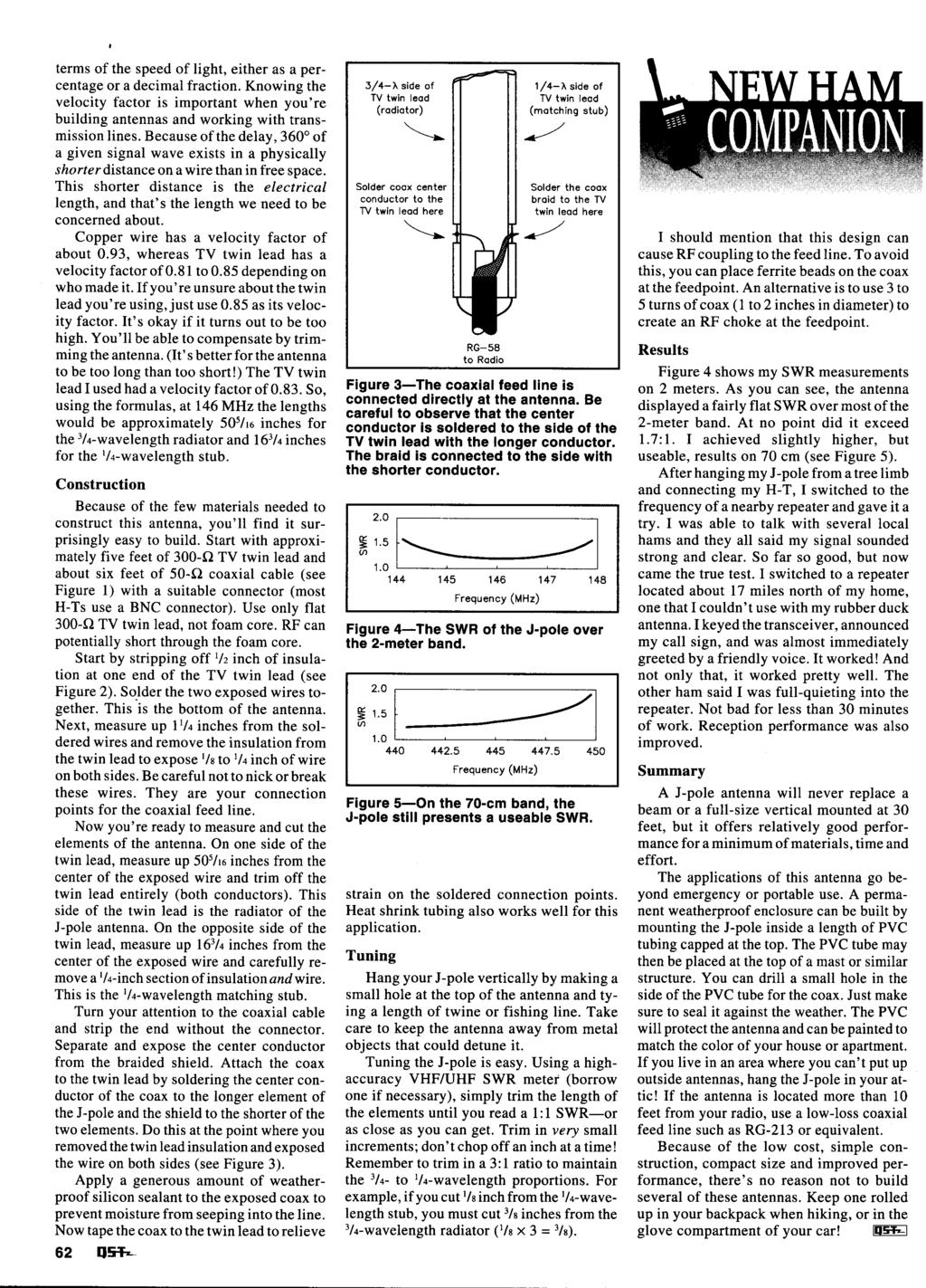
1 The DBJ-2: A Portable VHF-UHF Roll-Up J-pole Antenna for Public Service WB6IQN reviews the theory of the dual band 2 meter / 70 cm J-pole antenna and then makes detailed measurements of a practical, easy to replicate, roll-up portable antenna. Edison Fong, WB6IQN It has now been more than three years since my article on the dual band J-pole (DBJ-1) appeared in the February 2003 issue of QST. 1 I have had over 500 inquires regarding that antenna. Users have reported good results, and a few individuals even built the antenna and confirmed the reported measurements. Several major cities are using this antenna for their schools, churches and emergency operations center. When asked why they choose the DBJ-1, the most common answer was value. When budgets are tight and you want a good performance-toprice ratio, the DBJ-1 (Dual Band J-pole 1) is an excellent choice. In quantity, the materials cost about $5 per antenna and what you get is a VHF/UHF base station antenna with λ/2 vertical performance on both VHF and UHF bands. If a small city builds a dozen of these antennas for schools, public buildings, etc it would cost about $60. Not for one, but the entire dozen! Since it is constructed using PVC pipe, it is UV protected and it is waterproof. To date I have personally constructed over 400 of these antennas for various groups and individuals and have had excellent results. One has withstood harsh winter conditions in the mountains of McCall, Idaho for four years. The most common request from users is for a portable roll-up version of this antenna for backpacking or emergency use. To address this request, I will describe how the principles of the DBJ-1 can be extended to a portable roll-up antenna. Since it is the second version of this antenna, I call it the DBJ-2. Principles of the DBJ-1 The earlier DBJ-1 is based on the J-pole, 2 shown in Figure 1. Unlike the popular ground plane antenna, it doesn t need ground 1 Notes appear on page 40. From March 2007 QST ARRL Figure 1 The original 2 meter ribbon J-pole antenna. radials. The DBJ-1 is easy to construct using inexpensive materials from your local hardware store. For its simplicity and small size, the DBJ-1 offers excellent performance and consistently outperforms a ground plane antenna. Its radiation pattern is close to that of an ideal vertical dipole because it is end-fed, with virtually no distortion of the radiation pattern due to the feed line. A vertically polarized, center-fed dipole will always have some distortion of its pattern because the feed line comes out at its center, even when a balun is used. A vertically polarized, centerfed antenna is also physically more difficult to construct because of that feed line coming out horizontally from the center. The basic J-pole antenna is a half-wave vertical configuration. Unlike a vertical dipole, which because of its center feed is usually mounted alongside a tower or some kind of metal supporting structure, the radiation pattern of an end-fed J-pole mounted at the top of a tower is not distorted. The J-pole works by matching a low impedance (50 Ω) feed line to the high impedance at the end of a λ/2 vertical dipole. This is accomplished with a λ/4 matching stub shorted at one end and open at the other. The impedance repeats every λ/2, or every 360 around the Smith Chart. Between the shorted end and the high impedance end of the λ/4 shorted stub, there is a point that is close to 50 Ω and this is where the 50 Ω coax is connected. By experimenting, this point is found to be about inches from the shorted end on 2 meters. This makes intuitive sense since 50 Ω is closer to a short than to an open circuit. Although the Smith Chart shows that this point is slightly inductive, it is still an excellent match to 50 Ω coax. At resonance the SWR is below 1.2:1. Figure 1 shows the dimensions for a 2-meter J-pole. The inch λ/4 section serves as the quarter wave matching transformer. A commonly asked question is, Why inches? Isn t a λ/4 at 2 meters about inches? Yes, but twinlead has a reduced velocity factor (about 0.8) compared to air and must thus be shortened by about 20%. A conventional J-pole configuration works well because there is decoupling of the feed line from the λ/2 radiator element since the feed line is in line with the radiating λ/2 element. Thus, pattern distortion is minimized. But this only describes a single band VHF J-pole. How do we make this into a dual band J-pole? Adding a Second Band to the J-pole To incorporate UHF coverage into a VHF J-pole requires some explanation. (A more detailed explanation is given in my February 2003 QST article.) First, a 2 meter antenna does resonate at UHF. The key word here is

2 Figure 2 Elevation plane pattern comparing 2 meter J-pole on fundamental and on third harmonic frequency (70 cm), with the antenna mounted 8 feet above ground. Most of the energy at the third harmonic is launched at 44º. Figure 4 The dualband J-pole modified for portable operation thus becoming the DBJ-2. Note that the dimensions are slightly longer than those in Figure 3 because it is not enclosed in a PVC dielectric tube. Please remember that the exact dimensions vary with the manufacturer of the 300 Ω line, especially the exact tap point where the RG-174A feed coax for the radio is connected. Figure 5 The λ/4 UHF decoupling stub made of RG-174A, covered with heat shrink tubing. This is shown next to the BNC connector that goes to the transceiver. Figure 3 The original DBJ-1 dual-band J-pole. The dimensions given assume that the antenna is inserted into a 3 4 inch Class 200 PVC pipe. resonate. For example, any LC circuit can be resonant, but that does not imply that it works well as an antenna. Resonating is one thing; working well as an antenna is another. You should understand that a λ/4 146 MHz matching stub works as a 3λ/4 matching stub at 450 MHz, except for the small amount of extra transmission line losses of the extra λ/2 at UHF. The UHF signal is simply taking one more revolution around the Smith Chart. The uniqueness of the DBJ-1 concept is that it not only resonates on both bands but also actually performs as a λ/2 radiator on both bands. An interesting fact to note is that almost all antennas will resonate at their third harmonic (it will resonate on any odd harmonic 3, 5, 7, etc). This is why a 40 meter dipole can be used on 15 meters. The difference is that the performance at the third harmonic is poor when the antenna is used in a vertical configuration, as in the J pole shown in Figure 1. This can be best explained by a 19 inch 2 meter vertical over an ideal ground plane. At 2 meters, it is a λ/4 length vertical (approximately 18 inches). At UHF (450 MHz) it is a 3λ/4 vertical. Unfortunately, the additional λ/2 at UHF is out of phase with the bottom λ/4. This means cancellation occurs in the radiation pattern and the majority of the energy is launched at a takeoff angle of 45. This results in about a 4 to 6 db loss in the horizontal plane compared to a conventional λ/4 vertical placed over a ground plane. A horizontal radiation pattern obtained from EZNEC is shown in Figure 2. Notice that the 3λ/4 radiator has most of its energy at 45. Thus, although an antenna can be made to work at its third harmonic, its performance is poor. What we need is a simple, reliable method to decouple the remaining λ/2 at UHF of a 2 meter radiator, but have it remain electrically unaffected at VHF. We want independent λ/2 radiators at both VHF and UHF frequencies. The original DBJ-1 used a combination of coaxial stubs and 300 Ω twinlead cable, as shown in Figure 3. Refer to Figure 3, and start from the left hand bottom. Proceed vertically to the RG-174A lead in cable. To connect to the antenna, about 5 feet of RG-174A was used with a BNC connector on the other end. The λ/4 VHF impedance transformer is made from 300 Ω twin lead. Its approximate length is 15 inches due to the velocity factor of the 300 Ω material. The λ/4 piece is shorted at the bottom and thus is an open circuit (high impedance) at the end of the λ/4 section. This matches well to the λ/2 radiator for VHF. The 50 Ω tap is about inches from the short, as mentioned before. For UHF operation, the λ/4 matching stub at VHF is now a 3λ/4 matching stub. This is electrically a λ/4 stub with an additional λ/2 in series. Since the purpose of the matching stub is for impedance matching and not for radiation, it does not directly affect the radiation efficiency of the antenna. It does, however, suffer some transmission loss from the additional λ/2, which would not be needed if it were not for the dual band operation. I estimate this loss at about 0.1 db. Next comes the λ/2 radiating element for UHF, which is about 12 inches. To From March 2007 QST ARRL
3 Table 1 Measured Relative Performance of the Dual-band Antenna at 146 MHz VHF Flexible Standard Dual-Band VHF λ/4 GP Antenna VHF J-Pole J-Pole 4 radials 0 db 5.9 db +1.2 db +1.2 db reference Table 2 Measured Relative Performance of the Dual-band Antenna at 445 MHz UHF Fexible Standard Dual-Band UHF λ/4 GP Antenna VHF J-Pole J-Pole 4 radials 0 db 2.0 db 5.5 db 0.5 db reference make it electrically terminate at 12 inches, a λ/4 shorted stub at UHF is constructed using RG-174A. The open end is then connected to the end of the 12 inches of 300 Ω twinlead. The open circuit of this λ/4 coax is only valid at UHF. Also, notice that it is inches and not 6 inches due to the velocity factor of RG-174A, which is about 0.6. At the shorted end of the inch RG-174A is the final 18 inches of 300 Ω twinlead. Thus the 12 inches for the UHF λ/2, the inches of RG-174A for the decoupling stub at UHF, and the 18 inches of twinlead provide for the λ/2 at 2 meters. The total does not add up to a full 36 inches that you might think. This is because the λ/4 UHF RG-174A shorted stub is inductive at 2 meters, thus slightly shortening the antenna. Making it Portable The single most common question that people asked regarding the DBJ-1 is how it could be made portable. The original DBJ-1 had the antenna inserted into Class 200 PVC pipe that was 6 feet long. This was fine for fixed operation but would hardly be suitable for portable use. Basically the new antenna had to have the ability to be rolled up when not in use and had to be durable enough for use in emergency communications. The challenge was to transfer the concepts developed for the DBJ-1 and apply them to a durable roll-up portable antenna. After much thought and experimenting, I adopted the configuration shown in Figure 4. The major challenge was keeping the electrical characteristics the same as the original DBJ-1 but physically constructing it from a continuous piece of 300 Ω twinlead. Any full splices on the twinlead would compromise the durability, so to electrically disconnect sections of the twinlead, I cut small 1 4 inch notches to achieve the proper resonances. I left the insulating backbone of the 300 Ω twinlead fully intact. I determined the two notches close to the λ/4 UHF decoupling stub by experiment to give the best SWR and bandwidth. Because this antenna does not sit inside a dielectric PVC tube, the dimensions are about 5% longer than the original DBJ-1. From March 2007 QST ARRL I used heat shrink tubing to cover and protect the UHF λ/4 decoupling stub and the four 1 4 inch notches. Similarly, I protected with heat shrink tubing the RG-174A coax interface to the 300 Ω twinlead. I also attached a small Teflon tie strap to the top of the antenna so that it may be conveniently attached to a nonconductive support string. Figure 5 shows a picture of the λ/4 UHF matching stub inside the heat shrink tubing. The DBJ-2 can easily fit inside a pouch or a large pocket. It is far less complex than what would be needed for a single band ground plane, yet this antenna will consistently outperform a ground plane using 3 or 4 radials. Setup time is less than a minute. I ve constructed more than a hundred of these antennas. The top of the DBJ-2 is a high impedance point, so objects (even if they are nonmetallic) must be as far away as possible for best performance. The other sensitive points are the open end of the λ/4 VHF matching section and the open end of the λ/4 UHF decoupling stub. As with any antenna, it works best as high as possible and in the clear. To hoist the antenna, use non-conducting string. Fishing line also works well. Measured Results I measured the DBJ-2 in an open field using an Advantest R3361 Spectrum Analyzer. The results are shown in Table 1. The antenna gives a 7 db improvement over a flexible antenna at VHF. In actual practice, since the antenna can be mounted higher than the flexible antenna at the end of your handheld, results of +10 db are not uncommon. This is the electrical equivalent of giving a 4 W handheld a boost to 40 W. The DBJ-2 performs as predicted on 2 meters. It basically has the same performance as a single band J-pole, which gives about a 1 db improvement over a λ/4 ground plane antenna. There is no measurable degradation in performance by incorporating the UHF capability into a conventional J-pole. The DBJ-2 s improved performance is apparent at UHF, where it outperforms the single band 2 meter J-pole operating at UHF by about 6 db. See Table 2. This is significant. I have confidence in these measurements since the flexible antenna is about 6 db from that of the λ/4 ground plane antenna, which agrees well with the literature. Also notice that at UHF, the loss for the flex antenna is only 2.0 db, compared to the ground plane. This is because the flexible antenna at UHF is already 6 inches long, which is a quarter wave. So the major difference for the flexible antenna at UHF is the lack of ground radials. Summary I presented how to construct a portable, roll-up dual-band J-pole. I ve discussed its basic theory of operation, and have presented experimental results comparing the DBJ-2 to a standard ground plane, a traditional 2 meter J-pole and a flexible antenna. The DBJ-2 antenna is easy to construct, is low cost and is very compact. It should be an asset for ARES applications. It offers significant improvement in both the VHF and UHF bands compared to the stock flexible antenna antenna included with a handheld transceiver. If you do not have the equipment to construct or tune this antenna at both VHF and UHF, the antenna is available from the author tuned to your desired frequency. Cost is $20. him for details. Notes 1 E. Fong, The DBJ-1: A VHF-UHF Dual-Band J-Pole, QST, Feb 2003, pp J. Reynante, An Easy Dual-Band VHF/UHF Antenna, QST, Sep 1994, pp Ed Fong was first licensed in 1968 as WN6IQN. He later upgraded to Amateur Extra class with his present call of WB6IQN. He obtained BSEE and MSEE degrees from the University of California at Berkeley and his PhD from the University of San Francisco. A Senior Member of the IEEE, he has 8 patents, 24 published papers and a book in the area of communications and integrated circuit design. Presently, he is employed by the University of California at Berkeley teaching graduate classes in RF design and is a Principal Engineer at National Semiconductor, Santa Clara, California working with CMOS analog circuits. You can reach the author at edison_fong@hotmail.com.
4 Building an Emergency J-Pole By Phil Karras, KE3FL June 15, 1999 This type of J-Pole has been written about in QST, and the description has appeared elsewhere (see "Bibliography," below). The J-Pole is not difficult to make, even for a beginner. This antenna works well on 2-meters; it also works on 440 MHz. If you look at the antenna, it is a 3/4- wavelength radiating section attached to the matching stub by the shorting bar; all together it looks like the letter J, hence the name J-pole. Read all of these instructions before beginning your construction project. Nothing is more frustrating than doing something, only to find a hint afterwards that would have made the project go smoother. See below for a listing of parts and tools you'll need to make up this simple antenna. Some Past J-Pole Articles in QST: QST Jul 1995, p 62, "Build a Weatherproof PVC J-Pole Antenna," QST Jun 1995, p 71, "Try A 2-Meter Flexi-J Antenna" QST Sep 1994, p 61, "An Easy Dual-Band VHF/UHF Antenna" QST Apr 1982, p 43, (This was the article for a wire J-pole antenna I was able to find in QST). Larger picture available here. Using "ladder line" is a bit different than using solid-dielectric TV twinlead. Before cutting, stretch out the wire so that you can position the proposed cuts at a position that has a center plastic support, and not at a position that has no center plastic. This may not be possible for both the 1/4-wavelength section and the total length position. If it comes down to a choice, I recommend selecting the support at the top. This plastic melts well and can be melted back together. I have had to melt sections back together in both locations, and the antennas work just fine and hold up to field rigors.
5 Select the bottom of the antenna and strip off about 3 to 3-1/2 inches of insulation from both wires. Tack solder (temporary solder joint) a piece of wire as a shorting bar about 1 inch from the bottom of the antenna (this bar may need to be moved). To start with, the coax will be connected about 1-1/4 inch from the shorting bar. This connection and the shorting bar connection may need to be moved in order to achieve the best SWR and frequency match. Measure 17 inches up from the shorting bar on one end only and cut a 1/4-inch gap in the wire at this position. (You can melt the plastic back together at this location if needed.) Now measure 52-1/4 inches up from the shorting bar. If this location has no center plastic support, try to remove as little insulation as needed in order to get at the wire and snip it. Cut out at least one inch of wire, then melt the plastic back onto the locations where you removed it. I use a sharp knife to cut into the insulation and not into the wire. Then I pry the wire out with a pin and snip it or solder it at the correct location. Preparing the Coax Bend the coax about an inch from the end, and score the insulation with a sharp knife. This cuts into the insulation without damaging the shield if done gently. Then rotate the coax so you can continue scoring the coax until it is cut all the way around. Cut the insulation from the new cut, up to the end of the coax. You should now be able to pull off the insulation with pliers. Remember to always cut away from yourself! Never use wire strippers on the large portion of the coax; it only damages the shield. If you have a tool designed for coax, use it. Prepare the antenna end of the coax: Separate the coax shield and twist it together. Strip off about 3/4-inch of insulation from the center conductor of the coax. (Do not solder at this time.) You'll install the appropriate connector (BNC, PL-259) at the other end of the coax. Follow the installation directions that come with the connector, or consult The ARRL Handbook for more information. Connecting Coax to Antenna Wrap the shield 1-1/4 inch up from the shorting bar around the 17-inch side of the twin lead. Wrap it in such a way that the distance from the coax to the shorting bar is the same for both the shield and the center conductor. Solder the shield to the twin lead. Wrap the center coax conductor around the longer twin lead wire up from the shorting bar (the same distance that the shield is wrapped to the other wire) and solder it. Cut off the excess coax wire. Also, cut off all the excess twin lead at the top except for a loop or two. These ladder steps are great for hanging the antenna over a nail or hook, so leave at least one of them.
6 Your antenna is now ready to test. Testing Your J-Pole Get your VHF SWR analyzer or meter. Hang the antenna away from all objects (I hang mine from the top of a window and this seems to work almost as well as from a tree). For best SWR measurements, the antenna should be at least 2 wavelengths away from any object. (For 2-meters this is approximately 13 feet.) Set your radio for lowest power and MHz simplex. Test out the antenna for and as well. If all three are below 1.7 SWR and the SWR for 146 is about 1.3 or lower, you are done. If not, see for the sidebar "Help for Lowering the SWR, Changing the Frequency, and Increasing the Bandwidth" below. Once you are done, slip the shrink tubing onto the antenna over the coax connections, squirt some electrical-connection safe RTV into the bottom of the shrink tubing, and then heat up the tubing from the bottom up. This should push (squeeze) some RTV all the way to the top of the shrink tubing. Wipe off the excess and hang the antenna for 12 to 24 hours to let the RTV dry. The SWR at should be close to and below 1.3 to 1; for and 148.0, it should be 1.7 to 1 or lower. If you have difficulty obtaining these results, see "Help for Lowering the SWR, Changing the Frequency, and Increasing the Bandwidth", below. At MHz, the antenna should read below 1.5 to 1. I have not checked it out as thoroughly as I have 2 meters, but I do know that it is not a nice one-dip curve; rather, it is a multiple dip/peak curve. Editor's note: Philip Karras, KE3FL, lives in Mt Airy, Maryland. An ARRL Life Member, he holds a field appointment as Assistant Emergency Coordinator in Carroll County, Maryland. He's also an OES, ORS, and a volunteer examiner. He may be contacted via to ke3fl@arrl.net. Visit his Web site at PARTS LIST: 5 feet of 450-ohm ladder line 20 feet of RG-58 or similar coax 2 inches of heat-shrinkable tubing NECESSARY TOOLS: Soldering iron (20-30 W) Solder Wire cutters Wire strippers VHF SWR meter or antenna analyzer Sharp knife Pliers RTV silicone sealant Heat gun or hair dryer (for heat-shrinkable tubing)
7 Help for Lowering the SWR, Changing the Frequency, and Increasing the Bandwidth If your antenna did not have a nice low SWR at the desired center frequency, try moving the shorting bar down about 0.1 inch at a time until you get the lowest SWR you can--even if this is nowhere close to 1:1. You may have to move it back up if you go too far. Normally I find that I have to move the shorting bar down, ie, away from the feed-point, but it's always possible that it will need to go the other way too. If you have already cut the extra wire off the bottom of the antenna, you will need to add some back if moving the shorting bar closer to the feed-point only makes the SWR worse. Add about two inches to both the matching stub and radiator at the bottom of the antenna. Once the position of the shorting bar to the feed point that produces the lowest SWR has been found, move the coax contact points and the shorting bar together until you can get this lowest SWR match at the desired frequency. The important point to remember here is that the distance between the feed-point and the shorting bar determines the lowest SWR. This distance must not change while trying to get the lowest SWR at the desired center frequency. If the lowest SWR you can get by moving the shorting is not 1:1, it will turn out to be closer to 1:1 once you move both the shorting bar and the coax feed point so that the lowest SWR is at the desired center frequency. Help on Shifting the Frequency If you need to shift the frequency and moving the tap point doesn't change it enough, you can cut the J-Pole. You should not have to do this for this antenna since the dimensions for this antenna have been worked out over years of experience by many different people. Here are the two rules of thumb for changing the center frequency of any antenna: LLL: Longer antenna = Longer wavelength = Lower frequency SSH: Shorter antenna = Shorter wavelength = Higher frequency When cutting the antenna shorter, I recommend making only one-half the change you calculate. In this way you may be able to prevent making too large a cut and having to undo it. All changes are interactive, some more so than others, but expect to see SWR changes for length changes, and frequency shifts when moving the shorting bar/feed-point up and down. (Remember to move both the feed-point and the shorting bar in tandem, keeping the distance between them constant when trying to re-center the lowest SWR at the frequency you want.) Help on Increasing the Bandwidth (BW) Once again you should not ever have this problem with the 2-meter J-pole since the dimensions have been worked out by calculation and by trial and error by many people. However, if you are trying to design for a new frequency, you might need to be able to change the BW. A very narrow BW may be an indication that the radiator is too long, or it is too long in relation to the matching stub. I have only performed one experiment so far. In this experiment I added
8 one inch of wire to the top of a good working J-pole antenna for 2-meters. The bandwidth dropped to about 0.6 MHz. When I removed the extra wire, the BW returned to about 3.8 MHz between 1.7:1 SWR points. Other things I've tried made such small changes in the bandwidth that I was never sure the data was significant. Was the change due to the method tried or did I do something else a bit differently that caused the change?

9
10
11 Q: I built the dual-band J-pole antenna from the article in the September 1994 New Ham Companion ( An Easy Dual-Band VHF/UHF Antenna, page 61), but I just can t get it to work. What can I do? A: Try adding a balun to the coax. A balun is necessary because a J-pole antenna uses a balanced feed (the 1/4-wavelength matching section) connected to an unbalanced feed line (the coax). The simplest way to make a balun is to get a split-core cylindrical ferrite (such as an Amidon 2X ) and attach it to the outside of the coax 1/4 wavelength from the feedpoint. On VHF frequencies some ferrite materials are not effective, so be sure to get type 43 material for best results. Another thing you may want to do is lengthen the antenna a bit. The formula for the antenna length in the article is unintentionally misleading. Because the 1/2-wavelength radiator is not a feed line, it has a much higher velocity factor than that of twin lead. The velocity factor of copper wire is about 0.95, so the 1/2-wave radiator section should be 38-3/8 inches long.

12 VK5AH 4 Bander Page 8 of 9 10/16/2007 Back to Contents
The DBJ-1: A VHF-UHF Dual-Band J-Pole
 By Edison Fong, WB6IQN The DBJ-1: A VHF-UHF Dual-Band J-Pole Searching for an inexpensive, high-performance dual-band base antenna for VHF and UHF? Build a simple antenna that uses a single feed line for
VHF/UHF Dual Band J-Pole. By: Ed Fong WB6IQN
 VHF/UHF Dual Band J-Pole By: Ed Fong WB6IQN email: edison_fong@hotmail.com ARRL VHF/UHF Antenna Classics ARRL Vol. 8 Antenna Compendium ARRL Vol. 3 Antenna Compendium QST March 2007 QST February 2003 QST
A Tri Band Antenna for 2 meters, 220 MHz, and 70cm Antenna Without Radials. By: Edison Fong (WB6IQN)
") A Tri Band Antenna for 2 meters, 220 MHz, and 70cm Antenna Without Radials By: Edison Fong (WB6IQN) Twenty years ago a single band handie talkie would have been adequate for emergency use since almost
A Tri Band Antenna for 2 meters, 220 MHz, and 70cm Antenna Without Radials By: Edison Fong (WB6IQN) Twenty years ago a single band handie talkie would have been adequate for emergency use since almost
MFJ-219/219N 440 MHz UHF SWR Analyzer TABLE OF CONTENTS
 MFJ-219/219N 440 MHz UHF SWR Analyzer TABLE OF CONTENTS Introduction...2 Powering The MFJ-219/219N...3 Battery Installation...3 Operation Of The MFJ-219/219N...4 SWR and the MFJ-219/219N...4 Measuring
Antenna Design for FM-02
 Antenna Design for FM-02 I recently received my FM-02 FM transmitter which I purchased from WLC. I researched the forum on what antennas where being used by the DIY community and found a nice write-up
Technician License. Course
 Technician License Course Technician License Course Chapter 4 Lesson Plan Module - 10 Practical Antennas The Dipole Most basic antenna The Dipole Most basic antenna The Dipole Total length is ½ wavelength
TWO METER HOMEMADE SLIM JIM ANTENNA
 Gordon Gibby July 15, 2016 TWO METER HOMEMADE SLIM JIM ANTENNA WIRE: Start with a piece of solid #14 AWG household wire approximately 3 yards and 9 inches long (117 ) (It is easier to be a couple inches
Optimizing Your Stations Performance
 Optimizing Your Stations Performance A few hints / techniques, recommendations for getting the most RF out to the Antenna from your HF, VHF / UHF station. Tonights Presenters: Doug Theriault NO1D John
Portable or Emergency VHF Antennas Paul R. Jorgenson KE7HR
 For emergency or public service events it is often necessary to have more antenna than the rubber duck on your handheld VHF radio. Nearly ANY external antenna will provide more coverage for your handheld
4 Antennas as an essential part of any radio station
 4 Antennas as an essential part of any radio station 4.1 Choosing an antenna Communicators quickly learn two antenna truths: Any antenna is better than no antenna. Time, effort and money invested in the
The J-Pole Antenna. Gary Wescom
 The J-Pole Antenna Gary Wescom - 2018 Much has been written about the J-Pole antenna. A simple Google search will net days worth of reading material on the subject. That would tend to indicate this paper
Chapter 6 Antenna Basics. Dipoles, Ground-planes, and Wires Directional Antennas Feed Lines
 Chapter 6 Antenna Basics Dipoles, Ground-planes, and Wires Directional Antennas Feed Lines Some General Rules Bigger is better. (Most of the time) Higher is better. (Most of the time) Lower SWR is better.
L. B. Cebik, W4RNL. Basic Transmission Line Properties
 L. B. Cebik, W4RNL In the course of developing this collection of notes, I have had occasion to use and to refer to both series and parallel coaxial cable assemblies. Perhaps a few notes specifically devoted
Cray Valley Radio Society. Real Life Wire Antennas
 Cray Valley Radio Society Real Life Wire Antennas 1 The basic dipole The size of an antenna is determined by the wavelength of operation In free space: ~3x10 8 m/s Frequency x Wavelength = Speed of Light,
Technician Licensing Class. Antennas
 Technician Licensing Class Antennas Antennas A simple dipole mounted so the conductor is parallel to the Earth's surface is a horizontally polarized antenna. T9A3 Polarization is referenced to the Earth
Technician Licensing Class T9
 Technician Licensing Class T9 Amateur Radio Course Monroe EMS Building Monroe, Utah January 11/18, 2014 January 22, 2014 Testing Session Valid dates: July 1, 2010 June 30, 2014 Amateur Radio Technician
Page 1The VersaTee Vertical 60m, 80m Modular Antenna System Tutorial Manual
 Page 1The VersaTee Vertical 60m, 80m Modular Antenna System Tutorial Manual by: Lou Rummel, KE4UYP Page 1 In the world of low band antennas this antenna design is unique in many different ways. 1. It is
The Fabulous Dipole. Ham Radio s Most Versatile Antenna
 The Fabulous Dipole Ham Radio s Most Versatile Antenna 1 What is a Dipole? Gets its name from its two halves One leg on each side of center Each leg is the same length It s a balanced antenna The voltages
Technician License Course Chapter 4. Lesson Plan Module 10 Practical Antennas
 Technician License Course Chapter 4 Lesson Plan Module 10 Practical Antennas The Dipole Most basic antenna Total length is ½ wavelength (½ λ) Usual construction: Two equal halves of wire, rod, or tubing
A short, off-center fed dipole for 40 m and 20 m by Daniel Marks, KW4TI
 A short, off-center fed dipole for 40 m and 20 m by Daniel Marks, KW4TI Version 2017-Nov-7 Abstract: This antenna is a 20 to 25 foot long (6.0 m to 7.6 m) off-center fed dipole antenna for the 20 m and
Pacific Antenna 20 and 40M Lightweight Dipole Kit
 Pacific Antenna 20 and 40M Lightweight Dipole Kit Antenna diagram showing configuration and lengths when assembled 7 8 16 9 16 9 Description The Pacific Antenna lightweight dual band dipole kit provides
4/25/2012. Supplement T9. 2 Exam Questions, 2 Groups. Amateur Radio Technician Class T9A: T9A: T9A: T9A:
 Amateur Radio Technician Class Element 2 Course Presentation ti ELEMENT 2 SUB-ELEMENTS Technician Licensing Class Supplement T9 Antennas, Feedlines 2 Exam Questions, 2 Groups T1 - FCC Rules, descriptions
Basic Wire Antennas. Part II: Loops and Verticals
 Basic Wire Antennas Part II: Loops and Verticals A loop antenna is composed of a single loop of wire, greater than a half wavelength long. The loop does not have to be any particular shape. RF power can
FCC Technician License Course
 FCC Technician License Course 2014-2018 FCC Element 2 Technician Class Question Pool Presented by: Tamiami Amateur Radio Club (TARC) WELCOME To the third of 4, 3-hour classes presented by TARC to prepare
Milton Keynes Amateur Radio Society (MKARS)
") Milton Keynes Amateur Radio Society (MKARS) Intermediate Licence Course Feeders Antennas Matching (Worksheets 31, 32 & 33) MKARS Intermediate Licence Course - Worksheet 31 32 33 Antennas Feeders Matching
Milton Keynes Amateur Radio Society (MKARS) Intermediate Licence Course Feeders Antennas Matching (Worksheets 31, 32 & 33) MKARS Intermediate Licence Course - Worksheet 31 32 33 Antennas Feeders Matching
Least understood topics by most HAMs RF Safety Ground Antennas Matching & Feed Lines
 Least understood topics by most HAMs RF Safety Ground Antennas Matching & Feed Lines Remember this question from the General License Exam? G0A03 (D) How can you determine that your station complies with
4/29/2012. General Class Element 3 Course Presentation. Ant Antennas as. Subelement G9. 4 Exam Questions, 4 Groups
 General Class Element 3 Course Presentation ti ELEMENT 3 SUB ELEMENTS General Licensing Class Subelement G9 Antennas and Feedlines 4 Exam Questions, 4 Groups G1 Commission s Rules G2 Operating Procedures
Pacific Antenna 20 and 40M Lightweight Dipole Kit
 Pacific Antenna 20 and 40M Lightweight Dipole Kit Diagram showing configuration and approximate lengths 8 3 16 9 16 9 8 3 Description The Pacific Antenna lightweight dual band, trap dipole kit provides
MAGNETIC LOOP SYSTEMS SIMPLIFIED
 MAGNETIC LOOP SYSTEMS SIMPLIFIED By Lez Morrison VK2SON Many articles have been published and made available on websites recently. Unfortunately they have tended to make construction sound complicated
HFp. User s Guide. Vertical. entenna. 7 MHz 30 MHz Amateur Radio Antenna Plus 6-Meters
 User s Guide HFp Vertical 7 MHz 30 MHz Amateur Radio Antenna Plus 6-Meters The Ventenna Co. LLC P.O. Box 2998, Citrus Heights, CA, 956 www.ventenna.com entenna Table of Contents The HFp Antenna -------------------------------------------------------------------
BUILD A HIGH PERFORMANCE TWO ELEMENT TRI-BAND CUBICAL QUAD. By Bob Rosier K4OCE INTRODUCTION THEORY AND GENERAL INFORMATION
 BUILD A HIGH PERFORMANCE TWO ELEMENT TRI-BAND CUBICAL QUAD INTRODUCTION By Bob Rosier K4OCE Lots of DX can be worked with a dipole at the QRP level, however, a beam will obviously give you additional gain
The W3FF Portable Dipole
 The W3FF Portable Dipole This is the antenna I designed for my 'walking portable' station. It is a dipole constructed out of the plastic plumbing pipe CPVC. There are telescoping whips at the ends of each
High Performance 40 Meters Vertical Without Radials
 High Performance 40 Meters Vertical Without Radials This shortened easy-to-build vertical, with no-radials, is made from surplus military camouflage poles. It has gain and wave angle comparable to a full-sized
Emergency Antennas. Presented by Ham Hilliard W4GMM
 Emergency Antennas Presented by Ham Hilliard W4GMM Dipole antenna Vertical antenna Random wire antenna Dipole antenna The half wave dipole antenna consists of a conductive wire or rod that is half the
PAC-12 Kit Contents. Tools Needed Soldering iron Phillips screwdriver Wire stripper Wrenches, 7/16 and 1/2 Terminal crimp tool Pliers Solder
 PAC-2 Kit Contents Part Quantity Screws: 8/32 x 3/8 Screws: 8-32 x 5/6 Screw: 8-32 x /4 #8 internal tooth washers #8 solder lug ring terminals Bolt: Aluminum, /4-20 x.5 /4 internal tooth washer Nut: Aluminum
The EMCOMM Easytenna
 The EMCOMM Easytenna This document will detail how to build an easy to install multiband dipole type antenna for emergency communications using the NVIS propagation mode. History The NVIS mode is one in
J-Poles. Mythbusting J-Pole Antennas
 Mythbusting J-Pole Antennas For an antenna to work correctly, it must do two things well 1) Accept power from the feed line impedance match, SWR (ideally) 1:1 2) Radiate power in a pattern that is useful
MFJ-249B HF/VHF SWR ANALYZER
 TABLE OF CONTENTS MFJ-249B... 2 Introduction... 2 Powering The MFJ-249B... 3 Battery Installation... 3 Alkaline Batteries... 3 NiCd Batteries... 4 Power Saving Mode... 4 Operation Of The MFJ-249B...5 SWR
Some hints/tips on how to assemble nice COAX TRAPS!
 Some hints/tips on how to assemble nice COAX TRAPS! Before we start to assemble our traps, here some general info as introduction : Coax traps are cheap, easy to assemble in a reproducible manner, very
July 1995 QST Volume 79, Number 7
 Lab Notes Prepared by the ARRL Laboratory Staff (e-mail: tis@arrl.org) By Mike Tracy, KC1SX Technical Information Service Coordinator Q: I m just getting started on VHF and UHF FM and I want to set up
1) Transmission Line Transformer a. First appeared on the scene in 1944 in a paper by George Guanella as a transmission line transformer, the 1:1
 Transmission Line Transformer a. First appeared on the scene in 1944 in a paper by George Guanella as a transmission line transformer, the 1:1") 1) Transmission Line Transformer a. First appeared on the scene in 1944 in a paper by George Guanella as a transmission line transformer, the 1:1 Guanella Balun is the basic building Balun building block.
1) Transmission Line Transformer a. First appeared on the scene in 1944 in a paper by George Guanella as a transmission line transformer, the 1:1 Guanella Balun is the basic building Balun building block.
THE W3FF HOMEBREW BUDDIPOLE
 THE W3FF HOMEBREW BUDDIPOLE A PORTABLE ANTENNA DESIGN FOR AMATEUR RADIO History of the Buddipole In January of 2000, I began experimenting with a walking portable ham station. Since then, thousands of
General License Class Chapter 6 - Antennas. Bob KA9BHD Eric K9VIC
 General License Class Chapter 6 - Antennas Bob KA9BHD Eric K9VIC Learning Objectives Teach you enough to get all the antenna questions right during the VE Session Learn a few things from you about antennas
The first thing to realize is that there are two types of baluns: Current Baluns and Voltage Baluns.
 Choosing the Correct Balun By Tom, W8JI General Info on Baluns Balun is an acronym for BALanced to UNbalanced, which describes certain circuit behavior in a transmission line, source or load. Most communications
Feed Line Currents for Neophytes.
 Feed Line Currents for Neophytes. This paper discusses the sources of feed line currents and the methods used to control them. During the course of this paper two sources of feed line currents are discussed:
6M HALO VERSON II + OPTIONAL 2M GROUND PLANE
 The halo is an omnidirectional, horizontally polarized antenna with about the same gain as a dipole but without the low elevation nulls off the ends (+5.5 to +3.5dBi variation for the Halo vs. +7.9 to
Plotting all this data got old using a chart to look up VSWR each time. Here is a formula I found rooting around the web. Let Excel do the work
 My compliments to John, K5GD for heading up the antenna building sessions, and thanks to Ron, N5QV for providing the antenna comparison data. I wanted to share my experience with this project. First of
The design of Ruthroff broadband voltage transformers M. Ehrenfried G8JNJ
 The design of Ruthroff broadband voltage transformers M. Ehrenfried G8JNJ Introduction I started investigating balun construction as a result of various observations I made whilst building HF antennas.
Pacific Antenna 20 and 40M Lightweight Dipole Kit
 Pacific Antenna 20 and 40M Lightweight Dipole Kit Diagram showing configuration and approximate lengths 8 6 16 9 16 9 8 6 Description The Pacific Antenna lightweight dual band, trap dipole kit provides
Technician License Course Chapter 4. Lesson Plan Module 9 Antenna Fundamentals, Feed Lines & SWR
 Technician License Course Chapter 4 Lesson Plan Module 9 Antenna Fundamentals, Feed Lines & SWR The Antenna System Antenna: Transforms current into radio waves (transmit) and vice versa (receive). Feed
End Fed Half Wave Antenna Coupler
 End Fed Half Wave Antenna Coupler The finished End Fed Half Wave antenna coupler. Centre fed half wave dipoles make great, simple and effective antennas for the HF bands. Sometimes however, the centre
COAXIAL TRANSMISSION LINE COMMON-MODE CURRENT
 COAXIAL TRANSMISSION LINE COMMON-MODE CURRENT Introduction Coaxial transmission lines are popular for their wide frequency bandwidth and high resistance to electromagnetic interference (EMI). Coax cables
TZ-RD-1740 Rotary Dipole Instruction Manual
 TZ-RD-1740 17/40m Rotary Dipole Instruction Manual The TZ-RD-1740 is a loaded dipole antenna for the 40m band and a full size rotary dipole for the 17m band. The antenna uses an aluminium radiating section
Coming next: Wireless antennas for beginners
 Coming next: Wireless antennas for beginners In other rooms: Logbook of the World (Sussex Suite) SO2R contest operation (Stable Suite) Wires for your wireless: Simple wire antennas for beginners dominic
Adjust Antenna Tuners Antenna Measurements Capacitor Measurement Measure Feed Point Impedance Measure Ground Loss Inductor Measurement
 The Micro908 antenna analyzer is an extremely useful instrument to have around the ham shack or homebrewer s workbench. This section describes the basic uses, as well as some advanced techniques for which
INSTRUCTION MANUAL. Specifications Electrical. Front-To-Back Ratio VSWR at Resonance Less than 1.5:1 Nominal Impedance. Mechanical
 300 Industrial Park Road, Starkville, MS 39759 Ph: (662) 323-8538 FAX: (662) 323-6551 TH-3JRS Tri-band HF 3 Elements Beam Covers 10, 15 and 20 Meters INSTRUCTION MANUAL WARNING Installation of this product
SOME USES FOR RF1,RF5 and VA1 ANALYSTS. SWR Measurement
 SOME USES FOR RF1,RF5 and VA1 ANALYSTS THE HANDIEST INSTRUMENTS IN DECADES! When you put up an antenna in the the old days, it could be a real struggle. The only way to tell if it was tuned to the right
Table of Contents. MFJ-1778 G5RV Multiband Antenna
 Table of Contents MFJ-1778 G5RV Multiband Antenna Introduction... 1 Theory Of Operation... 1 80 meter band:... 1 40 meter band:... 1 30 meter band:... 2 20 meter band:... 2 17 meter band:... 2 15 meter
Last year I described several Low Band RX antennas that would enable you to hear DX stations on 160, 80 and 40M. This will show you how to build
 Last year I described several Low Band RX antennas that would enable you to hear DX stations on 160, 80 and 40M. This will show you how to build transmit antennas that will help you break the pileups!
Newcomers And Elmers Net: Wire Antennas Robert AK3Q
 Newcomers And Elmers Net: Wire Antennas 02-07-16 Robert AK3Q Wire antennas represent one of the greatest values in the radio hobby world. For less than the cost of a good meal out on the town you can buy
Beams and Directional Antennas
 Beams and Directional Antennas The Horizontal Dipole Our discussion in this chapter is about the more conventional horizontal dipole and the simplified theory behind dipole based designs. For clarity,
A IVE-BAND, TWO-ELEMENT H QUAD
 A IVE-BAND, TWO-ELEMENT H QUAD Two quad designs are described in this article, both nearly identical. One was constructed by KC6T from scratch, and the other was built by Al Doig, W6NBH, using modified
WCARES NEEDS YOU! CONSIDER MAKING A TECHNICAL PRESENTATION AT AN UPCOMING CHEW & CHAT MEETING LEARN SOMETHING NEW AND PRESENT
 WCARES NEEDS YOU! CONSIDER MAKING A TECHNICAL PRESENTATION AT AN UPCOMING CHEW & CHAT MEETING SHARE WHAT YOU KNOW LEARN SOMETHING NEW AND PRESENT IT CONTACT TIM AD4CJ AD4CJ@arrl.net 1 Transmission Line
Amateur Extra Manual Chapter 9.4 Transmission Lines
 9.4 TRANSMISSION LINES (page 9-31) WAVELENGTH IN A FEED LINE (page 9-31) VELOCITY OF PROPAGATION (page 9-32) Speed of Wave in a Transmission Line VF = Velocity Factor = Speed of Light in a Vacuum Question
Nick Garner N3WG and George Zafiropoulos KJ6VU
 Nick Garner N3WG and George Zafiropoulos KJ6VU Introduction Over the last few years, there has been a significant increase in the number of radio amateurs interested in portable operating. This is due
Antennas Demystified Antennas in Emergency Communications. Scott Honaker N7SS
 Antennas Demystified Antennas in Emergency Communications Scott Honaker N7SS Importance of Antennas Antennas are more important than the radio A $5000 TV with rabbit ears will have a lousy picture Antennas
Antennas and Propagation Chapters T4, G7, G8 Antenna Fundamentals, More Antenna Types, Feed lines and Measurements, Propagation
 Antennas and Propagation Chapters T4, G7, G8 Antenna Fundamentals, More Antenna Types, Feed lines and Measurements, Propagation =============================================================== Antenna Fundamentals
Technician License. Course
 Technician License Course Technician License Course Chapter 4 Lesson Plan Module - 9 Antenna Fundamentals Feed Lines & SWR The Antenna System The Antenna System Antenna: Transforms current into radio waves
HFp. User s Guide. Vertical. entenna. 7 MHz 54 MHz Amateur Radio Antenna. The Ventenna Co. LLC P.O. Box 227 Huston, ID
 User s Guide HFp Vertical 7 MHz 54 MHz Amateur Radio Antenna The Ventenna Co. LLC P.O. Box 227 Huston, ID 83630 www.ventenna.com entenna Table of Contents The HFp Antenna -------------------------------------------------------------------
2m 70cm Dual Band High Performance Gain Base Station Antenna
 2m 70cm Dual Band High Performance Gain Base Station Antenna We have made it easy for you to find a PDF Ebooks without any digging. And by having access to our ebooks online or by storing it on your computer,
CHAPTER 5 PRINTED FLARED DIPOLE ANTENNA
 CHAPTER 5 PRINTED FLARED DIPOLE ANTENNA 5.1 INTRODUCTION This chapter deals with the design of L-band printed dipole antenna (operating frequency of 1060 MHz). A study is carried out to obtain 40 % impedance
WRAPS Rotor Enhancements Add a Second Beam and Circular Polarization
 WRAPS Rotor Enhancements Add a Second Beam and Circular Polarization Mark Spencer, WA8SME (mspencer@arrl.org) ARRL Education and Technology Program Part 1: Tricked-Out WRAPS Satellite Antenna Rotator Adds
Wire Antennas For Limited Space
 Wire Antennas For Limited Space Jim Brown K9YC Santa Cruz, CA http://audiosystemsgroup.com Our Objectives Good Antennas Good efficiency Good predictable patterns Minimal noise pickup and RFI Inexpensive
A Folding 5-Element Yagi for 144 MHz
 A Folding 5-Element Yagi for 144 MHz Steve Kavanagh, VE3SMA, April 2017 1. Introduction I have found antennas which fold up quickly to take less space in the car to be useful in VHF/UHF portable operating.
THE VK WINDOM. Seemed Like a Good Idea
 THE VK WINDOM Seemed Like a Good Idea Over the years there have been many articles about the Windom antenna. It was first popularized by a US amateur called Windom whose 40 m signal on this antenna was
How to use your antenna tuner.
 How to use your antenna tuner. There's more to it than what is in your manual or on most how to do it websites! http://www.arrl.org/tis/info/ant-tuner-op.html Here is a neat site with a "T" network simulator.
RX Directional Antennas. Detuning of TX Antennas.
 1. Models Impact of Resonant TX antennas on the Radiation Pattern of RX Directional Antennas. Detuning of TX Antennas. Chavdar Levkov, lz1aq@abv.bg, www.lz1aq.signacor.com 2-element small loops and 2-element
Model S9v. 43 Multiband Vertical Antenna Installation Guide
 Model S9v 43 Multiband Vertical Antenna Installation Guide. WARNING: INSTALLATION OF THIS PRODUCT NEAR POWERLINES IS DANGEROUS. FOR YOUR SAFETY, FOLLOW THE INSTALLATION DIRECTIONS. INTRODUCTION Thank you
One I had narrowed the options down, I installed some wire and started testing.
 Loft & Attic antennas for restricted spaces - M. Ehrenfried G8JNJ I ve recently been looking at designs for an efficient antenna that would fit in a loft. I hoped to find something that would work on with
ANTENNAS. I will mostly be talking about transmission. Keep in mind though, whatever is said about transmission is true of reception.
 Reading 37 Ron Bertrand VK2DQ http://www.radioelectronicschool.com ANTENNAS The purpose of an antenna is to receive and/or transmit electromagnetic radiation. When the antenna is not connected directly
A Transmatch for Balanced or Unbalanced Lines
 A Transmatch for Balanced or Unbalanced Lines Most modern transmitters are designed to operate into loads of approximately 50 Ω. Solid-state transmitters produce progressively lower output power as the
Chapter 5.0 Antennas Section 5.1 Theory & Principles
 Chapter 5.0 Antennas Section 5.1 Theory & Principles G3C11 (B) p.135 Which of the following antenna types will be most effective for skip communications on 40-meters during the day? A. A vertical antenna
Hardware Store 40m Magnetic Loop Antenna for Regional and EMCOM Use. Richard Bono NO5V. QST Antenna Design Competition 80 through 10 meter entry
 Hardware Store 40m Magnetic Loop Antenna for Regional and EMCOM Use Richard Bono NO5V QST Antenna Design Competition 80 through 10 meter entry Overview: This describes a field deployable magnetic loop
High-Power Directional Couplers with Excellent Performance That You Can Build
 High-Power Directional Couplers with Excellent Performance That You Can Build Paul Wade W1GHZ 2010 w1ghz@arrl.net A directional coupler is used to sample the RF energy travelling in a transmission line
DO NOT COPY. Basic HF Antennas. Bill Shanney, W6QR
 Basic HF Antennas Bill Shanney, W6QR When I was first licensed in 1961 I didn t know much about antennas. I put up the longest wire that fit on my parent s lot at the lofty height of 25 and fed it with
The Coaxial Trap Confusion (mostly resolved?)
") The Coaxial Trap Confusion (mostly resolved?) Background Antenna traps need an inductor and a capacitor in a parallel circuit to effectively cut off the end of the antenna for some higher frequency giving
The Coaxial Trap Confusion (mostly resolved?) Background Antenna traps need an inductor and a capacitor in a parallel circuit to effectively cut off the end of the antenna for some higher frequency giving
MFJ Manual Loop Tuner Considerations
 Pagina 1 0 items Proceed to Secure Checkout All Categories Accessories Analyzers Products Tuners Morse Code / CW Power Supplies Product Search Search! List All Products Site Menu Customer Account Order
VHF and UHF Antennas for QRP Portable Operation. Prepared for the QRP forum at Pacificon2011 by KK6MC James Duffey October 15, 2011
 VHF and UHF Antennas for QRP Portable Operation Prepared for the QRP forum at Pacificon2011 by KK6MC James Duffey October 15, 2011 Overview Get on the air from portable locations with simple and effective
Technician Licensing Class. Lesson 4. presented by the Arlington Radio Public Service Club Arlington County, Virginia
 Technician Licensing Class Lesson 4 presented by the Arlington Radio Public Service Club Arlington County, Virginia 1 Quiz Sub elements T6 & T7 2 Good Engineering Practice Sub element T8 3 A Basic Station
Installation Instructions Hustler 6-BTV Trap Vertical
 Installation Instructions Hustler 6-BTV Trap Vertical ASSEMBLY 1. Check the package contents against the parts list on page 2. 2. WARNING. Installation of this product near power lines is dangerous. For
A Folding 11-Element Yagi for 432 MHz
 A Folding 11-Element Yagi for 432 MHz Steve Kavanagh, VE3SMA, October 2015 1. Introduction For portable VHF/UHF operation I have found it convenient at times to have some antennas which fold up quickly
Build a 12/17 Meter Trap Dipole Phil Salas AD5X
 Build a 12/17 Meter Trap Dipole Phil Salas AD5X Introduction Why a 12/17 meter rotatable dipole? Well, many folks have verticals for the lower bands, and multi-band dipoles or beams for 20-, 15-, and 10
A Triangle for the Short Vertical
 1 von 11 03.03.2015 12:37 A Triangle for the Short Vertical Operator L. B. Cebik, W4RNL Last month, I described a triangle array of three full-size vertical dipoles for 40 meters (with 30 meters as a bonus).
MFJ-1762 Instruction Manual
 MFJ-1762 Instruction Manual INTRODUCTION Thank you for purchasing the MFJ-1762 three-element six-meter Yagi. The MFJ-1762 is a light-weight directional antenna especially designed for installation with
ANTENNAS Wires, Verticals and Arrays
 ANTENNAS Wires, Verticals and Arrays Presented by Pete Rimmel N8PR 2 1 Tonight we are going to talk about antennas. Anything that will conduct electricity can be made to radiate RF can be called an antenna.
Coaxial Cable Feeder Influence on Four Stacked Yagi Antennas Array Dragoslav Dobričić, YU1AW
 Coaxial Cable Feeder Influence on Four Stacked Yagi Antennas Array Dragoslav Dobričić, YU1AW dragan@antennex.com Introduction Aprevious article series consisted of two parts [1, 2] showing the results
CHAPTER 8 ANTENNAS 1
 CHAPTER 8 ANTENNAS 1 2 Antennas A good antenna works A bad antenna is a waste of time & money Antenna systems can be very inexpensive and simple They can also be very expensive 3 Antenna Considerations
Half-Wave Dipole. Radiation Resistance. Antenna Efficiency
 Antennas Simple Antennas Isotropic radiator is the simplest antenna mathematically Radiates all the power supplied to it, equally in all directions Theoretical only, can t be built Useful as a reference:
Using Ferrite Beads Keep RF Out of TV Sets, Telephones, VCR's Burglar Alarms and other Electronic Equipment
 Using Ferrite Beads Keep RF Out of TV Sets, Telephones, VCR's Burglar Alarms and other Electronic Equipment RFI and TVI have been with us for a long time. Now we have microwave ovens, VCR's and many other
SWL Receiving Antenna Experiments
 SWL Receiving Antenna Experiments Introduction I have a lot to learn about SWL antennas. What follows are some brief experiments I performed in late October 2005. I have been experimenting with a half