VHF/UHF Dual Band J-Pole. By: Ed Fong WB6IQN
|
|
|
- John McGee
- 5 years ago
- Views:
Transcription
1 VHF/UHF Dual Band J-Pole By: Ed Fong WB6IQN ARRL VHF/UHF Antenna Classics ARRL Vol. 8 Antenna Compendium ARRL Vol. 3 Antenna Compendium QST March 2007 QST February 2003 QST March of 30
2 2 of 30
3 3 of 30
4 4 of 30
5 Why a J-pole? J-pole configuration - no radials Ground plane requires radials high wind load Very close to an ideal dipole pattern 5 of 30
6 First introduced to the ribbon J by AE6C in 1990 Antenna excellent - considering simplicity Stick it in a PVC 3/4 - very durable Will last for years since PVC is UV protected. To date we have delivered over 18,000 Price to performance - excellent 6 of 30
7 It will also resonate at odd harmonics Ah ha!!! It will also work at UHF Very poor performance because of phase cancellation Typically 6-8 db of loss at 3 rd harmonic Goal is to design a dual band J-pole but without the loss New design must be simple, reproducible, no radials due to wind load. 7 of 30
8 No inductors, no capacitors, because they are not easily reproduced. I tried all types of configurations, but this one seems to work the best. Basically matching is the same at VHF and UHF. A 1/4 wave decoupling stub (RG174) is used at UHF 8 of 30
9 Smith Chart 0.5j inductive +1j +2j Represents 1/2 wavelength once around 0 ohms on left side infinity at right side normalized to 1 at center 0 ohms 1 infinity -0.5j -2j capacitive -1j 9 of 30
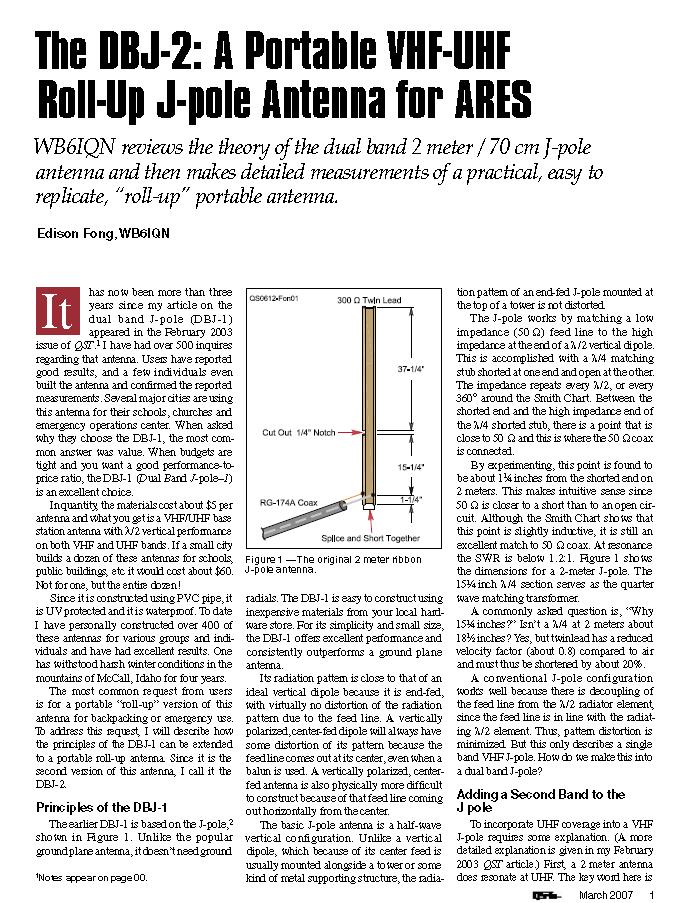
10 300 ohm twinlead 37 1/4 Cut out a 1/4 notch 15 1/4 1 1/4 RG174a coax Splice and short together Figure 1 The original 2 meter ribbon J-Pole. 10 of 30
11 Figure 2 Horizontal pattern of fundamental and 3 rd harmonic. At the third harmonic most of the energy is launched at 45 o. 11 of 30


12 Copper J limited to VHF due to minimum spacing of the parallel pipes. Does not work well for 70cm. 12 of 30
13 Arrow VHF/UHF J-pole does not have decoupling at UHF. 13 of 30

14 According to Dr. Larry Cebik and myself, there is NO validlity to the Slim Jim. Every simulation we have done and physical models both Dr. Cebik and myself have built give the same results as a J-pole. 14 of 30
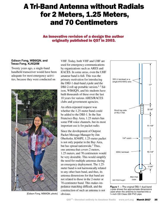
15 300 ohm twinlead 17 Short topside of RG174a 4 1/4 RG174a 11 1/4 Cut out a 1/4 notch 15 1/4 1 1/4 RG174a coax Splice and short together Figure 3 The 2 meter J-pole modified for both VHF and UHF operation. 15 of 30
16 4 Nylon tie for hanging 18 Short topside of RG174a Cut out four 1/4 notches 4 1/4 RG174a 11 1/2 Cover these sections with heat shrinkable tubing Cut out a 1/4 notch 16 1/4 5 ft. of RG174a coax 1 1/4 Splice and short together BNC Connector Figure 4 The dual band J-pole modified for portable operation. Note that dimensions are slightly longer due to the velocity factor of air. 16 of 30
17 Notice that the dimensions on the DBJ-2 (roll up) are longer than the DBJ-1 (base station). This is because we have compensated for the velocity factor of the pvc pipe. The pvc pipe used is very important. We found that Lowe s item #23990 was the best performance for RF. 17 of 30
18 Figure 5a 2 meter J-pole at UHF. Figure 5b DBJ-1 at at UHF. 18 of 30
19 VHF ¼ wave mobile VHF rubber duck Standard VHF J-Pole Dual Band J-Pole -24.7db db db db Table I Measured relative performance of the dual band antenna at 146MHz. UHF ¼ wave mobile UHF rubber duck Standard VHF J-Pole Dual Band J-Pole db db -45 db db 19 of 30

20 Here I am in my lab using the HP8753D 6 GHz network analyzer. 20 of 30
21 445MHz Stub shows a clear resonant at 445MHz. 21 of 30
22 445 MHz marker Hands touching at shorted end. Graphs changes, but not 445MHz resonant point. This says I can place anything at shorted end without affecting the 445MHz resonant high impedance. 22 of 30
23 146 MHz marker 146 MHz marker of the UHF shorted stub. 23 of 30
24 146MHz marker 445 MHz marker of open wire. 24 of 30

25 DBJ-1 mounted on the side of the roof. 25 of 30


26 DBJ-2 kit roll up dual band with BNC, SMA, and reverse SMA. Also 6ft extension cable. 26 of 30
27 1/2 l Approx. 50 ohm points ¼ l RG174A cables ¼ l ½ l Cut out a 1/4 notch 50 W feedpoint 1/4 l voltage and phase distribution Splice and short together RG174a coax to connector The two element UHF phase conlinear with the voltage and phase given on the right. Dimensions are given for insertion into ¾ inch 200 PSI pvc pipe. US patent 8,947, of 30
28 49 12 inches of coiled wired TBJ-1 2mt / 220 MHz/ 70 cm - Tri band antenna with helical loop which allows for insertion into a ¾ inch pvc pipe. Total length is 5 ½ feet which is a practical length for ¾ inch 200 psi pvc pipe. March 2017 QST US Patent 9,608, inches of coiled wired RG174a coaxial cable 28 of 30


29 TBJ-1 is perfect companion to the new Triband radios which run under $ of 30

30 CountyComm GP5/SSB $60 Stereo earphones, external AM ferrite antenna, external shortwave antenna, soft carrying pouch, and user manual The latest and best portable hand held HF SSB receiver in the world. Fully software defined using the SiLabs 4734 DSP chip. Has software defined product detector and DSP SSB filters for true LSB and USB. 450 memories Frequency Coverage MW/ AM: khz (10K tuning step ) SW: MHz AM/SSB/CW (with DSP SSB filters) LW frequency: khz AM/SSB/CW FM: MHz stereo Displays ambient temperature in Fahrenheit or Celsius Operating time: 225 hrs at 40% Volume LCD Backlight 30 of 30
31 DBJ-1 dual band base antenna - available in HAM ( MHz and MHz) or Commercial ( MHz and MHz) $30 DBJ-2 dual band roll up antenna - available in HAM ( MHz and MHz) or Commercial ( MHz and MHz) includes 6ft extension, BNC, SMA and SMA female adapter $28 TBJ-1 triband base antenna 2mt/220 MHz/70 cm - $60 - includes shipping with 6ft of pvc pipe. 50 ft RG8x coax cable with molded PL259 connectors $25 6ft extensions cables (BNC male to BNC female $5 BNC female to PL259 (adapter for roll up DBJ-2 to mobile or base) $2 GP5-SSB Software define radio $60 31 of 30
A Tri Band Antenna for 2 meters, 220 MHz, and 70cm Antenna Without Radials. By: Edison Fong (WB6IQN)
") A Tri Band Antenna for 2 meters, 220 MHz, and 70cm Antenna Without Radials By: Edison Fong (WB6IQN) Twenty years ago a single band handie talkie would have been adequate for emergency use since almost
A Tri Band Antenna for 2 meters, 220 MHz, and 70cm Antenna Without Radials By: Edison Fong (WB6IQN) Twenty years ago a single band handie talkie would have been adequate for emergency use since almost
The DBJ-1: A VHF-UHF Dual-Band J-Pole
 By Edison Fong, WB6IQN The DBJ-1: A VHF-UHF Dual-Band J-Pole Searching for an inexpensive, high-performance dual-band base antenna for VHF and UHF? Build a simple antenna that uses a single feed line for
The DBJ-2: A Portable VHF-UHF Roll-Up J-pole Antenna for Public Service
 The DBJ-2: A Portable VHF-UHF Roll-Up J-pole Antenna for Public Service WB6IQN reviews the theory of the dual band 2 meter / 70 cm J-pole antenna and then makes detailed measurements of a practical, easy
Technician Licensing Class T9
 Technician Licensing Class T9 Amateur Radio Course Monroe EMS Building Monroe, Utah January 11/18, 2014 January 22, 2014 Testing Session Valid dates: July 1, 2010 June 30, 2014 Amateur Radio Technician
Technician License. Course
 Technician License Course Technician License Course Chapter 4 Lesson Plan Module - 10 Practical Antennas The Dipole Most basic antenna The Dipole Most basic antenna The Dipole Total length is ½ wavelength
The quality you expect at the price you want to pay. Available at: 1 (888) (866)
 (866)") The quality you expect at the price you want to pay Available at: www.wirelessource.ca 1 (888) 430-0660 1 (866) 244-4844 October 2014 VHF Mobile Antennas... P1-5 UHF Mobile Antennas... P6-9 CB Mobile Antennas...
The quality you expect at the price you want to pay Available at: www.wirelessource.ca 1 (888) 430-0660 1 (866) 244-4844 October 2014 VHF Mobile Antennas... P1-5 UHF Mobile Antennas... P6-9 CB Mobile Antennas...
Antenna Design for FM-02
 Antenna Design for FM-02 I recently received my FM-02 FM transmitter which I purchased from WLC. I researched the forum on what antennas where being used by the DIY community and found a nice write-up
4/25/2012. Supplement T9. 2 Exam Questions, 2 Groups. Amateur Radio Technician Class T9A: T9A: T9A: T9A:
 Amateur Radio Technician Class Element 2 Course Presentation ti ELEMENT 2 SUB-ELEMENTS Technician Licensing Class Supplement T9 Antennas, Feedlines 2 Exam Questions, 2 Groups T1 - FCC Rules, descriptions
Technician License Course Chapter 4. Lesson Plan Module 10 Practical Antennas
 Technician License Course Chapter 4 Lesson Plan Module 10 Practical Antennas The Dipole Most basic antenna Total length is ½ wavelength (½ λ) Usual construction: Two equal halves of wire, rod, or tubing
Amateur Extra Manual Chapter 9.4 Transmission Lines
 9.4 TRANSMISSION LINES (page 9-31) WAVELENGTH IN A FEED LINE (page 9-31) VELOCITY OF PROPAGATION (page 9-32) Speed of Wave in a Transmission Line VF = Velocity Factor = Speed of Light in a Vacuum Question
2m 70cm Dual Band High Performance Gain Base Station Antenna
 2m 70cm Dual Band High Performance Gain Base Station Antenna We have made it easy for you to find a PDF Ebooks without any digging. And by having access to our ebooks online or by storing it on your computer,
Portable or Emergency VHF Antennas Paul R. Jorgenson KE7HR
 For emergency or public service events it is often necessary to have more antenna than the rubber duck on your handheld VHF radio. Nearly ANY external antenna will provide more coverage for your handheld
TWO METER HOMEMADE SLIM JIM ANTENNA
 Gordon Gibby July 15, 2016 TWO METER HOMEMADE SLIM JIM ANTENNA WIRE: Start with a piece of solid #14 AWG household wire approximately 3 yards and 9 inches long (117 ) (It is easier to be a couple inches
The Amazing MFJ 269 Author Jack Tiley AD7FO
 The Amazing MFJ 269 Author Jack Tiley AD7FO ARRL Certified Emcomm and license class Instructor, Volunteer Examiner, EWA Technical Coordinator and President of the Inland Empire VHF Club What Can be Measured?
MFJ-249B HF/VHF SWR ANALYZER
 TABLE OF CONTENTS MFJ-249B... 2 Introduction... 2 Powering The MFJ-249B... 3 Battery Installation... 3 Alkaline Batteries... 3 NiCd Batteries... 4 Power Saving Mode... 4 Operation Of The MFJ-249B...5 SWR
Least understood topics by most HAMs RF Safety Ground Antennas Matching & Feed Lines
 Least understood topics by most HAMs RF Safety Ground Antennas Matching & Feed Lines Remember this question from the General License Exam? G0A03 (D) How can you determine that your station complies with
A short, off-center fed dipole for 40 m and 20 m by Daniel Marks, KW4TI
 A short, off-center fed dipole for 40 m and 20 m by Daniel Marks, KW4TI Version 2017-Nov-7 Abstract: This antenna is a 20 to 25 foot long (6.0 m to 7.6 m) off-center fed dipole antenna for the 20 m and
Technician Licensing Class. Antennas
 Technician Licensing Class Antennas Antennas A simple dipole mounted so the conductor is parallel to the Earth's surface is a horizontally polarized antenna. T9A3 Polarization is referenced to the Earth
4/29/2012. General Class Element 3 Course Presentation. Ant Antennas as. Subelement G9. 4 Exam Questions, 4 Groups
 General Class Element 3 Course Presentation ti ELEMENT 3 SUB ELEMENTS General Licensing Class Subelement G9 Antennas and Feedlines 4 Exam Questions, 4 Groups G1 Commission s Rules G2 Operating Procedures
FCC Technician License Course
 FCC Technician License Course 2014-2018 FCC Element 2 Technician Class Question Pool Presented by: Tamiami Amateur Radio Club (TARC) WELCOME To the third of 4, 3-hour classes presented by TARC to prepare
Chapter 6 Antenna Basics. Dipoles, Ground-planes, and Wires Directional Antennas Feed Lines
 Chapter 6 Antenna Basics Dipoles, Ground-planes, and Wires Directional Antennas Feed Lines Some General Rules Bigger is better. (Most of the time) Higher is better. (Most of the time) Lower SWR is better.
MFJ-219/219N 440 MHz UHF SWR Analyzer TABLE OF CONTENTS
 MFJ-219/219N 440 MHz UHF SWR Analyzer TABLE OF CONTENTS Introduction...2 Powering The MFJ-219/219N...3 Battery Installation...3 Operation Of The MFJ-219/219N...4 SWR and the MFJ-219/219N...4 Measuring
Optimizing Your Stations Performance
 Optimizing Your Stations Performance A few hints / techniques, recommendations for getting the most RF out to the Antenna from your HF, VHF / UHF station. Tonights Presenters: Doug Theriault NO1D John
The Fabulous Dipole. Ham Radio s Most Versatile Antenna
 The Fabulous Dipole Ham Radio s Most Versatile Antenna 1 What is a Dipole? Gets its name from its two halves One leg on each side of center Each leg is the same length It s a balanced antenna The voltages
Ready and willing to sustain our community in times of emergencies.
 Newsletter of the Wanderers Amateur Radio Club Vol. 2 No. 6: Oct 2018 KM6EON-R EchoLink-L #717585 445.060 MHz - PL 186.2 UTC -8 /-7 DST ITU 6 CQ 3 DM04wc http://www.neighborhoodlink.com/geco wanderersarc@gmail.com
VHF/UHF Beyond FM Bob Witte KØNR Page 1
 VHF/UHF Beyond FM Technical Coordinator Colorado Section Page 1 Objective The objective of this presentation is to provide an introduction to operating on VHF/UHF, going beyond the usual FM / Repeater
Constructing VHF/UHF Antennas WB5CXC Larry Brown W5WF Charles Webb
 Constructing VHF/UHF Antennas WB5CXC Larry Brown W5WF Charles Webb We will be discussing construction of VHF/UHF antenna for portable and home use using common available materials. Our favorite supplies
CHAPTER 8 ANTENNAS 1
 CHAPTER 8 ANTENNAS 1 2 Antennas A good antenna works A bad antenna is a waste of time & money Antenna systems can be very inexpensive and simple They can also be very expensive 3 Antenna Considerations
Cray Valley Radio Society. Real Life Wire Antennas
 Cray Valley Radio Society Real Life Wire Antennas 1 The basic dipole The size of an antenna is determined by the wavelength of operation In free space: ~3x10 8 m/s Frequency x Wavelength = Speed of Light,
RigExpert AA-170 Antenna Analyzer (0.1 to 170 MHz) User s manual
 User s manual") RigExpert AA-170 Antenna Analyzer (0.1 to 170 MHz) User s manual Table of contents 1. Description... 3 2. Specifications... 4 3. Precautions... 5 4. Operation... 6 4.1. Preparation for use... 6 4.2. Turning
RigExpert AA-170 Antenna Analyzer (0.1 to 170 MHz) User s manual Table of contents 1. Description... 3 2. Specifications... 4 3. Precautions... 5 4. Operation... 6 4.1. Preparation for use... 6 4.2. Turning
Antennas Demystified Antennas in Emergency Communications. Scott Honaker N7SS
 Antennas Demystified Antennas in Emergency Communications Scott Honaker N7SS Importance of Antennas Antennas are more important than the radio A $5000 TV with rabbit ears will have a lousy picture Antennas
and Related Topics W7KVI, HARC Original: 3/26/16
 Baluns, Ununs, and Related Topics W7KVI, HARC Original: 3/26/16 This Presentation Informal & brisk - 52 slides (too many unless you re an enthusiast!) Discussion encouraged if not extensive, interrupt
July 1995 QST Volume 79, Number 7
 Lab Notes Prepared by the ARRL Laboratory Staff (e-mail: tis@arrl.org) By Mike Tracy, KC1SX Technical Information Service Coordinator Q: I m just getting started on VHF and UHF FM and I want to set up
LT-800 Stationary Transmitter
 LT-800 Stationary Transmitter Configuration Stationary FM Transmitter (72 MHz) Stationary FM Transmitter (216 MHz) Stationary FM Transmitter (863 MHz) Thanks to its outstanding audio quality, the Listen
End Fed Half Wave Antenna Coupler
 End Fed Half Wave Antenna Coupler The finished End Fed Half Wave antenna coupler. Centre fed half wave dipoles make great, simple and effective antennas for the HF bands. Sometimes however, the centre
Hardware Store 40m Magnetic Loop Antenna for Regional and EMCOM Use. Richard Bono NO5V. QST Antenna Design Competition 80 through 10 meter entry
 Hardware Store 40m Magnetic Loop Antenna for Regional and EMCOM Use Richard Bono NO5V QST Antenna Design Competition 80 through 10 meter entry Overview: This describes a field deployable magnetic loop
AA-35 ZOOM. RigExpert. User s manual. Antenna and cable analyzer
 AA-35 ZOOM Antenna and cable analyzer RigExpert User s manual . Table of contents Introduction Operating the AA-35 ZOOM First time use Main menu Multifunctional keys Connecting to your antenna SWR chart
L. B. Cebik, W4RNL. Basic Transmission Line Properties
 L. B. Cebik, W4RNL In the course of developing this collection of notes, I have had occasion to use and to refer to both series and parallel coaxial cable assemblies. Perhaps a few notes specifically devoted
Portable Magnetic Loop Antenna Version Two
 Portable Magnetic Loop Antenna Version Two The entire antenna assembled and hung up. Note the tuning head at the top matching unit at the bottom, with the spreader supported by the old felt tip pen lids
Development of a noval Switched Beam Antenna for Communications
 Master Thesis Presentation Development of a noval Switched Beam Antenna for Communications By Ashraf Abuelhaija Supervised by Prof. Dr.-Ing. Klaus Solbach Institute of Microwave and RF Technology Department
MFJ-949E. tuner antenowy skrzynka antenowa. Instrukcja obsługi. importer:
 Instrukcja obsługi MFJ-949E tuner antenowy skrzynka antenowa importer: PRO-FIT Centrum Radiokomunikacji InRadio ul. Puszkina 80 92-516 Łódź tel: 42 649 28 28 e-mail: biuro@inradio.pl www.inradio.pl MFJ-949E
Port P able ort Magnet Magne ic Loop Ant An e t nna KG5EAO Rick Bono August Augus 11, 2015
 Portable Magnetic Loop Antenna KG5EAO Rick Bono August 11, 2015 Overview Develop a portable magnetic loop antenna for use on HF bands running QRP. Easy to deploy Ideally run on 40m through 10m bands For
WA4DXP. Mobile Antennas. Mounts, Antennas, Tuners (or not) & grounding Presented by M.D. Smith
 & grounding Presented by M.D. Smith") WA4DXP Mobile Antennas Mounts, Antennas, Tuners (or not) & grounding Presented by M.D. Smith Mounts Mobile Antennas WA4DXP Bolt on antenna mount... Same as used on heavy truck mirror mount Sheet metal
WA4DXP Mobile Antennas Mounts, Antennas, Tuners (or not) & grounding Presented by M.D. Smith Mounts Mobile Antennas WA4DXP Bolt on antenna mount... Same as used on heavy truck mirror mount Sheet metal
Portable Antenna Systems
 Portable Antenna Systems Dr. John A. Allocca, WB2LUA www.wb2lua.com 3/6/16 System 1 - HF / VHF / UHF Tripod VHF/UHF Antenna Dipole Mount HF Hamstick Case! 1 of! 5 Introduction This antenna configuration
ANTENNAS. I will mostly be talking about transmission. Keep in mind though, whatever is said about transmission is true of reception.
 Reading 37 Ron Bertrand VK2DQ http://www.radioelectronicschool.com ANTENNAS The purpose of an antenna is to receive and/or transmit electromagnetic radiation. When the antenna is not connected directly
Technician Licensing Class. Lesson 4. presented by the Arlington Radio Public Service Club Arlington County, Virginia
 Technician Licensing Class Lesson 4 presented by the Arlington Radio Public Service Club Arlington County, Virginia 1 Quiz Sub elements T6 & T7 2 Good Engineering Practice Sub element T8 3 A Basic Station
Adjust Antenna Tuners Antenna Measurements Capacitor Measurement Measure Feed Point Impedance Measure Ground Loss Inductor Measurement
 The Micro908 antenna analyzer is an extremely useful instrument to have around the ham shack or homebrewer s workbench. This section describes the basic uses, as well as some advanced techniques for which
Active Antennas 4/28/2017
 1 Active Antenna??? What Why Theory Loops Verticals Dipoles Amplifier Considerations VE7KW experiments 2 What Simply an antenna with an amplifier - Automotive application - My first exposure to active
LT-800 Stationary FM Transmitter
 LT-800 Stationary FM Transmitter Thanks to its outstanding audio quality, the Listen LT-800 Stationary Transmitter can be used in a variety of applications. The LT-800 is connected to your main audio system,
A Transmatch for Balanced or Unbalanced Lines
 A Transmatch for Balanced or Unbalanced Lines Most modern transmitters are designed to operate into loads of approximately 50 Ω. Solid-state transmitters produce progressively lower output power as the
Portable Vertical Antenna for 75m & 40m
 Portable Vertical Antenna for 75m & 40m BOXBORO August 2012 Jacques VE2AZX Web: ve2azx.net 1 Objectives 1- Portable Antenna for 75m et 40m 2- Low radiation angle for DX 3- Efficient 4- Easy to install.
Some hints/tips on how to assemble nice COAX TRAPS!
 Some hints/tips on how to assemble nice COAX TRAPS! Before we start to assemble our traps, here some general info as introduction : Coax traps are cheap, easy to assemble in a reproducible manner, very
Basic Wire Antennas. Part II: Loops and Verticals
 Basic Wire Antennas Part II: Loops and Verticals A loop antenna is composed of a single loop of wire, greater than a half wavelength long. The loop does not have to be any particular shape. RF power can
INSTRUCTION MANUAL V-42R. Dual Band Collinear Gain Vertical for MHz and GENERAL DESCRIPTION
 308 Industrial Park Road, Starkville, MS 39759 USA Ph: (662) 323-9538 FAX: (662) 323-6551 V-42R Dual Band Collinear Gain Vertical for 144-148 MHz and 436-450 INSTRUCTION MANUAL GENERAL DESCRIPTION The
SWR myths and mysteries.
 SWR myths and mysteries. By Andrew Barron ZL3DW September 2012 This article will explain some of the often misunderstood facts about antenna SWR at HF and uncover some popular misconceptions. The questions
TZ-RD-1740 Rotary Dipole Instruction Manual
 TZ-RD-1740 17/40m Rotary Dipole Instruction Manual The TZ-RD-1740 is a loaded dipole antenna for the 40m band and a full size rotary dipole for the 17m band. The antenna uses an aluminium radiating section
Yana Dongles Tom Berger K1TRB (c)2016 v171227
2016 v171227") Yana Dongles Tom Berger K1TRB (c)2016 v171227 These notes elaborate some items described in the Build notes, and add some more dongles enhancing Yana. Every effort has been exerted to save on the cost
Yana Dongles Tom Berger K1TRB (c)2016 v171227 These notes elaborate some items described in the Build notes, and add some more dongles enhancing Yana. Every effort has been exerted to save on the cost
MFJ-969 Versa Tuner II Instruction Manual
 MFJ-969 Versa Tuner II Instruction Manual General Information The MFJ-969 is a 300 watt RF output power antenna tuner that will match any transmitter or transceiver to virtually any antenna. Peak or average
Antennas and Stuff. John Kernkamp WB4YJT
 Antennas and Stuff John Kernkamp WB4YJT John Kraus W8JK June 28, 1910 - July 18, 2004 Invented the helical antenna, the corner reflector, and the W8JK End-Fire array. In 1950 designed and built the Big
Antennas and Propagation Chapters T4, G7, G8 Antenna Fundamentals, More Antenna Types, Feed lines and Measurements, Propagation
 Antennas and Propagation Chapters T4, G7, G8 Antenna Fundamentals, More Antenna Types, Feed lines and Measurements, Propagation =============================================================== Antenna Fundamentals
Table of Contents. MFJ-1778 G5RV Multiband Antenna
 Table of Contents MFJ-1778 G5RV Multiband Antenna Introduction... 1 Theory Of Operation... 1 80 meter band:... 1 40 meter band:... 1 30 meter band:... 2 20 meter band:... 2 17 meter band:... 2 15 meter
Coming next: Wireless antennas for beginners
 Coming next: Wireless antennas for beginners In other rooms: Logbook of the World (Sussex Suite) SO2R contest operation (Stable Suite) Wires for your wireless: Simple wire antennas for beginners dominic
Tuning a 160M full sized vertical with strong AM broadcast RF present on the antenna. Jay Terleski, WX0B
 Tuning a 160M full sized vertical with strong AM broadcast RF present on the antenna. Jay Terleski, WX0B I often get asked about how to match a ¼ WL vertical to a 50 ohm transmission line and what to do
Jacques Audet VE2AZX ve2azx.net
 Jacques Audet VE2AZX ve2azx.net VE2AZX@amsat.org September 2002 rev. May 2013 1 INTRO WHY USE DUPLEXERS? BASIC TYPES OF DUPLEXERS SIMPLE LC MODELS FOR EACH TYPE ADJUSTMENT AND VERIFICATION PUTTING IT ALL
The EMCOMM Easytenna
 The EMCOMM Easytenna This document will detail how to build an easy to install multiband dipole type antenna for emergency communications using the NVIS propagation mode. History The NVIS mode is one in
An Introduction to Radio Frequency Interference
 An Introduction to Radio Frequency Interference Ron Hranac, N0IVN Member, ARRL EMC Committee ARRL Colorado Section Technical Specialist What is RFI? RFI is an abbreviation for radio frequency interference
Antenna. Wave length Km/s
 Antenna 5% Wave length 300 000 Km/s 066 velocity factor RG-58 = C = = F : 120 Impedance 50 50 50 VSWR and Reflected Power SWR VSWR VSWR 2:1 Voltage Standing Wave Ratio VSWR 15:1 15:1 VSWR 100 Watt 1:1
Milton Keynes Amateur Radio Society (MKARS)
") Milton Keynes Amateur Radio Society (MKARS) Intermediate Licence Course Feeders Antennas Matching (Worksheets 31, 32 & 33) MKARS Intermediate Licence Course - Worksheet 31 32 33 Antennas Feeders Matching
Milton Keynes Amateur Radio Society (MKARS) Intermediate Licence Course Feeders Antennas Matching (Worksheets 31, 32 & 33) MKARS Intermediate Licence Course - Worksheet 31 32 33 Antennas Feeders Matching
Antenna? What s That? Chet Thayer WA3I
 Antenna? What s That? Chet Thayer WA3I Space: The Final Frontier Empty Space (-Time) Four dimensional region that holds everything Is Permeable : It requires energy to set up a magnetic field within it.
20m G4BUD Mobile Whip
 This particular antenna was built specifically to take on holiday to Fuerteventura in the Canary Islands, after it was originally tested from an inland site in the UK. Amongst my first contacts using the
RX Directional Antennas. Detuning of TX Antennas.
 1. Models Impact of Resonant TX antennas on the Radiation Pattern of RX Directional Antennas. Detuning of TX Antennas. Chavdar Levkov, lz1aq@abv.bg, www.lz1aq.signacor.com 2-element small loops and 2-element
A Guide to building your own Portable Station Incorporating a ¼ Wave Vertical Antenna and a Ground Tuning Unit or GTU
 A Guide to building your own Portable Station Incorporating a ¼ Wave Vertical Antenna and a Ground Tuning Unit or GTU Date: 06.02.2016 By: Alex Ball VK2HAS Credits: I was introduced to the GTU by Dave
AD5X. Low Cost HF Antennas & Accessories. Phil Salas - AD5X Phil Salas AD5X. Richardson, Texas
 Low Cost HF Antennas & Accessories Phil Salas - AD5X ad5x@arrl.net PVC Tubing PVC pipe: Considers the inside diameter (ID) of the pipe. For PVC pipe (schedule 40): 1/2" PVC pipe has an ID of 0.6" and an
THE W3FF HOMEBREW BUDDIPOLE
 THE W3FF HOMEBREW BUDDIPOLE A PORTABLE ANTENNA DESIGN FOR AMATEUR RADIO History of the Buddipole In January of 2000, I began experimenting with a walking portable ham station. Since then, thousands of
Fundamentals of Antennas. Prof. Ely Levine
 Fundamentals of Antennas Prof. Ely Levine levineel@zahav.net.il 1 Chapter 3 Wire Antennas 2 Types of Antennas 3 Isotropic Antenna Isotropic radiator is the simplest antenna mathematically Radiates all
Rx antennas at IV3PRK: the 4-Square Rx Vertical Array
 Rx antennas at IV3PRK: the 4-Square Rx Vertical Array Part 2: putting all stuff together and construction details Calculating the cable lengths by Pierluigi Luis Mansutti IV3PRK The most difficult choice,
Miniature Magnetic Loops By David Posthuma, WD8PUO
 Miniature Magnetic Loops By David Posthuma, WD8PUO Application Notes and Articles A General Overview After several years of curiosity and several months of research, I recently built two magnetic loops.
The HAM Radio Operator's Antenna HANDBOOK by Buck Rogers ( K4ABT, for over 60 years)
") 1 of 29 8/27/2007 8:20 AM Monday, August 27, 2007 Tell your friends, you found it at: Serving HAM Radio since 1959, On the Web Since 1995 Order Toll Free Monday through Friday, 9 am to 4 pm, 1 800 726
1 of 29 8/27/2007 8:20 AM Monday, August 27, 2007 Tell your friends, you found it at: Serving HAM Radio since 1959, On the Web Since 1995 Order Toll Free Monday through Friday, 9 am to 4 pm, 1 800 726
SWL Receiving Antenna Experiments
 SWL Receiving Antenna Experiments Introduction I have a lot to learn about SWL antennas. What follows are some brief experiments I performed in late October 2005. I have been experimenting with a half
CHAPTER 5 PRINTED FLARED DIPOLE ANTENNA
 CHAPTER 5 PRINTED FLARED DIPOLE ANTENNA 5.1 INTRODUCTION This chapter deals with the design of L-band printed dipole antenna (operating frequency of 1060 MHz). A study is carried out to obtain 40 % impedance
J-Poles. Mythbusting J-Pole Antennas
 Mythbusting J-Pole Antennas For an antenna to work correctly, it must do two things well 1) Accept power from the feed line impedance match, SWR (ideally) 1:1 2) Radiate power in a pattern that is useful
Array Solutions. Model AS-AYL-4 4-way K9AY Loop System
 Array Solutions Model AS-AYL-4 4-way K9AY Loop System This is the popular K9AY Loop receiving antenna, as described in the September 1997 issue of QST, The K9AY Terminated Loop-A Compact, Directional Receiving
Transmission Lines As Impedance Transformers
 Transmission Lines As Impedance Transformers Bill Leonard N0CU 285 TechConnect Radio Club 2017 TechFest Topics Review impedance basics Review Smith chart basics Demonstrate how antenna analyzers display
Users Manual. 200W HF/50MHz Band Auto Antenna Tuner. Model HC-200AT
 Users Manual 200W HF/50MHz Band Auto Antenna Tuner Model HC-200AT Caution 1. Never remove or open the tuner cover while transmitting. When there is RF in the circuits of the tuner, there will be high voltage
Beams and Directional Antennas
 Beams and Directional Antennas The Horizontal Dipole Our discussion in this chapter is about the more conventional horizontal dipole and the simplified theory behind dipole based designs. For clarity,
Array Solutions 350 Gloria Rd Sunnyvale, TX USA PHN FAX
 Array Solutions 350 Gloria Rd Sunnyvale, TX 75182 USA PHN 972 203 2008 FAX 972 203 8811 E-MAIL sales@arraysolutions.com Model AS-AYL-4 4-way K9AY Loop System This is the popular K9AY Loop receiving antenna,
MFJ Balanced Line Tuner
 MFJ Balanced Line Tuner Introduction The MFJ-974H balanced line antenna tuner is a fully balanced true balanced line antenna tuner, providing superb current balance throughout a very wide matching range
MFJ-2389 Compact 8 Band Vertical
 MFJ-2389 Compact 8 Band Vertical The MFJ-2389 is an 8 band compact vertical that is designed to operate on 80, 40, 20, 15, 10, 6, 2M, and 70CM bands. The antenna will handle 200W PEP or 50W CW HF or 150W
Lesson 11: Antennas. Copyright Winters Version 1.0. Preparation for Amateur Radio Technician Class Exam
 Lesson 11: Antennas Preparation for Amateur Radio Technician Class Exam Topics Antenna ½ wave Dipole antenna ¼ wave Vertical antenna Antenna polarization Antenna location Beam antennas Test Equipment Exam
ATUs - ANTENNA TUNING UNITS THE ATU. An Antenna Tuning Unit MAKE YOUR OWN ATU
 ATUs - ANTENNA TUNING UNITS THE ATU An Antenna Tuning Unit MAKE YOUR OWN ATU The circuit diagram below shows the circuit for a typical Pi type ATU which seems to be a popular arrange ment for many ATUs.
CP6A. 6 Band Trap Vertical 75-6m
 CP6A 6 Band Trap Vertical 75-6m Instruction Sheet The CP6A is a multi-band trap-vertical antenna for HF bands, covering the 75*, 40, 20, 15, 10m & 6m amateur bands. Made from heavy duty aluminum, the CP6A
Compact Multi-Band Rotatable Dipole Antenna Array
 Compact Multi-Band Rotatable Dipole Antenna Array Dr. John A. Allocca, WB2LUA, www.wb2lua.com, 4/9/12 Introduction Having limited space led to the design of this multi-band antenna array, which has a foot
ANTENNAS Wires, Verticals and Arrays
 ANTENNAS Wires, Verticals and Arrays Presented by Pete Rimmel N8PR 2 1 Tonight we are going to talk about antennas. Anything that will conduct electricity can be made to radiate RF can be called an antenna.
Antenna Matching Within an Enclosure Part II: Practical Techniques and Guidelines
 Antenna Matching Within an Enclosure Part II: Practical Techniques and Guidelines By Johnny Lienau, RF Engineer June 2012 Antenna selection and placement can be a difficult task, and the challenges of
Jacques Audet VE2AZX. Nov VE2AZX 1
 Jacques Audet VE2AZX VE2AZX@amsat.org Nov. 2006 VE2AZX 1 - REASONS FOR USING A BALUN - TYPES OF BALUNS - CHECK YOUR BALUN WITH AN SWR ANALYZER - MEASURING THE IMPEDANCE OF A NUMBER OF FERRITES - IMPEDANCE
Welcome to Ham Radio 201 New General / Extra Session
 Welcome to Ham Radio 201 New General / Extra Session Sponsored by Agenda New Technician / New Licensee 8:00 Kickoff 8:15 VHF/UHF Gear - George 9:00 VHF/UHF Operating - Beric 9:45 VHF Digital Voice George
Installed Radio Testing with the 3500
 Application Note Installed Radio Testing with the 3500 Aeroflex has uniquely designed the Aeroflex 3500 portable radio test set for complete testing of installed radio communication systems. The 3500 is
MFJ-208 VHF SWR Analyzer
 MFJ-208 VHF SWR Analyzer Thank you for purchasing the MFJ-208 VHF SWR Analyzer. The MFJ-208 gives you a direct readout of your antenna's SWR without the need for formulas or indirect readings. The MFJ-
Handheld 3.3GHz Spectrum Analyzer
 Handheld 3.3GHz Spectrum Analyzer Optimum for evaluation of W-CDMA CDMA GSM PDC PHS Wireless LAN Bluetooth 2650 1 FEATURES 2650 1 Compact and lightweight 3.75 lb (1.7 kg) The dimensions are as small as
ALWAYS ATTACH THE SAFETY ROPE TO A STABLE SUPPORT BEFORE ATTEMPTING TO ATTACH THE UNIVERSAL MOUNT TO A WINDOW FRAME OR RAIL.
 MFJ-1623 Introduction The MFJ-1623 was designed to provide portable or permanent HF communications on 30 through 10 meters and VHF on 6 meters. The universal mount design allows the user to install the