A Folding 11-Element Yagi for 432 MHz
|
|
|
- Jared Watson
- 5 years ago
- Views:
Transcription
1 A Folding 11-Element Yagi for 432 MHz Steve Kavanagh, VE3SMA, October Introduction For portable VHF/UHF operation I have found it convenient at times to have some antennas which fold up quickly to take less space in the car. This antenna was designed and built in something of a hurry when VE3RZ and I decided to operate together in the Limited Rover class of the 2015 ARRL September VHF Contest and the space I had formerly used to store my 432 MHz Yagi was now to be occupied by Tony! It seemed to behave as expected during the contest, but has not been subjected to any gain measurements. 2. Dimensions Element diameter: 1/8 inch (solid aluminum parasitic elements, brass tubing for driven element) Boom: ¾ thick pine (made from 1X2), total length 81.5 inches, folds to 41.5 inches Boom depth (top-to-bottom): Mostly about 0.8 inch, tapering up to 1.5 inch at mounting clamp and hinge Tolerances: I tried to stay within +/-1 mm on element positions, perhaps +/-0.5 mm for element lengths Length Corrections: No boom correction factor is applied to the element lengths and it should not be necessary with a wood boom of this thickness. The parasitic element lengths were adjusted according to a simple formula [1] for solid elements, while the tubular driven element was not corrected. Element Distance from rear end of boom (mm) Distance from forward end of boom (mm) Element length in NEC model (mm) End correction (mm) [1] Actual element length (mm) Reflector Driven Element (at (see details below) (none) (see details below) centre) Director Director Director Director Director Director Director Director Director
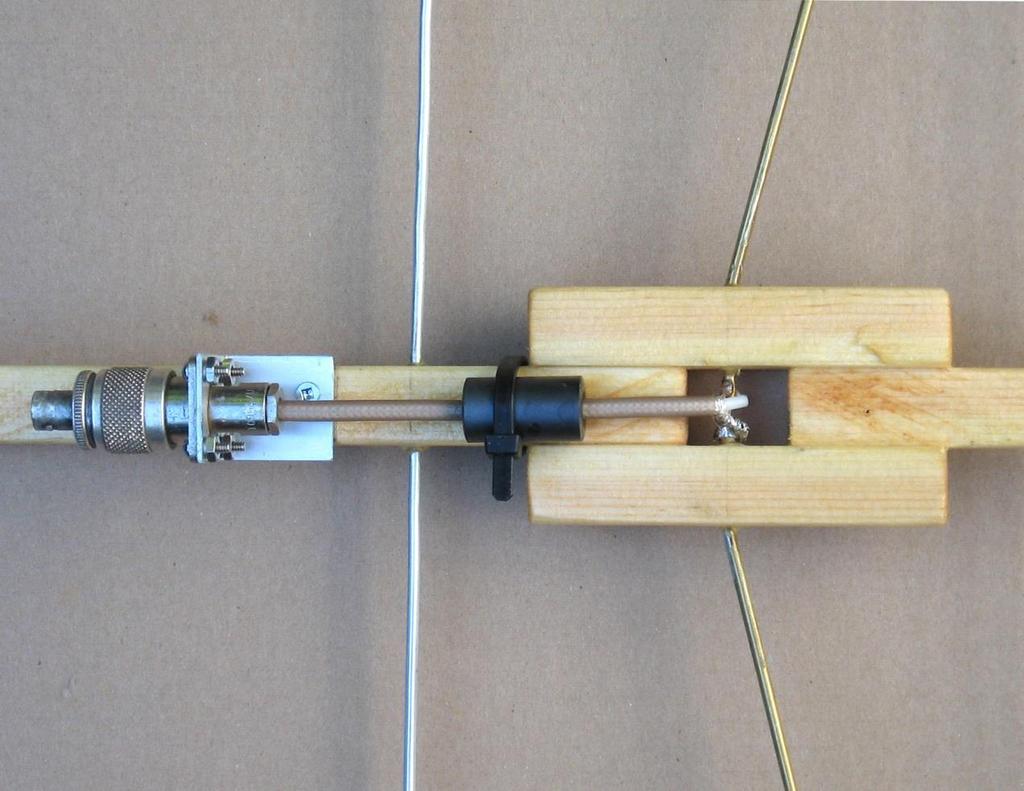
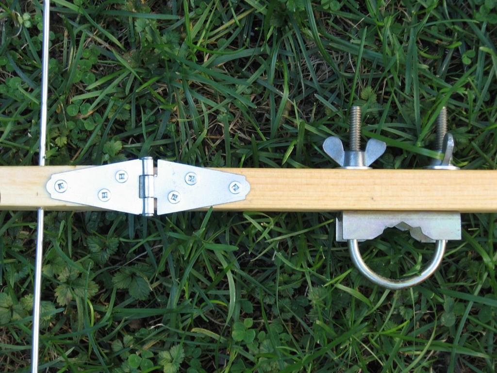
2 3. Boom Details Refer to the sketch below. The boom is made from 1x2 pine (actually ¾ x 1-1/2 ). The front part is 1050 mm long (from the hinge point to the tip). The rear part is made up from 4 pieces. The main part is 894 mm long, from the hinge point to the gap for the driven element. There are two driven element mounting blocks and a reflector support piece (101 mm long) also made from ¾ thick pine, arranged to provide a 25 mm gap around the driven element and a total rear part length of 1020 mm (from the hinge point to the rear end of the boom). The lengths of the driven element mounting blocks is not critical, but they need to be long enough that their joints with the main and reflector mounting parts of the boom are strong enough, but short enough to keep clear of the reflector and first director. In general the boom cross-section is 0.75 x 0.80 inch, but near the hinge point the depth of each part is tapered from 0.8 inch up to the full 1.5 inch dimension of the 1X2 in order to provide a place to attach a mounting clamp and to ensure that the boom is straight when opened out. The rear part pieces are joined together with wood glue and dowels to avoid bringing any additional horizontally polarized metal close to the driven element. I used ¼ inch diameter dowels through all three pieces, with two dowels on each side of the driven element. The hinge is a 2 inch strap hinge fastened to the tops of the boom sections with wood screws (drill pilot holes first to avoid splitting the wood). I found it necessary to tighten the hinge before mounting it to the boom (by squeezing it carefully with vice-grips) to avoid too much wobble. The boom is drilled (1/8 diameter bit) for each of the elements at the positions given in the table). The elements are epoxied into place with a small fillet of epoxy where they exit the wood. The boom is then painted or varnished. Don t paint the elements unless you know very well the RF properties of the paint! 4. Driven Element Details See the following figure. A bent dipole driven element is used for matching and control of coupling to the nearby elements, as introduced by K6STI and developed and described in more detail by DG7YBN [2]. The element halves are inserted in 1/8 holes in the mounting blocks such that there is a 4mm gap between their inner ends, then bent to the right shape. Dimensions of the bent part are to the centre line of the tubing. The driven element should be soldered to the
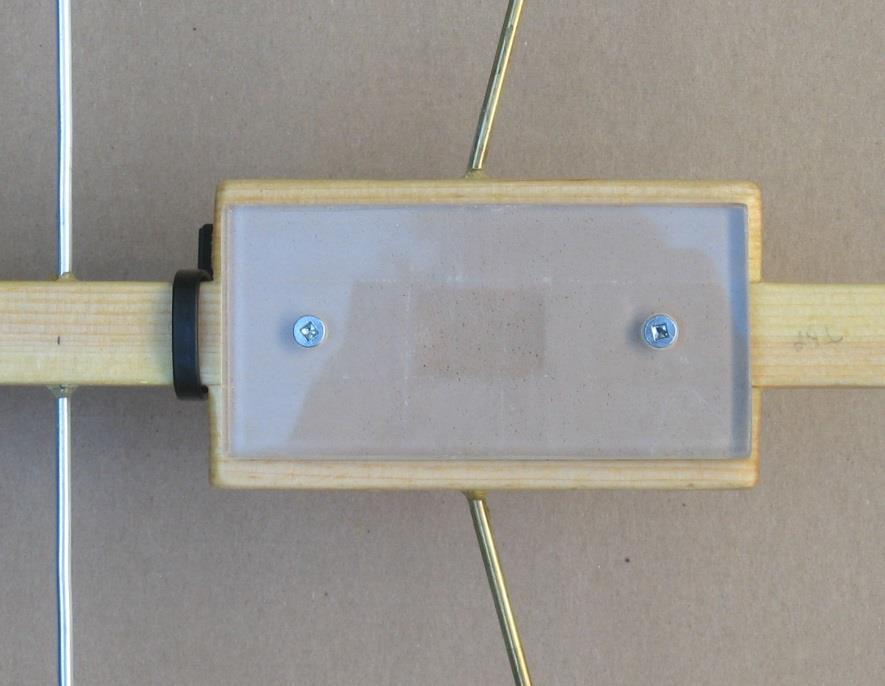
3 coaxial cable, and then epoxied in place, after bending. I found it useful to make a paper template and place it under the antenna when bending the driven element. 5. Balun I put a single inch long by O.D. by I.D. Type 43 ferrite bead on the coax near the driven element to reduce current flowing on the outside of the coaxial cable. The impedance of this as a choke may be a bit marginal and possibly two beads would be better (and could certainly handle more transmitter power). I have used this antenna only at about 10 watts. You can just see the ferrite in the second photo, under the boom between the connector and the driven element. That photo was taken before varnishing the boom. After the varnish was dry I fastened the ferrite bead to the boom with a cable tie, as seen in the third photo. 6. Feed Cover The boom gap at the feed point is protected from rain by a small piece of Plexiglas (any rigid plastic or thin wood would probably do) which is held in place with two screws into the boom. I put a thin piece of foam (from Michael s) between the cover and the wood as a gasket. Alternatively it could be sealed with silicone sealant.
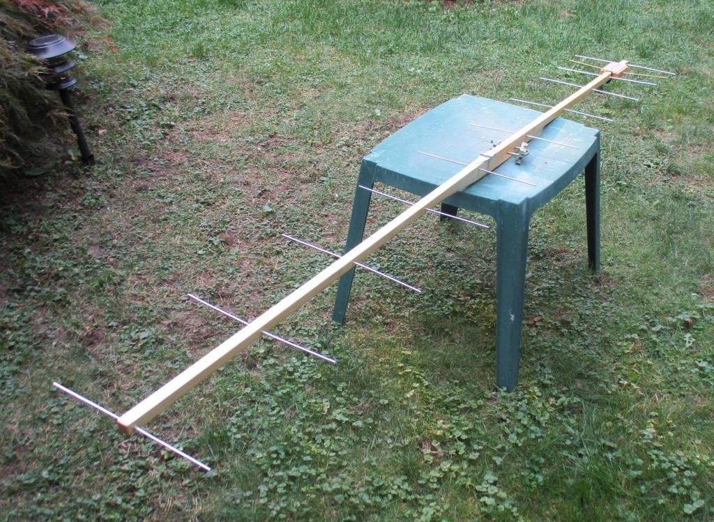
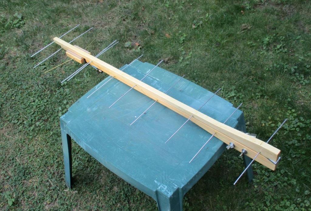
4 7. Photographs
5
6
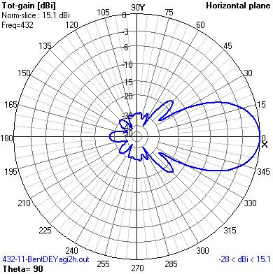
7 8. Predicted Performance Software: 4NEC2 Assumptions: No conductor loss, no balun loss.
![9. References [1] http://www.qsl.](/docs-images/81/84236672/images/8-0.jpg)
8 9. References [1] [2]
A Folding 5-Element Yagi for 144 MHz
 A Folding 5-Element Yagi for 144 MHz Steve Kavanagh, VE3SMA, April 2017 1. Introduction I have found antennas which fold up quickly to take less space in the car to be useful in VHF/UHF portable operating.
9 Element Yagi for 2304 MHz
 9 Element Yagi for 2304 MHz Steve Kavanagh, VE3SMA Design Dipole-based Yagi designs for 2304 MHz are rare, partly because they are a bit tricky to build and partly because the loop yagi has completely
Construction manual for 50 MHz XL design yagi-kits
 Construction manual for 50 MHz XL design yagi-kits Source: http://www.nuxcom.de/pdf/nuxcom_construction-manual_6m-xl.pdf Please check if all parts listed in the invoice are delivered with the kit. In the
Constructing VHF/UHF Antennas WB5CXC Larry Brown W5WF Charles Webb
 Constructing VHF/UHF Antennas WB5CXC Larry Brown W5WF Charles Webb We will be discussing construction of VHF/UHF antenna for portable and home use using common available materials. Our favorite supplies
4 Antennas as an essential part of any radio station
 4 Antennas as an essential part of any radio station 4.1 Choosing an antenna Communicators quickly learn two antenna truths: Any antenna is better than no antenna. Time, effort and money invested in the
Technician License. Course
 Technician License Course Technician License Course Chapter 4 Lesson Plan Module - 10 Practical Antennas The Dipole Most basic antenna The Dipole Most basic antenna The Dipole Total length is ½ wavelength
INSTRUCTION MANUAL. Specifications Electrical. Front-To-Back Ratio VSWR at Resonance Less than 1.5:1 Nominal Impedance. Mechanical
 300 Industrial Park Road, Starkville, MS 39759 Ph: (662) 323-8538 FAX: (662) 323-6551 TH-3JRS Tri-band HF 3 Elements Beam Covers 10, 15 and 20 Meters INSTRUCTION MANUAL WARNING Installation of this product
6M HALO VERSON II + OPTIONAL 2M GROUND PLANE
 The halo is an omnidirectional, horizontally polarized antenna with about the same gain as a dipole but without the low elevation nulls off the ends (+5.5 to +3.5dBi variation for the Halo vs. +7.9 to
Cushcraft. Amateur Radio Antennas LFA-6M5EL. 6 Meter 5 Element Loop Feed Antenna INSTRUCTION MANUAL
 Cushcraft Amateur Radio Antennas LFA-6M5EL 6 Meter 5 Element Loop Feed Antenna INSTRUCTION MANUAL CAUTION: Read All Instructions Before Operating Equipment VERSION 1A Cushcraft Amateur Radio Antennas 308
High Performance 40 Meters Vertical Without Radials
 High Performance 40 Meters Vertical Without Radials This shortened easy-to-build vertical, with no-radials, is made from surplus military camouflage poles. It has gain and wave angle comparable to a full-sized
9el 144MHZ LFA YAGI ASSEMBLY & INSTALLATION MANUAL
 1 9el 144MHZ LFA YAGI ASSEMBLY & INSTALLATION MANUAL 2 WARNING EXTREME CAUTION SHOULD BE TAKEN WHEN CONSTRUCTING AND ERECTING ANTENNA SYSTEMS NEAR POWER AND TELEPHONE LINES. SERIOUS INJURY OR DEATH CAN
MFJ-1762 Instruction Manual
 MFJ-1762 Instruction Manual INTRODUCTION Thank you for purchasing the MFJ-1762 three-element six-meter Yagi. The MFJ-1762 is a light-weight directional antenna especially designed for installation with
MI: (Secure this number someplace, for possible future need) SPECIFICATIONS:
 SPECIFICATIONS:") 6C ASSEMBLY INSTRUCTIONS ANTENNA MODEL T6 MI: 030927 (Secure this number someplace, for possible future need) SPECIFICATIONS: FORWARD GAIN 5.1 dbd F:B RATIO 15-25 db (Rises with frequency) FREQUENCY COVERAGE
6C ASSEMBLY INSTRUCTIONS ANTENNA MODEL T6 MI: 030927 (Secure this number someplace, for possible future need) SPECIFICATIONS: FORWARD GAIN 5.1 dbd F:B RATIO 15-25 db (Rises with frequency) FREQUENCY COVERAGE
Microair Avionics Pty Ltd ABN VHF Aerial Installation FAQ
 Pty Ltd ABN 92 091 040 032 P O Box 5532 Airport Drive Bundaberg West Queensland 4670 Australia Phone: Fax: Email: Web: 07 4155 3048 +61 7 4155 3048 07 4155 3049 +61 7 4155 3049 support@microair.com.au
Clip-on RF Current Meter
 1. Introduction 3. Clip-on RF Current Meter The most useful tool for RF interference troubleshooting! Also in Japanese G0SNO's original article was in RadCom (RSGB) April 1993, page 74. The original Maplin
Improved Ionospheric Propagation With Polarization Diversity, Using A Dual Feedpoint Cubical Quad Loop
 Improved Ionospheric Propagation With Polarization Diversity, Using A Dual Feedpoint Cubical Quad Loop by George Pritchard - AB2KC ab2kc@optonline.net Introduction This Quad antenna project covers a practical
Assembly Instructions: Bencher Skylark
 Assembly Instructions: Bencher Skylark Tools Required: Pop Rivet Tool Tape Measure Hex Wrenches Screwdriver Several Disposable Rags Two Saw Horses Several boxes or bowls to hold fasteners and small parts
M2 Antenna Systems, Inc. Model No: 20M6-125
 M2 Antenna Systems, Inc. Model No: 20M6-125 SPECIFICATIONS: Model... 20M6-125 Frequency Range... 14.0 14.350 MHz *Gain, (FS) / Over gnd... 11.19dBi / 16.6dBi @70 Front to back... 25 db Typical Beamwidth...
M2 Antenna Systems, Inc. Model No: 2M7
 M2 Antenna Systems, Inc. Model No: 2M7 SPECIFICATIONS: Model... 2M7 Frequency Range... 144 To 148 MHz *Gain... 12.3 dbi Front to back... 20 db Typical Beamwidth... E=43 H=50 Feed type... T Match Feed Impedance....
MOUNTING INSTRUCTIONS
 Standard Mounting Bracket Tilting Bracket* Mounting example Right side for upper tilt from 0 to 20 20 Spare parts: p/n SA197 Materials: extruded aluminum Hardware: stainless & zinc plated steel Dimensions
M2 Antenna Systems, Inc. Model No: YAGI ANTENNA
 M Antenna Systems, Inc. Model No: 4.5-7 YAGI ANTENNA SPECIFICATIONS: Model... 4.5-7 Frequency Range... 4.0 To 4.5 MHz *Gain... 0 To 7 dbi Front to back... 0 db over the rear 80 Beamwidth... E=44 H=50 typical
M2 Antenna Systems, Inc. Model No: 20M5LD
 M2 Antenna Systems, Inc. Model No: 20M5LD SPECIFICATIONS: Model... 20M5LD Frequency Range... 14.0 14.350 MHz *Gain (Full Band)... 10.2 dbi Typical Front to back... 23 db Typical Beamwidth... E=50 / H=66
L. B. Cebik, W4RNL. Basic Transmission Line Properties
 L. B. Cebik, W4RNL In the course of developing this collection of notes, I have had occasion to use and to refer to both series and parallel coaxial cable assemblies. Perhaps a few notes specifically devoted
MODEL DB-1015A 10- and 15-Meter Duo-Band Antenna Order No. 330
 MODEL DB-1015A 10- and 15-Meter Duo-Band Antenna Order No. 330 HY-GAIN ELECTRONICS CORPORATION 8601 Northeast Highway 6 Lincoln, Nebraska 68505 Telephone 464-9151 Area Code 402 TABLE OF CONTENTS page SECTION
Directive Systems & Engineering 2702 Rodgers Terrace Haymarket, VA
 Directive Systems & Engineering 2702 Rodgers Terrace Haymarket, VA 20169-1628 www.directivesystems.com 703-754-3876 25 Element 7.4 wl. K1FO Designed Yagi, Model DSEFO432-25 ELECTRICAL SPECIFICATIONS Frequency
A HIGH PERFORMANCE AIRBAND ANTENNA FOR YOUR ULTRALIGHT / LIGHTSPORT AIRCRAFT by Dean A. Scott (revised March, 2018)
") A HIGH PERFORMANCE AIRBAND ANTENNA FOR YOUR ULTRALIGHT / LIGHTSPORT AIRCRAFT by Dean A. Scott (revised March, 2018) In this article I present a simple, easy to construct, and easy to mount Inverted V halfwave
A HIGH PERFORMANCE AIRBAND ANTENNA FOR YOUR ULTRALIGHT / LIGHTSPORT AIRCRAFT by Dean A. Scott (revised March, 2018) In this article I present a simple, easy to construct, and easy to mount Inverted V halfwave
A IVE-BAND, TWO-ELEMENT H QUAD
 A IVE-BAND, TWO-ELEMENT H QUAD Two quad designs are described in this article, both nearly identical. One was constructed by KC6T from scratch, and the other was built by Al Doig, W6NBH, using modified
Inexpensive Lightweight High-Performance Small Yagi Antennas for VHF-UHF Portable Operation
 Inexpensive Lightweight High-Performance Small Yagi Antennas for VHF-UHF Portable Operation Rick Campbell KK7B Pacific Northwest VHF Conference Bend, Oregon October 8 2016 But why? We already have: Inexpensive
Model VB-23FM 2-Meter 3-Element Beam
 308 Industrial Park Road Starkville, MS 39759 USA Ph: (662) 323-9538 FAX: (662) Model VB-23FM 2-Meter 3-Element Beam [ INSTRUCTION MANUAL Figure 1 Overall View and Boom Detail GENERAL DESCRIPTION This
BUILD A HIGH PERFORMANCE TWO ELEMENT TRI-BAND CUBICAL QUAD. By Bob Rosier K4OCE INTRODUCTION THEORY AND GENERAL INFORMATION
 BUILD A HIGH PERFORMANCE TWO ELEMENT TRI-BAND CUBICAL QUAD INTRODUCTION By Bob Rosier K4OCE Lots of DX can be worked with a dipole at the QRP level, however, a beam will obviously give you additional gain
Portable or Emergency VHF Antennas Paul R. Jorgenson KE7HR
 For emergency or public service events it is often necessary to have more antenna than the rubber duck on your handheld VHF radio. Nearly ANY external antenna will provide more coverage for your handheld
Directive Systems & Engineering 2702 Rodgers Terrace Haymarket, VA
 Directive Systems & Engineering 2702 Rodgers Terrace Haymarket, VA 20169 1628 www.directivesystems.com 703 754 3876 K1JX DESIGNED 6 ELEMENT 50 MHZ YAGI, DSEJX6 50 INTRODUCTION The Directive Systems DSEJX6-50
K1FO 12 ELEMENT 144/147 MHz YAGI
 K1FO 12 ELEMENT 144/147 MHz YAGI WARNING: INSTALLATION OF THIS PRODUCT NEAR POWER LINES IS DANGEROUS. FOR YOUR SAFETY FOLLOW THE INSTALLATION DIRECTIONS. Ariane Arrays, Inc. Copyright 2006 201 Hopedale
Kentucky 4H Wood Science Plans Notebook. Plans Level 3
 Kentucky 4H Wood Science Plans Notebook Plans Level 3 MATERIALS: 2 pieces wood 3/4 x 10 x 4 1 piece wood 3/4 x 12 x 4 2 pieces wood 3/4 x 3 x 2 5 1/2" 2 pieces wood 3/4 x 3 x 1 8 1 piece wood 2 x 4 x
Intermediate Course (5) Antennas and Feeders
 Antennas and Feeders") Intermediate Course (5) Antennas and Feeders 1 System Transmitter 50 Ohms Output Standing Wave Ratio Meter Antenna Matching Unit Feeder Antenna Receiver 2 Feeders Feeder types: Coaxial, Twin Conductors
Intermediate Course (5) Antennas and Feeders 1 System Transmitter 50 Ohms Output Standing Wave Ratio Meter Antenna Matching Unit Feeder Antenna Receiver 2 Feeders Feeder types: Coaxial, Twin Conductors
A short, off-center fed dipole for 40 m and 20 m by Daniel Marks, KW4TI
 A short, off-center fed dipole for 40 m and 20 m by Daniel Marks, KW4TI Version 2017-Nov-7 Abstract: This antenna is a 20 to 25 foot long (6.0 m to 7.6 m) off-center fed dipole antenna for the 20 m and
Nick Garner N3WG and George Zafiropoulos KJ6VU
 Nick Garner N3WG and George Zafiropoulos KJ6VU Introduction Over the last few years, there has been a significant increase in the number of radio amateurs interested in portable operating. This is due
HexBeam Antenna. Equation 2, for 2.5 < b/w < 4: Zo = * LOG ( * (b/w) Zo = * LOG ( * 2.5) = 49.83Ω
 Zo = * LOG ( * 2.5) = 49.83Ω") HexBeam Antenna T here are numerous articles 1, 2, 3 on the design and construction of this popular 5-band broadband antenna and I decided to build one that utilizes all of the best features. Hub Most
HexBeam Antenna T here are numerous articles 1, 2, 3 on the design and construction of this popular 5-band broadband antenna and I decided to build one that utilizes all of the best features. Hub Most
COAXIAL TRANSMISSION LINE COMMON-MODE CURRENT
 COAXIAL TRANSMISSION LINE COMMON-MODE CURRENT Introduction Coaxial transmission lines are popular for their wide frequency bandwidth and high resistance to electromagnetic interference (EMI). Coax cables
Assembly Instructions for the 1.5 Watt Amplifier Kit
 Assembly Instructions for the 1.5 Watt Amplifier Kit 1.) All of the small parts are attached to a sheet of paper indicating both their value and id. 2.) Leave the parts affixed to the paper until you are
Model 3104C. Biconical Antenna. User Manual
 Model 3104C Biconical Antenna User Manual ETS-Lindgren L.P. reserves the right to make changes to any product described herein in order to improve function, design, or for any other reason. Nothing contained
Coaxial Cable Feeder Influence on Four Stacked Yagi Antennas Array Dragoslav Dobričić, YU1AW
 Coaxial Cable Feeder Influence on Four Stacked Yagi Antennas Array Dragoslav Dobričić, YU1AW dragan@antennex.com Introduction Aprevious article series consisted of two parts [1, 2] showing the results
INSTRUCTION MANUAL. Specifications Mechanical. 1 5/8 to 2 1/16 O.D. (41mm to 52mm)
") 308 Industrial Park Road Starkville, MS 39759 USA Ph: (662) 323-9538 FAX: (662) 323- General Description Model VB-25FM 2-Meter 5 Elements Beam INSTRUCTION MANUAL This antenna is a 5-element, 2-meter beam
308 Industrial Park Road Starkville, MS 39759 USA Ph: (662) 323-9538 FAX: (662) 323- General Description Model VB-25FM 2-Meter 5 Elements Beam INSTRUCTION MANUAL This antenna is a 5-element, 2-meter beam
LJ element beam for 10 or 12 meters INSTRUCTION MANUAL. CAUTION: Read All Instructions Before Operating Equipment
 LJ-113 3 element beam for 10 or 1 meters INSTRUCTION MANUAL CAUTION: Read All Instructions Before Operating Equipment 308 Industrial Park Road Starkville, MS 39759 USA Tel: 66-33-9538 Fax: 66-33-6551 VERSION
A 75-Watt Transmitter for 3 Bands Simplified Shielding and Filtering for TVI BY DONALD H. MIX, W1TS ARRL Handbook 1953 and QST, October 1951
 A 75-Watt Transmitter for 3 Bands Simplified Shielding and Filtering for TVI BY DONALD H. MIX, W1TS ARRL Handbook 1953 and QST, October 1951 The transmitter shown in the photographs is a 3-stage 75-watt
INSTRUCTION MANUAL for MODEL TH6-DX "THUNDERBIRD" (389)
") INSTRUCTION MANUAL for MODEL TH6-DX "THUNDERBIRD" (389) HY-GAIN ELECTRONICS CORPORATION, N. E. Hwy #6 at Stevens Creek, Lincoln, Nebraska 65801 Telephone 434-6331 INTRODUCTION Ely-Gain's new Model TH6-DX
INSTRUCTION MANUAL for MODEL TH6-DX "THUNDERBIRD" (389) HY-GAIN ELECTRONICS CORPORATION, N. E. Hwy #6 at Stevens Creek, Lincoln, Nebraska 65801 Telephone 434-6331 INTRODUCTION Ely-Gain's new Model TH6-DX
A Fox- Hunting DF Twin Tenna
 A Fox- Hunting DF Twin Tenna Interferometers give sharp bearings, but they lack sensitivity for distant work. Yagis are sensitive, but they provide relatively broad bearings. Build an antenna that blends
Hy-gain. Method 1 : Completely assemble the antenna on the ground then hoist it into position using a setup as shown in Figure 1.
 Hy-gain The Hy-Gain TH6-DXX "Super Thunderbird" is a 6-element beam designed to operate on 10, 25 and 20 meters. It has four active elements on 10-meters and three active elements on 15 and 20 meters.
Cushcraft. Amateur Radio Antennas DB-46M8EL. Dual band 6 and 4 Meter, 8 Element Beam Antenna INSTRUCTION MANUAL
 Cushcraft Amateur Radio Antennas DB-46M8EL Dual band 6 and 4 Meter, 8 Element Beam Antenna INSTRUCTION MANUAL CAUTION: Read All Instructions Before Operating Equipment VERSION 1B Cushcraft Amateur Radio
o 7 WA c i e~ma50: Oll"\l m. J VA'! OIP'Q:9b<e~m..~e Il<lUllTZWe~n<eln1DAtriJiterra~~ln1 complrter-desigjned I computer-optimiert
 VA'! OIP'Q:9b
Long ago, I used to build 4m antennas using fishplates to mount ½ diameter elements onto a 1 round boom. The fishplates were sheet aluminium
 Long ago, I used to build 4m antennas using fishplates to mount ½ diameter elements onto a 1 round boom. The fishplates were sheet aluminium pressings made by a local distributor of broadcast radio & TV
M2 Antenna Systems, Inc. Model No: 2M5WL
 M2 Antenna Systems, Inc. Model No: 2M5WL SPECIFICATIONS: Model... 2M5WL Frequency Range... 144 To 148 MHz *Gain... 16.84 dbi Front to back... 22 db Typical Beamwidth... E=26 H=29 Feed type... T Match Feed
WHY YOU NEED A CURRENT BALUN
 HF OPERATORS WHY YOU NEED A CURRENT BALUN by John White VA7JW NSARC HF Operators 1 What is a Balun? A BALUN is a device typically inserted at the feed point of a dipole-like antenna wire dipoles, Yagi
Note - the nose ribs and are thinner than the main ribs. These nose ribs will use a thinner rib cap than the ribs. This is per design.
 Stabilizer rev 1.2 The SE5a stabilizer is the heartbeat of the tail and is recreated like the full scale version. All tail pieces depend on the stabilizer. It uses the steel fittings, pulleys, inspection
TZ-RD-1740 Rotary Dipole Instruction Manual
 TZ-RD-1740 17/40m Rotary Dipole Instruction Manual The TZ-RD-1740 is a loaded dipole antenna for the 40m band and a full size rotary dipole for the 17m band. The antenna uses an aluminium radiating section
INSTRUCTION MANUAL VB-66DX. 6-Meter 6-Element Beam. Preparation For Assembly. General Description
 VB-66DX 308 Industrial Park Road Starkville, MS 39759 USA Ph: (662) 323-9538 FAX: (662) 323-6551 6-Meter 6-Element Beam INSTRUCTION MANUAL General Description The Hy-Gain Model 66DX is a full sized 6-
MODEL RA-7, 2-Element and MODEL RA-17, 3-Element RUGGEDIZED Folding VHF Directional Hand-held Antennas. User s Guide and Specifications
 TELEMETRY-ELECTRONICS CONSULTANTS 932 E. IMPALA AVENUE MESA, ARIZONA 85204-6699 U.S.A. TEL (480) 892-4444 FAX (480) 892-9139 E-MAIL info@telonics.com www.telonics.com MODEL RA-7, 2-Element and MODEL RA-17,
TELEX, liutiiilio"i TELEX COMMUNICATIONS, INC ALDRICH AVE. SO. MINNEAPOLIS. MN USA
 TELEX, liutiiilio"i TELEX COMMUNICATIONS, INC. 9600 ALDRICH AVE. SO. MINNEAPOLIS. MN 55420 USA INSTRUCTION MANUAL ORDER NO. 410 General This antenna is a five-element, Citizens Band beam with a forward
M2 Antenna Systems, Inc. Model No: 2M4
 M2 Antenna Systems, Inc. Model No: 2M4 SPECIFICATIONS: Model... 2M4 Frequency Range... 144 To 148 MHz *Gain... 9.6 dbi Front to back... 20 db Typical Beamwidth... E=54 H=74 Feed type... T Match Feed Impedance....
Using Ferrite Beads Keep RF Out of TV Sets, Telephones, VCR's Burglar Alarms and other Electronic Equipment
 Using Ferrite Beads Keep RF Out of TV Sets, Telephones, VCR's Burglar Alarms and other Electronic Equipment RFI and TVI have been with us for a long time. Now we have microwave ovens, VCR's and many other
The Quagi Antenna Turns 30
 The Quagi Antenna Turns 30 By Wayne Overbeck, N6NB www.n6nb.com It has been 30 years since the VHF-UHF Quagi antenna--a combination of the desirable features of a Yagi and a cubical quad--was developed
Milton Keynes Amateur Radio Society (MKARS)
") Milton Keynes Amateur Radio Society (MKARS) Intermediate Licence Course Feeders Antennas Matching (Worksheets 31, 32 & 33) MKARS Intermediate Licence Course - Worksheet 31 32 33 Antennas Feeders Matching
Milton Keynes Amateur Radio Society (MKARS) Intermediate Licence Course Feeders Antennas Matching (Worksheets 31, 32 & 33) MKARS Intermediate Licence Course - Worksheet 31 32 33 Antennas Feeders Matching
SatNOGS. Helical Antenna v4. Written By: Pierros Papadeas. Make your own SatNOGS v4 Helical UHF Antenna. Helical Antenna v4
 SatNOGS Helical Antenna v4 Make your own SatNOGS v4 Helical UHF Antenna Written By: Pierros Papadeas 2017 satnogs.dozuki.com Page 1 of 13 INTRODUCTION This is a guide to build Helical UHF Antenna v4. The
Preliminary pilot information
 Recommended RC-components: Preliminary pilot information RC-component suggestions for Freestyler 3, V-tail version FLAPS AILERONS V-tail receiver battery low-cost HS85 MG HS85 MG HS81 MG SMC 14 4 x AA
Water Rocket Launcher
 Rocket Activity Water Rocket Launcher Objective Construct a launch platform for launching water rockets. National Science Content Standards Physical Science Position and motion of objects Motions and forces
M2 Antenna Systems, Inc. Model No: 2MCP22
 M2 Antenna Systems, Inc. Model No: 2MCP22 SPECIFICATIONS: Model... 2MCP22 Frequency Range... 144 To 148 MHz *Gain... 14.39 dbic Front to back... 25 db Typical Elipticity... >3db Beamwidth... 38 Feed type...
INSTRUCTION MANUAL. Model VB-215DX MECHANICAL DESIGN GENERAL DESCRIPTION ELECTRICAL DESIGN. 2 Meter 15 Element Yagi for SSB/CW
 Model VB-215DX 2 Meter 15 Element Yagi for SSB/CW INSTRUCTION MANUAL GENERAL DESCRIPTION The Hy-Gain Model 215DX is a high performance yagi antenna for SSB/CW DXing in the Amateur 2 meter band. It features
Homebrew your Omnidirectional INMARSAT-C Antenna
 Homebrew your Omnidirectional INMARSAT-C Antenna In this short article we are going to look into the construction details of an old commercial INMARSAT-C Antenna. The purpose of this document is to serve
SPORTCRAFT ANTENNAS. INSTALLATION INSTRUCTIONS for FLUSH WINGTIP COM ANTENNAS
 01A SPORTCRAFT ANTENNAS INSTALLATION INSTRUCTIONS for FLUSH WINGTIP COM ANTENNAS 1.0 INTRODUCTION. 1.1 GENERAL. These antennas have been designed by Bob Archer of Torrance, California utilizing concepts
C O R P O R A T I O N
 ASSEMBLY AND INSTALLATION INSTRUCTIONS A4S 20 / 5 / 0 MeterBeam C O R P O R A T I O N 95279 (8/98) WARNING THIS ANNNA IS AN ELECTRICAL CONDUCTOR. CONTACT WITH POWER LINES CAN RESULT IN DEATH, OR SERIOUS
M2 Antenna Systems, Inc. Model No: KT34XA TO KT36XA UPGRADE KIT
 M2 Antenna Systems, Inc. Model No: KT34XA TO KT36XA UPGRADE KIT SPECIFICATIONS: SPECIFICATIONS for the KT34-6XA MODEL NUMBER...KT36XA FREQ. RANGE...14.0-14.35 MHz 21.0-21.45 MHz 28.0-29.0 MHz GAIN (Free
Antennas and Stuff. John Kernkamp WB4YJT
 Antennas and Stuff John Kernkamp WB4YJT John Kraus W8JK June 28, 1910 - July 18, 2004 Invented the helical antenna, the corner reflector, and the W8JK End-Fire array. In 1950 designed and built the Big
simple and robust feeding system. No phasing lines or matching devices to worry about. spiderbeam on 10m aluminium push-up pole
 The spiderbeam was developed as a DXpeditioner's dream antenna. It is a full size lightweight tribander yagi made of fiberglass and wire. The whole antenna weight is only kg (lbs), making it ideally suited
M2 Antenna Systems, Inc. Model No: KT31WARC
 M2 Antenna Systems, Inc. Model No: KT31WARC SPECIFICATIONS: Model... KT31WARC Frequency Range... 10.1-10.15 MHz **Selectable Frequency Range... 14.0-14.35 MHz **Selectable... (175 KHz / 2:1 VSWR Nominal)
RESolution V2 Manual
 RESolution V2 Manual Note for the German Manual: Yellow Bottle thick CA Pink Bottle Med CA Blue tube 5 minute Epoxy Green tube 90 Minute Epoxy Construction of the Fuselage Step 1: Cover the plan with a
The J-Pole Antenna. Gary Wescom
 The J-Pole Antenna Gary Wescom - 2018 Much has been written about the J-Pole antenna. A simple Google search will net days worth of reading material on the subject. That would tend to indicate this paper
Grounding and Utility Enclosure
 Grounding and Utility Enclosure DXE-UE-2P DXE-UE-2P-INS Rev 1f DX Engineering 2017 1200 Southeast Ave. - Tallmadge, OH 44278 USA Phone: (800) 777-0703 Tech Support and International: (330) 572-3200 Fax:
Chapter 6 Antenna Basics. Dipoles, Ground-planes, and Wires Directional Antennas Feed Lines
 Chapter 6 Antenna Basics Dipoles, Ground-planes, and Wires Directional Antennas Feed Lines Some General Rules Bigger is better. (Most of the time) Higher is better. (Most of the time) Lower SWR is better.
Antennas Demystified Antennas in Emergency Communications. Scott Honaker N7SS
 Antennas Demystified Antennas in Emergency Communications Scott Honaker N7SS Importance of Antennas Antennas are more important than the radio A $5000 TV with rabbit ears will have a lousy picture Antennas
JK-65 Five Element 6M Yagi
 JK-65 Five Element 6M Yagi PO Box 266, Croton Falls, NY 10519-0266 845.228.8700 (TEL) 845.279.5526 (FAX) info@jkantennas.com Page 1 of 8 JK Antennas Limited Warranty and Liability JK Antennas ( Manufacturer
The W3FF Portable Dipole
 The W3FF Portable Dipole This is the antenna I designed for my 'walking portable' station. It is a dipole constructed out of the plastic plumbing pipe CPVC. There are telescoping whips at the ends of each
47 GHz Waveguide Harmonic Mixer
 47 GHz Waveguide Harmonic Mixer These slides present an evolution of harmonic mixer construction ideas. The first slides depict the first harmonic mixer construction details and the later slides depict
Construction Guide: Spiderbeam 40m Add-On Dipole
 6. Spiderbeam 40m Dipole Required Material for Both Versions: Pos QTY Description 1 1210cm Wireman CQ-532 Copperweld Wire 2 986cm Wireman CQ-534 Copperweld Wire 3 210cm Enamel-Insulated Copper Wire 1.5mm
REP Design LLC. 193 Winding Ridge Rd, Southington, CT INSTALLATION INSTRUCTIONS:
 REP Design LLC 193 Winding Ridge Rd, Southington, CT 06489 1-860.426.1894 n7emw@cox.net www.repdesign.us INSTALLATION INSTRUCTIONS: SHD-SO239 Super Heavy Duty SO-239Antenna Mounting System Thank you for
By Paul Melbourne G8GML and Ian Waters G3KKD.
 23cm Panel Antennas By Paul Melbourne G8GML and Ian Waters G3KKD. This article describes a range of panel antennas developed by G8GML. It is a sequel to an article by John Stockley, G8MMY, published in
Pow-R-Feed Systems Service Manual
 Pow-R-Feed Systems Service Manual Important Safety Instructions Please read this manual carefully and follow its instructions. Improper use or failure to follow these instructions could result in serious
Mast and Antennas for Field Day & Emergencies
 Mast and Antennas for Field Day & Emergencies John A. Allocca, WB2LUA, July 2005 This is a 27 feet 1.5 diameter portable guyed mast with a 28 feet diameter footprint. It breaks down into four 6 feet sections
Citabria Pro. Aerobatic Parkflyer. by Joel Dirnberger
 Citabria Pro Aerobatic Parkflyer by Joel Dirnberger Revision C: December 21, 2004 Citabria Pro Building Instructions Length: Wingspan: Wing Area: Flying Weight: Wing Loading: Functions: Specifications:
A HIGH PERFORMANCE AIRBAND ANTENNA FOR YOUR ULTRALIGHT / LIGHTSPORT AIRCRAFT by Dean A. Scott, mfa (revision 3 September 2017)
") A HIGH PERFORMANCE AIRBAND ANTENNA FOR YOUR ULTRALIGHT / LIGHTSPORT AIRCRAFT by Dean A. Scott, mfa (revision 3 September 2017) In this article I present a simple, easy to construct, and easy to mount Inverted
A HIGH PERFORMANCE AIRBAND ANTENNA FOR YOUR ULTRALIGHT / LIGHTSPORT AIRCRAFT by Dean A. Scott, mfa (revision 3 September 2017) In this article I present a simple, easy to construct, and easy to mount Inverted
Atomic Mercury Frame Kit Assembly Manual
 Atomic Mercury Frame Kit Assembly Manual Thank you for purchasing the Atomic Aviation Mercury RACEframe! Please read through the entire manual first before beginning assembly of your kit. The order of
MA5B 20 / 17 / 15 / 12 / 10 Meter Beam Antenna
 ASSEMBLY AND INSTALLATION INSTRUCTIONS NE 20 / 17 / 15 / 12 / 10 Meter Beam Antenna 951485_GF_AB WARNING THIS ANTENNA IS AN ELECTRICAL CONDUCTOR. CONTACT WITH POWER LINES CAN RESULT IN DEATH, OR SERIOUS
Combat Foamie. An electric powered model made from sheet foam for full contact combat matches. Designed by. Plan by Paul Bradley. Jerry W.
 Combat Foamie An electric powered model made from sheet foam for full contact combat matches Designed by Jerry W. Hagood Plan by Paul Bradley July 2010 Combat Foamie Top View 22.9 CG is 7.3 back from nose
EH-20 20m antenna. By VE3RGW
 EH-20 20m antenna By VE3RGW Equivalent circuit of EH-20 antenna system. Upper cylinder Lower cylinder Phasing coil Common mode radiator Tune coil RF choke or 14MHz trap 50ohm coaxial cable 0-150pF (case
HMS Hairpin Matching Systems
 HMS Hairpin Matching Systems DXE-HMS-1P, DXE-HMS-2P, DXE-HMS-4P DXE-HMS-INS-Rev 1h For Use with 1-1/4 Inch through 3 Inch Booms Shown with optional Boom, Elements and Element Bracket with Gorilla Grip
Lesson 11: Antennas. Copyright Winters Version 1.0. Preparation for Amateur Radio Technician Class Exam
 Lesson 11: Antennas Preparation for Amateur Radio Technician Class Exam Topics Antenna ½ wave Dipole antenna ¼ wave Vertical antenna Antenna polarization Antenna location Beam antennas Test Equipment Exam
M2 Antenna Systems, Inc. Model No: 436CP30
 M2 Antenna Systems, Inc. Model No: 436CP30 SPECIFICATIONS: Model... 436CP30 Frequency Range... 432 To 440 MHz *Gain... 15.50 dbic Front to back... 18 db Typical Elipticity... 1.5 db Typical Beamwidth...
Resonant Antennas: Wires and Patches
 Resonant Antennas: Wires and Patches Dipole Antennas Antenna 48 Current distribution approximation Un-normalized pattern: and Antenna 49 Radiating power: For half-wave dipole and,, or at exact resonance.
DB Duo-Monoband Beam 7 - Element, 12 and 17 Meter INSTRUCTION MANUAL. General Description
 308 Industrial Park Road Starkville, MS 39759 USA Ph: (662) 323-9538 FAX: (662) 323-6551 DB- 1217 Duo-Monoband Beam 7 - Element, 12 and 17 Meter INSTRUCTION MANUAL General Description The Hy-Gain DB-1217
Please read and understand all instructions before building!
 The X-Calibur kit contains all the parts necessary* to build a flying high power rocket: (1) Pre-slotted main airframe (1) Payload airframe (1) Airframe coupler tube (1) Coupler bulkplate (1) Coupler hardware
Yagi beam antennas CHAPTER 10 COMPOSITION OF A BEAM ANTENNA _
 CHAPTER 10 Yagi beam antennas The Yagi beam antenna (more correctly, the Yagi Uda antenna, after both of the designers of Tohoku University in Japan 1926) is unidirectional. It can be vertically polarized