Plotting all this data got old using a chart to look up VSWR each time. Here is a formula I found rooting around the web. Let Excel do the work
|
|
|
- Winifred Wiggins
- 5 years ago
- Views:
Transcription
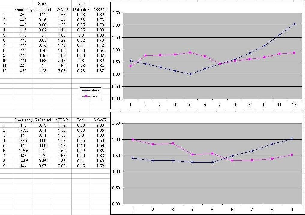
1 My compliments to John, K5GD for heading up the antenna building sessions, and thanks to Ron, N5QV for providing the antenna comparison data. I wanted to share my experience with this project. First of all, I don t do well without a picture and it was hard for me to extrapolate a diagram from the construction sheet. Due to some hasty cutting of ladder line, I ended up with a J-pole that was a bit short. After lots of testing and tweaking, I gave up and started a second antenna following the author s advice from the original article in QST, to build and tune each section, one at a time. The first section consisting of a ¼ wave matching section for 2 mtrs (¾ on 440 MHz) and a ½ wavelength radiator for UHF (440 MHz). I used the formula L = ¼ wavelength in inches VF = Velocity factor of the wire (This varies for type of wire used). f = Center frequency in Mhz. (146 MHz and 444 MHz). I didn t have an antenna analyzer that would work in the UHF band, so I used a dual band mobile rig on the 5 watt setting and Bird watt meter with a 5 watt slug to measure reflected power. During the initial measurements, I used a chart I found on the web to estimate VSWR. Then I plotted the results in an excel spreadsheet, ending up with a big old spike in the middle of the band. This turned out to be the radio jumping frequencies for automatic repeater offsets. Once I got rid of the offset, the picture looked a lot better. However, no matter what I did, the VSWR would not go below 2 to 1. Using data points every 5 MHz proved to be way too few, so I increased the number by going every
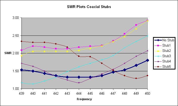
2 1 MHz in the 440 band. This gave a much smoother picture. I wasn t quite sure what affect the second conductor above the ¼ inch notch would have, so I did a little experimenting and just whacked it off. VSWR went immediately to 1.5 to 1. Theoretically it should have made the radiator look like a fat conductor effectively increasing bandwidth. The next step was to build the ¼ wavelength coax stub. Its purpose in life is to isolate the top section of the antenna electrically during 440 operations. It should present high impedance and be invisible at 444 MHz. Be very careful trimming this part as 1/8 inch can make a very large difference at 444 MHz. I used a velocity factor of.78 for RG-8X. for a length of 5.18 inches (Note: this is from the point where the shield is shorted to the center conductor to the end of the shield braid). Due to lots of experimenting back and forth, I ended up with a set of coax stubs in varying lengths and purposely cut some longer and others shorter than the calculated length. It was interesting how much these could affect the VSWR curve. Tests were made at 440 to 450 MHz adding just the coax stub and not the top section. Finally it was time to add the top section. Here I just added a 20 inch piece of stranded 12 gauge copper wire cut intentionally long. This time tuning was done at 146 MHz for a center frequency in the 2 meter band, cutting 1/8 inch at a time and watching the VSWR drop. Once the VSWR dips and starts to rise again, you have cut off too much wire. No worries though, crimp and solder a round terminal lug on the end to make up for the lost length and give yourself a method to hang the antenna. You can also adjust the feed point up or down slightly for lowest VSWR. Plotting all this data got old using a chart to look up VSWR each time. Here is a formula I found rooting around the web. Let Excel do the work Excel formula cell C4 is the reflected PWR and cell $D$1 is the forward PWR. =(1+SQRT(C4/$D$1))/(1-SQRT(C4/$D$1)) URL of the original article -
3 Below is an Excel chart plotting VSWR for 2 mtr and 440 operations. I compared the curves for a successfully built antenna with all ladder line and then my antenna variation with a single conductor radiating element. The all ladder line did prove to be more wide banded at 440 Mhz, but I achieved a slightly lower VSWR with the single conductor radiator design. Both worked equally well at 2 mtrs looking at the 2:1 VSWR. Mine was centered slightly higher in the band. Build two antennas and you will get two different VSWR plots. It takes patience and careful pruning to build one of these. You may want to consider different types of coax for your stub and feedline because of power handling capabilities and line loss, but don t forget to use the correct velocity factor. Feedline Velocity Power Loss Factor 400 MHz 100 RG-8X RG RG RG twin ladder.92 I used liquid tape and heat shrink to weather proof all bare connections. 73 s and good luck building. Steve, KM5HT
4
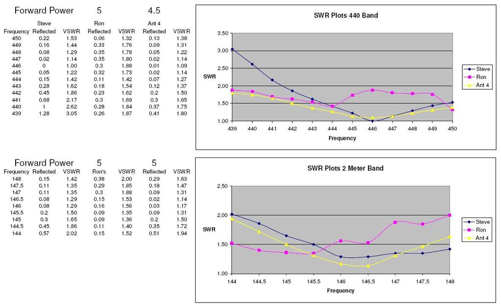
5 Revision: I still found myself with a piece of John s ladder line from the first antenna laying around. I couldn t just throw it away, so I decided to experiment a little more. This piece had the matching section cut at 18 ¼ inches, but the 444 MHz radiator was a bit short. I cut off the second conductor above the ¼ inch notch again, and extended the radiator. It s length ended up at 13 ½ inches, a bit longer than antenna 2. The coax stub was the same length and the upper part of 146 radiator was a bit shorter. The resulting SWR curves were an improvement over the last antenna. Lower SWR and more wide banded. I may just have to go back and do a bit more tweaking on the previous antennas. I also included the SWR plots using the different length coax stubs. I found that to be an interesting picture as well. Note: Antenna 4 was built from parts of antenna 1. It might be interesting to experiment some more with the length of the matching section to see what kind of results can be obtained. 73 Steve, KM5HT
6
The DBJ-1: A VHF-UHF Dual-Band J-Pole
 By Edison Fong, WB6IQN The DBJ-1: A VHF-UHF Dual-Band J-Pole Searching for an inexpensive, high-performance dual-band base antenna for VHF and UHF? Build a simple antenna that uses a single feed line for
Amateur Extra Manual Chapter 9.4 Transmission Lines
 9.4 TRANSMISSION LINES (page 9-31) WAVELENGTH IN A FEED LINE (page 9-31) VELOCITY OF PROPAGATION (page 9-32) Speed of Wave in a Transmission Line VF = Velocity Factor = Speed of Light in a Vacuum Question
TWO METER HOMEMADE SLIM JIM ANTENNA
 Gordon Gibby July 15, 2016 TWO METER HOMEMADE SLIM JIM ANTENNA WIRE: Start with a piece of solid #14 AWG household wire approximately 3 yards and 9 inches long (117 ) (It is easier to be a couple inches
Optimizing Your Stations Performance
 Optimizing Your Stations Performance A few hints / techniques, recommendations for getting the most RF out to the Antenna from your HF, VHF / UHF station. Tonights Presenters: Doug Theriault NO1D John
Cray Valley Radio Society. Real Life Wire Antennas
 Cray Valley Radio Society Real Life Wire Antennas 1 The basic dipole The size of an antenna is determined by the wavelength of operation In free space: ~3x10 8 m/s Frequency x Wavelength = Speed of Light,
A Stub Matched Lazy H for 17 M
 A Stub Matched Lazy H for 17 M Introduction The author has experimented with various configurations of the classic Lazy H antenna and a version optimised for operation on the 17 M band is shown in Figure
A Tri Band Antenna for 2 meters, 220 MHz, and 70cm Antenna Without Radials. By: Edison Fong (WB6IQN)
") A Tri Band Antenna for 2 meters, 220 MHz, and 70cm Antenna Without Radials By: Edison Fong (WB6IQN) Twenty years ago a single band handie talkie would have been adequate for emergency use since almost
A Tri Band Antenna for 2 meters, 220 MHz, and 70cm Antenna Without Radials By: Edison Fong (WB6IQN) Twenty years ago a single band handie talkie would have been adequate for emergency use since almost
J-Poles. Mythbusting J-Pole Antennas
 Mythbusting J-Pole Antennas For an antenna to work correctly, it must do two things well 1) Accept power from the feed line impedance match, SWR (ideally) 1:1 2) Radiate power in a pattern that is useful
Chapter 6 Antenna Basics. Dipoles, Ground-planes, and Wires Directional Antennas Feed Lines
 Chapter 6 Antenna Basics Dipoles, Ground-planes, and Wires Directional Antennas Feed Lines Some General Rules Bigger is better. (Most of the time) Higher is better. (Most of the time) Lower SWR is better.
Improved Ionospheric Propagation With Polarization Diversity, Using A Dual Feedpoint Cubical Quad Loop
 Improved Ionospheric Propagation With Polarization Diversity, Using A Dual Feedpoint Cubical Quad Loop by George Pritchard - AB2KC ab2kc@optonline.net Introduction This Quad antenna project covers a practical
A IVE-BAND, TWO-ELEMENT H QUAD
 A IVE-BAND, TWO-ELEMENT H QUAD Two quad designs are described in this article, both nearly identical. One was constructed by KC6T from scratch, and the other was built by Al Doig, W6NBH, using modified
L. B. Cebik, W4RNL. Basic Transmission Line Properties
 L. B. Cebik, W4RNL In the course of developing this collection of notes, I have had occasion to use and to refer to both series and parallel coaxial cable assemblies. Perhaps a few notes specifically devoted
General License Class Chapter 6 - Antennas. Bob KA9BHD Eric K9VIC
 General License Class Chapter 6 - Antennas Bob KA9BHD Eric K9VIC Learning Objectives Teach you enough to get all the antenna questions right during the VE Session Learn a few things from you about antennas
Installation Instructions Hustler 6-BTV Trap Vertical
 Installation Instructions Hustler 6-BTV Trap Vertical ASSEMBLY 1. Check the package contents against the parts list on page 2. 2. WARNING. Installation of this product near power lines is dangerous. For
BUILD A HIGH PERFORMANCE TWO ELEMENT TRI-BAND CUBICAL QUAD. By Bob Rosier K4OCE INTRODUCTION THEORY AND GENERAL INFORMATION
 BUILD A HIGH PERFORMANCE TWO ELEMENT TRI-BAND CUBICAL QUAD INTRODUCTION By Bob Rosier K4OCE Lots of DX can be worked with a dipole at the QRP level, however, a beam will obviously give you additional gain
Milton Keynes Amateur Radio Society (MKARS)
") Milton Keynes Amateur Radio Society (MKARS) Intermediate Licence Course Feeders Antennas Matching (Worksheets 31, 32 & 33) MKARS Intermediate Licence Course - Worksheet 31 32 33 Antennas Feeders Matching
Milton Keynes Amateur Radio Society (MKARS) Intermediate Licence Course Feeders Antennas Matching (Worksheets 31, 32 & 33) MKARS Intermediate Licence Course - Worksheet 31 32 33 Antennas Feeders Matching
The Fabulous Dipole. Ham Radio s Most Versatile Antenna
 The Fabulous Dipole Ham Radio s Most Versatile Antenna 1 What is a Dipole? Gets its name from its two halves One leg on each side of center Each leg is the same length It s a balanced antenna The voltages
The DBJ-2: A Portable VHF-UHF Roll-Up J-pole Antenna for Public Service
 The DBJ-2: A Portable VHF-UHF Roll-Up J-pole Antenna for Public Service WB6IQN reviews the theory of the dual band 2 meter / 70 cm J-pole antenna and then makes detailed measurements of a practical, easy
MFJ-219/219N 440 MHz UHF SWR Analyzer TABLE OF CONTENTS
 MFJ-219/219N 440 MHz UHF SWR Analyzer TABLE OF CONTENTS Introduction...2 Powering The MFJ-219/219N...3 Battery Installation...3 Operation Of The MFJ-219/219N...4 SWR and the MFJ-219/219N...4 Measuring
Amateur Radio (G3TXQ) - Folded dipoles
 - Folded dipoles") A. Introduction Amateur Radio (G3TXQ) - Folded dipoles A recent interest in "bent" half-wave dipoles led me to look into the theory of the classic Folded Dipole (FD) in some depth. Dipoles bent into a
A. Introduction Amateur Radio (G3TXQ) - Folded dipoles A recent interest in "bent" half-wave dipoles led me to look into the theory of the classic Folded Dipole (FD) in some depth. Dipoles bent into a
Installation Instructions Hustler 6-BTV Trap Vertical
 Installation Instructions Hustler 6-BTV Trap Vertical ASSEMBLY 1. Check the package contents against the parts list on page 2. 2. WARNING. Installation of this product near power lines is dangerous. For
Adjust Antenna Tuners Antenna Measurements Capacitor Measurement Measure Feed Point Impedance Measure Ground Loss Inductor Measurement
 The Micro908 antenna analyzer is an extremely useful instrument to have around the ham shack or homebrewer s workbench. This section describes the basic uses, as well as some advanced techniques for which
Least understood topics by most HAMs RF Safety Ground Antennas Matching & Feed Lines
 Least understood topics by most HAMs RF Safety Ground Antennas Matching & Feed Lines Remember this question from the General License Exam? G0A03 (D) How can you determine that your station complies with
Hardware Store 40m Magnetic Loop Antenna for Regional and EMCOM Use. Richard Bono NO5V. QST Antenna Design Competition 80 through 10 meter entry
 Hardware Store 40m Magnetic Loop Antenna for Regional and EMCOM Use Richard Bono NO5V QST Antenna Design Competition 80 through 10 meter entry Overview: This describes a field deployable magnetic loop
The first thing to realize is that there are two types of baluns: Current Baluns and Voltage Baluns.
 Choosing the Correct Balun By Tom, W8JI General Info on Baluns Balun is an acronym for BALanced to UNbalanced, which describes certain circuit behavior in a transmission line, source or load. Most communications
The Principle V(SWR) The Result. Mirror, Mirror, Darkly, Darkly
 The Result. Mirror, Mirror, Darkly, Darkly") The Principle V(SWR) The Result Mirror, Mirror, Darkly, Darkly 1 Question time!! What do you think VSWR (SWR) mean to you? What does one mean by a transmission line? Coaxial line Waveguide Water pipe Tunnel
The Principle V(SWR) The Result Mirror, Mirror, Darkly, Darkly 1 Question time!! What do you think VSWR (SWR) mean to you? What does one mean by a transmission line? Coaxial line Waveguide Water pipe Tunnel
Technician Licensing Class T9
 Technician Licensing Class T9 Amateur Radio Course Monroe EMS Building Monroe, Utah January 11/18, 2014 January 22, 2014 Testing Session Valid dates: July 1, 2010 June 30, 2014 Amateur Radio Technician
Welcome to AntennaSelect Volume 10 May Optimizing VHF (Band III) Batwing antennas - Part 2
 Batwing antennas - Part 2") Welcome to AntennaSelect Volume 10 May 2014 Welcome to Volume 10 of our newsletter, AntennaSelect TM. Each month we will be giving you an under the radome look at antenna and RF technology. If there are
Welcome to AntennaSelect Volume 10 May 2014 Welcome to Volume 10 of our newsletter, AntennaSelect TM. Each month we will be giving you an under the radome look at antenna and RF technology. If there are
A short, off-center fed dipole for 40 m and 20 m by Daniel Marks, KW4TI
 A short, off-center fed dipole for 40 m and 20 m by Daniel Marks, KW4TI Version 2017-Nov-7 Abstract: This antenna is a 20 to 25 foot long (6.0 m to 7.6 m) off-center fed dipole antenna for the 20 m and
The EMCOMM Easytenna
 The EMCOMM Easytenna This document will detail how to build an easy to install multiband dipole type antenna for emergency communications using the NVIS propagation mode. History The NVIS mode is one in
"Banana", a Half Wave End-Fed Choked Coax Antenna by Callum McCormick, M0MCX
 "Banana", a Half Wave End-Fed Choked Coax Antenna by Callum McCormick, M0MCX Also know as - and similar to: Sleeve Dipole / Flowerpot Antenna The Sleeve dipole has traditionally been used by VHF antenna
Newcomers And Elmers Net: Wire Antennas Robert AK3Q
 Newcomers And Elmers Net: Wire Antennas 02-07-16 Robert AK3Q Wire antennas represent one of the greatest values in the radio hobby world. For less than the cost of a good meal out on the town you can buy
WRAPS Rotor Enhancements Add a Second Beam and Circular Polarization
 WRAPS Rotor Enhancements Add a Second Beam and Circular Polarization Mark Spencer, WA8SME (mspencer@arrl.org) ARRL Education and Technology Program Part 1: Tricked-Out WRAPS Satellite Antenna Rotator Adds
The 2 meter Hentenna
 The 2 meter Hentenna (No Tuning Required!) While browsing through my new copy of Simple and Fun Antennas for Hams one day in the Spring of 2003, I discovered an interesting looking design, with an interesting
Alpha Delta Communications, Inc. Model DX-OCF Off-Center-Fed 7 Band Antenna
 Alpha Delta Communications, Inc. Model DX-OCF Off-Center-Fed 7 Band Antenna 75/80, 40, 20, 17, 12, 10, and 6 meters (50.0-51.0 MHz) NO TUNER REQUIRED! Installation Instructions One leg is 45 ft., the other
The J-Pole Antenna. Gary Wescom
 The J-Pole Antenna Gary Wescom - 2018 Much has been written about the J-Pole antenna. A simple Google search will net days worth of reading material on the subject. That would tend to indicate this paper
A multi-band wire antenna that performs exceptionally well even though it confounds antenna modeling software
 A multi-band wire antenna that performs exceptionally well even though it confounds antenna modeling software Click FAQ to read a list of frequently asked questions and answers about the W5GI Mystery Antenna.
DO NOT COPY. Basic HF Antennas. Bill Shanney, W6QR
 Basic HF Antennas Bill Shanney, W6QR When I was first licensed in 1961 I didn t know much about antennas. I put up the longest wire that fit on my parent s lot at the lofty height of 25 and fed it with
Tuning a 160M full sized vertical with strong AM broadcast RF present on the antenna. Jay Terleski, WX0B
 Tuning a 160M full sized vertical with strong AM broadcast RF present on the antenna. Jay Terleski, WX0B I often get asked about how to match a ¼ WL vertical to a 50 ohm transmission line and what to do
THE REAL SWR PAGE! Used with the kind permission of Stephen C. Ward, WC7I
 This page contains lots of material. Expect a long, facinating read! THE REAL SWR PAGE! Used with the kind permission of Stephen C. Ward, WC7I www.wc7i.com This page is in 2 parts, all about... Part 1.
Antenna Design for FM-02
 Antenna Design for FM-02 I recently received my FM-02 FM transmitter which I purchased from WLC. I researched the forum on what antennas where being used by the DIY community and found a nice write-up
Transmission lines. Characteristics Applications Connectors
 Transmission lines Characteristics Applications Connectors Transmission Lines Connect They allow us to conduct RF Signals between our station components, they connect: Transceivers Antennas Tuners Amplifiers
THE HENTENNA RE-VISITED
 THE HENTENNA RE-VISITED "The following article has been re-edited for the English language from the Japanese site. Minor errors and corrections have been made." The Hentenna was developed by Japanese 6
Transmission Lines and SWR
 THE HAM S WIRELESS WORKBENCH PRACTICAL TECHNOLOGY FROM THE HAM WORLD BY WARD SILVER N0AX hwardsil@gmail.com Transmission Lines and SWR What s going on in that cable, anyway? When shown an early radio station,
End Fed Half Wave Antenna Coupler
 End Fed Half Wave Antenna Coupler The finished End Fed Half Wave antenna coupler. Centre fed half wave dipoles make great, simple and effective antennas for the HF bands. Sometimes however, the centre
1) Transmission Line Transformer a. First appeared on the scene in 1944 in a paper by George Guanella as a transmission line transformer, the 1:1
 Transmission Line Transformer a. First appeared on the scene in 1944 in a paper by George Guanella as a transmission line transformer, the 1:1") 1) Transmission Line Transformer a. First appeared on the scene in 1944 in a paper by George Guanella as a transmission line transformer, the 1:1 Guanella Balun is the basic building Balun building block.
1) Transmission Line Transformer a. First appeared on the scene in 1944 in a paper by George Guanella as a transmission line transformer, the 1:1 Guanella Balun is the basic building Balun building block.
4/25/2012. Supplement T9. 2 Exam Questions, 2 Groups. Amateur Radio Technician Class T9A: T9A: T9A: T9A:
 Amateur Radio Technician Class Element 2 Course Presentation ti ELEMENT 2 SUB-ELEMENTS Technician Licensing Class Supplement T9 Antennas, Feedlines 2 Exam Questions, 2 Groups T1 - FCC Rules, descriptions
NVIS, Another Look. Tom Sanders, W6QJI Ed Bruette, N7NVP
 NVIS, Another Look Tom Sanders, W6QJI Ed Bruette, N7NVP Regional Communications N.V.I.S. Near Vertical Incidence Skywave What is NVIS? Near Vertical Incident Skywave Cloud Warmer Propagation Theory NVIS
MFJ-208 VHF SWR Analyzer
 MFJ-208 VHF SWR Analyzer Thank you for purchasing the MFJ-208 VHF SWR Analyzer. The MFJ-208 gives you a direct readout of your antenna's SWR without the need for formulas or indirect readings. The MFJ-
The W3FF Portable Dipole
 The W3FF Portable Dipole This is the antenna I designed for my 'walking portable' station. It is a dipole constructed out of the plastic plumbing pipe CPVC. There are telescoping whips at the ends of each
Observations Regarding Selection and Installation of Masthead VHF whip antennas:
 VHF AIS masthead antenna and coax installation, selection, and test. Stan Honey and Dan Jowett 28 August 2018 Observations Regarding Selection and Installation of Masthead VHF whip antennas: Whip Antennas
Connecting Your Rig To The Aether
 Connecting Your Rig To The Aether 1 Ward Harriman (AE6TY) Pacificon 18 1: of course, there is no Aether! Presentation Goals Review a common design to reinforce forgotten knowledge. Use that design to demonstrate
Antenna? What s That? Chet Thayer WA3I
 Antenna? What s That? Chet Thayer WA3I Space: The Final Frontier Empty Space (-Time) Four dimensional region that holds everything Is Permeable : It requires energy to set up a magnetic field within it.
Feed Line Currents for Neophytes.
 Feed Line Currents for Neophytes. This paper discusses the sources of feed line currents and the methods used to control them. During the course of this paper two sources of feed line currents are discussed:
ANTENNAS Wires, Verticals and Arrays
 ANTENNAS Wires, Verticals and Arrays Presented by Pete Rimmel N8PR 2 1 Tonight we are going to talk about antennas. Anything that will conduct electricity can be made to radiate RF can be called an antenna.
ANOTHER MULTIBAND WIRE ANTENNA
 ANOTHER MULTIBAND WIRE ANTENNA Above The multiband long wire with balun (cover is off) by Ron VK3AFW. I wanted to build a simple wire antenna dedicated to 30 m and 17m for operation during the 2015 ILLW
RigExpert AA-170 Antenna Analyzer (0.1 to 170 MHz) User s manual
 User s manual") RigExpert AA-170 Antenna Analyzer (0.1 to 170 MHz) User s manual Table of contents 1. Description... 3 2. Specifications... 4 3. Precautions... 5 4. Operation... 6 4.1. Preparation for use... 6 4.2. Turning
RigExpert AA-170 Antenna Analyzer (0.1 to 170 MHz) User s manual Table of contents 1. Description... 3 2. Specifications... 4 3. Precautions... 5 4. Operation... 6 4.1. Preparation for use... 6 4.2. Turning
Portable Magnetic Loop Antenna. KG5EAO Rick Bono
 Portable Magnetic Loop Antenna KG5EAO Rick Bono April 2, 2016 Overview Develop a Portable magnetic loop antenna for use on HF bands running QRP. Portable and easy to deploy Ideally run on the 40m through
Emergency Antennas. Presented by Ham Hilliard W4GMM
 Emergency Antennas Presented by Ham Hilliard W4GMM Dipole antenna Vertical antenna Random wire antenna Dipole antenna The half wave dipole antenna consists of a conductive wire or rod that is half the
SOME USES FOR RF1,RF5 and VA1 ANALYSTS. SWR Measurement
 SOME USES FOR RF1,RF5 and VA1 ANALYSTS THE HANDIEST INSTRUMENTS IN DECADES! When you put up an antenna in the the old days, it could be a real struggle. The only way to tell if it was tuned to the right
EE 172 Final Project Report. 915 MHz Cantenna and Patch Antennas Design. By: Sawson Teheri Jared Buckley Ramon Alvarado
 EE 172 Final Project Report 915 MHz Cantenna and Patch Antennas Design By: Sawson Teheri Jared Buckley Ramon Alvarado May 25, 2004 Abstract: A 915 MHz antennas will be designed, constructed, measured and
Cushcraft. Amateur Radio Antennas LFA-6M5EL. 6 Meter 5 Element Loop Feed Antenna INSTRUCTION MANUAL
 Cushcraft Amateur Radio Antennas LFA-6M5EL 6 Meter 5 Element Loop Feed Antenna INSTRUCTION MANUAL CAUTION: Read All Instructions Before Operating Equipment VERSION 1A Cushcraft Amateur Radio Antennas 308
VHF/UHF Dual Band J-Pole. By: Ed Fong WB6IQN
 VHF/UHF Dual Band J-Pole By: Ed Fong WB6IQN email: edison_fong@hotmail.com ARRL VHF/UHF Antenna Classics ARRL Vol. 8 Antenna Compendium ARRL Vol. 3 Antenna Compendium QST March 2007 QST February 2003 QST
Technician License Course Chapter 4. Lesson Plan Module 9 Antenna Fundamentals, Feed Lines & SWR
 Technician License Course Chapter 4 Lesson Plan Module 9 Antenna Fundamentals, Feed Lines & SWR The Antenna System Antenna: Transforms current into radio waves (transmit) and vice versa (receive). Feed
Transmission lines carry RF
 Transmission Line asics Technical techniques: primer for transmission lines Part I n understanding of transmission lines and tips on using them as transformers and filters can help techs properly configure
Technician License. Course
 Technician License Course Technician License Course Chapter 4 Lesson Plan Module - 10 Practical Antennas The Dipole Most basic antenna The Dipole Most basic antenna The Dipole Total length is ½ wavelength
The quality you expect at the price you want to pay. Available at: 1 (888) (866)
 (866)") The quality you expect at the price you want to pay Available at: www.wirelessource.ca 1 (888) 430-0660 1 (866) 244-4844 October 2014 VHF Mobile Antennas... P1-5 UHF Mobile Antennas... P6-9 CB Mobile Antennas...
The quality you expect at the price you want to pay Available at: www.wirelessource.ca 1 (888) 430-0660 1 (866) 244-4844 October 2014 VHF Mobile Antennas... P1-5 UHF Mobile Antennas... P6-9 CB Mobile Antennas...
Array Solutions OCF Series Dipoles
 OCF Series Dipoles Fig 1 Thank you and congratulations on your purchase of the, Off- Center Fed HF Dipole Antenna System. This antenna was built with the same quality workmanship and attention to detail
Technician Licensing Class. Antennas
 Technician Licensing Class Antennas Antennas A simple dipole mounted so the conductor is parallel to the Earth's surface is a horizontally polarized antenna. T9A3 Polarization is referenced to the Earth
INSTRUCTION MANUAL. Specifications Mechanical. 1 5/8 to 2 1/16 O.D. (41mm to 52mm)
") 308 Industrial Park Road Starkville, MS 39759 USA Ph: (662) 323-9538 FAX: (662) 323- General Description Model VB-25FM 2-Meter 5 Elements Beam INSTRUCTION MANUAL This antenna is a 5-element, 2-meter beam
308 Industrial Park Road Starkville, MS 39759 USA Ph: (662) 323-9538 FAX: (662) 323- General Description Model VB-25FM 2-Meter 5 Elements Beam INSTRUCTION MANUAL This antenna is a 5-element, 2-meter beam
20m G4BUD Mobile Whip
 This particular antenna was built specifically to take on holiday to Fuerteventura in the Canary Islands, after it was originally tested from an inland site in the UK. Amongst my first contacts using the
N5PUV s 4 Band Fan Dipole Experiment. Using the New SRI (Stanford Research Institute) Method
 Method") N5PUV s 4 Band Fan Dipole Experiment Using the New SRI (Stanford Research Institute) Method Goals of Experiment Develop a Multi-band Antenna that does NOT require a tuner Build using the new, easier tuning
N5PUV s 4 Band Fan Dipole Experiment Using the New SRI (Stanford Research Institute) Method Goals of Experiment Develop a Multi-band Antenna that does NOT require a tuner Build using the new, easier tuning
Technician License. Course
 Technician License Course Technician License Course Chapter 4 Lesson Plan Module - 9 Antenna Fundamentals Feed Lines & SWR The Antenna System The Antenna System Antenna: Transforms current into radio waves
Portable or Emergency VHF Antennas Paul R. Jorgenson KE7HR
 For emergency or public service events it is often necessary to have more antenna than the rubber duck on your handheld VHF radio. Nearly ANY external antenna will provide more coverage for your handheld
TS-930: Installing the Inrad Roofing Filter Mod
 TS-930: Installing the Inrad Roofing Filter Mod The TS-930 roofing filter mod consists of a 6 pole, 4 to 5 khz wide filter followed by a high dynamic range, feedback amplifier. The amplifier provides enough
I recently came across a No-Counterpoise antenna described by designed by Peter Millis M3KXZ and based on an original design by K9ESE.
 M3KXZ 'no counterpoise' antenna I recently came across a No-Counterpoise antenna described by designed by Peter Millis M3KXZ and based on an original design by K9ESE. Details of the antenna can be found
The Amazing MFJ 269 Author Jack Tiley AD7FO
 The Amazing MFJ 269 Author Jack Tiley AD7FO ARRL Certified Emcomm and license class Instructor, Volunteer Examiner, EWA Technical Coordinator and President of the Inland Empire VHF Club What Can be Measured?
MFJ-249B HF/VHF SWR ANALYZER
 TABLE OF CONTENTS MFJ-249B... 2 Introduction... 2 Powering The MFJ-249B... 3 Battery Installation... 3 Alkaline Batteries... 3 NiCd Batteries... 4 Power Saving Mode... 4 Operation Of The MFJ-249B...5 SWR
Lightning Strikes. Presented to the Greater Norwalk Amateur Radio Corporation Inc. February 8, 2017 Steven M. Simons W1SMS
 Lightning Strikes Presented to the Greater Norwalk Amateur Radio Corporation Inc. February 8, 2017 Steven M. Simons W1SMS ARRL CT State Technical Coordinator The Power of Lightning What is a Ground? Design
02680SX Series UHF Mount Dipole Array Series
 02680SX Series UHF Mount Dipole Array Series Page 1 of 11 Description The 02680SX series antennas are 0dB, 3dB and 6dB Gain, Stainless Steel Side Mount Dipole Array antennas, for use in the Commercial
ELECTRICALLY LONG NGP ANTENNA SYSTEMS
 The K-8NGP is a tuned coaxial cable assembly that can only be used with special no-groundplane antennas. This coaxial cable will not work with any standard ground plane dependent CB antenna. We offer it
VHF and UHF Antennas for QRP Portable Operation. Prepared for the QRP forum at Pacificon2011 by KK6MC James Duffey October 15, 2011
 VHF and UHF Antennas for QRP Portable Operation Prepared for the QRP forum at Pacificon2011 by KK6MC James Duffey October 15, 2011 Overview Get on the air from portable locations with simple and effective
MFJ-835 RF Ammeter. Introduction. Uses
 MFJ-835 RF Ammeter Introduction Congratulations on purchasing the MFJ-835 Balanced Line RF Ammeter. The MFJ-835 is designed for measuring balanced RF feedline current on 1.8-30 MHz while having low interaction
USER GUIDE V1.1 October 11, 2013
 Alpha Antenna Model Loop Jr Alpha Loop Jr Antenna 15, 17, 20, 30, & 40 Meters 10 Watts (15 Watts PEP) USER GUIDE V1.1 October 11, 2013 Page 1 Introduction The ultra high-performance (High Q) Alpha Loop
Basic Wire Antennas. Part II: Loops and Verticals
 Basic Wire Antennas Part II: Loops and Verticals A loop antenna is composed of a single loop of wire, greater than a half wavelength long. The loop does not have to be any particular shape. RF power can
Thank you for purchasing the Ameritron SDA-100 Antenna
 Thank you for purchasing the Ameritron SDA-100 Antenna When properly installed this antenna will provide continuous coverage of 3.5 to 30 MHz with a 6' whip, also 6.0 to 60 MHz without a whip. Installation
ANTENNAS. I will mostly be talking about transmission. Keep in mind though, whatever is said about transmission is true of reception.
 Reading 37 Ron Bertrand VK2DQ http://www.radioelectronicschool.com ANTENNAS The purpose of an antenna is to receive and/or transmit electromagnetic radiation. When the antenna is not connected directly
MFJ-834 RF Ammeter. Introduction. Uses
 MFJ-834 RF Ammeter Introduction Congratulations on purchasing the MFJ-834 RF Ammeter. The MFJ-834 is designed for measuring in-line RF feedline current on 1.8-30 MHz while having low interaction on the
FCC Technician License Course
 FCC Technician License Course 2014-2018 FCC Element 2 Technician Class Question Pool Presented by: Tamiami Amateur Radio Club (TARC) WELCOME To the third of 4, 3-hour classes presented by TARC to prepare
TBARC Programs Antenna Modeling with 4NEC2. By Randy Rogers AD7ZU 2010
 TBARC Programs Antenna Modeling with 4NEC2 By Randy Rogers AD7ZU 2010 Getting Started 4NEC2 is a completely free windows based tool suite to aid in the design and optimization of antenna systems 4NEC2
RF Transmission Lines & SWR
 RF Transmission Lines & SWR After installing the Antenna and finding a place for the Transceiver, you must connect the two together and the Antenna is usually located at some distance away from the Transceiver.
Array Solutions Four Square Array Manual and User s Guide
 Array Solutions Four Square Array Manual and User s Guide Array Solutions Four Square Array Pattern Steering System Congratulations! You have selected one of the finest phased array steering systems made.
Transmission Lines As Impedance Transformers
 Transmission Lines As Impedance Transformers Bill Leonard N0CU 285 TechConnect Radio Club 2017 TechFest Topics Review impedance basics Review Smith chart basics Demonstrate how antenna analyzers display
EZNEC Primer. Introduction:
 EZNEC Primer Introduction: This document was written to cover the very basic functions of EZNEC. It's primarily geared to the use of EZNEC demo programs, specifically the Version 5 demo. While more elaborate
20 meter bandstop filter notes
 1 Introduction 20 meter bandstop filter notes Kevin E. Schmidt, W9CF 6510 S. Roosevelt St. Tempe, AZ 85283 USA A shorted half-wavelength stub cut for 20 meters acts as a bandstop filter for 10 and 20 meters,
Pacific Antenna 20 and 40M Lightweight Dipole Kit
 Pacific Antenna 20 and 40M Lightweight Dipole Kit Antenna diagram showing configuration and lengths when assembled 7 8 16 9 16 9 Description The Pacific Antenna lightweight dual band dipole kit provides
MAGNETIC LOOP SYSTEMS SIMPLIFIED
 MAGNETIC LOOP SYSTEMS SIMPLIFIED By Lez Morrison VK2SON Many articles have been published and made available on websites recently. Unfortunately they have tended to make construction sound complicated
Amateur Radio License. Propagation and Antennas
 Amateur Radio License Propagation and Antennas Todays Topics Propagation Antennas Propagation Modes Ground wave Low HF and below, ground acts as waveguide Line-of-Sight (LOS) VHF and above, radio waves
AD5X. Low Cost HF Antennas & Accessories. Phil Salas - AD5X Phil Salas AD5X. Richardson, Texas
 Low Cost HF Antennas & Accessories Phil Salas - AD5X ad5x@arrl.net PVC Tubing PVC pipe: Considers the inside diameter (ID) of the pipe. For PVC pipe (schedule 40): 1/2" PVC pipe has an ID of 0.6" and an
Performance Predicted by YAGI-CAD
 1 of 7 11/16/2010 2:02 PM Joe Leggio WB2HOL Description This antenna evolved during my search for a beam with a really great front-to-back ratio to use in hidden transmitter hunts. This design exhibits