NVIS, Another Look. Tom Sanders, W6QJI Ed Bruette, N7NVP
|
|
|
- Quentin Jones
- 5 years ago
- Views:
Transcription

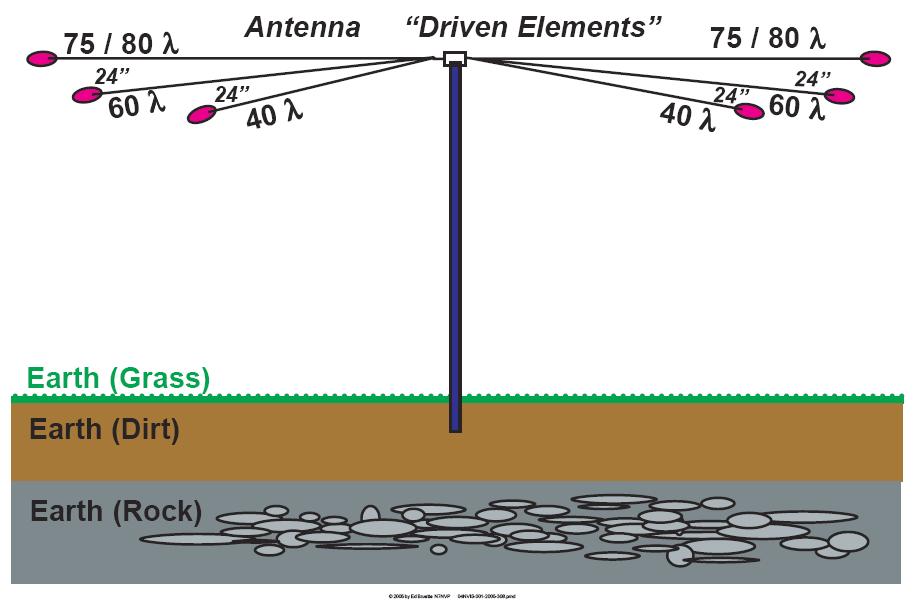
1 NVIS, Another Look Tom Sanders, W6QJI Ed Bruette, N7NVP
2 Regional Communications N.V.I.S. Near Vertical Incidence Skywave
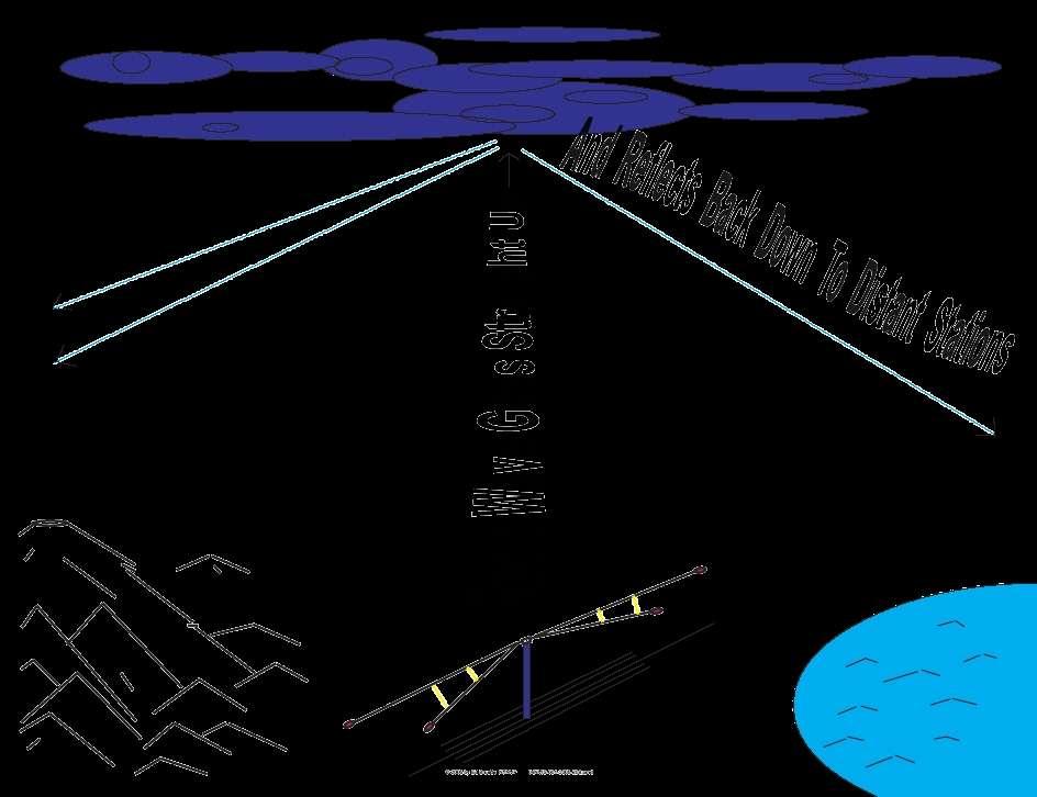
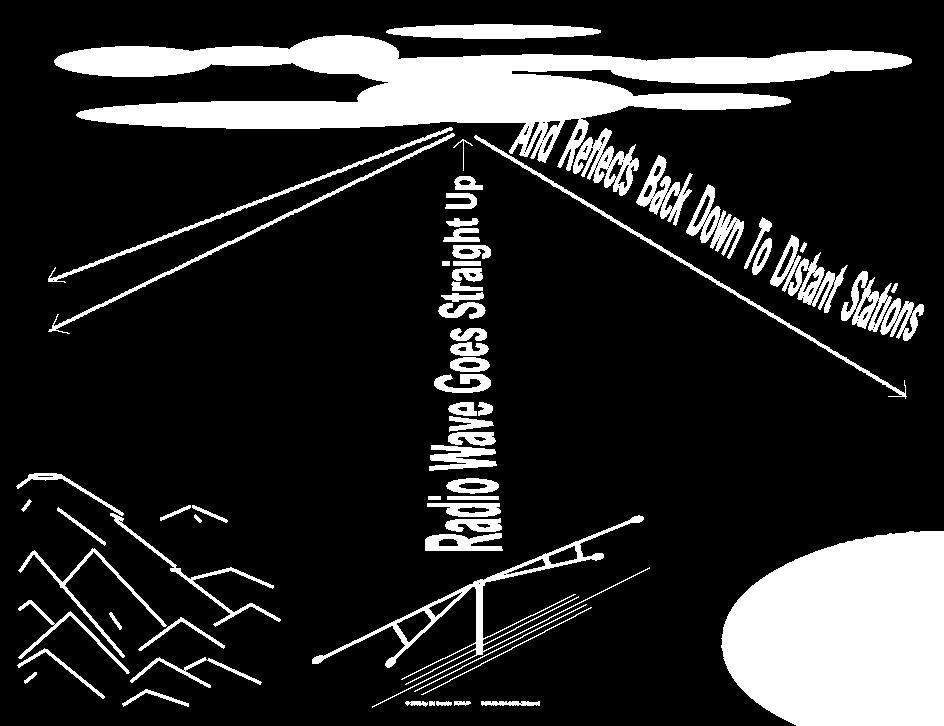
3 What is NVIS? Near Vertical Incident Skywave Cloud Warmer
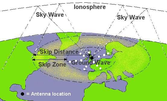
4 Propagation Theory

5 NVIS Effect

6 300 Mile Coverage
7
8
9
10
11
12
13 5/8 Wave 75 Meter Vertical Radiation Pattern
14

15 75 Meter SWR
16 Bandwidth 75 Meters : dip :1
17 75 Meter Vertical Radiation Pattern
18 60 Meter SWR
19 Bandwidth 60 Meters : dip :1
20 60 Meter Vertical Radiation Pattern

21 40 Meter SWR
22 Bandwidth 40 Meters : dip :1
23 40 Meter Vertical Radiation Pattern
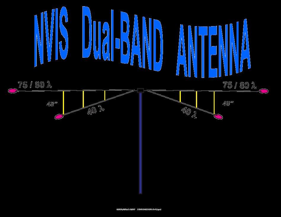
24 Dual Band Yes; you can remove the 60 Meter elements!
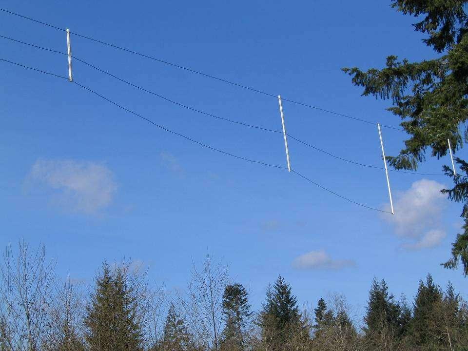
25
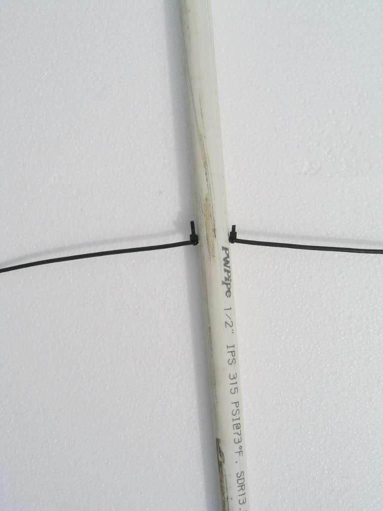
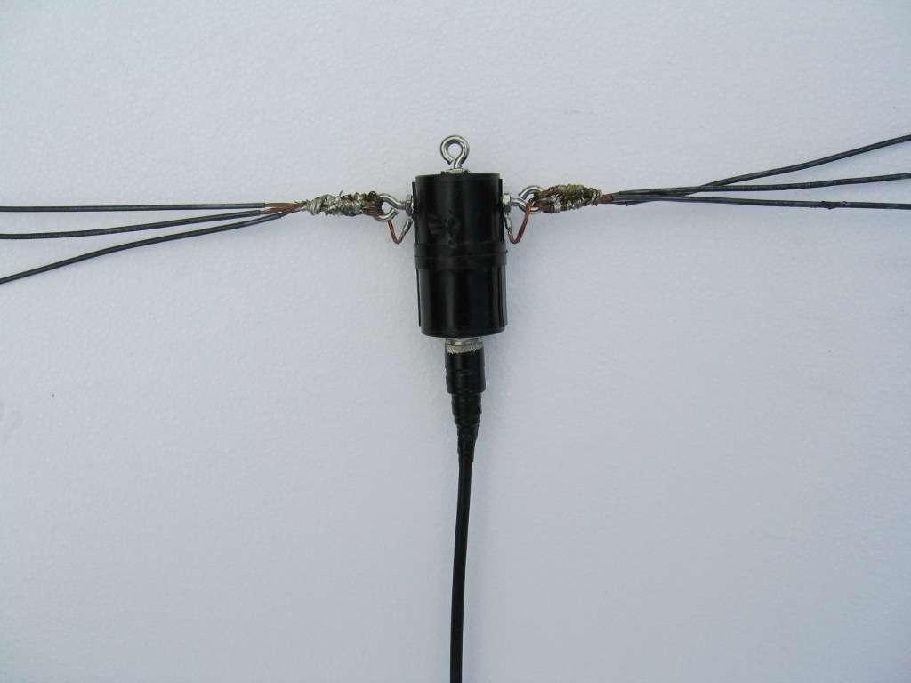
26 75 Meter SWR
27 75 Meter Vertical Radiation Pattern
28 40 Meter Dual Band SWR
29 40 Meter Vertical Radiation Pattern

30 Depth of Current Penetration
31
32 How It Went Together Materials Construction Modifications

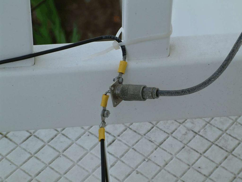
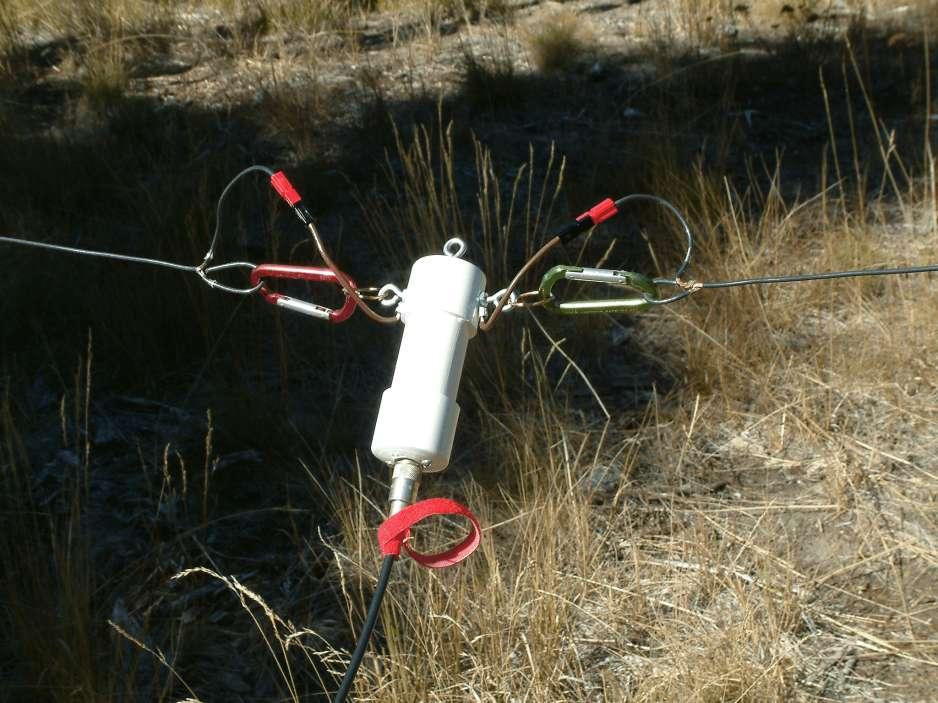
33 Parts List 1 - Feed point - 50 Ohm #14 insulated stranded wire ½ x 10 PVC cut to length 2 Insulators Tie wraps 3/16 rope cut to length Coax to the shack
34
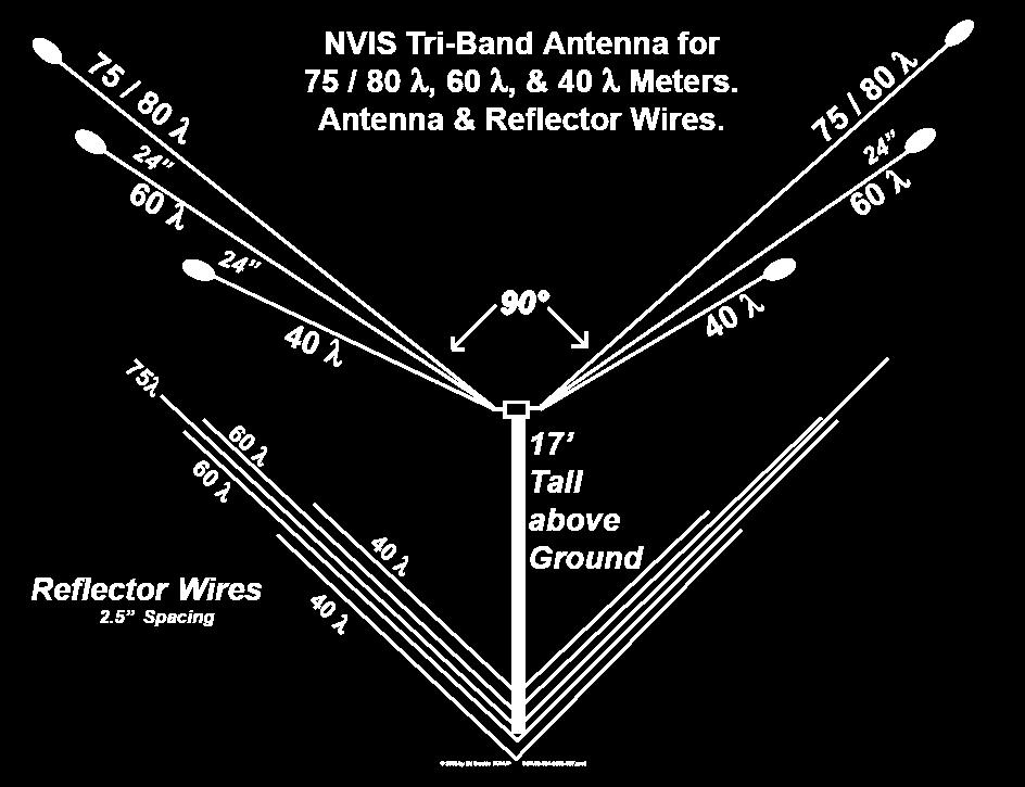
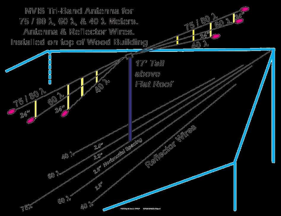
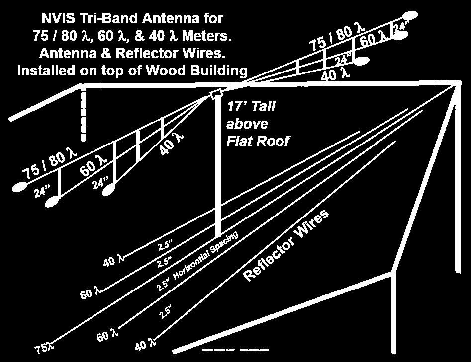
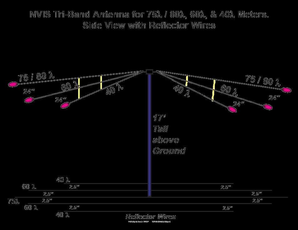
35 Spreader Lengths Next to center insulator 2 nd from center insulator End of 40 M element End of 60M element Another spreader could be used between the center insulator and the end of the 40M element
36
37 Element Lengths 75 Mtr legs = ft 60 Mtr legs = 45.4 ft 40 Mtr legs = ft Prune these lengths to meet your ground conditions

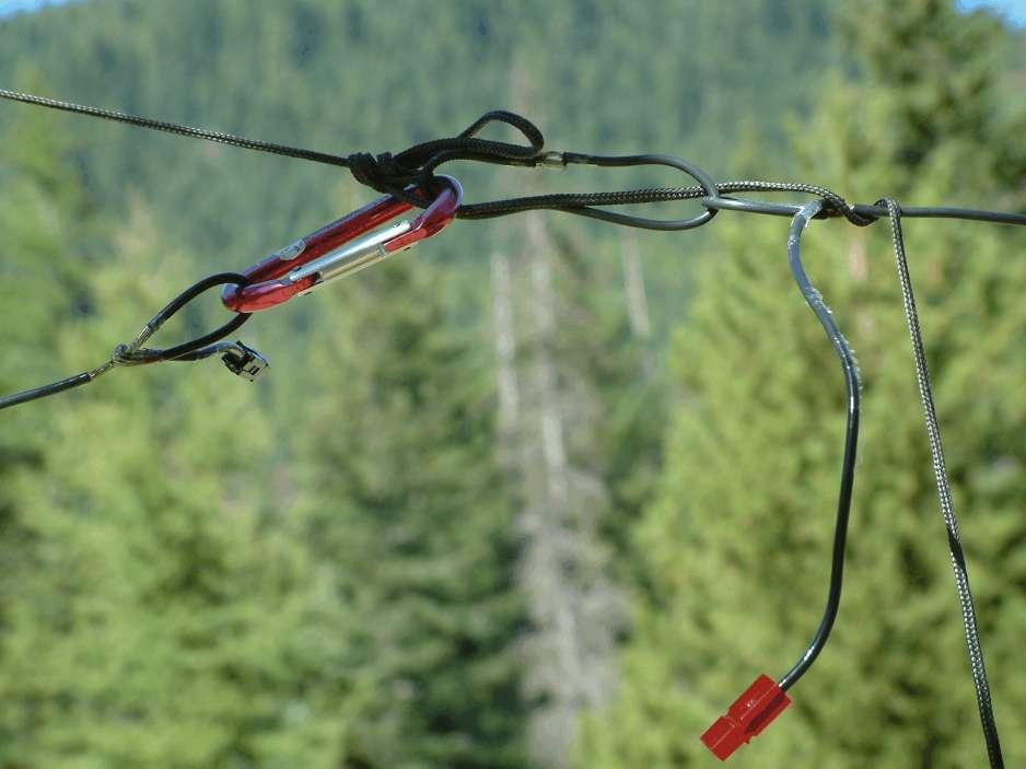
38 40 Meter Tension

39 Tensioning method for 40M

40 Spreader keepers
41

42 UV resistant line 60 Meter tension

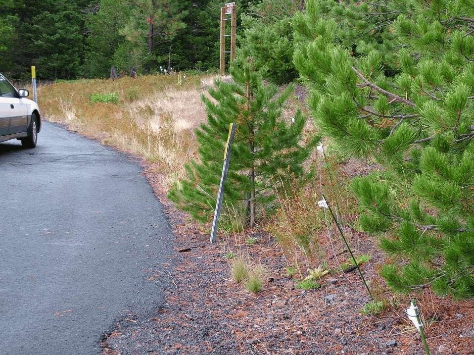
43 60 Meter Tension
44 Beamwidth 75 Mtrs 60 Mtrs 40 Mtrs 38 deg. To 142 deg deg To deg. 34 deg. To 146 deg.

45 Night Time Ionosphere (300 mi.)
46 Hints & tips Solder wires at the feed point Solder feed point pigtail to all other wires Dipole insulator has an eye bolt in the top for suspension from a tree or skyhook Coax should be perpendicular to the antenna
47

48 Choke balun 18 coiled 9-10 turns
49 Hints & tips (cont.) Ground conditions will drive element lengths Wet vs.. dry Use an antenna analyzer!!! Tune 75M first, then 60 then 40M There is interaction between the 60 & 40 meter elements
50 Reflectors Ground wires laid directly under the antenna 5 Total! 1 on 75M and 2 each on 60 & 40M Spacing is important M on either side of 75M & 40M on the outside of 60M
51
52 Tri-band Reflector Lengths 75M 65 60M M
53
54
55
56 Dual Band Element Lengths 75 Mtr legs = 59.7 ft 40 Mtr legs = ft Prune these lengths to meet your ground conditions
57 Dual Band Reflector Lengths 75M M
58
59 60 Meter Considerations USB 2.8 khz bandwidth limitation 5 Channels (Window freq khz) 100W ERP limitation Antenna gain Feedline loss QST Feb or ARRL FAQ
60 Regional 60 Meter Agreement 5405 Nation/International 5373 Washington 5368 Idaho 5348 Montana/Oregon 5332 Regional coordination between states/sections
61
62 NVIS Antennas are nondirectional, Antennas designed for High angle, beamwidth may be 30 degrees or more, greatly determined by antenna height Refracted back in circular pattern Radius depends on strength and D/E layer absorption Ground wave can help/hinder NVIS skywave, due to phase relationship

63 Omni Pattern
64
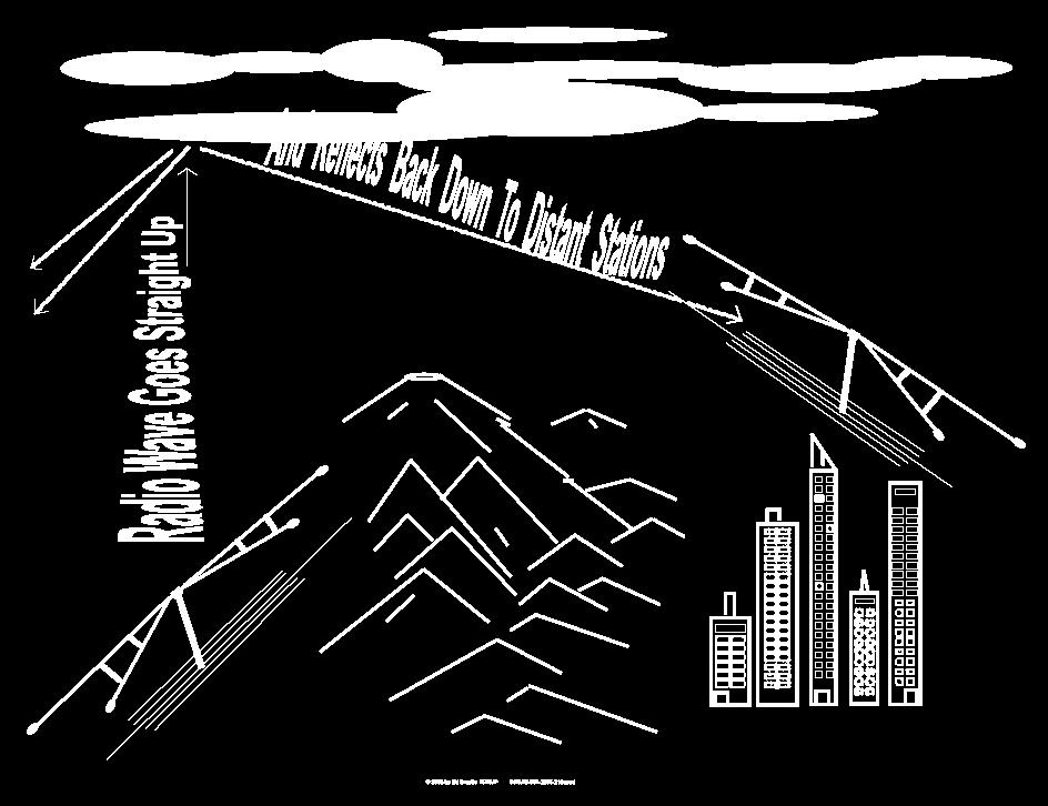
65 NVIS Advantages 1.Covers area normally in skip zone 2.No infrastructure repeaters, satellites 3.Pure NVIS relatively free from fading 4.Antennas are low, Simple dipoles work well Fast erection with small team or 1 person
66 NVIS Advantages 5.Low areas, valleys, gulley, ravines are not a problem 6.Path up and down is short and direct, lower path loss from D layer & other factors 7.NVIS techniques can dramatically reduce noise and interference, S/N ratio improved 8.Works well with low power (S/N ratio & low path loss) 9.Antenna quite easily camouflaged (Military or HOA)
67 NVIS Disadvantages 1.NVIS doesn t work on all frequencies. Atmospheric noise a problem,antenna lengths are long and bandwidths are relatively small for digital transmissions. 2.Day/night propagation requires at least two different frequencies. 1.Both stations should be optimized for NVIS 4.Requires General or higher Amateur License
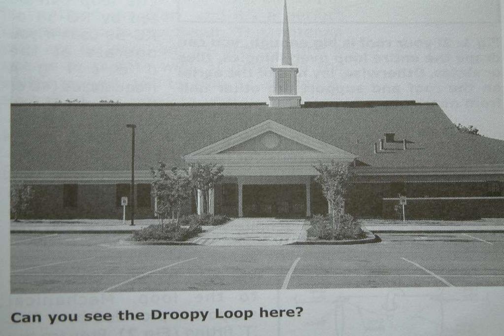
68 Antennas Dipole: Old faithful: inexpensive, easy to erect. 10 Feet high will clear foot traffic 20 Feet high will clear vehicular traffic Let center droop a couple of feet, 1-2 db increase in vertical signal strength (not for LOW dipoles) Low Traffic cone support (cut notches in the top)
69 Antenna Height Not over 1/8 wavelength 1/20th wavelength provides better coverage and lower noise 18 inches will work Raise antenna from 18 inches to 6 ft., Signal increases 10 db
70 Antenna Height Reduce height from 30 ft to 8 feet Noise level reduced from S7 to S3 Reduced signal strength May be more effective because of improved signal/noise ratio
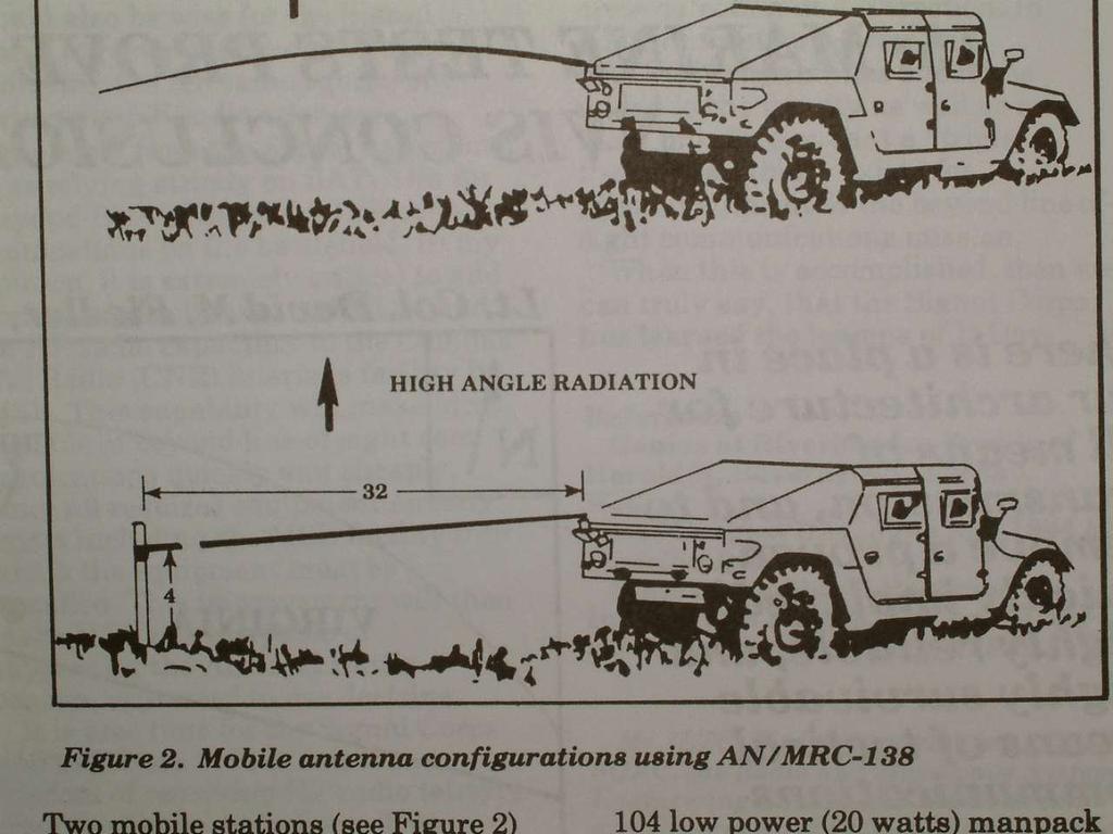
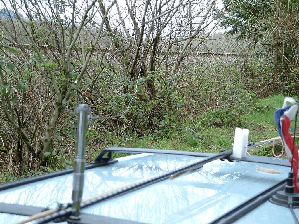
71 Antennas 2 mobile dipole antennas mounted base/base one driven, other ground. Match length Brackets $ & 40 meter. 1-2 S units lower than full- sized wire dipole at same height. Full-wave horizontal loop
72
73 Antenna Height: Variables.2 wavelength above ground gives maximum signal strength If height is reduced, so is noise pickup Most noise from distance arrives at a low angle Low height reduces low angle transmit and receive signal strength Buried antenna will work (Desert Storm)
74 NVIS Ignore traditional advice Get it LOW Minimize DX Maximize ability to reliably communicate radius up to 300 miles Reduce or eliminate groundwave and lowangle radiation
75
76
77 Frequencies Available to Amateur 160 Meter MHz 80 Meter MHz (Voice ) 40 Meter MHz (Voice ) 60 Meter 5 MHz (5 narrow channels have been approved effective 1 July 2003)
78 Propagation Considerations D layer losses Ionospheric scattering for vertical propagation Importance of critical frequency
79 Personal Experience 80 meter horiz loop Using on 75 Meter at & with tuner. Work regional nets Net controls in:» Seattle 200 miles» Hermiston 180 miles» Coeur d alene, ID 380 miles» Kelowna, B.C. 480 miles

80
81
82
83
84
85
86
87
88
89
90
91 Questions are welcome Contact Tom at Contact Ed at
92 Thank you! de Tom & Ed
93 That s All Folks
Clackamas Amateur Radio Emergency Services (CARES)
") Presented by: Clackamas Amateur Radio Emergency Services (CARES) 4/25/2015 1 NVIS Near Vertical Incident Skywave 4/25/2015 2 Introduction In this class the basic techniques in the theory, use, and making
Presented by: Clackamas Amateur Radio Emergency Services (CARES) 4/25/2015 1 NVIS Near Vertical Incident Skywave 4/25/2015 2 Introduction In this class the basic techniques in the theory, use, and making
Emergency Antennas VHF / UHF - FM. HF Voice, CW, or Digital
 1 Emergency Antennas VHF / UHF - FM HF Voice, CW, or Digital 2 Antennas for VHF Quarter Wave Vertical Half Wave Vertical Vertical Dipole J-Pole 3 Design Parameters Primarily line of sight Mounted on trunk
4/29/2012. General Class Element 3 Course Presentation. Ant Antennas as. Subelement G9. 4 Exam Questions, 4 Groups
 General Class Element 3 Course Presentation ti ELEMENT 3 SUB ELEMENTS General Licensing Class Subelement G9 Antennas and Feedlines 4 Exam Questions, 4 Groups G1 Commission s Rules G2 Operating Procedures
NVIS Near Vertical Incident Skywave 5/25/2015 1
 NVIS Near Vertical Incident Skywave 5/25/2015 1 The Problem 8/15/06 2 Introduction to NVIS What Is NVIS? What are the advantages of NVIS? How to deploy NVIS. 8/15/06 3 What Is NVIS? NVIS, or Near Vertical
Chapter 6 Antenna Basics. Dipoles, Ground-planes, and Wires Directional Antennas Feed Lines
 Chapter 6 Antenna Basics Dipoles, Ground-planes, and Wires Directional Antennas Feed Lines Some General Rules Bigger is better. (Most of the time) Higher is better. (Most of the time) Lower SWR is better.
Newspaper cartoon from the early 60 s
 Newspaper cartoon from the early 60 s NVIS for Emergency Communications Ross Mazzola Monroe County (NY) ARES Why NVIS? Damage to Infrastructure Inoperative Towers & Repeater Sites Loss of Backup Power
NVIS. Near Vertical Incident Skywave. Norm Fusaro, W3IZ 05/19/2007 1
 NVIS Near Vertical Incident Skywave Norm Fusaro, W3IZ 05/19/2007 1 Introduction What Is NVIS? What are the advantages of NVIS? How to deploy NVIS. 05/19/2007 2 What Is NVIS? NVIS, or Near Vertical Incidence
ANTENNA BASICS FOR BEGINNERS
 ANTENNA BASICS FOR BEGINNERS PART 2 -DIPOLES DIPOLES -General MULTIBAND DIPOLES RF CHOKES 1 DIPOLES Several different variations of the dipole are also used, such as the folded dipole, short dipole, cage
Basic Wire Antennas. Part II: Loops and Verticals
 Basic Wire Antennas Part II: Loops and Verticals A loop antenna is composed of a single loop of wire, greater than a half wavelength long. The loop does not have to be any particular shape. RF power can
NVIS. Norm Fusaro, W3IZ 7/25/2007 2
 7/25/2007 1 NVIS Near Vertical Incident Skywave Norm Fusaro, W3IZ 7/25/2007 2 Introduction What Is NVIS? Advantages of NVIS? How to deploy NVIS. 7/25/2007 3 What Is NVIS? Near Vertical Incidence Skywave:
Amateur Radio License. Propagation and Antennas
 Amateur Radio License Propagation and Antennas Todays Topics Propagation Antennas Propagation Modes Ground wave Low HF and below, ground acts as waveguide Line-of-Sight (LOS) VHF and above, radio waves
The Fabulous Dipole. Ham Radio s Most Versatile Antenna
 The Fabulous Dipole Ham Radio s Most Versatile Antenna 1 What is a Dipole? Gets its name from its two halves One leg on each side of center Each leg is the same length It s a balanced antenna The voltages
Beams and Directional Antennas
 Beams and Directional Antennas The Horizontal Dipole Our discussion in this chapter is about the more conventional horizontal dipole and the simplified theory behind dipole based designs. For clarity,
Antennas and Propagation Chapters T4, G7, G8 Antenna Fundamentals, More Antenna Types, Feed lines and Measurements, Propagation
 Antennas and Propagation Chapters T4, G7, G8 Antenna Fundamentals, More Antenna Types, Feed lines and Measurements, Propagation =============================================================== Antenna Fundamentals
Antennas! November 2018
 1 Antennas! November 2018 Agenda 6PM Show and Tell plus Demos in the Park 7PM Welcome: new members and visitors Announcements Antenna Overview Alpha Loop Antenna N6IET Vertical Colinear WB6MMQ Whip Dipole
FCC Technician License Course
 FCC Technician License Course 2014-2018 FCC Element 2 Technician Class Question Pool Presented by: Tamiami Amateur Radio Club (TARC) WELCOME To the third of 4, 3-hour classes presented by TARC to prepare
Chapter 5.0 Antennas Section 5.1 Theory & Principles
 Chapter 5.0 Antennas Section 5.1 Theory & Principles G3C11 (B) p.135 Which of the following antenna types will be most effective for skip communications on 40-meters during the day? A. A vertical antenna
General License Class Chapter 6 - Antennas. Bob KA9BHD Eric K9VIC
 General License Class Chapter 6 - Antennas Bob KA9BHD Eric K9VIC Learning Objectives Teach you enough to get all the antenna questions right during the VE Session Learn a few things from you about antennas
Technician Licensing Class T9
 Technician Licensing Class T9 Amateur Radio Course Monroe EMS Building Monroe, Utah January 11/18, 2014 January 22, 2014 Testing Session Valid dates: July 1, 2010 June 30, 2014 Amateur Radio Technician
VHF/UHF Beyond FM Bob Witte KØNR Page 1
 VHF/UHF Beyond FM Technical Coordinator Colorado Section Page 1 Objective The objective of this presentation is to provide an introduction to operating on VHF/UHF, going beyond the usual FM / Repeater
Multiband Vertical Antenna Project 2004 by Harold Melton, KV5R
 2004 by Harold Melton, KV5R Page 1 of 5 Printed 1/14/2004 05:02:00 PM Multiband Vertical Antenna Project 2004 by Harold Melton, KV5R Purpose If you could only have two antennas, what would they be? It
Improved Ionospheric Propagation With Polarization Diversity, Using A Dual Feedpoint Cubical Quad Loop
 Improved Ionospheric Propagation With Polarization Diversity, Using A Dual Feedpoint Cubical Quad Loop by George Pritchard - AB2KC ab2kc@optonline.net Introduction This Quad antenna project covers a practical
CHAPTER 8 ANTENNAS 1
 CHAPTER 8 ANTENNAS 1 2 Antennas A good antenna works A bad antenna is a waste of time & money Antenna systems can be very inexpensive and simple They can also be very expensive 3 Antenna Considerations
Least understood topics by most HAMs RF Safety Ground Antennas Matching & Feed Lines
 Least understood topics by most HAMs RF Safety Ground Antennas Matching & Feed Lines Remember this question from the General License Exam? G0A03 (D) How can you determine that your station complies with
One I had narrowed the options down, I installed some wire and started testing.
 Loft & Attic antennas for restricted spaces - M. Ehrenfried G8JNJ I ve recently been looking at designs for an efficient antenna that would fit in a loft. I hoped to find something that would work on with
The EMCOMM Easytenna
 The EMCOMM Easytenna This document will detail how to build an easy to install multiband dipole type antenna for emergency communications using the NVIS propagation mode. History The NVIS mode is one in
Technician License Course Chapter 4
 Technician License Course Chapter 4 Propagation, Basic Antennas, Feed lines & SWR K0NK 26 Jan 18 The Antenna System Antenna: Facilitates the sending of your signal to some distant station. Feed line: Connects
Newcomers And Elmers Net: Wire Antennas Robert AK3Q
 Newcomers And Elmers Net: Wire Antennas 02-07-16 Robert AK3Q Wire antennas represent one of the greatest values in the radio hobby world. For less than the cost of a good meal out on the town you can buy
The New and Improved Carolina Windom Antenna and ½ Wave End Fed 20 Meter Vertical and Sloping Wire Antennas. EZNEC analysis by Pete Rimmel, N8PR
 The New and Improved Carolina Windom Antenna and ½ Wave End Fed 20 Meter Vertical and Sloping Wire Antennas EZNEC analysis by Pete Rimmel, N8PR Keeps RF off the Coax below this point / (part of)/ That
Compact Multi-Band Rotatable Dipole Antenna Array
 Compact Multi-Band Rotatable Dipole Antenna Array Dr. John A. Allocca, WB2LUA, www.wb2lua.com, 4/9/12 Introduction Having limited space led to the design of this multi-band antenna array, which has a foot
4/25/2012. Supplement T9. 2 Exam Questions, 2 Groups. Amateur Radio Technician Class T9A: T9A: T9A: T9A:
 Amateur Radio Technician Class Element 2 Course Presentation ti ELEMENT 2 SUB-ELEMENTS Technician Licensing Class Supplement T9 Antennas, Feedlines 2 Exam Questions, 2 Groups T1 - FCC Rules, descriptions
Table of Contents. MFJ-1778 G5RV Multiband Antenna
 Table of Contents MFJ-1778 G5RV Multiband Antenna Introduction... 1 Theory Of Operation... 1 80 meter band:... 1 40 meter band:... 1 30 meter band:... 2 20 meter band:... 2 17 meter band:... 2 15 meter
ANTENNAS Wires, Verticals and Arrays
 ANTENNAS Wires, Verticals and Arrays Presented by Pete Rimmel N8PR 2 1 Tonight we are going to talk about antennas. Anything that will conduct electricity can be made to radiate RF can be called an antenna.
Last year I described several Low Band RX antennas that would enable you to hear DX stations on 160, 80 and 40M. This will show you how to build
 Last year I described several Low Band RX antennas that would enable you to hear DX stations on 160, 80 and 40M. This will show you how to build transmit antennas that will help you break the pileups!
Maximum Usable Frequency
 Maximum Usable Frequency 15 Frequency (MHz) 10 5 0 Maximum Usable Frequency Usable Frequency Window Lowest Usable Frequency Solar Flare 6 12 18 24 Time (Hours) Radio Blackout Usable Frequency Window Ken
A Tri Band Antenna for 2 meters, 220 MHz, and 70cm Antenna Without Radials. By: Edison Fong (WB6IQN)
") A Tri Band Antenna for 2 meters, 220 MHz, and 70cm Antenna Without Radials By: Edison Fong (WB6IQN) Twenty years ago a single band handie talkie would have been adequate for emergency use since almost
A Tri Band Antenna for 2 meters, 220 MHz, and 70cm Antenna Without Radials By: Edison Fong (WB6IQN) Twenty years ago a single band handie talkie would have been adequate for emergency use since almost
Antennas Demystified Antennas in Emergency Communications. Scott Honaker N7SS
 Antennas Demystified Antennas in Emergency Communications Scott Honaker N7SS Importance of Antennas Antennas are more important than the radio A $5000 TV with rabbit ears will have a lousy picture Antennas
Alpha Delta Communications, Inc. Model DX-OCF Off-Center-Fed 7 Band Antenna
 Alpha Delta Communications, Inc. Model DX-OCF Off-Center-Fed 7 Band Antenna 75/80, 40, 20, 17, 12, 10, and 6 meters (50.0-51.0 MHz) NO TUNER REQUIRED! Installation Instructions One leg is 45 ft., the other
User Guide for the Alpha Antenna 6 40 or meter OCF Dipole
 User Guide for the Alpha Antenna 6 40 or 10 80 meter OCF Dipole Manufactured by: Alpha Antenna 1.888.482.3249 Website: http://alphaantenna.com User Guide Version 3.0 March 23, 2018 Page 1 Table of Contents
VHF and UHF Antennas for QRP Portable Operation. Prepared for the QRP forum at Pacificon2011 by KK6MC James Duffey October 15, 2011
 VHF and UHF Antennas for QRP Portable Operation Prepared for the QRP forum at Pacificon2011 by KK6MC James Duffey October 15, 2011 Overview Get on the air from portable locations with simple and effective
Technician Licensing Class. Lesson 4. presented by the Arlington Radio Public Service Club Arlington County, Virginia
 Technician Licensing Class Lesson 4 presented by the Arlington Radio Public Service Club Arlington County, Virginia 1 Quiz Sub elements T6 & T7 2 Good Engineering Practice Sub element T8 3 A Basic Station
Chapter 7 HF Propagation. Ionosphere Solar Effects Scatter and NVIS
 Chapter 7 HF Propagation Ionosphere Solar Effects Scatter and NVIS Ionosphere and Layers Radio Waves Bent by the Ionosphere Daily variation of Ionosphere Layers Ionospheric Reflection Conduction by electrons
High Frequency Propagation (and a little about NVIS)
") High Frequency Propagation (and a little about NVIS) Tom McDermott, N5EG August 18, 2010 September 2, 2010 Updated: February 7, 2013 The problem Radio waves, like light waves, travel in ~straight lines.
High Frequency Propagation (and a little about NVIS) Tom McDermott, N5EG August 18, 2010 September 2, 2010 Updated: February 7, 2013 The problem Radio waves, like light waves, travel in ~straight lines.
Antenna Design for FM-02
 Antenna Design for FM-02 I recently received my FM-02 FM transmitter which I purchased from WLC. I researched the forum on what antennas where being used by the DIY community and found a nice write-up
Technician Licensing Class. Antennas
 Technician Licensing Class Antennas Antennas A simple dipole mounted so the conductor is parallel to the Earth's surface is a horizontally polarized antenna. T9A3 Polarization is referenced to the Earth
4/18/2012. Supplement T3. 3 Exam Questions, 3 Groups. Amateur Radio Technician Class
 Amateur Radio Technician Class Element 2 Course Presentation ti ELEMENT 2 SUB-ELEMENTS Technician Licensing Class Supplement T3 Radio Wave Characteristics 3 Exam Questions, 3 Groups T1 - FCC Rules, descriptions
N5PUV s 4 Band Fan Dipole Experiment. Using the New SRI (Stanford Research Institute) Method
 Method") N5PUV s 4 Band Fan Dipole Experiment Using the New SRI (Stanford Research Institute) Method Goals of Experiment Develop a Multi-band Antenna that does NOT require a tuner Build using the new, easier tuning
N5PUV s 4 Band Fan Dipole Experiment Using the New SRI (Stanford Research Institute) Method Goals of Experiment Develop a Multi-band Antenna that does NOT require a tuner Build using the new, easier tuning
General Class License Theory III. Dick Grote K6PBF
 General Class License Theory III Dick Grote K6PBF K6pbfdick@gmail.com 1 Introduction In this session we will learn about: Feed Lines Antennas Safety As in the other theory classes, we will try to present
DO NOT COPY. Basic HF Antennas. Bill Shanney, W6QR
 Basic HF Antennas Bill Shanney, W6QR When I was first licensed in 1961 I didn t know much about antennas. I put up the longest wire that fit on my parent s lot at the lofty height of 25 and fed it with
COAXIAL TRANSMISSION LINE COMMON-MODE CURRENT
 COAXIAL TRANSMISSION LINE COMMON-MODE CURRENT Introduction Coaxial transmission lines are popular for their wide frequency bandwidth and high resistance to electromagnetic interference (EMI). Coax cables
TBARC Programs Antenna Modeling with 4NEC2. By Randy Rogers AD7ZU 2010
 TBARC Programs Antenna Modeling with 4NEC2 By Randy Rogers AD7ZU 2010 Getting Started 4NEC2 is a completely free windows based tool suite to aid in the design and optimization of antenna systems 4NEC2
The first thing to realize is that there are two types of baluns: Current Baluns and Voltage Baluns.
 Choosing the Correct Balun By Tom, W8JI General Info on Baluns Balun is an acronym for BALanced to UNbalanced, which describes certain circuit behavior in a transmission line, source or load. Most communications
G7FEK LIMITED SPACE ANTENNA
 80, 40, 30, 17, 15, 12 m see tet for 20 & 10m operation For 20m operation add red wire 16.5ft ( 5.1m) 24 ft (7.4m) Copyright 2009 G7FEK During the 1980s Mike, G7FEK, described a limited space antenna suitable
High Performance 40 Meters Vertical Without Radials
 High Performance 40 Meters Vertical Without Radials This shortened easy-to-build vertical, with no-radials, is made from surplus military camouflage poles. It has gain and wave angle comparable to a full-sized
Near Vertical Incidence Skywave (NVIS) Antenna
 Antenna") Near Vertical Incidence Skywave (NVIS) Antenna DXE-NVIS-8040 DXE-NVIS-8040S DXE-NVIS-INS Revision 0 DX Engineering 2018 1200 Southeast Ave. - Tallmadge, OH 44278 USA Phone: (800) 777-0703 Tech Support
Near Vertical Incidence Skywave (NVIS) Antenna DXE-NVIS-8040 DXE-NVIS-8040S DXE-NVIS-INS Revision 0 DX Engineering 2018 1200 Southeast Ave. - Tallmadge, OH 44278 USA Phone: (800) 777-0703 Tech Support
A Practical NVIS Antenna for Emergency or Temporary Communications
 A Practical NVIS Antenna for Emergency or Temporary Communications Rev. 0 Optimum for 40 and 80 Meters DX Engineering 2008 P.O. Box 1491 Akron, OH 44309-1491 Phone: (800) 777-0703 Tech Support and International:
Install as much wire/tubing as possible Electrically short antennas Minimize matching losses Good ground for verticals Maximizes antenna efficiency
 Jim Wolf KR9U Install as much wire/tubing as possible Electrically short antennas Minimize matching losses Good ground for verticals Maximizes antenna efficiency Far-away ground conditions determine low
ANTENNA THEORY WAVE PROPAGATION HF ANTENNAS
 ANTENNA THEORY WAVE PROPAGATION & HF ANTENNAS FREQUENCY SPECTRUM INFORMATION Frequency range American designator below 300 Hz..ELF (extremely Low Frequency) 300-3000 Hz..ILF (Intermediate Low Frequency)
# -antenna (hash) 4 direction switchable array
 4 direction switchable array") # -antenna (hash) 4 direction switchable array Feasibility study Paper on CCF & OHDXF cruise 4.1.2012 Pekka Ketonen 4.2.2012 OH1TV 1 4 direction, instant switching 4.2.2012 OH1TV 2 Features Instant direction
# -antenna (hash) 4 direction switchable array Feasibility study Paper on CCF & OHDXF cruise 4.1.2012 Pekka Ketonen 4.2.2012 OH1TV 1 4 direction, instant switching 4.2.2012 OH1TV 2 Features Instant direction
Antenna Systems for the Recently Licensed Ham --3 Talks-- BVARC Meeting May 10 th, 2012
 Antenna Systems for the Recently Licensed Ham --3 Talks-- BVARC Meeting May 10 th, 2012 Understanding the Cardinal Rules of the Ham Radio Antenna System Rick Hiller -- W5RH Utilizing Your New Found Practical
ANOTHER MULTIBAND WIRE ANTENNA
 ANOTHER MULTIBAND WIRE ANTENNA Above The multiband long wire with balun (cover is off) by Ron VK3AFW. I wanted to build a simple wire antenna dedicated to 30 m and 17m for operation during the 2015 ILLW
9.5 Half-Sloper Antennas MHz Antenna Systems Using Towers
 TABLE OF CONTENTS 9.1 Horizontal Antennas 9.1.1 Dipole Antennas 9.1.2 Folded Dipoles 9.1.3 Inverted-V Dipole 9.1.4 End-Fed Zepp 9.1.5 Sloping Dipoles 9.1.6 Broadband Dipoles 9.2 Vertical Antennas 9.2.1
1) Transmission Line Transformer a. First appeared on the scene in 1944 in a paper by George Guanella as a transmission line transformer, the 1:1
 Transmission Line Transformer a. First appeared on the scene in 1944 in a paper by George Guanella as a transmission line transformer, the 1:1") 1) Transmission Line Transformer a. First appeared on the scene in 1944 in a paper by George Guanella as a transmission line transformer, the 1:1 Guanella Balun is the basic building Balun building block.
1) Transmission Line Transformer a. First appeared on the scene in 1944 in a paper by George Guanella as a transmission line transformer, the 1:1 Guanella Balun is the basic building Balun building block.
4 Antennas as an essential part of any radio station
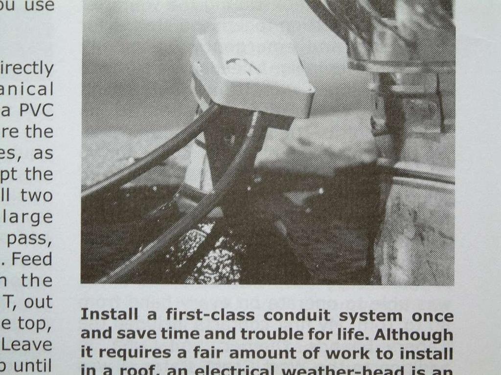
 4 Antennas as an essential part of any radio station 4.1 Choosing an antenna Communicators quickly learn two antenna truths: Any antenna is better than no antenna. Time, effort and money invested in the
An Attic Coaxial-Cable Trap Dipole for 10, 15, 20, 30, 40, and 80 Meters
 1 van 11 4-6-2010 14:23 An Attic Coaxial-Cable Trap Dipole for 10, 15, 20, 30, 40, and 80 Meters John DeGood, NU3E nu3e@arrl.net Abstract A coaxial-cable trap dipole antenna installed in the attic provides
SOME USES FOR RF1,RF5 and VA1 ANALYSTS. SWR Measurement
 SOME USES FOR RF1,RF5 and VA1 ANALYSTS THE HANDIEST INSTRUMENTS IN DECADES! When you put up an antenna in the the old days, it could be a real struggle. The only way to tell if it was tuned to the right
QRP Presentation at HRU John Meade W2XS. Contact Info:
 QRP Presentation at HRU John Meade W2XS Contact Info: jm416@optonline.net John.meade@ncc.edu Topics QRP Presentation at HRU John Meade W2XS Philosophy of QRP Equipment Antennas My QRP Rig History in Pictures
Cushcraft. Amateur Radio Antennas LFA-6M5EL. 6 Meter 5 Element Loop Feed Antenna INSTRUCTION MANUAL
 Cushcraft Amateur Radio Antennas LFA-6M5EL 6 Meter 5 Element Loop Feed Antenna INSTRUCTION MANUAL CAUTION: Read All Instructions Before Operating Equipment VERSION 1A Cushcraft Amateur Radio Antennas 308
Yagi Antenna Tutorial. Copyright K7JLT 1
 Yagi Antenna Tutorial Copyright K7JLT Yagi: The Man & Developments In the 920 s two Japanese electrical engineers, Hidetsugu Yagi and Shintaro Uda at Tohoku University in Sendai Japan, investigated ways
Hardware Store 40m Magnetic Loop Antenna for Regional and EMCOM Use. Richard Bono NO5V. QST Antenna Design Competition 80 through 10 meter entry
 Hardware Store 40m Magnetic Loop Antenna for Regional and EMCOM Use Richard Bono NO5V QST Antenna Design Competition 80 through 10 meter entry Overview: This describes a field deployable magnetic loop
Small Magnetic Loops: A Beginner s Guide WOW! This is a very different antenna!
 Small Magnetic Loops: A Beginner s Guide WOW! This is a very different antenna! Dave Wickert, AE7TD Lake Washington Ham Club November 2018 Meeting 10-Nov-2018 Dayton Hamvention 2017 History Full Size Loops
Exploring the HF Bands
 Exploring the HF Bands By Frank Tomkins, W8EZT Cuyahoga Falls Amateur Radio Club What You Need to Get There, What To Do Once You Are There, and Some Useful Operating Tips 1 The HF Bands As Technicians
Antennas and Stuff. John Kernkamp WB4YJT
 Antennas and Stuff John Kernkamp WB4YJT John Kraus W8JK June 28, 1910 - July 18, 2004 Invented the helical antenna, the corner reflector, and the W8JK End-Fire array. In 1950 designed and built the Big
A Triangle for the Short Vertical
 1 von 11 03.03.2015 12:37 A Triangle for the Short Vertical Operator L. B. Cebik, W4RNL Last month, I described a triangle array of three full-size vertical dipoles for 40 meters (with 30 meters as a bonus).
Adjust Antenna Tuners Antenna Measurements Capacitor Measurement Measure Feed Point Impedance Measure Ground Loss Inductor Measurement
 The Micro908 antenna analyzer is an extremely useful instrument to have around the ham shack or homebrewer s workbench. This section describes the basic uses, as well as some advanced techniques for which
Array Solutions. Model AS-AYL-4 4-way K9AY Loop System
 Array Solutions Model AS-AYL-4 4-way K9AY Loop System This is the popular K9AY Loop receiving antenna, as described in the September 1997 issue of QST, The K9AY Terminated Loop-A Compact, Directional Receiving
M2 Antenna Systems, Inc. Model No: 2M HO LOOP
 M2 Antenna Systems, Inc. Model No: 2M HO LOOP SPECIFICATIONS: Model... 2M HO LOOP Frequency Range... 144 To 144.5 MHz Gain, Typical @ 10 ft.... 4 dbd @ 10 deg. Gain, 2 STK @ 82 & 132... 8 dbd @ 9 deg.
RECOMMENDATION ITU-R F Characteristics of HF fixed radiocommunication systems
 Rec. ITU-R F.1761 1 RECOMMENDATION ITU-R F.1761 Characteristics of HF fixed radiocommunication systems (Question ITU-R 158/9) (2006) Scope This Recommendation specifies the typical RF characteristics of
Discover the Magic Of. HF Radio
 Discover the Magic Of HF Radio Welcome to Worldwide Communications This presentation is designed to introduce the new or recently upgraded ham to HF radio. Welcome to Worldwide Communications The information
Build a 12/17 Meter Trap Dipole Phil Salas AD5X
 Build a 12/17 Meter Trap Dipole Phil Salas AD5X Introduction Why a 12/17 meter rotatable dipole? Well, many folks have verticals for the lower bands, and multi-band dipoles or beams for 20-, 15-, and 10
Portable Vertical Antenna for 75m & 40m
 Portable Vertical Antenna for 75m & 40m BOXBORO August 2012 Jacques VE2AZX Web: ve2azx.net 1 Objectives 1- Portable Antenna for 75m et 40m 2- Low radiation angle for DX 3- Efficient 4- Easy to install.
Installation Instructions Hustler 6-BTV Trap Vertical
 Installation Instructions Hustler 6-BTV Trap Vertical ASSEMBLY 1. Check the package contents against the parts list on page 2. 2. WARNING. Installation of this product near power lines is dangerous. For
Intermediate Course (5) Antennas and Feeders
 Antennas and Feeders") Intermediate Course (5) Antennas and Feeders 1 System Transmitter 50 Ohms Output Standing Wave Ratio Meter Antenna Matching Unit Feeder Antenna Receiver 2 Feeders Feeder types: Coaxial, Twin Conductors
Intermediate Course (5) Antennas and Feeders 1 System Transmitter 50 Ohms Output Standing Wave Ratio Meter Antenna Matching Unit Feeder Antenna Receiver 2 Feeders Feeder types: Coaxial, Twin Conductors
Emergency Antennas. Presented by Ham Hilliard W4GMM
 Emergency Antennas Presented by Ham Hilliard W4GMM Dipole antenna Vertical antenna Random wire antenna Dipole antenna The half wave dipole antenna consists of a conductive wire or rod that is half the
INSTRUCTION MANUAL HF AUTOMATIC TUNING ANTENNA AH-740. * The stand in the photo is not supplied with the tuning antenna.
 INSTRUCTION MANUAL HF AUTOMATIC TUNING ANTENNA AH-740 * The stand in the photo is not supplied with the tuning antenna. FOREWORD Thank you for purchasing the AH-740 hf au to m at i c tuning antenna. The
TENNADYNE TD-160HP800
 TENNADYNE Aluminum with a PhD ASSEMBLY INSTRUCTIONS TD-160HP800 SPECIFICATIONS: Impedance: 50 Ohm nominal Bandwidth :1.8-30 MHz Length : 160 ft. Power : 8 KW Impulse 2400 W PEP SSB 800 W AM/FM/RTTY Connector
Lighthouse Program: Neighbors Helping Neighbors
 Lighthouse Program: Neighbors Helping Neighbors What is the Lighthouse Program? A citizen-driven initiative to prepare for potential emergency or disaster conditions that include a reduction or loss of
ANTENNA MATRIX. Antenna Matrix. Purpose. Using the Antenna Selection Proforma
 Purpose The purpose of this Antenna Matrix is to assist you in deciding which antenna from Codan s range best suits your requirements for high frequency (HF) communication over the 2 30 MHz range. The
Page 1The VersaTee Vertical 60m, 80m Modular Antenna System Tutorial Manual
 Page 1The VersaTee Vertical 60m, 80m Modular Antenna System Tutorial Manual by: Lou Rummel, KE4UYP Page 1 In the world of low band antennas this antenna design is unique in many different ways. 1. It is
A 2 ELEMENT 30 METER PARASITIC VERTICAL ARRAY PROJECT
 A 2 ELEMENT 30 METER PARASITIC VERTICAL ARRAY PROJECT Having killed off the 5B-DXCC purely using LOTW, it was time for the addition of a new band. 30 meters was selected based on lack of sunspots and a
4/29/2012. General Class Element 3 Course Presentation. Radio Wave Propagation. Radio Wave Propagation. Radio Wave Propagation.
 General Class Element 3 Course Presentation ti ELEMENT 3 SUB ELEMENTS General Licensing Class Subelement G3 3 Exam Questions, 3 Groups G1 Commission s Rules G2 Operating Procedures G3 G4 Amateur Radio
Plotting all this data got old using a chart to look up VSWR each time. Here is a formula I found rooting around the web. Let Excel do the work
 My compliments to John, K5GD for heading up the antenna building sessions, and thanks to Ron, N5QV for providing the antenna comparison data. I wanted to share my experience with this project. First of
AD5X. Low Cost HF Antennas & Accessories. Phil Salas - AD5X Phil Salas AD5X. Richardson, Texas
 Low Cost HF Antennas & Accessories Phil Salas - AD5X ad5x@arrl.net PVC Tubing PVC pipe: Considers the inside diameter (ID) of the pipe. For PVC pipe (schedule 40): 1/2" PVC pipe has an ID of 0.6" and an
Working Bouvet with the Innovative and Cheap N6MW, Bill Wortman
 Working Bouvet with the Innovative and Cheap N6MW, Bill Wortman Trying to work the upcoming early 2018 Bouvet Dxpedition for an all time new one (ATNO as we say) is a serious challenge for those with only
The A-B-C's of Radio Waves and Antennas
 The A-B-C's of Radio Waves and Antennas By Greg S. Carpenter GregsBasicElectronics.com What is the most important thing in common with both the transmitter and receiver? It's the antenna and without a
The Three L-Antennas Wide Equal - Tall
 Wide Equal - Tall Dick Reid, KK4OBI A space saving antenna in the form of an upright L has been around the amateur radio world for a long time. References are found back to a QST article in the 60 s (Reference
Antenna Fundamentals
 HTEL 104 Antenna Fundamentals The antenna is the essential link between free space and the transmitter or receiver. As such, it plays an essential part in determining the characteristics of the complete
Nick Garner N3WG and George Zafiropoulos KJ6VU
 Nick Garner N3WG and George Zafiropoulos KJ6VU Introduction Over the last few years, there has been a significant increase in the number of radio amateurs interested in portable operating. This is due
ANTENNA DESIGN FOR FREE USING MMANA-GAL SOFTWARE
 ANTENNA DESIGN FOR FREE USING MMANA-GAL SOFTWARE 1. AVAILABLE ANTENNA DESIGN SOFTWARE EZNEC and 4nec2 are based upon the Numerical Electromagnetics Code, or NEC, which is a popular antenna modelling system
AD5X. The 43-Foot Vertical. Phil Salas - AD5X Phil Salas AD5X. Richardson, Texas
 The 43-Foot Vertical Phil Salas - AD5X ad5x@arrl.net Outline Why a vertical? Ground Losses and Antenna Efficiency Why a 43-foot vertical? SWR-related coax and unun losses Matching Networks for 160- and