Compact Multi-Band Rotatable Dipole Antenna Array
|
|
|
- Claire Allison
- 6 years ago
- Views:
Transcription
1 Compact Multi-Band Rotatable Dipole Antenna Array Dr. John A. Allocca, WB2LUA, 4/9/12 Introduction Having limited space led to the design of this multi-band antenna array, which has a foot print of approximately 15 feet. Because dipoles are directional, as seen in the Dipole Radiation 3D Pattern diagram, an antenna rotator is required for maximum antenna gain in a specific direction. Two 1/4 wave ham sticks in a dipole configuration produce a 1/2 wave dipole antenna. The four bands planned are 80 meters, 40 meters, 20 meters, and 10 meters. However, almost any combination of ham sticks can be used. A 2m/70cm vertical antenna may be placed on top of the three foot aluminum mounting pole along with an additional coaxial cable. Dipole antennas were invented by German physicist Heinrich Hertz around 1886 in his pioneering experiments with radio waves. The antenna array may be configured in different ways. The array can be used without a rotator if one direction is primarily used. The antenna array may also be configured without the rotator and without the 2m/70cm antenna for use in an attic horizontally. A test was setup in Northport, NY with the antenna array facing North and South. Signal reports of 5 x 7 were received from Rhode Island and New Jersey (East and West). Signal reports of 5 x 9 were received from Maryland (South). Construction Four dipole mounts are mounted on a 1-1/4 aluminum pole as shown in the photo. The MFJ dipole mounts will not fit a pole wider than 1-1/4. Only two pairs of ham sticks were mounted in this photo because the others were on backorder at the time of the photo. The final configuration was used horizontally in an attic. The four position remote antenna switch is mounted on the same pole in the center. Four 18 inch RG8X cables are connected from each dipole to the antenna switch. Nonconductive 1/8 nylon cords are tied from the end of the black ham stick portion to the top of the mast to prevent the ham sticks from sagging. The dipole connections are as follows: ANT 1 is connected to the 10 meter dipole ANT 2 is connected to the 20 meter dipole ANT 3 is connected to the 40 meter dipole ANT 4 is connected to the 80 meter dipole. The feed line is connected to the CONTROL CONSOLE connector. There is no control wire required for this antenna switch. Control signals are passed through the coaxial feed line. A 3 wire cable is connected to the antenna rotator. The pole is mounted to the antenna rotator. It is extremely important to tune the ham sticks as a pair in the dipole configuration with an antenna analyzer. The whips on each ham stick of a pair should be the same length. Do not tune the ham sticks individually. The ham stick dipole whips were tuned approximately as follows: 3.8 MHz. (40.0 ), MHz. (39.5 ), MHz. (39.5 ), and MHz. (39.0 ). 1
 NVIS propagation is a propagation pattern that uses antennas with high-angle radiation (almost 90 degrees, vertical) and low operating frequencies.")
2 The radiation pattern above is not to scale. The dipole antenna is 15 feet wide. The radiation pattern is hundreds and thousands of miles. Near Vertical Incidence Sky Wave (NVIS) NVIS propagation is a propagation pattern that uses antennas with high-angle radiation (almost 90 degrees, vertical) and low operating frequencies. The primary range is about miles. The pattern may extend beyond 300 miles depending antenna height and upon environmental conditions. Long distance propagation uses radio waves that are reflected from the ionosphere and return to earth at some distance away. Radio waves that are radiated at a very low angle, travel a long distance to reach the ionosphere at a very shallow angle and return to earth far away. When the angle of radiation increases, the radio waves reach the ionosphere at a greater angle, and return to earth closer to their point of origin. Signals that reach the ionosphere at a higher angle of incidence will not be reflected at all, but will continue out into space. The area of reflection that would have occurred is the "skip zone". Depending on operating frequencies, antennas, and propagation conditions, this skip zone can start at roughly 12 to 18 miles and extend out to several hundred miles, preventing communications. NVIS antennas are designed to minimize the ground wave (low takeoff angle) radiation and maximize the sky wave (very high takeoff angle, degrees). Essentially, the NVIS antenna radiates a wave almost straight up, then bounces from the ionosphere and returns to the Earth in a circular pattern around the transmitter. Because of the near-vertical radiation angle, there is no skip zone. Communications are continuous out to several hundred miles from the transmitter. The nearly vertical angle of radiation requires the use of lower frequencies, usually 2-10 MHz. This type of propagation is excellent when communicating over hills and mountains. These frequencies are the same frequencies that contain a lot of atmospheric noise, such as distant thunderstorms. The NVIS antenna is optimized for listening to signals from nearby areas, and minimizes the reception of signals from distant sources. 2
3 One of the most effective antennas for NVIS is a dipole that is mounted from 0.1 to 0.25 wavelengths above ground. When a dipole is brought very close two ground, the angle of radiation increases. In the range of 0.1 to 0.25 wavelengths above ground, vertical and nearly vertical radiation reaches a maximum. A dipole can be used at even lower heights, resulting in some loss of vertical gain, but often, a more substantial reduction in noise and interference from distant regions. Heights of 5 to 10 feet above ground are not unusual for NVIS operation. During a test by WOIPL, they used a 75-meter dipole at a height of 30 feet. They found the communications to be difficult. They set up a second dipole at a height of 8 feet. The background noise went from S7 to S3 and the communications with stations 25 miles and further, greatly improved. Many people find the 10 to 15 foot height to be ideal. Field tests have proven that the maximum NVIS efficiency is obtained at the 10 to 15 foot height for frequencies in the 40 meter to 75 meter range. RACES within uses 80 meters for NVIS communications within a state. Full Wavelength Antennas: /2 Wavelength Antennas: /4 Wavelength Antennas:
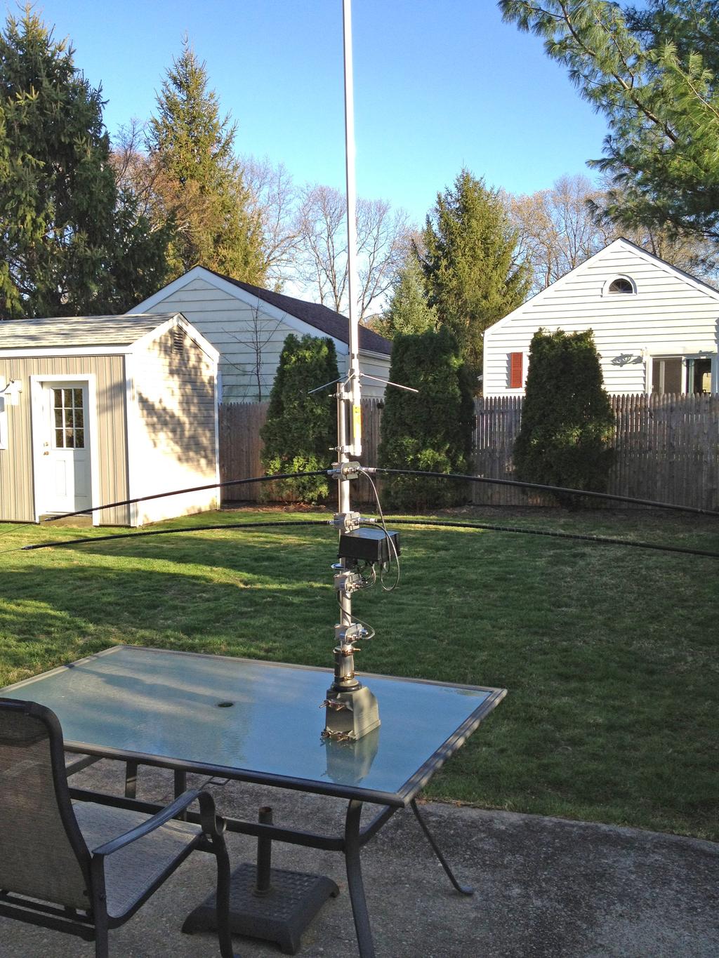
4 Photo 4
5 Parts List Four MFJ-347 3/8-24, Double T Pipe Mount, with SO-239, $19.95 x 4 = $79.80 Channel Master RC Antenna Rotator System, Model: CM-9521A, $99.99, Radio Shack Ft. Rotator Control Cable, Model: , $24.95, Radio Shack (2) 75m MFJ Ham sticks, $19.99 each x 2 = $39.98 (2) 40m MFJ Ham sticks, $14.95 each x 2 = $29.90 (2) 20m MFJ Ham sticks, $14.95 each x 2 = $29.90 (2) 10m MFJ Ham sticks, $14.95 each x 2 = $29.90 Aluminum Tubing, 1-1/4" OD, 1.084" ID,.083" Wall Thickness, 3' L, $35.80, McMaster-Carr 9056K772 UHF Male to UHF Female Right Angle adapter, $9.00 Ameritron RCS-4, remote antenna switch, $ Cable Experts CXP08XC18INCH, 18 inch RG8X cable with PL-259 connectors, $17.95 x 4 = $ Total $ Extras if needed: 20 foot Antenna Mast Antennacraft 10-Ft. 16-Gauge Mast, Radio Shack Catalog #: , $29.99 x 2 = $59.98 Cable Experts CXP08XC100, 100 feet RG8X cable with PL-259 connectors, $54.95 Mounting brackets Portable Mast and Tripod: Use 4 sections of the 1-1/4 OD, 3 feet aluminum tubing. Cut the 1-3/8 OD tubing into three 12 inch sections. Position the 12 sections over the joint of two of the 3 feet sections. Drill through the two sections with 5/16 holes and use 1/4-20 screws, washers, lock washers, and hex nuts to join the sections. Insert the end of the assembled 4 sections into the PA speaker stand. Two 6 foot 1-1/4 OD sections can also be used in place of the 4 three foot sections. Aluminum Tubing, 1-1/4" OD, 1.084" ID,.083" Wall Thickness, 3' L, $35.80, McMaster-Carr 9056K772 Aluminum Tubing, 1-3/8" OD, 1.259" ID,.058" Wall Thickness, 3' L, $29.59, McMaster-Carr 89965K415 PA speaker stand that uses 1-1/4 OD tubing available from most musical instrument stores 5
Portable Antenna Systems
 Portable Antenna Systems Dr. John A. Allocca, WB2LUA www.wb2lua.com 3/6/16 System 1 - HF / VHF / UHF Tripod VHF/UHF Antenna Dipole Mount HF Hamstick Case! 1 of! 5 Introduction This antenna configuration
Mast and Antennas for Field Day & Emergencies
 Mast and Antennas for Field Day & Emergencies John A. Allocca, WB2LUA, July 2005 This is a 27 feet 1.5 diameter portable guyed mast with a 28 feet diameter footprint. It breaks down into four 6 feet sections
Emergency Antennas VHF / UHF - FM. HF Voice, CW, or Digital
 1 Emergency Antennas VHF / UHF - FM HF Voice, CW, or Digital 2 Antennas for VHF Quarter Wave Vertical Half Wave Vertical Vertical Dipole J-Pole 3 Design Parameters Primarily line of sight Mounted on trunk
The EMCOMM Easytenna
 The EMCOMM Easytenna This document will detail how to build an easy to install multiband dipole type antenna for emergency communications using the NVIS propagation mode. History The NVIS mode is one in
AD5X. Low Cost HF Antennas & Accessories. Phil Salas - AD5X Phil Salas AD5X. Richardson, Texas
 Low Cost HF Antennas & Accessories Phil Salas - AD5X ad5x@arrl.net PVC Tubing PVC pipe: Considers the inside diameter (ID) of the pipe. For PVC pipe (schedule 40): 1/2" PVC pipe has an ID of 0.6" and an
M2 Antenna Systems, Inc. Model No: 2M HO LOOP
 M2 Antenna Systems, Inc. Model No: 2M HO LOOP SPECIFICATIONS: Model... 2M HO LOOP Frequency Range... 144 To 144.5 MHz Gain, Typical @ 10 ft.... 4 dbd @ 10 deg. Gain, 2 STK @ 82 & 132... 8 dbd @ 9 deg.
Technician Licensing Class. Antennas
 Technician Licensing Class Antennas Antennas A simple dipole mounted so the conductor is parallel to the Earth's surface is a horizontally polarized antenna. T9A3 Polarization is referenced to the Earth
The W3FF Portable Dipole
 The W3FF Portable Dipole This is the antenna I designed for my 'walking portable' station. It is a dipole constructed out of the plastic plumbing pipe CPVC. There are telescoping whips at the ends of each
Chapter 5.0 Antennas Section 5.1 Theory & Principles
 Chapter 5.0 Antennas Section 5.1 Theory & Principles G3C11 (B) p.135 Which of the following antenna types will be most effective for skip communications on 40-meters during the day? A. A vertical antenna
Chapter 7 HF Propagation. Ionosphere Solar Effects Scatter and NVIS
 Chapter 7 HF Propagation Ionosphere Solar Effects Scatter and NVIS Ionosphere and Layers Radio Waves Bent by the Ionosphere Daily variation of Ionosphere Layers Ionospheric Reflection Conduction by electrons
FCC Technician License Course
 FCC Technician License Course 2014-2018 FCC Element 2 Technician Class Question Pool Presented by: Tamiami Amateur Radio Club (TARC) WELCOME To the third of 4, 3-hour classes presented by TARC to prepare
DP-100 half wave Dipole Antenna Manual
 DP-100 half wave Dipole Antenna Manual 1. Introduction: A dipole antenna is a radio antenna that can be made of aluminum, copper, and bronze tube with a center-fed driven element. It consists of two metal
Newspaper cartoon from the early 60 s
 Newspaper cartoon from the early 60 s NVIS for Emergency Communications Ross Mazzola Monroe County (NY) ARES Why NVIS? Damage to Infrastructure Inoperative Towers & Repeater Sites Loss of Backup Power
THE W3FF HOMEBREW BUDDIPOLE
 THE W3FF HOMEBREW BUDDIPOLE A PORTABLE ANTENNA DESIGN FOR AMATEUR RADIO History of the Buddipole In January of 2000, I began experimenting with a walking portable ham station. Since then, thousands of
MFJ-2100 INSTRUCTION MANUAL. CAUTION: Read All Instructions Before Operating Equipment
 MFJ-2100 INSTRUCTION MANUAL CAUTION: Read All Instructions Before Operating Equipment 300 Industrial Park Road Starkville, MS 39759 USA Tel: 662-323-5869 Fax: 662-323-6551 COPYRIGHT C 2015 MFJ Enterprises
MFJ Manual Loop Tuner Considerations
 Pagina 1 0 items Proceed to Secure Checkout All Categories Accessories Analyzers Products Tuners Morse Code / CW Power Supplies Product Search Search! List All Products Site Menu Customer Account Order
The J-Pole Antenna. Gary Wescom
 The J-Pole Antenna Gary Wescom - 2018 Much has been written about the J-Pole antenna. A simple Google search will net days worth of reading material on the subject. That would tend to indicate this paper
Hardware Store 40m Magnetic Loop Antenna for Regional and EMCOM Use. Richard Bono NO5V. QST Antenna Design Competition 80 through 10 meter entry
 Hardware Store 40m Magnetic Loop Antenna for Regional and EMCOM Use Richard Bono NO5V QST Antenna Design Competition 80 through 10 meter entry Overview: This describes a field deployable magnetic loop
Technician Licensing Class T9
 Technician Licensing Class T9 Amateur Radio Course Monroe EMS Building Monroe, Utah January 11/18, 2014 January 22, 2014 Testing Session Valid dates: July 1, 2010 June 30, 2014 Amateur Radio Technician
Chapter 6 Antenna Basics. Dipoles, Ground-planes, and Wires Directional Antennas Feed Lines
 Chapter 6 Antenna Basics Dipoles, Ground-planes, and Wires Directional Antennas Feed Lines Some General Rules Bigger is better. (Most of the time) Higher is better. (Most of the time) Lower SWR is better.
Antennas and Propagation Chapters T4, G7, G8 Antenna Fundamentals, More Antenna Types, Feed lines and Measurements, Propagation
 Antennas and Propagation Chapters T4, G7, G8 Antenna Fundamentals, More Antenna Types, Feed lines and Measurements, Propagation =============================================================== Antenna Fundamentals
2014 MFJ ENTERPRISES, INC.
 Model MFJ-1907 INSTRUCTION MANUAL CAUTION: Read All Instructions Before Operating Equipment MFJ ENTERPRISES, INC. 300 Industrial Park Road Starkville, MS 39759 USA Tel: 662-323-5869 Fax: 662-323-6551 VERSION
CP6 6 Band Trap Vertical 80-6m
 CP6 6 Band Trap Vertical 80-6m Instruction Sheet The CP6 is a multi-band trap-vertical antenna for HF bands, covering the 80*, 40, 20, 15, 10m & 6m amateur bands. Made from heavy duty aluminum, the CP6
4/29/2012. General Class Element 3 Course Presentation. Ant Antennas as. Subelement G9. 4 Exam Questions, 4 Groups
 General Class Element 3 Course Presentation ti ELEMENT 3 SUB ELEMENTS General Licensing Class Subelement G9 Antennas and Feedlines 4 Exam Questions, 4 Groups G1 Commission s Rules G2 Operating Procedures
4/25/2012. Supplement T9. 2 Exam Questions, 2 Groups. Amateur Radio Technician Class T9A: T9A: T9A: T9A:
 Amateur Radio Technician Class Element 2 Course Presentation ti ELEMENT 2 SUB-ELEMENTS Technician Licensing Class Supplement T9 Antennas, Feedlines 2 Exam Questions, 2 Groups T1 - FCC Rules, descriptions
Technician License. Course
 Technician License Course Technician License Course Chapter 4 Lesson Plan Module - 10 Practical Antennas The Dipole Most basic antenna The Dipole Most basic antenna The Dipole Total length is ½ wavelength
User Guide. For. Alpha Antenna. Model: Multiband (Black Match)
") User Guide For Alpha Antenna Model: Multiband (Black Match) Manufactured by: Alpha Antenna 1.888.482.3249 Website: http://alphaantenna.com Available from the: AmateurRadioStore.com Website: https://amateurradiostore.com
User Guide For Alpha Antenna Model: Multiband (Black Match) Manufactured by: Alpha Antenna 1.888.482.3249 Website: http://alphaantenna.com Available from the: AmateurRadioStore.com Website: https://amateurradiostore.com
CP6A. 6 Band Trap Vertical 75-6m
 CP6A 6 Band Trap Vertical 75-6m Instruction Sheet The CP6A is a multi-band trap-vertical antenna for HF bands, covering the 75*, 40, 20, 15, 10m & 6m amateur bands. Made from heavy duty aluminum, the CP6A
NVIS Near Vertical Incident Skywave 5/25/2015 1
 NVIS Near Vertical Incident Skywave 5/25/2015 1 The Problem 8/15/06 2 Introduction to NVIS What Is NVIS? What are the advantages of NVIS? How to deploy NVIS. 8/15/06 3 What Is NVIS? NVIS, or Near Vertical
NVIS, Another Look. Tom Sanders, W6QJI Ed Bruette, N7NVP
 NVIS, Another Look Tom Sanders, W6QJI Ed Bruette, N7NVP Regional Communications N.V.I.S. Near Vertical Incidence Skywave What is NVIS? Near Vertical Incident Skywave Cloud Warmer Propagation Theory NVIS
Clackamas Amateur Radio Emergency Services (CARES)
") Presented by: Clackamas Amateur Radio Emergency Services (CARES) 4/25/2015 1 NVIS Near Vertical Incident Skywave 4/25/2015 2 Introduction In this class the basic techniques in the theory, use, and making
Presented by: Clackamas Amateur Radio Emergency Services (CARES) 4/25/2015 1 NVIS Near Vertical Incident Skywave 4/25/2015 2 Introduction In this class the basic techniques in the theory, use, and making
Nick Garner N3WG and George Zafiropoulos KJ6VU
 Nick Garner N3WG and George Zafiropoulos KJ6VU Introduction Over the last few years, there has been a significant increase in the number of radio amateurs interested in portable operating. This is due
CHAPTER 8 ANTENNAS 1
 CHAPTER 8 ANTENNAS 1 2 Antennas A good antenna works A bad antenna is a waste of time & money Antenna systems can be very inexpensive and simple They can also be very expensive 3 Antenna Considerations
Portable or Emergency VHF Antennas Paul R. Jorgenson KE7HR
 For emergency or public service events it is often necessary to have more antenna than the rubber duck on your handheld VHF radio. Nearly ANY external antenna will provide more coverage for your handheld
Chapter 3 Antennas. Section I. Antenna Selection FM 24-19
 Chapter 3 Antennas One of the most important considerations when operating a radio is the type of antenna to be used. For good communications with a radio operating in the HF range (2.000 khz to 29.999
User Instructions Multiline Otter Scoreboard Caddy Assembly
 List of parts: User Instructions Multiline Otter Scoreboard Caddy Assembly Single Caddy Double Caddy 1 1 Base assembly with attached wheels 2 4 1 1 2 4 4 8 10 20 12 Uprights (60 or 74 aluminum extrusion)
INSTRUCTION MANUAL ORDER NO. V3R MODEL V3R. Collinear Gain Vertical for MHz
 ORDER NO. V3R MODEL V3R Collinear Gain Vertical for 216-225 MHz INSTRUCTION MANUAL General Description The new Hy-Gain V3R VHF antenna is a collinear 5/8-wave omnidirectional vertical antenna for the 216-225
20m G4BUD Mobile Whip
 This particular antenna was built specifically to take on holiday to Fuerteventura in the Canary Islands, after it was originally tested from an inland site in the UK. Amongst my first contacts using the
INSTRUCTION MANUAL. Specifications Mechanical. 1 5/8 to 2 1/16 O.D. (41mm to 52mm)
") 308 Industrial Park Road Starkville, MS 39759 USA Ph: (662) 323-9538 FAX: (662) 323- General Description Model VB-25FM 2-Meter 5 Elements Beam INSTRUCTION MANUAL This antenna is a 5-element, 2-meter beam
308 Industrial Park Road Starkville, MS 39759 USA Ph: (662) 323-9538 FAX: (662) 323- General Description Model VB-25FM 2-Meter 5 Elements Beam INSTRUCTION MANUAL This antenna is a 5-element, 2-meter beam
Amateur Radio License. Propagation and Antennas
 Amateur Radio License Propagation and Antennas Todays Topics Propagation Antennas Propagation Modes Ground wave Low HF and below, ground acts as waveguide Line-of-Sight (LOS) VHF and above, radio waves
Model VB-23FM 2-Meter 3-Element Beam
 308 Industrial Park Road Starkville, MS 39759 USA Ph: (662) 323-9538 FAX: (662) Model VB-23FM 2-Meter 3-Element Beam [ INSTRUCTION MANUAL Figure 1 Overall View and Boom Detail GENERAL DESCRIPTION This
PACKING LIST MACO V-5000
 PACKING LIST MACO V-5000 PART QTY O.D. SIZE LENGTH DESCRIPTION CHECKLIST T47P 4 5/8.050 36 Aluminum Tubing _ T43P 1 7/8.050 48 Aluminum Tubing _ T18P 1 3/4.050 48 Aluminum Tubing _ T15P 1 5/8.050 48 Aluminum
The Octopus Antenna A 4-BAND 8-ELEMENT DIPOLE ARRAY CLIFF PULIS, KE0CP CONSTRUCTED BY
 The Octopus Antenna A 4-BAND 8-ELEMENT DIPOLE ARRAY CONSTRUCTED BY CLIFF PULIS, KE0CP WHAT IS IT? Multi-Band somewhat directional antenna Basic design uses 4-rigid dipoles (8 elements) arranged in a circular
NVIS. Near Vertical Incident Skywave. Norm Fusaro, W3IZ 05/19/2007 1
 NVIS Near Vertical Incident Skywave Norm Fusaro, W3IZ 05/19/2007 1 Introduction What Is NVIS? What are the advantages of NVIS? How to deploy NVIS. 05/19/2007 2 What Is NVIS? NVIS, or Near Vertical Incidence
HFp. User s Guide. Vertical. entenna. 7 MHz 30 MHz Amateur Radio Antenna Plus 6-Meters
 User s Guide HFp Vertical 7 MHz 30 MHz Amateur Radio Antenna Plus 6-Meters The Ventenna Co. LLC P.O. Box 2998, Citrus Heights, CA, 956 www.ventenna.com entenna Table of Contents The HFp Antenna -------------------------------------------------------------------
Antennas Demystified Antennas in Emergency Communications. Scott Honaker N7SS
 Antennas Demystified Antennas in Emergency Communications Scott Honaker N7SS Importance of Antennas Antennas are more important than the radio A $5000 TV with rabbit ears will have a lousy picture Antennas
Table of Contents. MFJ-1778 G5RV Multiband Antenna
 Table of Contents MFJ-1778 G5RV Multiband Antenna Introduction... 1 Theory Of Operation... 1 80 meter band:... 1 40 meter band:... 1 30 meter band:... 2 20 meter band:... 2 17 meter band:... 2 15 meter
Installation Instructions Hustler 6-BTV Trap Vertical
 Installation Instructions Hustler 6-BTV Trap Vertical ASSEMBLY 1. Check the package contents against the parts list on page 2. 2. WARNING. Installation of this product near power lines is dangerous. For
INSTRUCTION MANUAL HF AUTOMATIC TUNING ANTENNA AH-740. * The stand in the photo is not supplied with the tuning antenna.
 INSTRUCTION MANUAL HF AUTOMATIC TUNING ANTENNA AH-740 * The stand in the photo is not supplied with the tuning antenna. FOREWORD Thank you for purchasing the AH-740 hf au to m at i c tuning antenna. The
Multiband Vertical Antenna Project 2004 by Harold Melton, KV5R
 2004 by Harold Melton, KV5R Page 1 of 5 Printed 1/14/2004 05:02:00 PM Multiband Vertical Antenna Project 2004 by Harold Melton, KV5R Purpose If you could only have two antennas, what would they be? It
SPECTRACOM MODEL 8165 DISCIPLINED OSCILLATOR ANTENNA INSTALLATION TABLE OF CONTENTS
 SPECTRACOM MODEL 8165 DISCIPLINED OSCILLATOR ANTENNA INSTALLATION TABLE OF CONTENTS Page 1.0 INTRODUCTION... 1 1.3 MODEL 8206A LOOP ANTENNA... 1 1.4 MODEL 8208 WHIP ANTENNA... 4 1.5 ANTENNA LOCATION...
High Performance 40 Meters Vertical Without Radials
 High Performance 40 Meters Vertical Without Radials This shortened easy-to-build vertical, with no-radials, is made from surplus military camouflage poles. It has gain and wave angle comparable to a full-sized
Small Magnetic Loops: A Beginner s Guide WOW! This is a very different antenna!
 Small Magnetic Loops: A Beginner s Guide WOW! This is a very different antenna! Dave Wickert, AE7TD Lake Washington Ham Club November 2018 Meeting 10-Nov-2018 Dayton Hamvention 2017 History Full Size Loops
Installation Instructions Hustler 6-BTV Trap Vertical
 Installation Instructions Hustler 6-BTV Trap Vertical ASSEMBLY 1. Check the package contents against the parts list on page 2. 2. WARNING. Installation of this product near power lines is dangerous. For
4 Antennas as an essential part of any radio station
 4 Antennas as an essential part of any radio station 4.1 Choosing an antenna Communicators quickly learn two antenna truths: Any antenna is better than no antenna. Time, effort and money invested in the
4/29/2012. General Class Element 3 Course Presentation. Radio Wave Propagation. Radio Wave Propagation. Radio Wave Propagation.
 General Class Element 3 Course Presentation ti ELEMENT 3 SUB ELEMENTS General Licensing Class Subelement G3 3 Exam Questions, 3 Groups G1 Commission s Rules G2 Operating Procedures G3 G4 Amateur Radio
Technician License Course Chapter 4. Lesson Plan Module 10 Practical Antennas
 Technician License Course Chapter 4 Lesson Plan Module 10 Practical Antennas The Dipole Most basic antenna Total length is ½ wavelength (½ λ) Usual construction: Two equal halves of wire, rod, or tubing
Cisco Aironet 2.4-GHz/5-GHz 8-dBi Directional Antenna (AIR-ANT2588P3M-N)
") Cisco Aironet.4-GHz/5-GHz 8-dBi Directional Antenna (AIR-ANT588P3M-N) This document outlines the specifications for the Cisco Aironet AIR-ANT588P3M-N.4/5-GHz 8-dBi 3-Port Directional Antenna with N-connectors
Cisco Aironet.4-GHz/5-GHz 8-dBi Directional Antenna (AIR-ANT588P3M-N) This document outlines the specifications for the Cisco Aironet AIR-ANT588P3M-N.4/5-GHz 8-dBi 3-Port Directional Antenna with N-connectors
A Folding 5-Element Yagi for 144 MHz
 A Folding 5-Element Yagi for 144 MHz Steve Kavanagh, VE3SMA, April 2017 1. Introduction I have found antennas which fold up quickly to take less space in the car to be useful in VHF/UHF portable operating.
Magnetic Loop Antenna - Top Bands
 Magnetic Loop Antenna - Top Bands Instruction Manual Thank you for purchasing this new product small Magnetic Loop Antenna Top Bands. Manual contains important information. Please read all instructions
Newcomers And Elmers Net: Wire Antennas Robert AK3Q
 Newcomers And Elmers Net: Wire Antennas 02-07-16 Robert AK3Q Wire antennas represent one of the greatest values in the radio hobby world. For less than the cost of a good meal out on the town you can buy
Technician License Course Chapter 4. Lesson Plan Module 9 Antenna Fundamentals, Feed Lines & SWR
 Technician License Course Chapter 4 Lesson Plan Module 9 Antenna Fundamentals, Feed Lines & SWR The Antenna System Antenna: Transforms current into radio waves (transmit) and vice versa (receive). Feed
Log Periodic Dipole Array Antenna
 Model 3148B Log Periodic Dipole Array Antenna User Manual ETS-Lindgren L.P. reserves the right to make changes to any product described herein in order to improve function, design, or for any other reason.
Beams and Directional Antennas
 Beams and Directional Antennas The Horizontal Dipole Our discussion in this chapter is about the more conventional horizontal dipole and the simplified theory behind dipole based designs. For clarity,
NVIS. Norm Fusaro, W3IZ 7/25/2007 2
 7/25/2007 1 NVIS Near Vertical Incident Skywave Norm Fusaro, W3IZ 7/25/2007 2 Introduction What Is NVIS? Advantages of NVIS? How to deploy NVIS. 7/25/2007 3 What Is NVIS? Near Vertical Incidence Skywave:
MHz. ANT150D, D3, D6-9 DIPOLE AND DIPOLE ARRAY 1 TO 9 dbd
 138-174 MHz ANTD, D3, D6-9 DIPOLE AND DIPOLE ARRAY 1 TO 9 dbd The Telewave ANTD series consists of single, dual, and 4-element di pole array antennas with a precision phasing harness for optimum per formance.
Repack Space Squeeze How Long is That FM Antenna? Multi-Bay Antennas and AM Translators
 Welcome to AntennaSelect Volume 27 August 2016 Welcome to Volume 27 of our newsletter, AntennaSelect TM. Every two months we will be giving you an under the radome look at antenna and RF Technology. If
HFp. User s Guide. Vertical. entenna. 7 MHz 54 MHz Amateur Radio Antenna. The Ventenna Co. LLC P.O. Box 227 Huston, ID
 User s Guide HFp Vertical 7 MHz 54 MHz Amateur Radio Antenna The Ventenna Co. LLC P.O. Box 227 Huston, ID 83630 www.ventenna.com entenna Table of Contents The HFp Antenna -------------------------------------------------------------------
EH-20 20m antenna. By VE3RGW
 EH-20 20m antenna By VE3RGW Equivalent circuit of EH-20 antenna system. Upper cylinder Lower cylinder Phasing coil Common mode radiator Tune coil RF choke or 14MHz trap 50ohm coaxial cable 0-150pF (case
Magnetic Loop Antenna - Topbands
 Magnetic Loop Antenna - Topbands Instruction Manual Thank you for purchasing this new product small Magnetic Loop Antenna Topbands. Manual contains important information. Please read all instructions carefully
VHF/UHF Dual Band J-Pole. By: Ed Fong WB6IQN
 VHF/UHF Dual Band J-Pole By: Ed Fong WB6IQN email: edison_fong@hotmail.com ARRL VHF/UHF Antenna Classics ARRL Vol. 8 Antenna Compendium ARRL Vol. 3 Antenna Compendium QST March 2007 QST February 2003 QST
THE OZIPOLE Mk II A Portable Multiband Dipole Bob VK5AFZ
 THE OZIPOLE Mk II A Portable Multiband Dipole Bob VKAFZ Many amateurs might be familiar with the Ozipole, a small portable loaded dipole for the m to m bands. It was designed by Peter VKEVB and supplied
HF Faraday Loop Antenna (CHA F-LOOP) Operator s Manual
 Operator s Manual") HF Faraday Loop Antenna (CHA F-LOOP) Operator s Manual California - USA WWW.CHAMELEONANTENNA.COM VERSATILE DEPENDABLE STEALTH BUILT TO LAST Table of Contents Introduction... 3 HF Propagation... 3 Parts
HF Faraday Loop Antenna (CHA F-LOOP) Operator s Manual California - USA WWW.CHAMELEONANTENNA.COM VERSATILE DEPENDABLE STEALTH BUILT TO LAST Table of Contents Introduction... 3 HF Propagation... 3 Parts
Installation and Operation Manual MSI. Multi-Sensor Interface Hub. Interface Module for all Sensors Network and Wireless CAUTION
 Installation and Operation Manual MSI Multi-Sensor Interface Hub Interface Module for all Sensors Network and Wireless CAUTION This equipment complies with the limits for a Class B digital device, pursuant
JK-65 Five Element 6M Yagi
 JK-65 Five Element 6M Yagi PO Box 266, Croton Falls, NY 10519-0266 845.228.8700 (TEL) 845.279.5526 (FAX) info@jkantennas.com Page 1 of 8 JK Antennas Limited Warranty and Liability JK Antennas ( Manufacturer
Antennas! November 2018
 1 Antennas! November 2018 Agenda 6PM Show and Tell plus Demos in the Park 7PM Welcome: new members and visitors Announcements Antenna Overview Alpha Loop Antenna N6IET Vertical Colinear WB6MMQ Whip Dipole
DB-2345 INSTRUCTION MANUAL. 308 Industrial Park Road Starkville, MS USA ph:(662) Fax: (662) Made in USA
 Fax: (662) Made in USA") 308 Industrial Park Road Starkville, MS 39759 USA ph:(662) 323-9538 Fax: (662) 323-5803 DB-2345 INSTRUCTION MANUAL Made in USA Hy-Gain DB2345 Dual-Band Beam INTRODUCTION The Hy-Gain DB2345 is a compact
308 Industrial Park Road Starkville, MS 39759 USA ph:(662) 323-9538 Fax: (662) 323-5803 DB-2345 INSTRUCTION MANUAL Made in USA Hy-Gain DB2345 Dual-Band Beam INTRODUCTION The Hy-Gain DB2345 is a compact
VHF and UHF Antennas for QRP Portable Operation. Prepared for the QRP forum at Pacificon2011 by KK6MC James Duffey October 15, 2011
 VHF and UHF Antennas for QRP Portable Operation Prepared for the QRP forum at Pacificon2011 by KK6MC James Duffey October 15, 2011 Overview Get on the air from portable locations with simple and effective
User Guide. For. Alpha Antenna ProMaster
 User Guide For Alpha Antenna ProMaster Manufactured by: Alpha Antenna 1.888.482.3249 Website: http://alphaantenna.com User Guide Version 2.5 October 2, 2016 Page 1 Introduction Thank you for your support
MFJ-219/219N 440 MHz UHF SWR Analyzer TABLE OF CONTENTS
 MFJ-219/219N 440 MHz UHF SWR Analyzer TABLE OF CONTENTS Introduction...2 Powering The MFJ-219/219N...3 Battery Installation...3 Operation Of The MFJ-219/219N...4 SWR and the MFJ-219/219N...4 Measuring
Sometimes for grounded antennas is used a usual horizontal dipole antenna located straight over the ground. Page-16
 Chapter from the book: Alpert, Bulatov, Runge: Antennas of the Third Reich: Published by Ministry of Defense of the USSR, Moscow, 1948. (Circulation: 300 copies). Credit line: http://www.radioscanner.ru/files/antennas/file10355/
A 6-Meter Quad-Turnstile
 By L. B. Cebik, W4RNL A 6-Meter Quad-Turnstile Looking for improved omnidirectional, horizontally polarized performance? This 6-meter turnstile uses the quad loop as a foundation. Turnstile Principles
HFp. User s Guide. Vertical. entenna. 7 MHz 30 MHz Amateur Radio Antenna
 User s Guide HFp Vertical 7 MHz 30 MHz Amateur Radio Antenna The Ventenna Co. LLC P.O. Box 2998, Citrus Heights, CA, 95611 www.ventenna.com entenna Table of Contents The HFp Antenna -------------------------------------------------------------------
SB-400 HF Antennas SB-400
 SB-400 HF Antennas SB-400 The SB-400 Series of antennas are man-portable and rapid-deployable for HF communications. The HF ANTENNA communication mode is for paths from 10 to 400 km. This communication
RF PRO-1B INSTALLATION INSTRUCTIONS
 P ixel TECHNOLOGIES RF PRO-1B INSTALLATION INSTRUCTIONS This active magnetic loop antenna is designed for reception of signals over the range of 50 khz to 30 MHz. It includes a very high dynamic range
Portable Dipole Shortwave Antenna (PDSA-7)
") PACKING LIST 1 Connection base 1 (Material: Nylon) 2 Multiband loading coil 2 (40m-10m, material: Nylon) 3 Aluminum oxide tube 4 (19 X 280mm) 4 Extractable antenna (on the top) 2 (Each fully extracted
PACKING LIST 1 Connection base 1 (Material: Nylon) 2 Multiband loading coil 2 (40m-10m, material: Nylon) 3 Aluminum oxide tube 4 (19 X 280mm) 4 Extractable antenna (on the top) 2 (Each fully extracted
RADIO WAVE PROPAGATION
 CHAPTER 2 RADIO WAVE PROPAGATION Radio direction finding (RDF) deals with the direction of arrival of radio waves. Therefore, it is necessary to understand the basic principles involved in the propagation
FM Transmission Systems Course
 FM Transmission Systems Course Course Description An FM transmission system, at its most basic level, consists of the transmitter, the transmission line and antenna. There are many variables within these
The VK9GMW SpiderPole Antenna
 The VK9GMW SpiderPole Antenna A Simple All-band Antenna for DXpeditions George Wallner AA7JV Apr 2009 Introduction VK9GMW, operating from Mellish Reef from March 28 to April 13, 2009, put good signals
Ameritron RCS-10 INTRODUCTION
 Ameritron RCS-10 INTRODUCTION The RCS-10 is a versatile antenna switch designed for 50-ohm systems. It handles high power, and sealed relays offer excellent life and connection reliability. It requires
This Antenna Basics reference guide includes basic information about antenna types, how antennas work, gain, and some installation examples.
 Antenna Basics This Antenna Basics reference guide includes basic information about antenna types, how antennas work, gain, and some installation examples. What Do Antennas Do? Antennas transmit radio
Least understood topics by most HAMs RF Safety Ground Antennas Matching & Feed Lines
 Least understood topics by most HAMs RF Safety Ground Antennas Matching & Feed Lines Remember this question from the General License Exam? G0A03 (D) How can you determine that your station complies with
The A-B-C's of Radio Waves and Antennas
 The A-B-C's of Radio Waves and Antennas By Greg S. Carpenter GregsBasicElectronics.com What is the most important thing in common with both the transmitter and receiver? It's the antenna and without a
Improved Ionospheric Propagation With Polarization Diversity, Using A Dual Feedpoint Cubical Quad Loop
 Improved Ionospheric Propagation With Polarization Diversity, Using A Dual Feedpoint Cubical Quad Loop by George Pritchard - AB2KC ab2kc@optonline.net Introduction This Quad antenna project covers a practical
TZ-RD-1740 Rotary Dipole Instruction Manual
 TZ-RD-1740 17/40m Rotary Dipole Instruction Manual The TZ-RD-1740 is a loaded dipole antenna for the 40m band and a full size rotary dipole for the 17m band. The antenna uses an aluminium radiating section
User Guide for the Alpha Loop Sr Antenna
 User Guide for the Alpha Loop Sr Antenna Manufactured by: Alpha Antenna 1.888.482.3249 Website: http://alphaantenna.com Available from: Amateur Radio Store Website: https://amateurradiostore.com User Guide
ALWAYS ATTACH THE SAFETY ROPE TO A STABLE SUPPORT BEFORE ATTEMPTING TO ATTACH THE UNIVERSAL MOUNT TO A WINDOW FRAME OR RAIL.
 MFJ-1623 Introduction The MFJ-1623 was designed to provide portable or permanent HF communications on 30 through 10 meters and VHF on 6 meters. The universal mount design allows the user to install the
SWL Receiving Antenna Experiments
 SWL Receiving Antenna Experiments Introduction I have a lot to learn about SWL antennas. What follows are some brief experiments I performed in late October 2005. I have been experimenting with a half
CON NEX HP. OWNER'S MANUAL Full Channel AM/FM Amateur Mobile Transceiver TABLE OF CONTENTS TUNING THE ANTENNA FOR OPTIMUM S.W.R..
 TABLE OF CONTENTS PAGE SPECIFICATIONS... 2 INSTALLATION... 3 LOCATION... 3 CON NEX - 4300HP MOUNTING THE RADIO... 3 IGNITION NOISE INTERFERENCE... 4 ANTENNA... 4 TUNING THE ANTENNA FOR OPTIMUM S.W.R..
REFERENCE GUIDE External Antennas Guide. Tel: +44 (0) Fax: +44 (0)
 Fax: +44 (0)") REFERENCE GUIDE External s Guide Xirrus External s Guide Overview To optimize the overall performance of a Xirrus WLAN in an outdoor deployment it is important to understand how to maximize coverage with
REFERENCE GUIDE External s Guide Xirrus External s Guide Overview To optimize the overall performance of a Xirrus WLAN in an outdoor deployment it is important to understand how to maximize coverage with