NVIS Near Vertical Incident Skywave 5/25/2015 1
|
|
|
- Wesley Fox
- 5 years ago
- Views:
Transcription

1 NVIS Near Vertical Incident Skywave 5/25/2015 1

2 The Problem 8/15/06 2
3 Introduction to NVIS What Is NVIS? What are the advantages of NVIS? How to deploy NVIS. 8/15/06 3
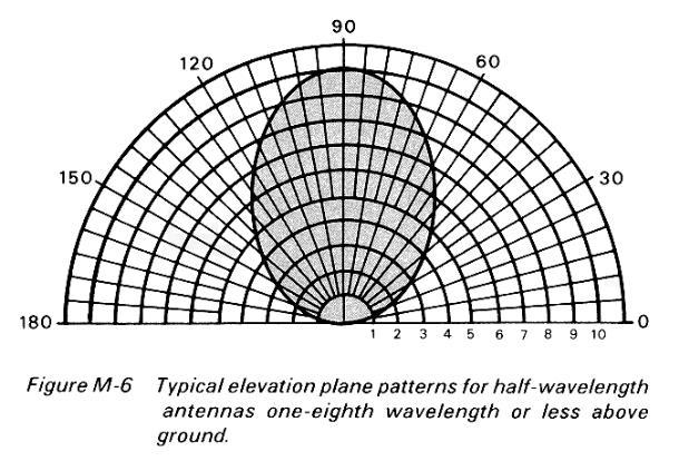
4 What Is NVIS? NVIS, or Near Vertical Incidence Skywave, refers to a radio propagation mode which involves the use of antennas with a very high radiation angle, approaching or reaching 90 degrees (straight up), along with selection of an appropriate frequency below the critical frequency, to establish reliable communications over a radius of miles or so, give or take 100 miles. 8/15/06 4
5

6 Propagation Considerations Propagation Considerations D layer losses Ionospheric scattering for vertical propagation Importance of critical frequency 8/15/06 6
7 NVIS is not an antenna, but a technique. Reliable communications between stations are based on three major factors.
8 Advantages of NVIS NVIS covers the area which is normally in the skip zone, that is, which is normally too far away to receive ground wave signals, but not yet far enough away to receive sky waves reflected from the ionosphere. 8/15/06 8
9 There is no skip zone unless you, the communicator, create it.
10
11 If you squirt a garden hose at the ceiling you can blanket a large area with water very effectively.
12
13 Advantages of NVIS NVIS requires no infrastructure such as repeaters or satellites. Two stations employing NVIS techniques can establish reliable communications without the support of any third party. NVIS techniques can dramatically reduce noise and interference, resulting in an improved signal/noise ratio. With its improved signal/noise ratio and low path loss, NVIS works well with low power. 8/15/06 13
14 Advantages of NVIS Pure NVIS propagation is relatively free from fading. Low areas and valleys are no problem for NVIS propagation. Antennas optimized for NVIS are usually low. Simple dipoles work very well. A good NVIS antenna can be erected easily, in a short amount of time, by a small team (or just one person). 8/15/06 14

15 NVIS HF radio systems played a key role for the Allied Forces during the D-Day invasion of Normandy in 1944.These techniques were incorporated into Signal support planning by Dr. H. H. Beverage.
16 USMC test proves NVIS highly reliable. 20 watts = 100% effectiveness in 200 mile radius
17 Antenna Height
18 NVIS Deployment One of the most effective antennas for NVIS is a dipole positioned from.1 to.25 wavelengths (or lower) above ground. Heights of 5 to 10 feet above ground are not unusual for NVIS setups. The inverted vee is another good NVIS antenna so long as the apex angle is kept gentle--about 120 degrees or greater. 8/15/06 18
19
20
21 Frequency
22 NVIS Deployment Typical frequency ranges used for NVIS are usually between 2.0 and 10 MHz. 40m amateur band for daytime and 75/80m for nighttime communications. The new 60m band with it s power & antenna limitations can be very effective using NVIS techniques. Desired modes are SSB, RTTY and PACTOR. 8/15/06 22
23

24 Power Level
25 NVIS Deployment With its improved signal/noise ratio and low path loss, NVIS works well with low power watts portable stations have a very high reliability factor making them very favorable for emergency or clandestine operation. Low power stations can run RTTY at 100% duty cycle. NVIS stations can generally be of the 100 watt variety. 8/15/06 25
26 NVIS Conclusions By steering the take off angle of your signal, HF communications can be extremely reliable for the long haul, medium haul and short haul. NVIS and high angle waves are very effective for ranges of 200 to 300 miles and out to 800 miles. No need for third party support such as repeaters or satellites. 8/15/06 26
27 NVIS Conclusions NVIS is effective in any terrain. Because of low S/N ratio NVIS is good for RTTY, PACTOR and SSB. NVIS is easy to deploy and very portable. 8/15/06 27
28 Stuff To Checkout Here are some areas that might be of interest to those that would like to learn more about NVIS This book is a must have. Near Vertical Incidence Skywave Communication, by David Fiedler and Edward Farmer, Oct 1996, $14.00, from WORLDRADIO Books, PO Box , Sacramento, CA It can be ordered on line as well at Amazon.com Here are some websites of interest SGC makes some very rugged and portable gear This is the NVIS reflector
NVIS. Near Vertical Incident Skywave. Norm Fusaro, W3IZ 05/19/2007 1
 NVIS Near Vertical Incident Skywave Norm Fusaro, W3IZ 05/19/2007 1 Introduction What Is NVIS? What are the advantages of NVIS? How to deploy NVIS. 05/19/2007 2 What Is NVIS? NVIS, or Near Vertical Incidence
Emergency Antennas VHF / UHF - FM. HF Voice, CW, or Digital
 1 Emergency Antennas VHF / UHF - FM HF Voice, CW, or Digital 2 Antennas for VHF Quarter Wave Vertical Half Wave Vertical Vertical Dipole J-Pole 3 Design Parameters Primarily line of sight Mounted on trunk
NVIS. Norm Fusaro, W3IZ 7/25/2007 2
 7/25/2007 1 NVIS Near Vertical Incident Skywave Norm Fusaro, W3IZ 7/25/2007 2 Introduction What Is NVIS? Advantages of NVIS? How to deploy NVIS. 7/25/2007 3 What Is NVIS? Near Vertical Incidence Skywave:
NVIS, Another Look. Tom Sanders, W6QJI Ed Bruette, N7NVP
 NVIS, Another Look Tom Sanders, W6QJI Ed Bruette, N7NVP Regional Communications N.V.I.S. Near Vertical Incidence Skywave What is NVIS? Near Vertical Incident Skywave Cloud Warmer Propagation Theory NVIS
Newspaper cartoon from the early 60 s
 Newspaper cartoon from the early 60 s NVIS for Emergency Communications Ross Mazzola Monroe County (NY) ARES Why NVIS? Damage to Infrastructure Inoperative Towers & Repeater Sites Loss of Backup Power
Clackamas Amateur Radio Emergency Services (CARES)
") Presented by: Clackamas Amateur Radio Emergency Services (CARES) 4/25/2015 1 NVIS Near Vertical Incident Skywave 4/25/2015 2 Introduction In this class the basic techniques in the theory, use, and making
Presented by: Clackamas Amateur Radio Emergency Services (CARES) 4/25/2015 1 NVIS Near Vertical Incident Skywave 4/25/2015 2 Introduction In this class the basic techniques in the theory, use, and making
Antennas and Propagation Chapters T4, G7, G8 Antenna Fundamentals, More Antenna Types, Feed lines and Measurements, Propagation
 Antennas and Propagation Chapters T4, G7, G8 Antenna Fundamentals, More Antenna Types, Feed lines and Measurements, Propagation =============================================================== Antenna Fundamentals
SB-400 HF Antennas SB-400
 SB-400 HF Antennas SB-400 The SB-400 Series of antennas are man-portable and rapid-deployable for HF communications. The HF ANTENNA communication mode is for paths from 10 to 400 km. This communication
Chapter 5.0 Antennas Section 5.1 Theory & Principles
 Chapter 5.0 Antennas Section 5.1 Theory & Principles G3C11 (B) p.135 Which of the following antenna types will be most effective for skip communications on 40-meters during the day? A. A vertical antenna
A Review of WICEN HF Communications Capability
 A Review of WICEN HF Communications Capability Abstract During a recent event, some problems were experienced with the traditional lower HF band communications often used for WICEN events. This paper describes
Chapter 7 HF Propagation. Ionosphere Solar Effects Scatter and NVIS
 Chapter 7 HF Propagation Ionosphere Solar Effects Scatter and NVIS Ionosphere and Layers Radio Waves Bent by the Ionosphere Daily variation of Ionosphere Layers Ionospheric Reflection Conduction by electrons
User Guide for the Alpha Antenna 6 40 or meter OCF Dipole
 User Guide for the Alpha Antenna 6 40 or 10 80 meter OCF Dipole Manufactured by: Alpha Antenna 1.888.482.3249 Website: http://alphaantenna.com User Guide Version 3.0 March 23, 2018 Page 1 Table of Contents
Compact Multi-Band Rotatable Dipole Antenna Array
 Compact Multi-Band Rotatable Dipole Antenna Array Dr. John A. Allocca, WB2LUA, www.wb2lua.com, 4/9/12 Introduction Having limited space led to the design of this multi-band antenna array, which has a foot
4/29/2012. General Class Element 3 Course Presentation. Radio Wave Propagation. Radio Wave Propagation. Radio Wave Propagation.
 General Class Element 3 Course Presentation ti ELEMENT 3 SUB ELEMENTS General Licensing Class Subelement G3 3 Exam Questions, 3 Groups G1 Commission s Rules G2 Operating Procedures G3 G4 Amateur Radio
NEWSLETTER DI-DAH-DI-DAH-DIT. Mercury Amateur Radio Association - MARA - North America - North East OTHER STUFF CONTENTS
 NEWSLETTER FEBRUARY 2009 VOLUME 9, No. 2 Mercury Amateur Radio Association - MARA - North America - North East CONTENTS VIEW FROM THE TOWER 2 ADVENTURES OF A NEW HAM - PART 4 2 PROPAGATION BETWEEN NOT-TOO-CLOSE
Lesson 12: Signal Propagation
 Lesson 12: Signal Propagation Preparation for Amateur Radio Technician Class Exam Topics HF Propagation Ground-wave Sky-wave Ionospheric regions VHF/UHF Propagation Line-of-sight Tropospheric Bending and
3 Methods of radiocommunication
 + + & & * * ) ) From the ITU Emergency Telecommunications handbook; prepared for the 54 th JOTA 2011. 3 Methods of radiocommunication 3.1 Frequencies Radio frequencies should be selected according to propagation
4/29/2012. General Class Element 3 Course Presentation. Ant Antennas as. Subelement G9. 4 Exam Questions, 4 Groups
 General Class Element 3 Course Presentation ti ELEMENT 3 SUB ELEMENTS General Licensing Class Subelement G9 Antennas and Feedlines 4 Exam Questions, 4 Groups G1 Commission s Rules G2 Operating Procedures
User Guide for the Alpha FMJ (Full Metal Jacket) Portable HF Antenna
 Portable HF Antenna") User Guide for the Alpha FMJ (Full Metal Jacket) Portable HF Antenna Manufactured by: Alpha Antenna 1.888.482.3249 Website: http://alphaantenna.com User Guide Version 3.1 October 18, 2018 Page 1 Table
User Guide for the Alpha FMJ (Full Metal Jacket) Portable HF Antenna Manufactured by: Alpha Antenna 1.888.482.3249 Website: http://alphaantenna.com User Guide Version 3.1 October 18, 2018 Page 1 Table
Maximum Usable Frequency
 Maximum Usable Frequency 15 Frequency (MHz) 10 5 0 Maximum Usable Frequency Usable Frequency Window Lowest Usable Frequency Solar Flare 6 12 18 24 Time (Hours) Radio Blackout Usable Frequency Window Ken
Technical and operational characteristics of land mobile MF/HF systems
 Recommendation ITU-R M.1795 (03/2007) Technical and operational characteristics of land mobile MF/HF systems M Series Mobile, radiodetermination, amateur and related satellite services ii Rec. ITU-R M.1795
Amateur Radio License. Propagation and Antennas
 Amateur Radio License Propagation and Antennas Todays Topics Propagation Antennas Propagation Modes Ground wave Low HF and below, ground acts as waveguide Line-of-Sight (LOS) VHF and above, radio waves
APPENDIX D COMMUNICATIONS
 APPENDIX D COMMUNICATIONS LRSU mission success depends on the LRS team s ability to report intelligence gathered. An LRS team that can see everything and report nothing is useless. LRSUs normally use high-frequent
NEAR VERTICAL INCIDENCE SKYWAVE COMMUNICATION. Antony Wedgwood, G0TJD. Introduction. The basics. Frequency selection. The VMARS Newsletter Issue 16
 NEAR VERTICAL INCIDENCE SKYWAVE COMMUNICATION Antony Wedgwood, G0TJD Introduction Over the last few months, there have been a number of references to Near Vertical Incidence Skywave (NVIS) communication.
Low Power Wireless monitoring of pest control systems to improve the efficiency of field workers.
 Introduction Low Power monitoring of pest control systems to improve the efficiency of field workers. Sponsored by Landcare. Part of the Strategic Technologies for Pest Control project funded by MBIE.
Regional and Long Distance Skywave Communications
 Regional and Long Distance Skywave Communications F LAYER SKYWAVE ELEVATION ANGLE STATION - A STATION - B Ken Larson KJ6RZ October 2010 1 Page Title 3 1.0 Introduction 3 2.0 The Earth s Ionosphere 6 3.0
Introduction to HF Propagation. Rick Fletcher, W7YP FVARC November 20, 2018
 Introduction to HF Propagation Rick Fletcher, W7YP FVARC November 20, 2018 Topics The HF Bands How HF propagation works Overview by HF band Sources of solar and propagation information Working HF during
Lighthouse Program: Neighbors Helping Neighbors
 Lighthouse Program: Neighbors Helping Neighbors What is the Lighthouse Program? A citizen-driven initiative to prepare for potential emergency or disaster conditions that include a reduction or loss of
Discover the Magic Of. HF Radio
 Discover the Magic Of HF Radio Welcome to Worldwide Communications This presentation is designed to introduce the new or recently upgraded ham to HF radio. Welcome to Worldwide Communications The information
The Fabulous Dipole. Ham Radio s Most Versatile Antenna
 The Fabulous Dipole Ham Radio s Most Versatile Antenna 1 What is a Dipole? Gets its name from its two halves One leg on each side of center Each leg is the same length It s a balanced antenna The voltages
NVIS PROPAGATION THEORY AND PRACTICE
 NVIS PROPAGATION THEORY AND PRACTICE Introduction Near-Vertical Incident Skywave (NVIS) propagation is a mode of HF operation that utilizes a high angle reflection off the ionosphere to fill in the gap
High Frequency Propagation (and a little about NVIS)
") High Frequency Propagation (and a little about NVIS) Tom McDermott, N5EG August 18, 2010 September 2, 2010 Updated: February 7, 2013 The problem Radio waves, like light waves, travel in ~straight lines.
High Frequency Propagation (and a little about NVIS) Tom McDermott, N5EG August 18, 2010 September 2, 2010 Updated: February 7, 2013 The problem Radio waves, like light waves, travel in ~straight lines.
Sw earth Dw Direct wave GRw Ground reflected wave Sw Surface wave
 WAVE PROPAGATION By Marcel H. De Canck, ON5AU Electromagnetic radio waves can propagate in three different ways between the transmitter and the receiver. 1- Ground waves 2- Troposphere waves 3- Sky waves
VHF/UHF Beyond FM Bob Witte KØNR Page 1
 VHF/UHF Beyond FM Technical Coordinator Colorado Section Page 1 Objective The objective of this presentation is to provide an introduction to operating on VHF/UHF, going beyond the usual FM / Repeater
Vertical or horizontal antenna for limited space
 Vertical or horizontal antenna for limited space If you have very limited space for a DX antenna, you may consider vertical, because it has low angle of radiation. But vertical polarization involves high
Chapter 6 Propagation
 Chapter 6 Propagation Al Penney VO1NO Objectives To become familiar with: Classification of waves wrt propagation; Factors that affect radio wave propagation; and Propagation characteristics of Amateur
Saurabh Sanghai (1) *, Maxim Ignatenko (1), Kim Hassett (2) and Dejan S. Filipović (1)
 *, Maxim Ignatenko (1), Kim Hassett (2) and Dejan S. Filipović (1)") Antenna Measurement Techniques Association 36 th Annual Meeting and Symposium October 12-17, 2014 Saurabh Sanghai (1) *, Maxim Ignatenko (1), Kim Hassett (2) and Dejan S. Filipović (1) (1) University of
Antenna Measurement Techniques Association 36 th Annual Meeting and Symposium October 12-17, 2014 Saurabh Sanghai (1) *, Maxim Ignatenko (1), Kim Hassett (2) and Dejan S. Filipović (1) (1) University of
Transforms and electrical signal into a propagating electromagnetic wave OR vise versa. - Transducer goes both ways. TX and RX antennas have
 Gary Rondeau AF7NX Transforms and electrical signal into a propagating electromagnetic wave OR vise versa. - Transducer goes both ways. TX and RX antennas have different jobs. For TX want to generate as
Chapter 3 Antennas. Section I. Antenna Selection FM 24-19
 Chapter 3 Antennas One of the most important considerations when operating a radio is the type of antenna to be used. For good communications with a radio operating in the HF range (2.000 khz to 29.999
right during the VE Session Have fun Bob, KA9BH Eric, K9VIC
 Radio Wave Propagation Teach you enough to get all right during the VE Session Learn a few things from you Have fun Finish everything on time (if the propagation questions about your experiences not a
Tactical Dipole (CHA TD) Operator s Manual
 Operator s Manual") Tactical Dipole (CHA TD) Operator s Manual California - USA WWW.CHAMELEONANTENNA.COM VERSATILE DEPENDABLE STEALTH BUILT TO LAST Table of Contents Introduction... 3 HF Propagation... 3 Parts of the Antenna...
Tactical Dipole (CHA TD) Operator s Manual California - USA WWW.CHAMELEONANTENNA.COM VERSATILE DEPENDABLE STEALTH BUILT TO LAST Table of Contents Introduction... 3 HF Propagation... 3 Parts of the Antenna...
Summary of Findings Associated with the 5 MHz Experiment. Marcus C. Walden G0IJZ Space Weather Knowledge Exchange Workshop: HAMSCI UK 13 October 2017
 Summary of Findings Associated with the 5 MHz Experiment Marcus C. Walden G0IJZ Space Weather Knowledge Exchange Workshop: HAMSCI UK 13 October 2017 Overview of Presentation Introduction The 5 MHz Experiment
Chapter 6 Antenna Basics. Dipoles, Ground-planes, and Wires Directional Antennas Feed Lines
 Chapter 6 Antenna Basics Dipoles, Ground-planes, and Wires Directional Antennas Feed Lines Some General Rules Bigger is better. (Most of the time) Higher is better. (Most of the time) Lower SWR is better.
Beams and Directional Antennas
 Beams and Directional Antennas The Horizontal Dipole Our discussion in this chapter is about the more conventional horizontal dipole and the simplified theory behind dipole based designs. For clarity,
# DEFINITIONS TERMS. 2) Electrical energy that has escaped into free space. Electromagnetic wave
 Electrical energy that has escaped into free space. Electromagnetic wave") CHAPTER 14 ELECTROMAGNETIC WAVE PROPAGATION # DEFINITIONS TERMS 1) Propagation of electromagnetic waves often called radio-frequency (RF) propagation or simply radio propagation. Free-space 2) Electrical
CHAPTER 14 ELECTROMAGNETIC WAVE PROPAGATION # DEFINITIONS TERMS 1) Propagation of electromagnetic waves often called radio-frequency (RF) propagation or simply radio propagation. Free-space 2) Electrical
Pacific Telecommunications Conference 2017
 Pacific Telecommunications Conference 2017 2017 product and connectivity update NVIS Communications, Barrett Communications, Star Solutions, and now REDCOM Laboratories Failover versus Fallback for telecomm
Terry G. Glagowski W1TR / AFA1DI
 The Ionogram and Radio Propagation By Terry G. Glagowski / W1TR / AFA1DI - 9/29/2017 9:46 AM Excerpts from a presentation by Tom Carrigan / NE1R / AFA1ID by Terry G. Glagowski W1TR / AFA1DI Knowledge of
Tactical Dipole (CHA TD) Operator s Manual
 Operator s Manual") Tactical Dipole (CHA TD) Operator s Manual California - USA WWW.CHAMELEONANTENNA.COM VERSATILE DEPENDABLE STEALTH BUILT TO LAST Table of Contents Introduction... 3 HF Propagation... 3 Parts of the Antenna...
Tactical Dipole (CHA TD) Operator s Manual California - USA WWW.CHAMELEONANTENNA.COM VERSATILE DEPENDABLE STEALTH BUILT TO LAST Table of Contents Introduction... 3 HF Propagation... 3 Parts of the Antenna...
Chapter 15: Radio-Wave Propagation
 Chapter 15: Radio-Wave Propagation MULTIPLE CHOICE 1. Radio waves were first predicted mathematically by: a. Armstrong c. Maxwell b. Hertz d. Marconi 2. Radio waves were first demonstrated experimentally
RECOMMENDATION ITU-R F Characteristics of HF fixed radiocommunication systems
 Rec. ITU-R F.1761 1 RECOMMENDATION ITU-R F.1761 Characteristics of HF fixed radiocommunication systems (Question ITU-R 158/9) (2006) Scope This Recommendation specifies the typical RF characteristics of
2013 Illinois QSO Party. A Gravel Road Less Traveled. AH6EZ/W9 October 20, 2013
 2013 Illinois QSO Party A Gravel Road Less Traveled AH6EZ/W9 October 20, 2013 What is the Illinois QSO Party? October contest focused on Illinois One of many state QSO Parties IL QSO Party is a single
CHAPTER 9 HIGH FREQUENCY RADIO OPERATION CHAPTER
 SECTION 2 ESTABLISHMENT, MAINTENANCE AND OPERATION OF COMMUNICATION SYSTEMS AND EQUIPMENT CHAPTER 9 HIGH FREQUENCY RADIO OPERATION CHAPTER 9 9.1 COMPLEXITIES AND VARIABLES The operation of High Frequency
S.R.M. Institute of Science & Technology Deemed University School of Electronics & Communication Engineering
 S.R.M. Institute of Science & Technology Deemed University School of Electronics & Communication Engineering Question Bank Subject Code : EC401 Subject Name : Antennas and Wave Propagation Year & Sem :
Discover the Magic. Revision 2. HF Radio
 Discover the Magic Revision 2 Of HF Radio Welcome to Worldwide Communications This presentation is designed to introduce the new or recently upgraded ham to HF radio, and has been modified for the Canadian
ANTENNA THEORY WAVE PROPAGATION HF ANTENNAS
 ANTENNA THEORY WAVE PROPAGATION & HF ANTENNAS FREQUENCY SPECTRUM INFORMATION Frequency range American designator below 300 Hz..ELF (extremely Low Frequency) 300-3000 Hz..ILF (Intermediate Low Frequency)
The vertical antenna at W5CSU, constructed of 4 inch down-spouting - 40 feet high - usable on 20, 40, and 80 meters.
 The Truth About the Vertical Antenna Measured and Calculated Performance Compared with an Ideal Horizontal Antenna By B. W. Griffith - W5CSU May 1952 QST No one antenna will do all sorts of jobs equally
Space Weather and Propagation JANUARY 14, 2017
 Space Weather and Propagation MARTIN BUEHRING -KB4MG ELEC T R ICAL ENGINEER, A M AT EUR EXTRA CLASS LICENSE HOLDER JANUARY 14, 2017 Why know about Space Weather? Our SUN has an enormous affect not only
1. What are the applications of loop antenna? (May2011) 2. Define Pattern Multiplication (May2011)
 2. Define Pattern Multiplication (May2011)") UNIT-II WIRE ANTENNAS AND ANTENNA ARRAYS 1. What are the applications of loop antenna? (May2011) 2. Define Pattern Multiplication (May2011) 3. A uniform linear array contains 50 isotropic radiation with
UNIT-II WIRE ANTENNAS AND ANTENNA ARRAYS 1. What are the applications of loop antenna? (May2011) 2. Define Pattern Multiplication (May2011) 3. A uniform linear array contains 50 isotropic radiation with
General License Class Chapter 6 - Antennas. Bob KA9BHD Eric K9VIC
 General License Class Chapter 6 - Antennas Bob KA9BHD Eric K9VIC Learning Objectives Teach you enough to get all the antenna questions right during the VE Session Learn a few things from you about antennas
UNIT Derive the fundamental equation for free space propagation?
 UNIT 8 1. Derive the fundamental equation for free space propagation? Fundamental Equation for Free Space Propagation Consider the transmitter power (P t ) radiated uniformly in all the directions (isotropic),
Reading 28 PROPAGATION THE IONOSPHERE
 Reading 28 Ron Bertrand VK2DQ http://www.radioelectronicschool.com PROPAGATION THE IONOSPHERE The ionosphere is a region of the upper atmosphere extending from a height of about 60 km to greater than 500
Basic Wire Antennas. Part II: Loops and Verticals
 Basic Wire Antennas Part II: Loops and Verticals A loop antenna is composed of a single loop of wire, greater than a half wavelength long. The loop does not have to be any particular shape. RF power can
EMCOMM III Base Antenna Operator s Manual
 EMCOMM III Base Antenna Operator s Manual Nevada - USA WWW.CHAMELEONANTENNA.COM VERSATILE DEPENDABLE STEALTH BUILT TO LAST Table of Contents Introduction... 3 HF Propagation... 3 Parts of the Antenna...
Traveling Wave Antennas
 Traveling Wave Antennas Antennas with open-ended wires where the current must go to zero (dipoles, monopoles, etc.) can be characterized as standing wave antennas or resonant antennas. The current on these
ANOTHER MULTIBAND WIRE ANTENNA
 ANOTHER MULTIBAND WIRE ANTENNA Above The multiband long wire with balun (cover is off) by Ron VK3AFW. I wanted to build a simple wire antenna dedicated to 30 m and 17m for operation during the 2015 ILLW
Antennas and Propagation. Chapter 5
 Antennas and Propagation Chapter 5 Introduction An antenna is an electrical conductor or system of conductors Transmission - radiates electromagnetic energy into space Reception - collects electromagnetic
Properties and Performance of a New Compact HF Aerial Design for Multi-Band Operation D. Telfer, J. Spencer
 Properties and Performance of a New Compact HF Aerial Design for Multi-Band Operation D. Telfer, J. Spencer This work is an extension to that of Telfer and Austin [1] in that here a balanced feed embodiment
Antennas and Propagation. Chapter 5
 Antennas and Propagation Chapter 5 Introduction An antenna is an electrical conductor or system of conductors Transmission - radiates electromagnetic energy into space Reception - collects electromagnetic
4/18/2012. Supplement T3. 3 Exam Questions, 3 Groups. Amateur Radio Technician Class
 Amateur Radio Technician Class Element 2 Course Presentation ti ELEMENT 2 SUB-ELEMENTS Technician Licensing Class Supplement T3 Radio Wave Characteristics 3 Exam Questions, 3 Groups T1 - FCC Rules, descriptions
14. COMMUNICATION SYSTEM
 14. COMMUNICATION SYSTEM SYNOPSIS : INTRODUCTION 1. The exchange of information between a sender and receiver is called communication. 2. The arrangement of devices to transfere the information is called
Antennas and Propagation
 CMPE 477 Wireless and Mobile Networks Lecture 3: Antennas and Propagation Antennas Propagation Modes Line of Sight Transmission Fading in the Mobile Environment Introduction An antenna is an electrical
Magnetic Loop Antenna - Topbands
 Magnetic Loop Antenna - Topbands Instruction Manual Thank you for purchasing this new product small Magnetic Loop Antenna Topbands. Manual contains important information. Please read all instructions carefully
Portable Wire Antennas PDF
 Portable Wire Antennas PDF Second Edition - March 31, 2015-10 additional chapters added including information on traveling wave antennas, directional broadband antennas, long wire antennas, high signal
Q-MAC Launches New Antenna to revolutionise Vehicle HF communications.
 Q-MAC Launches New Antenna to revolutionise Vehicle HF communications. Perth, Australia Leading designer and manufacturer of HF transceivers Q-MAC Electronics in Perth Western Australia has unveiled it
Polarization orientation of the electric field vector with respect to the earth s surface (ground).
.") Free space propagation of electromagnetic waves is often called radio-frequency (rf) propagation or simply radio propagation. The earth s atmosphere, as medium introduces losses and impairments to the
Free space propagation of electromagnetic waves is often called radio-frequency (rf) propagation or simply radio propagation. The earth s atmosphere, as medium introduces losses and impairments to the
HF Faraday Loop Antenna (CHA F-LOOP) Operator s Manual
 Operator s Manual") HF Faraday Loop Antenna (CHA F-LOOP) Operator s Manual California - USA WWW.CHAMELEONANTENNA.COM VERSATILE DEPENDABLE STEALTH BUILT TO LAST Table of Contents Introduction... 3 HF Propagation... 3 Parts
HF Faraday Loop Antenna (CHA F-LOOP) Operator s Manual California - USA WWW.CHAMELEONANTENNA.COM VERSATILE DEPENDABLE STEALTH BUILT TO LAST Table of Contents Introduction... 3 HF Propagation... 3 Parts
The EMCOMM Easytenna
 The EMCOMM Easytenna This document will detail how to build an easy to install multiband dipole type antenna for emergency communications using the NVIS propagation mode. History The NVIS mode is one in
ANTENNA BASICS FOR BEGINNERS
 ANTENNA BASICS FOR BEGINNERS PART 2 -DIPOLES DIPOLES -General MULTIBAND DIPOLES RF CHOKES 1 DIPOLES Several different variations of the dipole are also used, such as the folded dipole, short dipole, cage
Weak-Signal Radio Communications for Bitcoin Network Resilience. Nick Szabo, Elaine Ou globalfinancialaccess.com Scaling Bitcoin 2017
 Weak-Signal Radio Communications for Bitcoin Network Resilience Nick Szabo, Elaine Ou globalfinancialaccess.com Scaling Bitcoin 2017 What is Weak-Signal HF Radio? Radio transmission using shortwave frequencies
Study of Factors which affect the Calculation of Co- Channel Interference in a Radio Link
 International Journal of Electronic and Electrical Engineering. ISSN 0974-2174 Volume 8, Number 2 (2015), pp. 103-111 International Research Publication House http://www.irphouse.com Study of Factors which
General Classs Chapter 7
 General Classs Chapter 7 Radio Wave Propagation Bob KA9BHD Eric K9VIC Learning Objectives Teach you enough to get all the propagation questions right during the VE Session Learn a few things from you about
Antennas! November 2018
 1 Antennas! November 2018 Agenda 6PM Show and Tell plus Demos in the Park 7PM Welcome: new members and visitors Announcements Antenna Overview Alpha Loop Antenna N6IET Vertical Colinear WB6MMQ Whip Dipole
Portable Magnetic Loop Antenna. KG5EAO Rick Bono
 Portable Magnetic Loop Antenna KG5EAO Rick Bono April 2, 2016 Overview Develop a Portable magnetic loop antenna for use on HF bands running QRP. Portable and easy to deploy Ideally run on the 40m through
HFIA The year to finally integrate HF with all primary systems
 HFIA - 2017 The year to finally integrate HF with all primary systems Barrett 4050 HF Software Defined Radio with IP, IMAP, and Wi-Fi. Deployable systems with integrated microcells, C4/C5 software switching,
Chapter 13: Wave Propagation. EET-223: RF Communication Circuits Walter Lara
 Chapter 13: Wave Propagation EET-223: RF Communication Circuits Walter Lara Electrical to Electromagnetic Conversion Since the atmosphere is not a conductor of electrons (instead a good insulator), electrical
Electric and Magnetic Fields Near Physically Large Radiators
 Electric and Magnetic Fields Near Physically Large Radiators 1. Overview Author: Ed Hare, ARRL Laboratory Manager 1 Date: July 7, 2003 1.1 Making measurements of electric and magnetic field strength requires
Chapter-15. Communication systems -1 mark Questions
 Chapter-15 Communication systems -1 mark Questions 1) What are the three main units of a Communication System? 2) What is meant by Bandwidth of transmission? 3) What is a transducer? Give an example. 4)
General Class License Theory III. Dick Grote K6PBF
 General Class License Theory III Dick Grote K6PBF K6pbfdick@gmail.com 1 Introduction In this session we will learn about: Feed Lines Antennas Safety As in the other theory classes, we will try to present
A first study into the propagation of 5 MHz (60 m) signals using the South African ionosonde network
 signals using the South African ionosonde network") A first study into the propagation of 5 MHz (60 m) signals using the South African ionosonde network Hannes Coetzee, B. Eng. (Electronics), M. Sc. (Physics), ZS6BZP The SARL has purchased two 5 MHz test
A first study into the propagation of 5 MHz (60 m) signals using the South African ionosonde network Hannes Coetzee, B. Eng. (Electronics), M. Sc. (Physics), ZS6BZP The SARL has purchased two 5 MHz test
HF Skywave ITU-R P Gets a Re-Write. July Pierre Missud Avadh Nandra. RF Modeling with Precision
 HF Skywave ITU-R P.533-9 Gets a Re-Write July 2008 Pierre Missud Avadh Nandra RF Modeling with Precision 0 0 HF Skywave ITU-R P. 533-9 gets a re-write HF skywave propagation was introduced to this world
Data Communication Prof. Ajit Pal Department of Computer Science & Engineering Indian Institute of Technology, Kharagpur Lecture No # 6 Unguided Media
 Data Communication Prof. Ajit Pal Department of Computer Science & Engineering Indian Institute of Technology, Kharagpur Lecture No # 6 Unguided Media Hello and welcome to today s lecture on unguided media.
Technician Licensing Class T9
 Technician Licensing Class T9 Amateur Radio Course Monroe EMS Building Monroe, Utah January 11/18, 2014 January 22, 2014 Testing Session Valid dates: July 1, 2010 June 30, 2014 Amateur Radio Technician
A Practical NVIS Antenna for Emergency or Temporary Communications
 A Practical NVIS Antenna for Emergency or Temporary Communications Rev. 0 Optimum for 40 and 80 Meters DX Engineering 2008 P.O. Box 1491 Akron, OH 44309-1491 Phone: (800) 777-0703 Tech Support and International:
Ionospheric Sounders What are they? How can you use them?
 Ionospheric Sounders What are they? How can you use them? History of the ionosphere Jan. 1901 Marconi sends signals from Isle of Wight to The Lizard, Cornwall Dec. 1901 Marconi crosses Atlantic, from Poldhu
One I had narrowed the options down, I installed some wire and started testing.
 Loft & Attic antennas for restricted spaces - M. Ehrenfried G8JNJ I ve recently been looking at designs for an efficient antenna that would fit in a loft. I hoped to find something that would work on with
January 16, 2011 Scott Burgett, Bronson Hokuf Garmin International, Olathe, Kansas
 Experimental Evidence of Wide Area GPS Jamming That Will Result from LightSquared s Proposal to Convert Portions of L Band 1 to High Power Terrestrial Broadband Executive Summary January 16, 2011 Scott
SPECIAL EVENT. Club Officers: The Official Monthly Journal of the Tusco Amateur Radio Club. W8ZX repeater committee testing the new D-Star repeaters.
 The Official Monthly Journal of the Tusco Amateur Radio Club Volume 31, Issue 10 Celebrating 69 Years of Service October 2008 Club Officers: PRESIDENT Gary Green K8WFN VICE PRESIDENT Paul Truchly AA8WQ
Channel Modeling and Characteristics
 Channel Modeling and Characteristics Dr. Farid Farahmand Updated:10/15/13, 10/20/14 Line-of-Sight Transmission (LOS) Impairments The received signal is different from the transmitted signal due to transmission
Chapter 4 The RF Link
 Chapter 4 The RF Link The fundamental elements of the communications satellite Radio Frequency (RF) or free space link are introduced. Basic transmission parameters, such as Antenna gain, Beamwidth, Free-space
RF Propagation. By Tim Kuhlman, PE KD7RUS
 RF Propagation By Tim Kuhlman, PE KD7RUS Purpose of this Seminar In this seminar we will attempt to answer the following questions: What is RF propagation? What are the different types of propagation?