Terry G. Glagowski W1TR / AFA1DI
|
|
|
- Posy Gibbs
- 6 years ago
- Views:
Transcription


1 The Ionogram and Radio Propagation By Terry G. Glagowski / W1TR / AFA1DI - 9/29/2017 9:46 AM Excerpts from a presentation by Tom Carrigan / NE1R / AFA1ID by Terry G. Glagowski W1TR / AFA1DI Knowledge of Radio Propagation is important to the operations of HF MARS nets. It enables the NCS to choose the proper frequency so that the net can reach the most stations. If the chosen frequency is too high, skip zones may prevent reaching close in stations. If the chosen frequency is too low, distant stations may be weak or unreadable. Radio checks on the alternative frequencies is the best indication of useable propagation. Use of Ionograms created by Digisondes can help in deciding the proper frequency. When the Internet is available, Ionograms can be viewed online at various sites.
2 Radio Propagation Ground Wave Skywave NVIS Ionosphere Layers Creation of Ionosphere D Layer: Absorption E Layer: Sporadic Es Skywave F Layers: F1, F2 Primary Skywave FoF2 Critical Frequency: NVIS MUF Maximum Useable Frequency: DX Solar Behavior 11 year Sunspot Cycles SSN SFI A Index K Index Solar Flares, CME Ionogram Digisondes generate Ionograms Interpretation of the Ionogram How to Choose Net Frequency Geography MUF and FoF2 Introduction

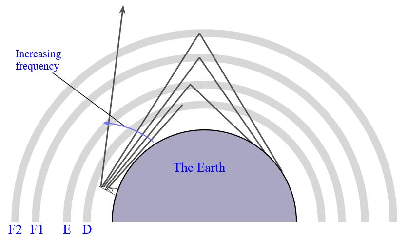
3 Radio Propagation Freq > MUF Maximum Frequency Reflected by Ionosphere Critical Frequency FoF2 = MUF For NVIS Freq < MUF

4 Ionospheric Layers

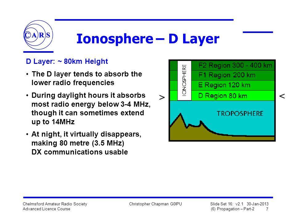
5 Ionospheric Layers D Layer 0-5 mhz mhz 5-10 mhz
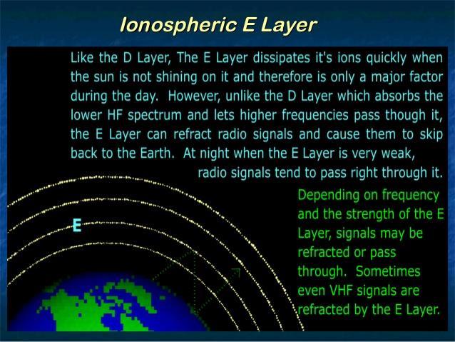
6 Ionospheric Layers E Layer mhz
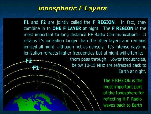
7 Ionospheric Layers F Layers
8 Ionospheric Layers Frequencies
9 Skywave Propagation Freq > MUF Freq < MUF NVIS when Skip Distance = 0, when F < FoF2 Critical Frequency

10 Solar Indices
11 Solar Indices
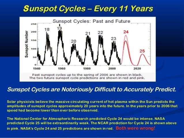
12 Sunspot Cycles

13 Geomagnetic A Index
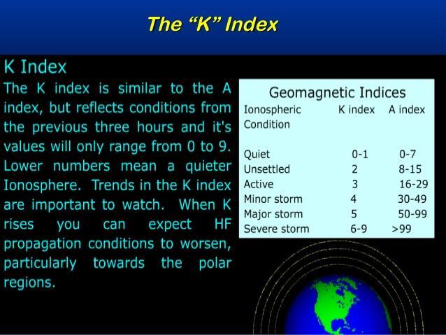
14 Geomagnetic K Index

15 CME Coronal Mass Ejection

16 Solar and Geomagnetic Indices

17 Digisonde Apparatus to generate Ionograms and calculate FoF2 and MUF
18 Ionogram - Notional

19 Ionogram - Legend
20 URSI Ionospheric Parameter Codes F Layer Parameters Ionogram - Terms Parameter Description fof2 F2 layer o-mode (ordinary) critical frequency. fxf2 F2 layer x-mode (extraordinary) critical frequency. fzf2 F2 layer z-mode critical frequency. M3000F2 F2 layer M factor (the ratio of the maximum usable frequency divided by the critical frequency). h'f2 F2 layer o-mode minimum virtual height. hpf2 An estimate of the true height of the F2 layer (measurement of the ordinary mode virtual height at a frequency of 83.4% of the fof2). h'ox F layer minmum virual height of the x-mode trace at a frequency equal to the fof2. MUF3000F2 F2 layer maximum usable frequency for 3000km path. fof1 F1 layer o-mode critical frequency. fxf1 F1 layer x-mode critical frequency h'f1 F1 layer o-mode minimum virtual height. h'f F layer o-mode minimum virual height. MUF3000F1 F1 layer maximum usable frequency(see code 07). E Layer Parameters Parameter Description foe E layer o-mode critical frequency. foe2 E2 layer o-mode critical frequency (when it occurs it is between the normal E and F1 layers). h'e E layer o-mode minmum virual height. h'e2 E2 layer o-mode minimum virtual height. Es Layer Parameters Parameter Description foes Es layer hightest o-mode frequency are which a mainly continuous Es trace is observed. fxe Es layer highest x-mode frequency are which a mainly continuous Es trace is observed. fbes The blanketing frequency of layer used to derive foes. ftes Top frequency of the Es trace (any mode).
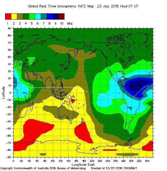
21 FoF2 Map 4 to 5 MHz
22 Ionogram - Actual FoF2 MUF F2 F2 Multiple F2 Reflections D Layer Absorption F2 FxF2 Extraordinary FoF2 FoF2 / MUF Indicate 2.5 MHz NVIS, Absorption? 3.3 MHz NVIS, Absorption? 4.6 MHz NVIS 5.8 MHz 700 KM Skip 7.6 MHz 1200 KM Skip E Layer may cause Absorption E Layer
23 How to Choose a Net Frequency Always Confirm Prediction with RADIO CHECK Before Net Region Nets Check Ionogram for FoF2 frequency Choose highest frequency <= FoF2, where there will be NO SKIP ZONE Division Nets (RGN 1,2,3) Determine the geographical region of the net operations Check the Ionogram to see what the FoF2 and skip distances will be Frequencies slightly higher than FoF2 will work somewhat due to ground wave If multiple Net Control Stations (NCS) are available then a small to moderate skip zone can be tolerated (less than 400 km) and therefore a somewhat higher frequency can be used During daytime, absorption by D and E layers can be a factor so using the highest workable frequency TransGlobal Net Choose a frequency less than the MUF for the geographical area but high enough to avoid absorption during the day by the D layer Check the Ionogram to see what the MUF, FoF2, and skip distances will be Since there will be a skip zone, multiple NCS stations will be required: West, East, and Central.

24 USAF MARS NE Division, Regions 1,2,3


25 NVIS vs DX Antennas NVIS Antenna High Angle of Radiation DX Antenna Low Angle of Radiation Vertical Low Dipole or Horizontal Loop Yagi
26 Propagation Sites A-Index, K-Index, SFI Summary CONUS HF Band Conditions NOAA Ionogram Millstone Hill Ionogram Wallops Is Ionogram Latest Ionograms Ionogram Explanation (Wikipedia) Understanding Ionograms G0LFP DX Maps Ionospheric Map Australian Space Weather Services Quick Guide to HF Propabation Using Solar Indices (N2LVI) HF Propagation Tools (N0NBH) K-Index (WikiPedia) Space Weather Prediction Center (NOAA) Space Weather (.com) Solar Ham - List of Ionosode Stations - FoF2 Map
27 Conclusion Many factors regarding solar conditions affect the ionosphere, and the magnetosphere, which affect radio propagation. Time of Day Day of Month (28 day rotation of sun) Time of Year Sunspot Cycle Solar Flares Geomagnetic Storms The best indication of good propagation is an actual radio check. Use of solar and geomagnetic indices and ionograms, can greatly aid in the choice of the best frequency for net operations.
28 Extra Slides
29 The Ionosphere The Ionosphere is a plasma shell of electrons, positive ions, and molecules that surrounds the earth The Ionosphere is created by ultraviolet radiation from the sun, which ionizes the molecules of the atmosphere Ionization is the process of ultraviolet photons transferring energy to a molecule, thereby causing the electron and the positive ion to separate Recombination is the reverse process, where a photon is emitted when an electron recombines with the positive ion randomly and spontaneously The electron density is determined by the relative ionization and recombination rates when they are in equilibrium The critical frequency is dependent on the electron density at any given region: latitude, longitude, altitude, of the ionosphere The maximum usable frequency for a given distance is dependent on the critical frequency and critical angle Factors affecting ionization include: Time of day (daylight vs darkness) Day of month (28 1/2 day solar rotation), sunspots, flares point towards or away from earth Time of year (summer vs winter vs fall and spring), amount of daylight and ionization Solar Cycle (solar flux, sunspot number) Solar Flares (unpredictable), proton and X-Ray events Solar Wind creating Geomagnetic Storms
30 Ionization and Recombination Ionization occurs with solar radiation (uv) ELECTRON NEUTRON PROTON PHOTON Photon energy is proportional to frequency, Inversely proportional to wavelength. Units are in electron volts. Energy ev = / wavelength um. Minimum energy of ultra violet wavelength Is needed to cause ionization. Ultraviolet is nm. Or ev. X-Rays have higher energy. Recombination occurs randomly, spontaneously proportional to density FREE ELECTRON ELECTRON NEUTRON PROTON FREE ELECTRON PHOTON

31 Ionospheric Layers Radio properties of the ionosphere, i.e. critical frequency, are determined by electron density, which is related to ionization rate, which depends on solar radiation.

32 Ionospheric Layers Heights


33 Multi-Hop Propagation (DX) Attenuation Proportional to Number of Hops Radiation Angle Affects DX Performance Fewer Hops
34 Multi-Path Propagation (QSB) Changing ionosphere location causes QSB fading Can be caused by magnetic storms
35 Sporadic-E VHF Propagation Also sometimes on 28 mhz and 144 mhz

36 Ionogram - Actual FoF2 MUF F2 Multiple F2 Reflections D Layer Absorption F2 FoF1 FoF2 Es Layer FoF2 / MUF Indicate 2.5 MHz NVIS, Absorption? 3.3 MHz NVIS 4.6 MHz NVIS 5.8 MHz 600 KM Skip 7.6 MHz 1100 KM Skip E Layer Small Skip Distance

37 Solar and Geomagnetic - Actual

38 Ionogram - Actual FoF2 MUF D Layer Absorption FoF2 / MUF Indicate 2.5 MHz NVIS, Absorption Low? 3.3 MHz NVIS, Absorption Low? 4.6 MHz NVIS 5.8 MHz NVIS 7.6 MHz 900 KM Skip E Layer may cause Absorption Es Layer E Layer Skip Distance
39 Ionogram - Actual Austin not NE FoF2 MUF F2 F2 Multiple F2 Reflections Es E FxF2 Extraordinary D Layer Absorption FoF2 Es Layer E Layer FoF2 / MUF Indicate 2.5 MHz NVIS, Absorption High? 3.3 MHz NVIS, Absorption High? 4.6 MHz NVIS, Absorption High? 5.8 MHz NVIS 7.6 MHz 500 KM Skip E Layer may cause Absorption
40 Ionogram - Actual FoF2? Es Layer MUF? D Layer Absorption? Very Few F Layer Reflections Insufficient Data for Digisonde to Calculate FoF2 and MUF E Layer may be blocking Es Layer Skip Distance?
41 Ionogram - Actual FoF2?? Es Layer MUF? Es D Layer Absorption 6 Meters Open? FoF2 / MUF Indicate 2.5 MHz NVIS, Absorption High? 3.3 MHz NVIS, Absorption High? 4.6 MHz NVIS, Absorption High? 5.8 MHz NVIS?, Short Skip, Long Skip, Some Attenuation 7.6 MHz 500 KM Skip? E Layer may cause Absorption and Short Skip Es Es Multiple Es Reflections Es Layer Skip Distance?
42 Ionogram - Actual FoF2 Es Layer MUF Es D Layer Absorption FoF2 / MUF Indicate 2.5 MHz NVIS, Absorption High? 3.3 MHz NVIS, Absorption High? 4.6 MHz NVIS, Absorption High? 5.8 MHz 500 KM Skip, Short Skip, Some Attenuation 7.6 MHz 1100 KM Skip? E Layer may cause Absorption and Short Skip Es Es Multiple Es Reflections Es Layer Skip Distance?
43 Ionogram - Actual FoF2 MUF F2 F2 Multiple Reflections D Layer Absorption FoF2 E Layer FoF2 / MUF Indicate 2.5 MHz NVIS, Absorption High? 3.3 MHz NVIS, Absorption High? 4.6 MHz NVIS 5.8 MHz 600 Skip E Layer may cause Absorption

44 NVIS Near Vertical Incident Skywave Typical NVIS Range Typical Ground Wave Range Courtesy: Tom Carrigan / NE1R / AFA1IR

45 Ionospheric Layers Resonant (Critical) frequency determined by electron density
46 Ionospheric Layers Resonant (Critical) frequency determined by electron density
47 Ionospheric Layers
48 Ionospheric Layers

49 Ionospheric Layers

50 Ionospheric Layers

51 Skywave Propagation NVIS when Skip Distance = 0, when F < FoF2
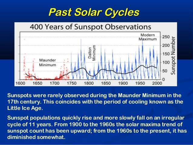
52 Sunspot Cycles

53 Sunspot Cycles
Chapter 7 HF Propagation. Ionosphere Solar Effects Scatter and NVIS
 Chapter 7 HF Propagation Ionosphere Solar Effects Scatter and NVIS Ionosphere and Layers Radio Waves Bent by the Ionosphere Daily variation of Ionosphere Layers Ionospheric Reflection Conduction by electrons
4/29/2012. General Class Element 3 Course Presentation. Radio Wave Propagation. Radio Wave Propagation. Radio Wave Propagation.
 General Class Element 3 Course Presentation ti ELEMENT 3 SUB ELEMENTS General Licensing Class Subelement G3 3 Exam Questions, 3 Groups G1 Commission s Rules G2 Operating Procedures G3 G4 Amateur Radio
NVIS PROPAGATION THEORY AND PRACTICE
 NVIS PROPAGATION THEORY AND PRACTICE Introduction Near-Vertical Incident Skywave (NVIS) propagation is a mode of HF operation that utilizes a high angle reflection off the ionosphere to fill in the gap
Space Weather and Propagation JANUARY 14, 2017
 Space Weather and Propagation MARTIN BUEHRING -KB4MG ELEC T R ICAL ENGINEER, A M AT EUR EXTRA CLASS LICENSE HOLDER JANUARY 14, 2017 Why know about Space Weather? Our SUN has an enormous affect not only
Chapter 6 Propagation
 Chapter 6 Propagation Al Penney VO1NO Objectives To become familiar with: Classification of waves wrt propagation; Factors that affect radio wave propagation; and Propagation characteristics of Amateur
High Frequency Propagation (and a little about NVIS)
") High Frequency Propagation (and a little about NVIS) Tom McDermott, N5EG August 18, 2010 September 2, 2010 Updated: February 7, 2013 The problem Radio waves, like light waves, travel in ~straight lines.
High Frequency Propagation (and a little about NVIS) Tom McDermott, N5EG August 18, 2010 September 2, 2010 Updated: February 7, 2013 The problem Radio waves, like light waves, travel in ~straight lines.
General Classs Chapter 7
 General Classs Chapter 7 Radio Wave Propagation Bob KA9BHD Eric K9VIC Learning Objectives Teach you enough to get all the propagation questions right during the VE Session Learn a few things from you about
Ionospheric Propagation
 Ionospheric Nick Massey VA7NRM 1 Electromagnetic Spectrum Radio Waves are a form of Electromagnetic Radiation Visible Light is also a form of Electromagnetic Radiation Radio Waves behave a lot like light
Maximum Usable Frequency
 Maximum Usable Frequency 15 Frequency (MHz) 10 5 0 Maximum Usable Frequency Usable Frequency Window Lowest Usable Frequency Solar Flare 6 12 18 24 Time (Hours) Radio Blackout Usable Frequency Window Ken
Reading 28 PROPAGATION THE IONOSPHERE
 Reading 28 Ron Bertrand VK2DQ http://www.radioelectronicschool.com PROPAGATION THE IONOSPHERE The ionosphere is a region of the upper atmosphere extending from a height of about 60 km to greater than 500
Propagation Tool.
 Propagation Propagation Tool http://www.hamqsl.com/solar.html The Ionosphere is made up of several layers at varying heights above the ground: The lowest level is the D Layer (37 to 56 miles), which
Antennas and Propagation Chapters T4, G7, G8 Antenna Fundamentals, More Antenna Types, Feed lines and Measurements, Propagation
 Antennas and Propagation Chapters T4, G7, G8 Antenna Fundamentals, More Antenna Types, Feed lines and Measurements, Propagation =============================================================== Antenna Fundamentals
Summary of Findings Associated with the 5 MHz Experiment. Marcus C. Walden G0IJZ Space Weather Knowledge Exchange Workshop: HAMSCI UK 13 October 2017
 Summary of Findings Associated with the 5 MHz Experiment Marcus C. Walden G0IJZ Space Weather Knowledge Exchange Workshop: HAMSCI UK 13 October 2017 Overview of Presentation Introduction The 5 MHz Experiment
Lesson 12: Signal Propagation
 Lesson 12: Signal Propagation Preparation for Amateur Radio Technician Class Exam Topics HF Propagation Ground-wave Sky-wave Ionospheric regions VHF/UHF Propagation Line-of-sight Tropospheric Bending and
Radiation and Particles from the. Sun
 2017 Radiation and Particles from the Photons Sun Photons (300000km/s ~ 8m 20s) radio waves, infra red, visible light, ultra violet, x-ray, x galactic waves, Solar Flux (30000km/s ~ 8m 20s) The 10.7 cm
Introduction to HF Propagation. Rick Fletcher, W7YP FVARC November 20, 2018
 Introduction to HF Propagation Rick Fletcher, W7YP FVARC November 20, 2018 Topics The HF Bands How HF propagation works Overview by HF band Sources of solar and propagation information Working HF during
RF Propagation. By Tim Kuhlman, PE KD7RUS
 RF Propagation By Tim Kuhlman, PE KD7RUS Purpose of this Seminar In this seminar we will attempt to answer the following questions: What is RF propagation? What are the different types of propagation?
CRITICAL FREQUENCY By Marcel H. De Canck, ON5AU
 CRITICAL FREQUENCY By Marcel H. De Canck, ON5AU Before reading onward, it would be good to refresh your knowledge about refraction rules in the section on Refraction of the earlier "Wave Propagation Direction
Introduction To The Ionosphere
 Introduction To The Ionosphere John Bosco Habarulema Radar School 12 13 September 2015, SANSA, What is a radar? This being a radar school... RAdio Detection And Ranging To determine the range, R, R=Ct/2,
Plasma in the ionosphere Ionization and Recombination
 Plasma in the ionosphere Ionization and Recombination Jamil Muhammad Supervisor: Professor kjell Rönnmark 1 Contents: 1. Introduction 3 1.1 History.3 1.2 What is the ionosphere?...4 2. Ionization and recombination.5
Global Maps with Contoured Ionosphere Properties Some F-Layer Anomalies Revealed By Marcel H. De Canck, ON5AU. E Layer Critical Frequencies Maps
 Global Maps with Contoured Ionosphere Properties Some F-Layer Anomalies Revealed By Marcel H. De Canck, ON5AU In this column, I shall handle some possibilities given by PROPLAB-PRO to have information
RF Propagation. By Tim Kuhlman, PE KD7RUS
 RF Propagation By Tim Kuhlman, PE KD7RUS Purpose of this Seminar In this seminar we will attempt to answer the following questions: What is RF propagation? What are the different types of propagation?
Storms in Earth s ionosphere
 Storms in Earth s ionosphere Archana Bhattacharyya Indian Institute of Geomagnetism IISF 2017, WSE Conclave; Anna University, Chennai Earth s Ionosphere Ionosphere is the region of the atmosphere in which
3 Methods of radiocommunication
 + + & & * * ) ) From the ITU Emergency Telecommunications handbook; prepared for the 54 th JOTA 2011. 3 Methods of radiocommunication 3.1 Frequencies Radio frequencies should be selected according to propagation
OBJECTIVES: PROPAGATION INTRO RADIO WAVES POLARIZATION LINE OF SIGHT, GROUND WAVE, SKY WAVE IONOSPHERE REGIONS PROPAGATION, HOPS, SKIPS ZONES THE
 WAVE PROPAGATION OBJECTIVES: PROPAGATION INTRO RADIO WAVES POLARIZATION LINE OF SIGHT, GROUND WAVE, SKY WAVE IONOSPHERE REGIONS PROPAGATION, HOPS, SKIPS ZONES THE IONOSPHERIC LAYERS ABSORPTION AND FADING
Radio Frequency Propagation: A General Overview from LF to VHF.
 Radio Frequency Propagation: A General Overview from LF to VHF. Presented by: Mike Parkin GØJMI Slide 1 Introduction Mike Parkin: First licensed as G8NDJ in 1977. Became GØJMI in 1988. Interests in Radio
Regional and Long Distance Skywave Communications
 Regional and Long Distance Skywave Communications F LAYER SKYWAVE ELEVATION ANGLE STATION - A STATION - B Ken Larson KJ6RZ October 2010 1 Page Title 3 1.0 Introduction 3 2.0 The Earth s Ionosphere 6 3.0
The Effect of Geomagnetic Storm in the Ionosphere using N-h Profiles.
 The Effect of Geomagnetic Storm in the Ionosphere using N-h Profiles. J.C. Morka * ; D.N. Nwachuku; and D.A. Ogwu. Physics Department, College of Education, Agbor, Nigeria E-mail: johnmorka84@gmail.com
Plasma in the Ionosphere Ionization and Recombination
 Plasma in the Ionosphere Ionization and Recombination Agabi E Oshiorenoya July, 2004 Space Physics 5P Umeå Universitet Department of Physics Umeå, Sweden Contents 1 Introduction 6 2 Ionization and Recombination
A first study into the propagation of 5 MHz (60 m) signals using the South African ionosonde network
 signals using the South African ionosonde network") A first study into the propagation of 5 MHz (60 m) signals using the South African ionosonde network Hannes Coetzee, B. Eng. (Electronics), M. Sc. (Physics), ZS6BZP The SARL has purchased two 5 MHz test
A first study into the propagation of 5 MHz (60 m) signals using the South African ionosonde network Hannes Coetzee, B. Eng. (Electronics), M. Sc. (Physics), ZS6BZP The SARL has purchased two 5 MHz test
Analysis of Ionospheric Anomalies due to Space Weather Conditions by using GPS-TEC Variations
 Presented at the FIG Congress 2018, May 6-11, 2018 in Istanbul, Turkey Analysis of Ionospheric Anomalies due to Space Weather Conditions by using GPS-TEC Variations Asst. Prof. Dr. Mustafa ULUKAVAK 1,
The CY9C 6-Meter Opening on August 24, 2016 Carl Luetzelschwab K9LA October 2016
 The CY9C 6-Meter Opening on August 24, 2016 Carl Luetzelschwab K9LA October 2016 During the summer of 2016 (specifically August 19 29), St. Paul Island was activated as CY9C on 160-Meters through 6-Meters
Polarization orientation of the electric field vector with respect to the earth s surface (ground).
.") Free space propagation of electromagnetic waves is often called radio-frequency (rf) propagation or simply radio propagation. The earth s atmosphere, as medium introduces losses and impairments to the
Free space propagation of electromagnetic waves is often called radio-frequency (rf) propagation or simply radio propagation. The earth s atmosphere, as medium introduces losses and impairments to the
Presented by: Mark Landress WB5ANN
 Presented by: Mark Landress WB5ANN Distribution of Licensed Amateur Radio Operators in the US 2016 Courtesy ARRL Ham Radio Mapping - WB5ANN 1 Outline Basics Latitude and Longitude Map Types and Projections
Ionospheric Sounders What are they? How can you use them?
 Ionospheric Sounders What are they? How can you use them? History of the ionosphere Jan. 1901 Marconi sends signals from Isle of Wight to The Lizard, Cornwall Dec. 1901 Marconi crosses Atlantic, from Poldhu
A FEASIBILITY STUDY INTO THE POSSIBILITY OF IONOSPHERIC PROPAGATION OF LOW VHF (30 ~ 35 MHZ) SIGNALS BETWEEN SOUTH AFRICA AND CENTRAL AFRICA
 SIGNALS BETWEEN SOUTH AFRICA AND CENTRAL AFRICA") A FEASIBILITY STUDY INTO THE POSSIBILITY OF IONOSPHERIC PROPAGATION OF LOW VHF (30 ~ 35 MHZ) SIGNALS BETWEEN SOUTH AFRICA AND CENTRAL AFRICA A thesis submitted in fulfilment of the requirements for the
A FEASIBILITY STUDY INTO THE POSSIBILITY OF IONOSPHERIC PROPAGATION OF LOW VHF (30 ~ 35 MHZ) SIGNALS BETWEEN SOUTH AFRICA AND CENTRAL AFRICA A thesis submitted in fulfilment of the requirements for the
What is Space Weather? THE ACTIVE SUN
 Aardvark Roost AOC Space Weather in Southern Africa Hannes Coetzee 1 What is Space Weather? THE ACTIVE SUN 2 The Violant Sun 3 What is Space Weather? Solar eruptive events (solar flares, coronal Mass Space
CHAPTER 6. Propagation
 CHAPTER 6 Propagation TOC: INTRO RADIO WAVES POLARIZATION LINE OF SIGHT, GROUND & SKY WAVES IONOSPHERE REGIONS IONOSPHERIC LAYERS PROPAGATION, HOPS, SKIPS ZONES ABSORPTION AND FADING SOLAR ACTIVITY AND
Technician License Course Chapter 4
 Technician License Course Chapter 4 Propagation, Basic Antennas, Feed lines & SWR K0NK 26 Jan 18 The Antenna System Antenna: Facilitates the sending of your signal to some distant station. Feed line: Connects
Ionospheric sounding at the RMI Geophysical Centre in Dourbes: digital ionosonde performance and ionospheric monitoring service applications
 Solar Terrestrial Centre of Excellence Ionospheric sounding at the RMI Geophysical Centre in Dourbes: digital ionosonde performance and ionospheric monitoring service applications S. Stankov, T. Verhulst,
4/18/2012. Supplement T3. 3 Exam Questions, 3 Groups. Amateur Radio Technician Class
 Amateur Radio Technician Class Element 2 Course Presentation ti ELEMENT 2 SUB-ELEMENTS Technician Licensing Class Supplement T3 Radio Wave Characteristics 3 Exam Questions, 3 Groups T1 - FCC Rules, descriptions
Propagation Software Review rev 1
 Propagation Software Review rev 1 Carl Luetzelschwab K9LA k9la@arrl.net :KDW:H UH*RLQJWR&RYHU The model of the ionosphere :KDW VFRPPRQDPRQJDOOWKHVRIWZDUH Getting started with propagation predictions :KDW
The Earth s Atmosphere
 ESS 7 Lectures 15 and 16 May 5 and 7, 2010 The Atmosphere and Ionosphere The Earth s Atmosphere The Earth s upper atmosphere is important for groundbased and satellite radio communication and navigation.
If maximum electron density in a layer is less than n', the wave will penetrate the layer
 UNIT-7 1. Briefly the describe the terms related to the sky wave propagation: virtual heights, critical frequency, maximum usable frequency, skip distance and fading? Ans: Sky wave propagation: It is also
A Review of WICEN HF Communications Capability
 A Review of WICEN HF Communications Capability Abstract During a recent event, some problems were experienced with the traditional lower HF band communications often used for WICEN events. This paper describes
ESS 7 Lectures 15 and 16 November 3 and 5, The Atmosphere and Ionosphere
 ESS 7 Lectures 15 and 16 November 3 and 5, 2008 The Atmosphere and Ionosphere The Earth s Atmosphere The Earth s upper atmosphere is important for groundbased and satellite radio communication and navigation.
Ionospheric Propagation
 Ionospheric Propagation Page 1 Ionospheric Propagation The ionosphere exists between about 90 and 1000 km above the earth s surface. Radiation from the sun ionizes atoms and molecules here, liberating
Propagation During Solar Cycle 24. Frank Donovan W3LPL
 Propagation During Solar Cycle 24 Frank Donovan W3LPL Introduction This presentation focuses on: The four major fall and winter DX contests: CQ WW SSB and CW ARRL DX SSB and CW The years of highest solar
Technical and operational characteristics of land mobile MF/HF systems
 Recommendation ITU-R M.1795 (03/2007) Technical and operational characteristics of land mobile MF/HF systems M Series Mobile, radiodetermination, amateur and related satellite services ii Rec. ITU-R M.1795
Newspaper cartoon from the early 60 s
 Newspaper cartoon from the early 60 s NVIS for Emergency Communications Ross Mazzola Monroe County (NY) ARES Why NVIS? Damage to Infrastructure Inoperative Towers & Repeater Sites Loss of Backup Power
RECOMMENDATION ITU-R P HF PROPAGATION PREDICTION METHOD* (Question ITU-R 223/3)
") Rec. ITU-R P.533-6 1 RECOMMENDATION ITU-R P.533-6 HF PROPAGATION PREDICTION METHOD* (Question ITU-R 223/3) Rec. ITU-R P.533-6 (1978-1982-1990-1992-1994-1995-1999) The ITU Radiocommunication Assembly, considering
Rec. ITU-R P.533-6 1 RECOMMENDATION ITU-R P.533-6 HF PROPAGATION PREDICTION METHOD* (Question ITU-R 223/3) Rec. ITU-R P.533-6 (1978-1982-1990-1992-1994-1995-1999) The ITU Radiocommunication Assembly, considering
RECOMMENDATION ITU-R P Prediction of sky-wave field strength at frequencies between about 150 and khz
 Rec. ITU-R P.1147-2 1 RECOMMENDATION ITU-R P.1147-2 Prediction of sky-wave field strength at frequencies between about 150 and 1 700 khz (Question ITU-R 225/3) (1995-1999-2003) The ITU Radiocommunication
VHF/UHF Beyond FM Bob Witte KØNR Page 1
 VHF/UHF Beyond FM Technical Coordinator Colorado Section Page 1 Objective The objective of this presentation is to provide an introduction to operating on VHF/UHF, going beyond the usual FM / Repeater
Solar Activity Effects on Propagation at 15 MHz Received at Anchorage, Alaska USA on 10 September 2017 Whitham D. Reeve. 1.
 Solar Activity Effects on Propagation at 15 MHz Received at Anchorage, Alaska USA on 10 September 2017 Whitham D. Reeve 1. Introduction Solar cycle 24 continued its downward trend throughout 2017 but a
SCARS Technician / General License Course Week 4
 SCARS Technician / General License Course Week 4 Radio Wave Propagation: Getting from Point A to Point B Radio waves propagatein many ways depending on Frequency of the wave Characteristics of the environment
FCC Technician License Course
 FCC Technician License Course 2014-2018 FCC Element 2 Technician Class Question Pool Presented by: Tamiami Amateur Radio Club (TARC) WELCOME To the third of 4, 3-hour classes presented by TARC to prepare
Amateur Radio License. Propagation and Antennas
 Amateur Radio License Propagation and Antennas Todays Topics Propagation Antennas Propagation Modes Ground wave Low HF and below, ground acts as waveguide Line-of-Sight (LOS) VHF and above, radio waves
RECOMMENDATION ITU-R P HF propagation prediction method *
 Rec. ITU-R P.533-7 1 RECOMMENDATION ITU-R P.533-7 HF propagation prediction method * (Question ITU-R 3/3) (1978-198-1990-199-1994-1995-1999-001) The ITU Radiocommunication Assembly, considering a) that
Influence of Major Geomagnetic Storms Occurred in the Year 2011 On TEC Over Bangalore Station In India
 International Journal of Electronics and Communication Engineering. ISSN 0974-2166 Volume 6, Number 1 (2013), pp. 105-110 International Research Publication House http://www.irphouse.com Influence of Major
The Ionosphere and its Impact on Communications and Navigation. Tim Fuller-Rowell NOAA Space Environment Center and CIRES, University of Colorado
 The Ionosphere and its Impact on Communications and Navigation Tim Fuller-Rowell NOAA Space Environment Center and CIRES, University of Colorado Customers for Ionospheric Information High Frequency (HF)
IRI-Plas Optimization Based Ionospheric Tomography
 IRI-Plas Optimization Based Ionospheric Tomography Onur Cilibas onurcilibas@gmail.com.tr Umut Sezen usezen@hacettepe.edu.tr Feza Arikan arikan@hacettepe.edu.tr Tamara Gulyaeva IZMIRAN 142190 Troitsk Moscow
Broad Principles of Propagation 4C4
 Broad Principles of Propagation ledoyle@tcd.ie 4C4 Starting at the start All wireless systems use spectrum, radiowaves, electromagnetic waves to function It is the fundamental and basic ingredient of
RADIOWAVE PROPAGATION
 RADIOWAVE PROPAGATION Physics and Applications CURT A. LEVIS JOEL T. JOHNSON FERNANDO L. TEIXEIRA The cover illustration is part of a figure from R.C. Kirby, "Introduction," Lecture 1 in NBS Course in
Chapter 1: Telecommunication Fundamentals
 Chapter 1: Telecommunication Fundamentals Block Diagram of a communication system Noise n(t) m(t) Information (base-band signal) Signal Processing Carrier Circuits s(t) Transmission Medium r(t) Signal
1. Terrestrial propagation
 Rec. ITU-R P.844-1 1 RECOMMENDATION ITU-R P.844-1 * IONOSPHERIC FACTORS AFFECTING FREQUENCY SHARING IN THE VHF AND UHF BANDS (30 MHz-3 GHz) (Question ITU-R 218/3) (1992-1994) Rec. ITU-R PI.844-1 The ITU
Ionospheric Impacts on UHF Space Surveillance. James C. Jones Darvy Ceron-Gomez Dr. Gregory P. Richards Northrop Grumman
 Ionospheric Impacts on UHF Space Surveillance James C. Jones Darvy Ceron-Gomez Dr. Gregory P. Richards Northrop Grumman CONFERENCE PAPER Earth s atmosphere contains regions of ionized plasma caused by
Radio Wave Propagation. Carl Luetzelschwab K9LA
 Radio Wave Propagation Carl Luetzelschwab K9LA k9la@arrl.net Part 1 What We re Going to Cover A. History of Solar and Ionospheric Studies B. Formation of the Ionosphere C. Measuring the Ionosphere D. Physics
50 MHz F 2 Propagation Mechanisms
 Jim Kennedy, 2000, 50 MHz F2 Propagation Mechanisms, Proc. 34 th Conference of the Central States VHF Society, pp 87-105, ARRL 50 MHz F 2 Propagation Mechanisms Introduction J. R. Kennedy K6MIO/KH6 Gemini
Radar Reprinted from "Waves in Motion", McGourty and Rideout, RET 2005
 Radar Reprinted from "Waves in Motion", McGourty and Rideout, RET 2005 What is Radar? RADAR (Radio Detection And Ranging) is a way to detect and study far off targets by transmitting a radio pulse in the
Scaling Ionograms. Phil Wilkinson IPS June 1999
 Scaling Ionograms Phil Wilkinson IPS June 1999 1 Basic Scaling Regions of the Ionosphere Normal regions: E, F2, F2 & sporadic E Less familiar: E2, F0.5, F1.5, meteors Notable conditions: spread F, absorption
Sw earth Dw Direct wave GRw Ground reflected wave Sw Surface wave
 WAVE PROPAGATION By Marcel H. De Canck, ON5AU Electromagnetic radio waves can propagate in three different ways between the transmitter and the receiver. 1- Ground waves 2- Troposphere waves 3- Sky waves
Ionospheric and cosmic ray monitoring: Recent developments at the RMI
 Solar Terrestrial Centre of Excellence Ionospheric and cosmic ray monitoring: Recent developments at the RMI Danislav Sapundjiev, Stan Stankov, Tobias Verhulst, Jean-Claude Jodogne Royal (RMI) Ringlaan
Emergency Antennas VHF / UHF - FM. HF Voice, CW, or Digital
 1 Emergency Antennas VHF / UHF - FM HF Voice, CW, or Digital 2 Antennas for VHF Quarter Wave Vertical Half Wave Vertical Vertical Dipole J-Pole 3 Design Parameters Primarily line of sight Mounted on trunk
Ducting and Spotlight Propagation on 160m Carl Luetzelschwab K9LA
 Ducting and Spotlight Propagation on 160m Carl Luetzelschwab K9LA [this article appeared in the December 2005 issue of CQ] If you enjoyed reading about the issues that contribute to the unpredictability
Get Discount Coupons for your Coaching institute and FREE Study Material at COMMUNICATION SYSTEMS
 COMMUNICATION SYSTEMS 1. BASICS OF COMMUNICATION 2. AMPLITUDE MODULATION Get Discount Coupons for your Coaching institute and FREE Study Material at www.pickmycoaching.com 1 BASICS OF COMMUNICATION 1.
UNIT V PROPAGATION The three basic types of propagation: Sky Wave Propagation: Space Wave Propagation: Ground Wave Propagation: Propagation of Waves
 UNIT V PROPAGATION The three basic types of propagation: Ground wave, space wave and sky wave propagation. Sky Wave Propagation: Structure of the ionosphere Effective dielectric constant of ionized region
1. What are the applications of loop antenna? (May2011) 2. Define Pattern Multiplication (May2011)
 2. Define Pattern Multiplication (May2011)") UNIT-II WIRE ANTENNAS AND ANTENNA ARRAYS 1. What are the applications of loop antenna? (May2011) 2. Define Pattern Multiplication (May2011) 3. A uniform linear array contains 50 isotropic radiation with
UNIT-II WIRE ANTENNAS AND ANTENNA ARRAYS 1. What are the applications of loop antenna? (May2011) 2. Define Pattern Multiplication (May2011) 3. A uniform linear array contains 50 isotropic radiation with
ATMOSPHERIC NUCLEAR EFFECTS
 EC3630 Radiowave Propagation ATMOSPHERIC NUCLEAR EFFECTS by Professor David Jenn (version 1.1) 1 Atmospheric Nuclear Effects (1) The effect of a nuclear blast on the atmosphere is a complicated function
Examination of Three Empirical Atmospheric Models
 Examination of Three Empirical Atmospheric Models A Presentation Given to The Department of Physics Utah State University In Partial Fulfillment of the Requirements for the Degree Doctor of Philosophy
# DEFINITIONS TERMS. 2) Electrical energy that has escaped into free space. Electromagnetic wave
 Electrical energy that has escaped into free space. Electromagnetic wave") CHAPTER 14 ELECTROMAGNETIC WAVE PROPAGATION # DEFINITIONS TERMS 1) Propagation of electromagnetic waves often called radio-frequency (RF) propagation or simply radio propagation. Free-space 2) Electrical
CHAPTER 14 ELECTROMAGNETIC WAVE PROPAGATION # DEFINITIONS TERMS 1) Propagation of electromagnetic waves often called radio-frequency (RF) propagation or simply radio propagation. Free-space 2) Electrical
Ionospheric Effects on Aviation
 Ionospheric Effects on Aviation Recent experience in the observation and research of ionospheric irregularities, gradient anomalies, depletion walls, etc. in USA and Europe Stan Stankov, René Warnant,
IONOSPHERIC COMMUNICATIONS ENHANCED PROFILE ANALYSIS & CIRCUIT (ICEPAC)
") IONOSPHERIC COMMUNICATIONS ENHANCED PROFILE ANALYSIS & CIRCUIT (ICEPAC) PREDICTION PROGRAM TECHNICAL MANUAL i TABLE OF CONTENTS Page 1. INTRODUCTION 1 1.1 HF Radio Propagation History 1 1.2 General Description
IONOSPHERIC COMMUNICATIONS ENHANCED PROFILE ANALYSIS & CIRCUIT (ICEPAC) PREDICTION PROGRAM TECHNICAL MANUAL i TABLE OF CONTENTS Page 1. INTRODUCTION 1 1.1 HF Radio Propagation History 1 1.2 General Description
An Introduction to HF propagation and the Ionosphere
 Page 1 of 9 An Introduction to HF propagation and the Ionosphere Chirp Sounding Precision Carrier Analysis Ranging Techniques Digital Propagation Logging Introduction This page is about the Ionosphere,
S.R.M. Institute of Science & Technology Deemed University School of Electronics & Communication Engineering
 S.R.M. Institute of Science & Technology Deemed University School of Electronics & Communication Engineering Question Bank Subject Code : EC401 Subject Name : Antennas and Wave Propagation Year & Sem :
ANALYSIS OF CHILTON IONOSONDE CRITICAL FREQUENCY MEASUREMENTS DURING SOLAR CYCLE 23 IN THE CONTEXT OF MIDLATITUDE HF NVIS FREQUENCY PREDICTIONS
 Presented at the 12th IET International Conference on Ionospheric Radio Systems and Techniques (IRST 2012), York, UK, 15-17 May 2012 DOI: 10.1049/cp.2012.0373 ANALYSIS OF CHILTON IONOSONDE CRITICAL FREQUENCY
On sporadic E VHF propagation and solving a mystery about maximum usable frequencies Part 1
 On sporadic E VHF propagation and solving a mystery about maximum usable frequencies Part 1 Roger Harrison VK2ZRH The classical model of Es propagation can support maximum usable frequencies above 144
RADIO WAVE PROPAGATION
 CHAPTER 2 RADIO WAVE PROPAGATION Radio direction finding (RDF) deals with the direction of arrival of radio waves. Therefore, it is necessary to understand the basic principles involved in the propagation
THE IONOSPHERE AND RADIO PROPAGATION
 INTERNATIONAL JOURNAL OF ELECTRONICS AND COMMUNICATION ENGINEERING & TECHNOLOGY (IJECET) International Journal of Electronics and Communication Engineering & Technology (IJECET), ISSN 0976 ISSN 0976 6464(Print)
Eclipse Radio Science at NASA Marshall Space Flight Center
 Eclipse Radio Science at NASA Marshall Space Flight Center Ghee Fry, WL7C Jesse McTernan, KN4EZR Linda Rawlins NASA Marshall Space Flight Center, Huntsville, AL NJIT, Newark NJ 1 The MSFC Eclipse Radio
3-4-3 Long-term Data Analysis of Ionosphere over Syowa Station, Antarctica
 3-4-3 Long-term Data Analysis of Ionosphere over Syowa Station, Antarctica The Earth s ionosphere is a partially ionized gas (electrons and ions) that forms several regions between the atmosphere and space
right during the VE Session Have fun Bob, KA9BH Eric, K9VIC
 Radio Wave Propagation Teach you enough to get all right during the VE Session Learn a few things from you Have fun Finish everything on time (if the propagation questions about your experiences not a
How the ionosphere of Mars works
 How the ionosphere of Mars works This hazy region contains the atmosphere and ionosphere of Mars Paul Withers Boston University (withers@bu.edu) Department Lecture Series, EAPS, MIT Wednesday 2012.02.08
HANDBOOK THE IONOSPHERE AND ITS EFFECTS ON RADIOWAVE PROPAGATION. A guide with background to ITU-R procedures for radio planners and users
 HANDBOOK THE IONOSPHERE AND ITS EFFECTS ON RADIOWAVE PROPAGATION A guide with background to ITU-R procedures for radio planners and users - iii - CONTENTS CHAPTER 1 - INTRODUCTION... 1 1.1 RELATIONSHIP
AN INTRODUCTION TO VHF/ UHF PROPAGATION. Paul Wilton, M1CNK
 AN INTRODUCTION TO VHF/ UHF PROPAGATION Paul Wilton, M1CNK OVERVIEW Introduction Propagation Basics Propagation Modes Getting Started in 2m DX INTRODUCTION QRV on 2m SSB since Aug 1998, on 6m since Jan
Radio Propagation - VHF and higher
 Radio Propagation - VHF and higher (Without the Mathematics) Presented by Dr John Worsnop G4BAO RSGB Propagation Studies Committee RadCom GHz bands Columnist With a little help from http://www.mike-willis.com/tutorial/propagation.html
Mitigation of Effects of the Atmosphere on Radio Wave Propagation.
 Mitigation of Effects of the Atmosphere on Radio Wave Propagation. A.S. Adegoke, M.Sc., MNSE Department of Computer Engineering, Yaba College of Technology Yaba-Lagos, Nigeria. E-mail: adegokeas2000@yahoo.com
Data and Computer Communications Chapter 4 Transmission Media
 Data and Computer Communications Chapter 4 Transmission Media Ninth Edition by William Stallings Data and Computer Communications, Ninth Edition by William Stallings, (c) Pearson Education - Prentice Hall,
Ionogram inversion F1-layer treatment effect in raytracing
 ANNALS OF GEOPHYSICS, VOL. 48, N. 3, June 2005 Ionogram inversion F1-layer treatment effect in raytracing Gloria Miró Amarante ( 1 ), Man-Lian Zhang ( 2 ) and Sandro M. Radicella ( 1 ) ( 1 ) The Abdus
Using the Radio Spectrum to Understand Space Weather
 Using the Radio Spectrum to Understand Space Weather Ray Greenwald Virginia Tech Topics to be Covered What is Space Weather? Origins and impacts Analogies with terrestrial weather Monitoring Space Weather
activity; it is known that the ultraviolet radiation is maximum during such peaks. The two ionospheric regions nearest the
 A PUBLICATION OF RCA ELECTRONIC COMPONENTS AND DEVICES ; VOL. 25, NO. 1 1965, RADIO CORPORATION OF AMERICA WINTER, 196465 Radio Propagation And the Amateur Radio Operator By Howard G. Jones, Jr., W3MBW*