Broad Principles of Propagation 4C4
|
|
|
- Henry Byrd
- 6 years ago
- Views:
Transcription

1 Broad Principles of Propagation 4C4
2
3 Starting at the start All wireless systems use spectrum, radiowaves, electromagnetic waves to function It is the fundamental and basic ingredient of any system and hence the point at which start our investigation
4 Key Points Propagation is the process whereby the signal is conveyed between the transmitter and receiver. Its consideration can have a profound influence on radio systems design. The signal frequency and the environment determine which propagation mechanisms are dominant. Although these mechanisms generally appear to involve distinct physical processes, it is found in some cases that what is different is not the processes, but the model used to represent it.
5 What are we trying to do over the next few lectures 1. Understand the broad ideas and concepts relating to radio wave propagation 2. Then deal with the mathematical framework which we use to understand propagation
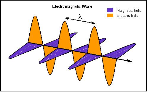
6 Electromagnetic (EM) radiation is a form of energy emitted and absorbed by charged particles, which exhibits wave-like behaviour as it travels through space.
7
8
9
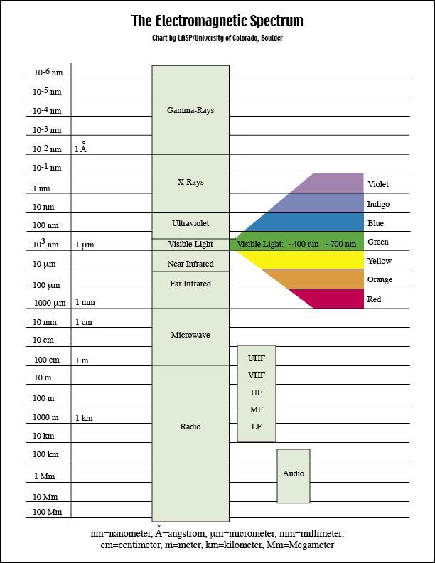
10 Defined by a wavelength or frequency The larger the wavelength the lower the frequency The smaller the wavelength the higher the frequency
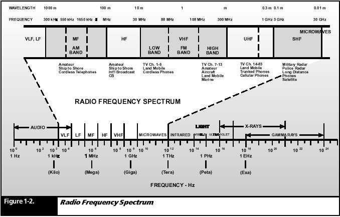
11 radio waves / spectrum 3 KHz to 300 GHz
12 Radio waves RF frequencies Frequencies falling between 3 khz and 300 GHz are called RF, since they are commonly used in radio communications. The RF range of 3 khz to 300 GHz is divided into bands of frequencies-a part of the RF spectrum. Each frequency band of the RF spectrum is ten times higher in frequency than the one immediately below it.
13
14 Spectrum tends to be divided into different categories
15 extract from Propagation of Electromagnetic Signals by Professors C. A. Levis1 and D. C. Jenn In part this complexity is due to the extra ordinary range of frequencies (or wavelengths) which are useful for signal propagation. The lowest of these are in the vicinity of 10 khz (30 km), although lower frequencies (longer wavelengths) are useful for observing geomagnetic phenomena. With the advent of lasers, the highest frequencies of interest for communicating information over considerable distances have shifted to the order of 1015 Hertz, corresponding to a wavelength of a few tenths of a micron (millionths of a meter). Thus a frequency range of eleven decades is spanned. A corresponding range in the case of structures would span from the lengths of the largest bridges to those of some viruses. A description of mechanical structures of over such a range of dimensions would also be complex.
16 HOW DO RADIO WAVES GET FROM ONE POINT TO THE OTHER?
17 antennas A radio antenna is used to radiate electromagnetic energy in the form of a radio wave. Generated radio waves are radiated into space in all directions (omnidirectional) from the transmitting antenna, at the speed of light. Another antenna receives the energy, or signal. Thus, an antenna is a conductor that either radiates or collects electromagnetic energy.
18
19 The two fundamental fields associated with every antenna are an induction field and a radiation field. The induction field is associated with the energy stored in an antenna. As an antenna radiates electromagnetic energy, a magnetic field exists around it. The induction field is considered a local field and plays no part in transmitting electromagnetic energy. The radiation field is responsible for electromagnetic radiation from the antenna. This field decreases as the distance from the antenna increases. Thus, when you are out of effective radio range, you can barely understand a transmission, or the signal is too weak to activate the receiver circuit.
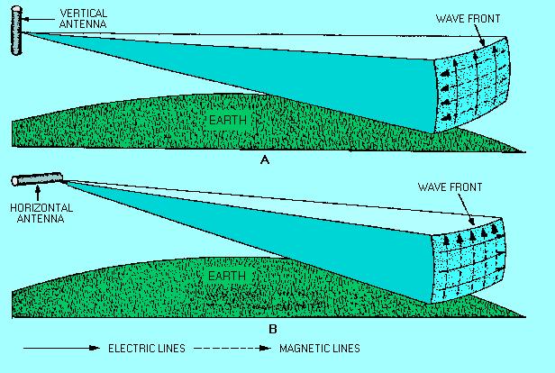
20 For a receiving antenna to pick up, or absorb the maximum amount of energy from an electromagnetic field, it must be located in the plane of polarization. This is simply a matter of orientation between the Earth and the electric field. If the lines of force in the electric field are perpendicular to the surface of the Earth, the wave is said to be vertically polarized. If the lines of fore are parallel with the Earth, the polarization is said to be horizontal
21
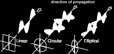
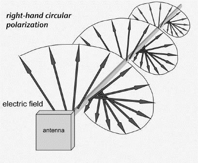
22 YOU CAN ORIENT THE ELECTROMAGNETIC WAVES?
23
24 HOW DO WE USE THE WAVES? information is placed on the wave through modulation modulation involves altering freq, amplitude or phase did you learn about this already in previous classes?
25 SO WHAT HAPPENS TO THE WAVES WHEN THEY ARE LAUNCED ON THEIR JOURNEY?
26 Different things happen to waves as they travel from point A to point B Radio waves are subject to the influence of the environment in which they are propagated. This is a very key point What things are in the environment around them???
27 Waves get transmitted Waves get absorbed Waves interact with obstacles they meet common ideas of reflection, refraction ad diffraction apply to radio waves
28 reflection A wave can be reflected from the surface of the medium it encounters If a wave is directed against a mirror, the wave that strikes the surface is called the incident wave, and the one that bounces back is called the reflected wave. This also occurs when a wave is transmitted skyward, reflect off the ionosphere, and returns to a receiving station. The angle of reflection equals the angle of incidence.
29 refraction When a wave passes from one medium into a medium that has a different propagation velocity, a change in the direction of the wave will occur. This changing of direction is called refraction. Possibly the most common recollection of this is when you dip a spoon into a glass of water; the spoon handle appears bent. Because of this a radio wave can bend as it passes through the atmosphere.
30
31 diffraction When a radio wave encounters an obstacle in its path, it bends around the obstacle. This bending is called diffraction, and results in a change of direction of part of the energy from the normal line-ofsight path.
32 diffraction here actually helps the wave get to its destination
33 scattering Occurs when the radio channel contains objects whose sizes are on the order of the wavelength or less of the propagating wave and also when the number of obstacles are quite large. They are produced by small objects, rough surfaces and other irregularities on the channel Follows same principles with diffraction Causes the transmitter energy to be radiated in many directions Lamp posts and street signs may cause scattering
34 absorption Absorption occurs when radio waves are transmitted from one medium to another, with a resultant loss of energy. For example, if a radio signal is propagated through trees during the summer months, the foliage can absorb some of the energy of the signal. The same signal transmitted during the winter months may pass because the trees have shed their leaves and do not absorb the signal. A receiving antenna should be erected so that it is in the best position possible to absorb incoming electromagnetic energy.
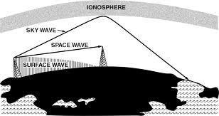
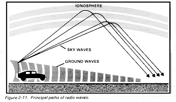
35 THERE ARE TWO BASIC MODES OF PROPAGATION - SKY WAVES GROUND WAVES
36
37
38
39 We will see that different mechanisms come in to play for the different modes of propagation
40 GROUND WAVES
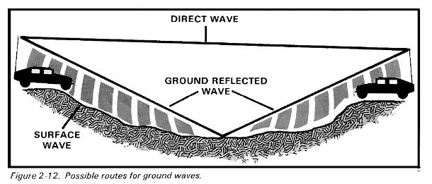
41 Ground waves Ground waves consist of three components: surface waves, direct waves, and ground-reflected waves.
42
43 The ground wave mode of propagation is very important for these frequencies
44 SURFACE WAVE Surface waves travel along the surface of the earth, reaching beyond the horizon due to the process of diffraction. Eventually, the earth absorbs surface wave energy. The frequency and conductivity of the surface over which the waves travel largely determine the effective range of surface waves. Absorption increases with frequency.
45 As a surface wave passes over the ground, it induces voltage into Earth. The induced voltage takes energy away from the surface wave, thereby weakening (attenuating) the wave as it moves away from the transmitting antenna. To reduce attenuation, the amount of induced voltage must be reduced. This is done by using vertically polarized waves, which minimize the extent to which the electric field of the wave is in contact with the Earth. When the wave is horizontally polarized, the wave's electric field is parallel with the surface of the Earth and constantly in contact with it. As a transmission is made, the signal (horizontally polarized wave) is completely attenuated within a short distance from the transmitting site. Conversely, a vertically polarized surface wave has its electric field perpendicular to the Earth and merely dips onto and off of the Earth's surface. Because of the lower signal loss, vertical polarization is vastly superior to horizontal polarization for surface wave propagation.
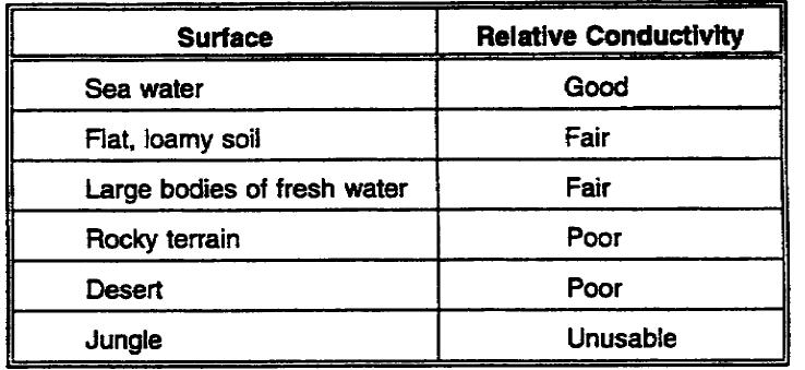
46 The amount of attenuation that a surface wave undergoes due to the induced voltage in the Earth also depends, to a considerable extent, on the electrical properties of the terrain over which the wave travels. The best type of surface is one which has good electrical conductivity. The better the conductivity, the less attenuation and the better the propagation.
47
48 Frequency is a factor in surface wave attenuation. The higher a radio wave's frequency, the shorter its wavelength will be. These high frequencies, with their shorter wavelengths, are not normally diffracted, but are absorbed by the Earth at points relatively close to the transmitting site. As a surface wave's frequency is increased, the more rapidly the surface wave will be absorbed, and attenuated, by the Earth. Because of this loss by absorption, the surface wave is impractical for long-distance transmissions with frequencies above 2 MHz. When a surface waves frequency is low enough to have a very long wavelength, the Earth appears to be very small, and diffraction is sufficient for propagation well beyond the horizon. In fact, by lowering the transmitting frequency into the VLF range and using very high-powered transmitters, the surface wave can be propagated over great distances.
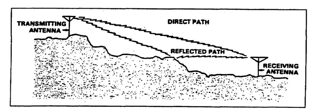
49 space waves the other part of the ground waves The space wave follows two distinct paths from transmitting antenna to receiving antenna--one through the air directly to the receiving antenna (direct wave or path), and the other reflected from the ground to the receiving antenna (ground-reflected wave or path).
50
51 The primary path of the space wave is directly from the transmitting antenna to the receiving antenna. Consequently, the receiving antenna must be located within the radio horizon of the transmitting antenna. Because space waves are refracted slightly, even when propagated through the troposphere, the radio horizon is actually about one-third farther than the line-of-sight (natural) horizon. Although space waves suffer little ground attenuation, they nevertheless are susceptible to fading. Because space waves actually follow two paths of different length (direct path and ground reflected path) to the receiving site, they may arrive in or out of phase. If these two component waves are received in phase, the result is a reinforced or stronger signal. Conversely, if they are received out of phase, they tend to cancel one another, resulting in a weak or fading signal
52 Engineering considerations for ground wave systems. There are a number of factors that affect ground wave propagation. Some of these are: 1. Frequency. Using lower frequencies results in less ground loss and increases range. 2. Antenna characteristics. Using vertical polarization, when possible, reduces the effect of the Earth "shorting out" the electric field of the wave. 3. Power. Increasing the power output result in greater distance. 4. Time of day. Sources of noise (natural and manmade) affect radio wave propagation at different times of the day. 5. Terrain. The best propagation is achieved over conductive terrain. Conductive terrain absorbs less wave energy.
53 SKY WAVES
54 Sky wave propagation is used to communicate over long distances. Sky wave propagation allows transmitted signals to be reflected (bounced) off a portion of the Earth's ionosphere and picked up at a receiver hundreds, or even thousands of miles away.
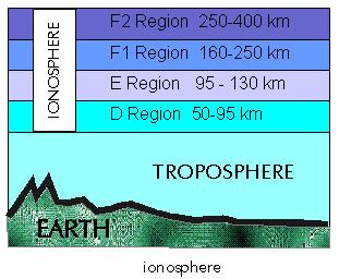
55 The Ionosphere Ionosphere. The ionosphere is the region (or layer) of the atmosphere that extends from 31 miles to about 250 miles above the Earth's surface. Its gets its name because it consists of several layers of electrically charged atoms called ions. Ions are formed by a process called ionization.
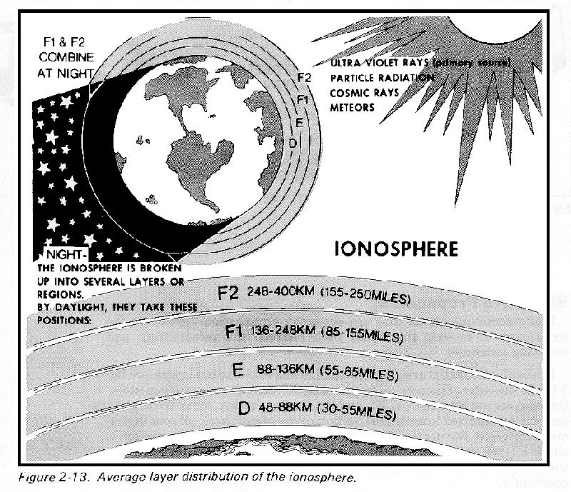
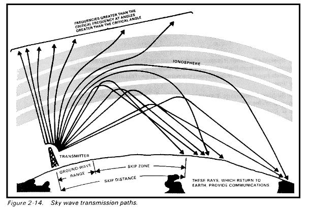
56 More details When high energy ultraviolet light waves from the sun enter the atmosphere's ionospheric region, they strike gas atoms, knocking negative electrons free. Normally, atoms are electrically neutral. When they lose an electron, atoms become positively charged and are called positive ions. This process of upsetting electrical neutrality is known as ionization. The rate at which ionization occurs depends on the density of atoms in the atmosphere and the intensity of the ultraviolet light waves, both of which vary with the activity of the sun. The ultraviolet waves striking the atmosphere are of different frequencies, causing several ionized layers to be formed at different altitudes. The density of ionized layers is partially attributed to the elevation angle of the sun, which changes constantly. Consequently, the altitude and thickness of the ionized layers vary, depending on the time of day and even the season of the year.
57 The ionosphere is composed of three regions (D, E, and F) The F region is further divided into two layers designated F1 (lower layer) and F2 (higher layer), which change with the position of the sun. The radiation in the ionosphere directly above a given point is greatest at noon, while it is least at night. When the radiation is not present, recombination sets in. The D region ranges to 55 miles above the Earth's surface. This low region of the atmosphere has low ionization. It refracts low frequency signals, but high frequencies pass through it, with some attenuation that varies with frequency and region density. The D region disappears after sunset because of recombination. The E region ranges from about 55 to 90 miles in altitude. After sunset, recombination occurs rapidly, and this region is almost gone by midnight. The E region is used during the day for HF radio transmissions ranging up to about 1500 miles. The F region ranges from about 90 to 240 miles high. During daylight hours, the F region separates into two layers-the F1 and F2 layers. At night these two layers combine. Recombination occurs slowly after sunset, so a fairly constant ionized layer is present at all times. The F layers are very useful for HF long-distance radio communications.
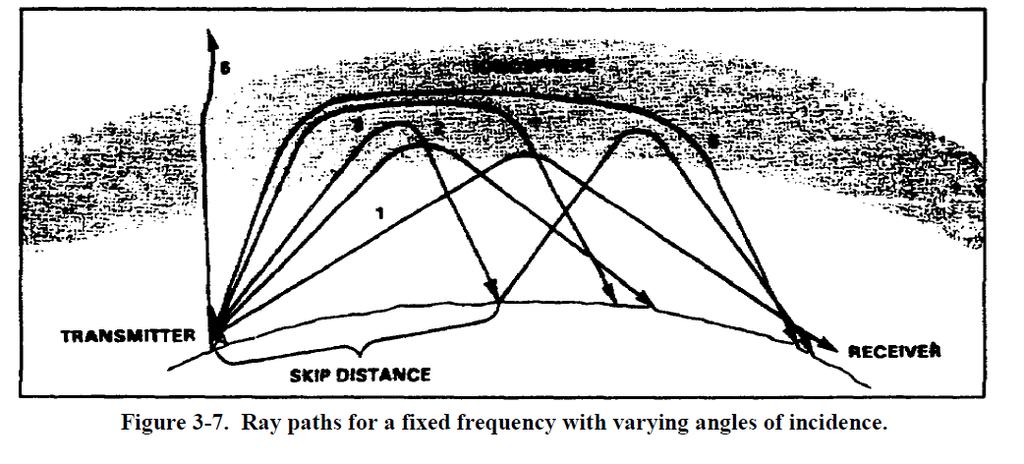
58
59
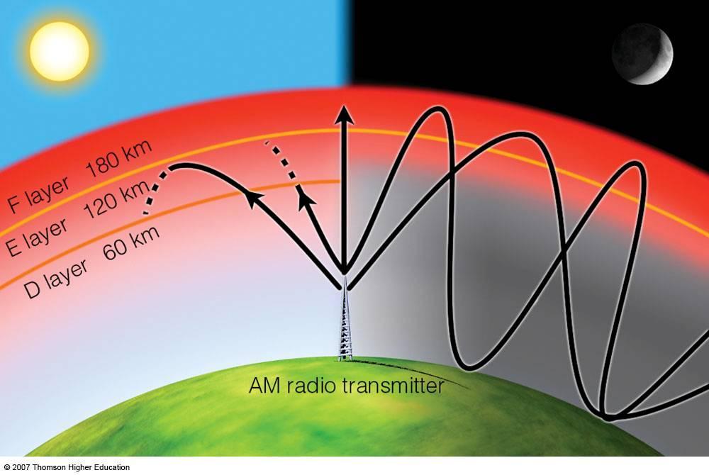
60 What happens to the radio waves The radio wave transmitted into an ionized layer is refracted (bent) as it abruptly changes velocity while entering a new medium. Each layer has a central region of relatively dense ionization which tapers off in intensity both above and below the maximum region. As a radio wave strikes a region of increased ionization, its velocity increases, causing it to bend back toward the Earth. If a radio wave strikes a thin, very highly ionized layer, the wave may be bent back and appear to have been reflected, rather than refracted back to Earth. Ionospheric reflection is more likely to occur at long wavelengths (low frequencies). This is what occurs when you bounce an AM signal off the ionosphere and it is picked up many hundreds of miles away.
61
62
63 IT IS ALL ABOUT REFRACTION For any given time, each ionospheric layer has a maximum frequency at which radio waves can be transmitted vertically and refracted back to Earth. This frequency is called the critical frequency. Radio waves transmitted at frequencies higher than the critical frequency of a given layer will pass through the layer and be lost in space. But if the wave enters into an upper layer with a higher critical frequency, the wave will be refracted back to Earth. R Radio waves of frequencies lower than the critical frequency will also be refracted back to Earth, unless they are absorbed or have been refracted from a lower layer. The lower the frequency of a radio wave, the more rapidly the wave is refracted by a given degree of ionization.
64 Notice that the 5-MHz wave is refracted quite sharply. The 20-MHz wave is refracted less sharply and returned to Earth at a greater distance. The 100-MHz wave is obviously greater than the critical frequency for that ionized layer. Therefore, it is not reacted but is lost in space.
65 It is also about angle The rate at which a wave of a given frequency is refracted by an ionized layer depends on the angle at which the wave enters the layer. The next slide shows a relevant diagram. The angle at which wave A strikes the layer is too nearly vertical for the wave to be refracted to Earth. As the wave enters the layer, it is bent slightly but passes through the layer and is lost. When the wave is reduced to an angle that is less than vertical (wave B), it strikes the layer and is refracted back to Earth. The angle made by wave B is called the critical angle for that particular frequency. Any wave that leaves the antenna at an angle greater than the critical angle will penetrate the ionospheric layer for that frequency and will be lost in space. Wave C strikes the ionosphere at the smallest angle that can be refracted and still return to Earth. At any smaller angle, the wave will be refracted but will not return to Earth.
66 The thee different waves WAVE A WAVE B WAVE C They are all launched at different angles. The angle has an impact.
67 The 2-MHz wave strikes the layer at the critical angle for that frequency and is refracted back to Earth. Although the 5-MHz wave (broken line) strikes the ionosphere at a lesser angle, it nevertheless penetrates the layer and is lost. As the angle is lowered from the vertical, however, a critical angle for the 5-MHz wave is reached, and the wave is then refracted to Earth
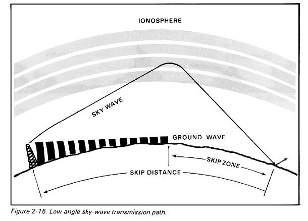
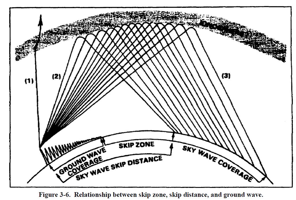
68 The skip distance is the distance from the transmitter to the point where the sky wave is first returned to Earth. The skip distance's size depends on the wave's frequency, the angle of incidence, and the degree of ionization present. Obviously, the skip distance will change through the day as the level of ionization changes. The skip zone is a zone of silence between the point where the ground wave becomes too weak for reception and the point where the sky wave is first returned to Earth. The skip zone's size depends on the extent of ground wave coverage and the skip distance. When the ground wave coverage is great enough or the skip distance is short enough that no zone of silence occurs, there is no skip zone. Occasionally, the first sky wave will return to Earth within range of the ground wave. If the sky and ground waves are nearly of equal intensity, the sky wave alternately reinforces and cancels the ground wave, causing severe fading. This is caused by the phase difference between the two waves, which is a result of the longer path travelled by the sky wave.
69
70
71
72
73
74 Obstacles to sky wave propagation Absorption of RF energy in the ionosphere result in loss of signal strength and reduced transmission distances. Most ionospheric absorption occurs in the lower regions of the atmosphere where ionization density is greatest. As a radio wave passes into the ionosphere, it loses energy to the free electrons and ions. The highly dense D and E layers provide the greatest absorption of radio waves. A radio signal will at times have variations in its strength. This is called fading. A radio wave refracted by the ionosphere or reflected from the Earth's surface may suffer changes in its polarization. This change in polarization results in weak signal reception. Fading is also caused by absorption of the RF energy in the ionosphere.
75 There are other losses which affect the ionospheric propagation of radio waves, besides energy losses in the atmosphere. These are ground-reflection loss and free space loss. Ground-reflection loss occurs when a transmitted signal is refracted off the ionosphere, strikes the Earth, and is reflected back to the ionosphere. RF energy is lost each time the radio wave is reflected from the surface. The amount of energy lost depends on the frequency of the wave, the angle of incidence, ground irregularities, and the electrical conductivity of the point of reflection. Free space loss occurs when a travelling radio wave spreads out, much like a flashlight's beam. As distance increases, the amount of energy contained in a wavefront will decrease. By the time the energy is received at the antenna, the wavefront is so spread out that the antenna extends into only a very small fraction of the wavefront.
76 Electromagnetic interference (EMI) can significantly reduce the quality of communications. This is because the radio receiver is picking up both the desired transmission and electromagnetic radiation from an undesired source. Sources of EMI are manmade and natural. Examples of manmade EMI include assorted radio transmitters that can cause mutual interference, and various electrical devices that generate interfering signals, including ignition systems, generators, motors, and so forth. This is the reason you must never transmit a radio signal across a signal site, or position your communications systems near power lines. You can appreciate the severity of this type of interference the next time you listen to your car radio while driving under electrical power lines. The intensity of the radiation from the power lines overwhelms the signal (music) you have tuned in, resulting in a brief intolerable condition. Many sources of manmade interference may cause intense disruption of communication during the day and drop off at night when they are not in use. Natural interference is generated by phenomena such as thunderstorms, cosmic sources, and the sun. This causes static that you often hear when listening to a radio. Natural interference is disruptive, particularly in the HF band. Listening to your car radio on the AM band during a thunderstorm will reveal the impact of this interference; the intensity of the radiated energy from the lightning discharges interferes with the signal you have tuned in. At night, there are increases in the noise levels. This is attributed to both manmade and natural interferences. Because of the change at night in the layers of the F region, many spurious signals can be tuned in. Because of an increase in the number of signals reflected off of the ionosphere, more than one station may be heard simultaneously, causing interference. Some stations change their poweroutput. This can also affect the noise levels.
77 Classification Band Initials Frequency Range Characteristics Extremely low ELF < 300 Hz Infra low ILF 300 Hz - 3 khz Ground wave Very low VLF 3 khz - 30 khz Low LF 30 khz khz Medium MF 300 khz - 3 MHz Ground/Sky wave High HF 3 MHz - 30 MHz Sky wave Very high VHF 30 MHz MHz Ultra high UHF 300 MHz - 3 GHz Super high SHF 3 GHz - 30 GHz Space wave Extremely high EHF 30 GHz GHz Tremendously high THF 300 GHz GHz
78 NASA video
Reading 28 PROPAGATION THE IONOSPHERE
 Reading 28 Ron Bertrand VK2DQ http://www.radioelectronicschool.com PROPAGATION THE IONOSPHERE The ionosphere is a region of the upper atmosphere extending from a height of about 60 km to greater than 500
Polarization orientation of the electric field vector with respect to the earth s surface (ground).
.") Free space propagation of electromagnetic waves is often called radio-frequency (rf) propagation or simply radio propagation. The earth s atmosphere, as medium introduces losses and impairments to the
Free space propagation of electromagnetic waves is often called radio-frequency (rf) propagation or simply radio propagation. The earth s atmosphere, as medium introduces losses and impairments to the
RADIO WAVE PROPAGATION
 CHAPTER 2 RADIO WAVE PROPAGATION Radio direction finding (RDF) deals with the direction of arrival of radio waves. Therefore, it is necessary to understand the basic principles involved in the propagation
Lesson 12: Signal Propagation
 Lesson 12: Signal Propagation Preparation for Amateur Radio Technician Class Exam Topics HF Propagation Ground-wave Sky-wave Ionospheric regions VHF/UHF Propagation Line-of-sight Tropospheric Bending and
3C5 Telecommunications. what do radios look like? mobile phones. Linda Doyle CTVR The Telecommunications Research Centre
 3C5 Telecommunications what do radios look like? Linda Doyle CTVR The Telecommunications Research Centre ledoyle@tcd.ie Oriel/Dunlop House 2009 mobile phones talk is cheap.. bluetooth 3G WLAN/802.11 GSM
Chapter 6 Propagation
 Chapter 6 Propagation Al Penney VO1NO Objectives To become familiar with: Classification of waves wrt propagation; Factors that affect radio wave propagation; and Propagation characteristics of Amateur
PROPAGATION MODELING 4C4
 PROPAGATION MODELING ledoyle@tcd.ie 4C4 http://ledoyle.wordpress.com/temp/ Classification Band Initials Frequency Range Characteristics Extremely low ELF < 300 Hz Infra low ILF 300 Hz - 3 khz Ground wave
Data and Computer Communications Chapter 4 Transmission Media
 Data and Computer Communications Chapter 4 Transmission Media Ninth Edition by William Stallings Data and Computer Communications, Ninth Edition by William Stallings, (c) Pearson Education - Prentice Hall,
4/18/2012. Supplement T3. 3 Exam Questions, 3 Groups. Amateur Radio Technician Class
 Amateur Radio Technician Class Element 2 Course Presentation ti ELEMENT 2 SUB-ELEMENTS Technician Licensing Class Supplement T3 Radio Wave Characteristics 3 Exam Questions, 3 Groups T1 - FCC Rules, descriptions
Antenna & Propagation. Basic Radio Wave Propagation
 For updated version, please click on http://ocw.ump.edu.my Antenna & Propagation Basic Radio Wave Propagation by Nor Hadzfizah Binti Mohd Radi Faculty of Electric & Electronics Engineering hadzfizah@ump.edu.my
Technician License Course Chapter 4
 Technician License Course Chapter 4 Propagation, Basic Antennas, Feed lines & SWR K0NK 26 Jan 18 The Antenna System Antenna: Facilitates the sending of your signal to some distant station. Feed line: Connects
Chapter 15: Radio-Wave Propagation
 Chapter 15: Radio-Wave Propagation MULTIPLE CHOICE 1. Radio waves were first predicted mathematically by: a. Armstrong c. Maxwell b. Hertz d. Marconi 2. Radio waves were first demonstrated experimentally
14. COMMUNICATION SYSTEM
 14. COMMUNICATION SYSTEM SYNOPSIS : INTRODUCTION 1. The exchange of information between a sender and receiver is called communication. 2. The arrangement of devices to transfere the information is called
OBJECTIVES: PROPAGATION INTRO RADIO WAVES POLARIZATION LINE OF SIGHT, GROUND WAVE, SKY WAVE IONOSPHERE REGIONS PROPAGATION, HOPS, SKIPS ZONES THE
 WAVE PROPAGATION OBJECTIVES: PROPAGATION INTRO RADIO WAVES POLARIZATION LINE OF SIGHT, GROUND WAVE, SKY WAVE IONOSPHERE REGIONS PROPAGATION, HOPS, SKIPS ZONES THE IONOSPHERIC LAYERS ABSORPTION AND FADING
Chapter 1 Introduction
 Wireless Information Transmission System Lab. Chapter 1 Introduction National Sun Yat-sen University Table of Contents Elements of a Digital Communication System Communication Channels and Their Wire-line
4/29/2012. General Class Element 3 Course Presentation. Radio Wave Propagation. Radio Wave Propagation. Radio Wave Propagation.
 General Class Element 3 Course Presentation ti ELEMENT 3 SUB ELEMENTS General Licensing Class Subelement G3 3 Exam Questions, 3 Groups G1 Commission s Rules G2 Operating Procedures G3 G4 Amateur Radio
Chapter 1: Telecommunication Fundamentals
 Chapter 1: Telecommunication Fundamentals Block Diagram of a communication system Noise n(t) m(t) Information (base-band signal) Signal Processing Carrier Circuits s(t) Transmission Medium r(t) Signal
Chapter 3. Mobile Radio Propagation
 Chapter 3 Mobile Radio Propagation Based on the slides of Dr. Dharma P. Agrawal, University of Cincinnati and Dr. Andrea Goldsmith, Stanford University Propagation Mechanisms Outline Radio Propagation
Sw earth Dw Direct wave GRw Ground reflected wave Sw Surface wave
 WAVE PROPAGATION By Marcel H. De Canck, ON5AU Electromagnetic radio waves can propagate in three different ways between the transmitter and the receiver. 1- Ground waves 2- Troposphere waves 3- Sky waves
Chapter 7 HF Propagation. Ionosphere Solar Effects Scatter and NVIS
 Chapter 7 HF Propagation Ionosphere Solar Effects Scatter and NVIS Ionosphere and Layers Radio Waves Bent by the Ionosphere Daily variation of Ionosphere Layers Ionospheric Reflection Conduction by electrons
Chapter 13: Wave Propagation. EET-223: RF Communication Circuits Walter Lara
 Chapter 13: Wave Propagation EET-223: RF Communication Circuits Walter Lara Electrical to Electromagnetic Conversion Since the atmosphere is not a conductor of electrons (instead a good insulator), electrical
Topics in Propagation
 Topics in Propagation Extra Class Course Spring 2013 Andy Durbin k3wyc Propagation The magic that allows a signal to travel between the transmitting antenna and the receiving antenna. This course is limited
Wireless Transmission Rab Nawaz Jadoon
 Wireless Transmission Rab Nawaz Jadoon DCS Assistant Professor COMSATS IIT, Abbottabad Pakistan COMSATS Institute of Information Technology Mobile Communication Frequency Spectrum Note: The figure shows
Amateur Radio License. Propagation and Antennas
 Amateur Radio License Propagation and Antennas Todays Topics Propagation Antennas Propagation Modes Ground wave Low HF and below, ground acts as waveguide Line-of-Sight (LOS) VHF and above, radio waves
FCC Technician License Course
 FCC Technician License Course 2014-2018 FCC Element 2 Technician Class Question Pool Presented by: Tamiami Amateur Radio Club (TARC) WELCOME To the third of 4, 3-hour classes presented by TARC to prepare
Radio Propagation Fundamentals
 Radio Propagation Fundamentals Concept of Electromagnetic Wave Propagation Mechanisms Modes of Propagation Propagation Models Path Profiles Link Budget Fading Channels Electromagnetic (EM) Waves EM Wave
Computer Networks Lecture -4- Transmission Media. Dr. Methaq Talib
 Computer Networks Lecture -4- Transmission Media Dr. Methaq Talib Transmission Media A transmission medium can be broadly defined as anything that can carry information from a source to a destination.
Section 1 Wireless Transmission
 Part : Wireless Communication! section : Wireless Transmission! Section : Digital modulation! Section : Multiplexing/Medium Access Control (MAC) Section Wireless Transmission Intro. to Wireless Transmission
Figure 4-1. Figure 4-2 Classes of Transmission Media
 Electromagnetic Spectrum Chapter 4 Transmission Media Computers and other telecommunication devices transmit signals in the form of electromagnetic energy, which can be in the form of electrical current,
Radio Communication. Presentation created by: András Balogh
 Radio Communication Presentation created by: András Balogh AM and FM The goal is to transmit a modulating signal S(t) via a wave sin(ωt). In case of AM, the product of the modulation is f(t)=(a+s(t))*sin(ωt);
Session2 Antennas and Propagation
 Wireless Communication Presented by Dr. Mahmoud Daneshvar Session2 Antennas and Propagation 1. Introduction Types of Anttenas Free space Propagation 2. Propagation modes 3. Transmission Problems 4. Fading
UNIT Derive the fundamental equation for free space propagation?
 UNIT 8 1. Derive the fundamental equation for free space propagation? Fundamental Equation for Free Space Propagation Consider the transmitter power (P t ) radiated uniformly in all the directions (isotropic),
Electromagnetic (Light) Waves Electromagnetic Waves
 Waves Electromagnetic Waves") Physics R Date: Review Questions 1. An ocean wave traveling at 3 m/s has a wavelength of 1.6 meters. a. What is the frequency of the wave? b. What is the period of the wave? Electromagnetic (Light) Waves
Physics R Date: Review Questions 1. An ocean wave traveling at 3 m/s has a wavelength of 1.6 meters. a. What is the frequency of the wave? b. What is the period of the wave? Electromagnetic (Light) Waves
Antennas and Propagation Chapters T4, G7, G8 Antenna Fundamentals, More Antenna Types, Feed lines and Measurements, Propagation
 Antennas and Propagation Chapters T4, G7, G8 Antenna Fundamentals, More Antenna Types, Feed lines and Measurements, Propagation =============================================================== Antenna Fundamentals
Electronics Technician
 NONRESIDENT TRAINING COURSE Electronics Technician Volume 7 Antennas and Wave Propagation NAVEDTRA 14092 Notice: NETPDTC is no longer responsible for the content accuracy of the NRTCs. For content issues,
Electronics Technician
 NAVEDTRA 12417 Naval Education and October 1995 Training Manual Training Command 0502-LP-480-2900 (TRAMAN) Electronics Technician Volume 7 Antennas and Wave Propagation DISTRIBUTION STATEMENT A: Approved
Plasma in the ionosphere Ionization and Recombination
 Plasma in the ionosphere Ionization and Recombination Jamil Muhammad Supervisor: Professor kjell Rönnmark 1 Contents: 1. Introduction 3 1.1 History.3 1.2 What is the ionosphere?...4 2. Ionization and recombination.5
William Stallings Data and Computer Communications 7 th Edition. Chapter 4 Transmission Media
 William Stallings Data and Computer Communications 7 th Edition Chapter 4 Transmission Media Overview Guided - wire Unguided - wireless Characteristics and quality determined by medium and signal For guided,
Antennas and Propagation
 CMPE 477 Wireless and Mobile Networks Lecture 3: Antennas and Propagation Antennas Propagation Modes Line of Sight Transmission Fading in the Mobile Environment Introduction An antenna is an electrical
# DEFINITIONS TERMS. 2) Electrical energy that has escaped into free space. Electromagnetic wave
 Electrical energy that has escaped into free space. Electromagnetic wave") CHAPTER 14 ELECTROMAGNETIC WAVE PROPAGATION # DEFINITIONS TERMS 1) Propagation of electromagnetic waves often called radio-frequency (RF) propagation or simply radio propagation. Free-space 2) Electrical
CHAPTER 14 ELECTROMAGNETIC WAVE PROPAGATION # DEFINITIONS TERMS 1) Propagation of electromagnetic waves often called radio-frequency (RF) propagation or simply radio propagation. Free-space 2) Electrical
Antennas and Propagation
 Mobile Networks Module D-1 Antennas and Propagation 1. Introduction 2. Propagation modes 3. Line-of-sight transmission 4. Fading Slides adapted from Stallings, Wireless Communications & Networks, Second
Maximum Usable Frequency
 Maximum Usable Frequency 15 Frequency (MHz) 10 5 0 Maximum Usable Frequency Usable Frequency Window Lowest Usable Frequency Solar Flare 6 12 18 24 Time (Hours) Radio Blackout Usable Frequency Window Ken
Antennas and Propagation. Prelude to Chapter 4 Propagation
 Antennas and Propagation Prelude to Chapter 4 Propagation Introduction An antenna is an electrical conductor or system of conductors for: Transmission - radiates electromagnetic energy into space (involves
Antennas and Propagation
 Antennas and Propagation Chapter 5 Introduction An antenna is an electrical conductor or system of conductors Transmission - radiates electromagnetic energy into space Reception - collects electromagnetic
Antennas and Propagation. Chapter 5
 Antennas and Propagation Chapter 5 Introduction An antenna is an electrical conductor or system of conductors Transmission - radiates electromagnetic energy into space Reception - collects electromagnetic
Antennas and Propagation. Chapter 5
 Antennas and Propagation Chapter 5 Introduction An antenna is an electrical conductor or system of conductors Transmission - radiates electromagnetic energy into space Reception - collects electromagnetic
Chapter 16 Light Waves and Color
 Chapter 16 Light Waves and Color Lecture PowerPoint Copyright The McGraw-Hill Companies, Inc. Permission required for reproduction or display. What causes color? What causes reflection? What causes color?
WIRELESS TRANSMISSION
 COMP 635: WIRELESS NETWORKS WIRELESS TRANSMISSION Jasleen Kaur Fall 205 Outline Frequenc Spectrum Ø Usage and Licensing Signals and Antennas Ø Propagation Characteristics Multipleing Ø Space, Frequenc,
Electronics Technician
 NONRESIDENT TRAINING COURSE Electronics Technician Volume 7 Antennas and Wave Propagation NAVEDTRA 14092 DISTRIBUTION STATEMENT A: Approved for public release; distribution is unlimited. Sailor s Creed
RF Propagation. By Tim Kuhlman, PE KD7RUS
 RF Propagation By Tim Kuhlman, PE KD7RUS Purpose of this Seminar In this seminar we will attempt to answer the following questions: What is RF propagation? What are the different types of propagation?
Data and Computer Communications. Tenth Edition by William Stallings
 Data and Computer Communications Tenth Edition by William Stallings Data and Computer Communications, Tenth Edition by William Stallings, (c) Pearson Education - Prentice Hall, 2013 Wireless Transmission
UNDER STANDING RADIO FREQUENCY Badger Meter, Inc.
 UNDER STANDING RADIO FREQUENCY UNDERSTANDING RADIO FREQUENCY Regional Sales Meeting March 1-2, 2011 Brian Fiut Sr. Product Manager Itron Inc. Liberty Lake, WA August 25, 2010 RADIO PROPAGATION Radio consists
Unguided Transmission Media
 CS311 Data Communication Unguided Transmission Media by Dr. Manas Khatua Assistant Professor Dept. of CSE IIT Jodhpur E-mail: manaskhatua@iitj.ac.in Web: http://home.iitj.ac.in/~manaskhatua http://manaskhatua.github.io/
If maximum electron density in a layer is less than n', the wave will penetrate the layer
 UNIT-7 1. Briefly the describe the terms related to the sky wave propagation: virtual heights, critical frequency, maximum usable frequency, skip distance and fading? Ans: Sky wave propagation: It is also
Electromagnetic Waves
 Electromagnetic Waves What is an Electromagnetic Wave? An EM Wave is a disturbance that transfers energy through a field. A field is a area around an object where the object can apply a force on another
Definitions of Technical Terms
 Definitions of Technical Terms Terms Ammeter Amperes, Amps Band Capacitor Carrier Squelch Diode Dipole Definitions How is an ammeter usually connected = In series with the circuit What instrument is used
RF Propagation. By Tim Kuhlman, PE KD7RUS
 RF Propagation By Tim Kuhlman, PE KD7RUS Purpose of this Seminar In this seminar we will attempt to answer the following questions: What is RF propagation? What are the different types of propagation?
Get Discount Coupons for your Coaching institute and FREE Study Material at COMMUNICATION SYSTEMS
 COMMUNICATION SYSTEMS 1. BASICS OF COMMUNICATION 2. AMPLITUDE MODULATION Get Discount Coupons for your Coaching institute and FREE Study Material at www.pickmycoaching.com 1 BASICS OF COMMUNICATION 1.
Maximum date rate=2hlog 2 V bits/sec. Maximum number of bits/sec=hlog 2 (1+S/N)
") Basics Data can be analog or digital. The term analog data refers to information that is continuous, digital data refers to information that has discrete states. Analog data take on continuous values.
Basics Data can be analog or digital. The term analog data refers to information that is continuous, digital data refers to information that has discrete states. Analog data take on continuous values.
High Frequency Propagation (and a little about NVIS)
") High Frequency Propagation (and a little about NVIS) Tom McDermott, N5EG August 18, 2010 September 2, 2010 Updated: February 7, 2013 The problem Radio waves, like light waves, travel in ~straight lines.
High Frequency Propagation (and a little about NVIS) Tom McDermott, N5EG August 18, 2010 September 2, 2010 Updated: February 7, 2013 The problem Radio waves, like light waves, travel in ~straight lines.
Radiation and Particles from the. Sun
 2017 Radiation and Particles from the Photons Sun Photons (300000km/s ~ 8m 20s) radio waves, infra red, visible light, ultra violet, x-ray, x galactic waves, Solar Flux (30000km/s ~ 8m 20s) The 10.7 cm
Antennas & Propagation. CSG 250 Fall 2007 Rajmohan Rajaraman
 Antennas & Propagation CSG 250 Fall 2007 Rajmohan Rajaraman Introduction An antenna is an electrical conductor or system of conductors o Transmission - radiates electromagnetic energy into space o Reception
CHAPTER 2 WIRELESS CHANNEL
 CHAPTER 2 WIRELESS CHANNEL 2.1 INTRODUCTION In mobile radio channel there is certain fundamental limitation on the performance of wireless communication system. There are many obstructions between transmitter
Project = An Adventure : Wireless Networks. Lecture 4: More Physical Layer. What is an Antenna? Outline. Page 1
 Project = An Adventure 18-759: Wireless Networks Checkpoint 2 Checkpoint 1 Lecture 4: More Physical Layer You are here Done! Peter Steenkiste Departments of Computer Science and Electrical and Computer
Channel Modeling and Characteristics
 Channel Modeling and Characteristics Dr. Farid Farahmand Updated:10/15/13, 10/20/14 Line-of-Sight Transmission (LOS) Impairments The received signal is different from the transmitted signal due to transmission
Introduction to HF Propagation. Rick Fletcher, W7YP FVARC November 20, 2018
 Introduction to HF Propagation Rick Fletcher, W7YP FVARC November 20, 2018 Topics The HF Bands How HF propagation works Overview by HF band Sources of solar and propagation information Working HF during
Technician License Course Chapter 2 Radio and Signals Fundamentals
 Technician License Course Chapter 2 Radio and Signals Fundamentals Handling Large and Small Numbers Electronics and Radio use a large range of sizes, i.e., 0.000000000001 to 1000000000000. Scientific Notation
Class Overview. Antenna Fundamentals Repeaters Duplex and Simplex Nets and Frequencies Cool Radio Functions Review
 Class Overview Antenna Fundamentals Repeaters Duplex and Simplex Nets and Frequencies Cool Radio Functions Review Antennas Antennas An antenna is a device used for converting electrical currents into electromagnetic
COPYRIGHTED MATERIAL INTRODUCTION 1.1 DEFINITION OF PROPAGATION
 1 INTRODUCTION 1.1 DEFINITION OF PROPAGATION Information can be transmitted in many ways. The use of electromagnetic waves for this purpose is attractive, in part, because direct physical connections such
1. Terrestrial propagation
 Rec. ITU-R P.844-1 1 RECOMMENDATION ITU-R P.844-1 * IONOSPHERIC FACTORS AFFECTING FREQUENCY SHARING IN THE VHF AND UHF BANDS (30 MHz-3 GHz) (Question ITU-R 218/3) (1992-1994) Rec. ITU-R PI.844-1 The ITU
E-716-A Mobile Communications Systems. Lecture #2 Basic Concepts of Wireless Transmission (p1) Instructor: Dr. Ahmad El-Banna
 Instructor: Dr. Ahmad El-Banna") October 2014 Ahmad El-Banna Integrated Technical Education Cluster At AlAmeeria E-716-A Mobile Communications Systems Lecture #2 Basic Concepts of Wireless Transmission (p1) Instructor: Dr. Ahmad El-Banna
October 2014 Ahmad El-Banna Integrated Technical Education Cluster At AlAmeeria E-716-A Mobile Communications Systems Lecture #2 Basic Concepts of Wireless Transmission (p1) Instructor: Dr. Ahmad El-Banna
Technician License Course Chapter 4. Lesson Plan Module 9 Antenna Fundamentals, Feed Lines & SWR
 Technician License Course Chapter 4 Lesson Plan Module 9 Antenna Fundamentals, Feed Lines & SWR The Antenna System Antenna: Transforms current into radio waves (transmit) and vice versa (receive). Feed
THE IONOSPHERE AND RADIO PROPAGATION
 INTERNATIONAL JOURNAL OF ELECTRONICS AND COMMUNICATION ENGINEERING & TECHNOLOGY (IJECET) International Journal of Electronics and Communication Engineering & Technology (IJECET), ISSN 0976 ISSN 0976 6464(Print)
(A) 2f (B) 2 f (C) f ( D) 2 (E) 2
 2f (B) 2 f (C) f ( D) 2 (E) 2") 1. A small vibrating object S moves across the surface of a ripple tank producing the wave fronts shown above. The wave fronts move with speed v. The object is traveling in what direction and with what
1. A small vibrating object S moves across the surface of a ripple tank producing the wave fronts shown above. The wave fronts move with speed v. The object is traveling in what direction and with what
COMMUNICATION SYSTEMS -I
 COMMUNICATION SYSTEMS -I Communication : It is the act of transmission of information. ELEMENTS OF A COMMUNICATION SYSTEM TRANSMITTER MEDIUM/CHANNEL: The physical medium that connects transmitter to receiver
Space Weather and Propagation JANUARY 14, 2017
 Space Weather and Propagation MARTIN BUEHRING -KB4MG ELEC T R ICAL ENGINEER, A M AT EUR EXTRA CLASS LICENSE HOLDER JANUARY 14, 2017 Why know about Space Weather? Our SUN has an enormous affect not only
RECOMMENDATION ITU-R P Prediction of sky-wave field strength at frequencies between about 150 and khz
 Rec. ITU-R P.1147-2 1 RECOMMENDATION ITU-R P.1147-2 Prediction of sky-wave field strength at frequencies between about 150 and 1 700 khz (Question ITU-R 225/3) (1995-1999-2003) The ITU Radiocommunication
CHAPTER -15. Communication Systems
 CHAPTER -15 Communication Systems COMMUNICATION Communication is the act of transmission and reception of information. COMMUNICATION SYSTEM: A system comprises of transmitter, communication channel and
Liquidmetal Electromagnetic Properties & RF Shielding Overview
 Liquidmetal Electromagnetic Properties & RF Shielding Overview Liquidmetal alloy is more transparent to RF signals than many similar materials 1 Introduction H ow a material interacts with radio frequency
PRINCIPLES OF COMMUNICATION SYSTEMS. Lecture 1- Introduction Elements, Modulation, Demodulation, Frequency Spectrum
 PRINCIPLES OF COMMUNICATION SYSTEMS Lecture 1- Introduction Elements, Modulation, Demodulation, Frequency Spectrum Topic covered Introduction to subject Elements of Communication system Modulation General
COMMUNICATION SYSTEMS MARKS WEIGHTAGE 5 marks
 COMMUNICATION SYSTEMS MARKS WEIGHTAGE 5 marks QUICK REVISION (Important Concepts & Formulas) Communication is the act of transmission of information. In electronics, the term communication refers to sending,
VI. Signal Propagation Effects. Image courtesy of
 VI. Signal Propagation Effects Image courtesy of www.tpub.com 56 VI. Signal Propagation Effects Name Date Class At Home Assignment Tune to the most remote AM station you can find. You should attempt to
Ionospheric Propagation
 Ionospheric Propagation Page 1 Ionospheric Propagation The ionosphere exists between about 90 and 1000 km above the earth s surface. Radiation from the sun ionizes atoms and molecules here, liberating
Technician License Course Chapter 2 Radio and Electronics Fundamentals. PHYS 401 Spring 2009 P. Reiff, Rice University
 Technician License Course Chapter 2 Radio and Electronics Fundamentals PHYS 401 Spring 2009 P. Reiff, Rice University Basic Station Organization Station Equipment Receiver Transmitter Antenna Power Supply
The Knowledge Bank at The Ohio State University. Ohio State Engineer
 The Knowledge Bank at The Ohio State University Ohio State Engineer Title: Creators: The Ionosphere and Its Effect on the Propagation of Radio Waves Weisz, Henry Issue Date: 1944-11 Publisher: Ohio State
ELECTROMAGNETIC SPECTRUM ELECTROMAGNETIC SPECTRUM
 LECTURE:2 ELECTROMAGNETIC SPECTRUM ELECTROMAGNETIC SPECTRUM Electromagnetic waves: In an electromagnetic wave the electric and magnetic fields are mutually perpendicular. They are also both perpendicular
Vehicle Networks. Wireless communication basics. Univ.-Prof. Dr. Thomas Strang, Dipl.-Inform. Matthias Röckl
 Vehicle Networks Wireless communication basics Univ.-Prof. Dr. Thomas Strang, Dipl.-Inform. Matthias Röckl Outline Wireless Signal Propagation Electro-magnetic waves Signal impairments Attenuation Distortion
Interpretation and Classification of P-Series Recommendations in ITU-R
 Int. J. Communications, Network and System Sciences, 2016, 9, 117-125 Published Online May 2016 in SciRes. http://www.scirp.org/journal/ijcns http://dx.doi.org/10.4236/ijcns.2016.95010 Interpretation and
Technician License. Course
 Technician License Course Technician License Course Chapter 4 Lesson Plan Module - 9 Antenna Fundamentals Feed Lines & SWR The Antenna System The Antenna System Antenna: Transforms current into radio waves
"Natural" Antennas. Mr. Robert Marcus, PE, NCE Dr. Bruce C. Gabrielson, NCE. Security Engineering Services, Inc. PO Box 550 Chesapeake Beach, MD 20732
 Published and presented: AFCEA TEMPEST Training Course, Burke, VA, 1992 Introduction "Natural" Antennas Mr. Robert Marcus, PE, NCE Dr. Bruce C. Gabrielson, NCE Security Engineering Services, Inc. PO Box
Mobile and Wireless Networks Course Instructor: Dr. Safdar Ali
 Mobile and Wireless Networks Course Instructor: Dr. Safdar Ali BOOKS Text Book: William Stallings, Wireless Communications and Networks, Pearson Hall, 2002. BOOKS Reference Books: Sumit Kasera, Nishit
Unguided Media and Matched Filter After this lecture, you will be able to Example?
 Unguided Media and Matched Filter After this lecture, you will be able to describe the physical and transmission characteristics of various unguided media Example? B.1 Unguided media Guided to unguided
Global Maps with Contoured Ionosphere Properties Some F-Layer Anomalies Revealed By Marcel H. De Canck, ON5AU. E Layer Critical Frequencies Maps
 Global Maps with Contoured Ionosphere Properties Some F-Layer Anomalies Revealed By Marcel H. De Canck, ON5AU In this column, I shall handle some possibilities given by PROPLAB-PRO to have information
CHAPTER 21 RADIO WAVES
 CHAPTER 21 RADIO WAVES ELECTROMAGNETIC WAVE PROPAGATION 2100. Source of Radio Waves Consider electric current as a flow of electrons through a conductor between points of differing potential/voltage/electric
Ionospheric Impacts on UHF Space Surveillance. James C. Jones Darvy Ceron-Gomez Dr. Gregory P. Richards Northrop Grumman
 Ionospheric Impacts on UHF Space Surveillance James C. Jones Darvy Ceron-Gomez Dr. Gregory P. Richards Northrop Grumman CONFERENCE PAPER Earth s atmosphere contains regions of ionized plasma caused by
6 Radio and RF. 6.1 Introduction. Wavelength (m) Frequency (Hz) Unit 6: RF and Antennas 1. Radio waves. X-rays. Microwaves. Light
 Frequency (Hz) Unit 6: RF and Antennas 1. Radio waves. X-rays. Microwaves. Light") 6 Radio and RF Ref: http://www.asecuritysite.com/wireless/wireless06 6.1 Introduction The electromagnetic (EM) spectrum contains a wide range of electromagnetic waves, from radio waves up to X-rays (as
6 Radio and RF Ref: http://www.asecuritysite.com/wireless/wireless06 6.1 Introduction The electromagnetic (EM) spectrum contains a wide range of electromagnetic waves, from radio waves up to X-rays (as
Structure of the Lecture
 Structure of the Lecture Chapter 2 Technical Basics: Layer 1 Methods for Medium Access: Layer 2 Representation of digital signals on an analogous medium Signal propagation Characteristics of antennas Chapter
ANTENNA THEORY WAVE PROPAGATION HF ANTENNAS
 ANTENNA THEORY WAVE PROPAGATION & HF ANTENNAS FREQUENCY SPECTRUM INFORMATION Frequency range American designator below 300 Hz..ELF (extremely Low Frequency) 300-3000 Hz..ILF (Intermediate Low Frequency)
SODAR- sonic detecting and ranging
 Active Remote Sensing of the PBL Immersed vs. remote sensors Active vs. passive sensors RADAR- radio detection and ranging WSR-88D TDWR wind profiler SODAR- sonic detecting and ranging minisodar RASS RADAR
UNIT- 7. Frequencies above 30Mhz tend to travel in straight lines they are limited in their propagation by the curvature of the earth.
 UNIT- 7 Radio wave propagation and propagation models EM waves below 2Mhz tend to travel as ground waves, These wave tend to follow the curvature of the earth and lose strength rapidly as they travel away