Nick Garner N3WG and George Zafiropoulos KJ6VU
|
|
|
- Lynne Lee
- 5 years ago
- Views:
Transcription

1 Nick Garner N3WG and George Zafiropoulos KJ6VU
2 Introduction Over the last few years, there has been a significant increase in the number of radio amateurs interested in portable operating. This is due to multiple factors including the availability of high quality portable radio equipment, limitations to putting up large HF antennas at home, and the desire to travel and enjoy the great outdoors. In most cases, portable operations impose some basic challenges, not least of which is the need to run modest power and keep the size and weight of gear as low as possible. Every year our club operates on Field Day and many of us enjoy taking our gear to the park or hitting the hiking trail to operate far from the home station. Over the years, we have tried many different antennas. We found that most commercial antennas are either too bulky and heavy to be easily hauled around or are two small to be efficient, so idea of the PackTenna was born. The challenges for coming up with the design for PackTenna included the following, somewhat conflicting goals. - Full size, no compromise performance, especially given the limitations of a quick portable setup. - Small enough when packed up for trail use (think SOTA) and air travel. - Quick to setup and take down. - A modular design that can evolve over time as your needs change. - An open design that makes it easy to make modifications and add your own options. With these goals in mind, we decided to base the design on using wire elements and fiberglass telescoping poles for the support. This combination allows us to construct full size antennas in many configurations including horizontal dipoles, inverted vee, ground planes, long wires and resonate wires to name a few. The rest of the PackTenna design includes all the hardware to make the system work. We selected antenna hardware designed for backpacking which keeps the size and weight down and then designed a unique feed point system that allows for quick setup and improved performance. We hope you enjoy using the PackTenna as much as we enjoyed designing it. 73 de Nick Garner N3WG & George Zafiropoulos KJ6VU

 fiberglass mast 4x 20m quarter wave wire elements 1:1 Feed point choke, 9:1 feed")
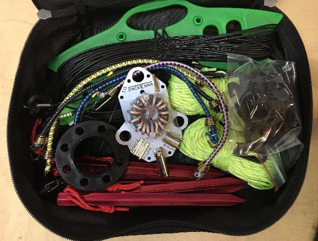
3 The PackTenna System The complete PackTenna system includes fiberglass support masts, wire antenna elements, base mounting hardware, feed points and accessories. This section describes each piece of the system and how it is used. Complete System 10 meter (32 ) fiberglass mast 4x 20m quarter wave wire elements 1:1 Feed point choke, 9:1 feed point UNUN, in-line RF choke Guy rings, guy lines, S-clips, ground stakes, mini bungee cords Coax and carry bag


 into the")
4 10 M (32 ) Telescoping Fiberglass Support Mast All antenna configurations require raising the antenna up in the air. The PackTenna mast telescopes out to a maximum length of about 32 feet. When collapsed, the mast is only 26 inches long. This makes it just the right size to stow in your luggage or strap to your backpack. Mast sections stay in place by gently twisting the sections together when extended. It is important to not pull the elements too hard so they don t pop out the ends. If this happens, just unscrew the bottom and insert the sections back where they belong. The mast tapers to a very small diameter solid fiberglass rod at the tip. The top ¼ of the antenna, about the last 8 feet are too light to mount a coax feed point but is normally used for the end of a quarter wave ground plane wire or end-fed wire antenna. TIP: An easy way to attach the wire to the tip of the mast is to remove the very last mast segment, the 4mm solid dowel, and slip the end of the wire element (with the female banana socket) into the end of the last element tube. The crimped ferrule forms a natural bend in the wire and makes a great way to secure the wire without any additional hardware. When using the coaxial feed points, mount them ¾ the way up the mast. This is at about 21 feet above the ground. At this point the mast diameter is about ½ and easily supports the coaxial balun feed point. TIP: If you are taking the mast on the trail and want to cut more weight, consider what antenna configuration you need and only take the mast sections necessary. If you are using an inverted vee, you can take out the last 4 or 5 sections because they cannot support the feed point balun anyway. If you are using the mast to support the end of a wire element and don t need the full 10 meter length, you can remove the necessary mast sections and leave the larger, lower sections at home.


5 Wire Antenna Elements The standard PackTenna elements are and are designed to be a quarter wave on 20 meters. The wire elements have strain relief loops and banana connectors on each end. The loops are attached with S-clips which are in turn connected to the balun feed point, other elements or ground stakes. The basic PackTenna is a linked dipole design. This makes it easy to clip multiple elements in series allowing for easy band switching. The S-clips take the strain of the antenna and banana connectors. The banana connectors are used to make the RF connection. The banana connectors have a high surface area and are gold plated to make excellent RF connections. For 20 meters, a pair of antenna elements can make a dipole, inverted vee, ground plane, etc. For 40 meters, simply clip two 20 meter elements in series. The high end that connects to the feed point uses a male banana connector. The opposite end has a female banana connector. This makes it very easy to tune the antenna in the field, if needed, by plugging in a short pigtail wire and trimming the length. This way you can precisely tune the antenna while not cutting the 20m wire element. The antenna will work


6 reasonably well on 15m as well when configured as a 40m dipole or vee because 15m is the 3 rd harmonic of 40m. A DIY antenna parts kit is also available with the same hardware to make it easy for you to make your own antennas in any configuration you like for any band. Base Mounting Hardware The fiberglass mast must have a solid base to support the antenna. The PackTenna system includes a guy kit for ground mounting the antenna. The guy system includes 8 guy lines. Each guy line is 10 long and has a line tensioner, and an S-clip. 3 guy lines are used to hold the base in place making the mast self supporting. An additional four guy lines are included for the ends of the wire elements providing 20 feed of guy line on each side. One spare guy line is included because, well, you can always use more hardware.. The guy kit includes 6 light weight ground stakes. Three for the mast support guy lines, two for the wire element ends and a spare. When using the PackTenna on hard ground, like an asphalt parking lot, it is much easier to use a portable tripod mount. The PackTenna mast can be attached to the tripod with mini-bungee cords included with the system. Just put at least two bungees around the mast and tripod center support. Additional guying may be required depending on the antenna load and weather conditions. Photo tripods or speaker stands can make good base mounts.


7 Guy Ring The guy ring will rest at about 9 above the ground and provides an excellent guyed base. When deploying the PackTenna in the inverted Vee configuration, the antenna wire elements provide additional guying capability.


8 Guying configuration Guy line tensioner 3 sided aluminum ground stake with paracord loop

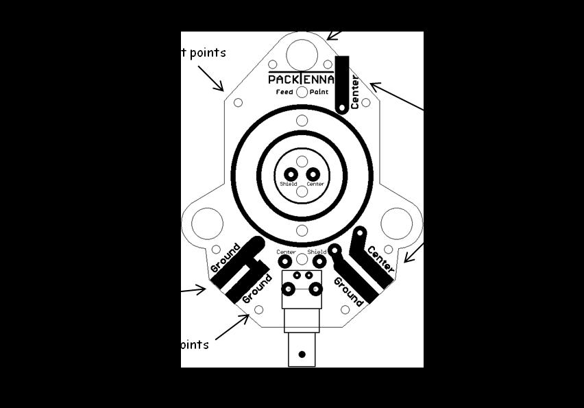
9 Feed Points The feed point is where the coax cable and antenna element wire comes together. This is the heart of the antenna. To deploy several different antenna configurations, the PackTenna system includes two types of feed points. A 1:1 current balun and a 9:1 UNUN. 1:1 Feed Point Balun A resonant antenna, like a half wave dipole, inverted vee or ground plane uses the balun to ensure there is no common mode current flowing back down the coax shield to the transmitter. These antennas do not require a tuner because the antenna is resonate for the band desired. The balun reduces or eliminates RFI at the radio and helps make the antenna more efficient. Standard PackTenna 1:1 Feed Point Balun PackTenna feed points include multiple banana sockets to connect the balun to the wire antenna elements. These connections are labeled Ground or Center The ground connections are connected together and the center connections are connected to each other. S-clips connect to the side lobes or top lobe and take the stress of the antenna element wire. The pigtail coming off the antenna wire element plug into the banana sockets.
10 TIP: When fielding an inverted vee or dipole, plug one wire element into a ground jack and one wire element into a center jack. TIP: When setting up a long wire, sloper, or vertical, connect the vertical radiator element to the center socket on the top and ground radials to one or more of the ground sockets. 9:1 UNUN This type of feed point is used to match the coax to an end-fed high impedance antenna. These can be either ½ wave resonate wires or random end fed wire antennas. The UNUN brings the feed point impedance down closer to the transmitter s 50 Ohm output impedance. A tuner is required to make these types of antennas work. 9:1 Feed Point UNUN
11

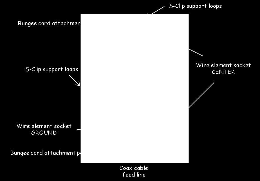
12 Mounting the Feed Point The feed point board mounts to the mast using mini bungee cords. This method allows you to attach the board tightly to the mast without crushing the mast material. The bungees also grip the mast so the feed point does not easily slide down the mast. There are six small holes that make convenient places to attach the bungees. Connect one end to the PCB, wrap the cord around the mast several times and connect the remaining end into another attachment point. Three large loops are provided on the sides and top to allow the S-clips to connect to the board. The S- clips provide a mechanical connection from the wire elements to the feed point. The wire elements plug into the feed point using mini banana plugs. There are 5 mini banana sockets mounted to the feed point board. Three of them are bussed together to ground and two are bussed together for the center wire of the feed line. The balun or UNUN on the feed point is between the feed line and the wire element banana sockets. The wire loops at the end of the wire elements clip into the S-clips and the male banana plugs plug into the sockets. When using the PackTenna in a dipole or inverted vee, connect one wire element to a ground point and the other wire element to the center point.

13 When using the PackTenna in an end-fed configuration, connect the long wire to one of the center points and optionally add one or more ground wires to the ground points. When using a vertical ground plane configuration, connect one or more ground radials to the ground points and the vertical element to the top center socket. The coax cable from the radio connects to the BNC connector at the bottom. Coax Cable We recommend 25 lengths of RG58 coax with BNC connectors. Use one length of coax when operating near the bottom of the mast. When operating farther from the mast, add another 25 section of coax with a BNC/BNC barred connector. Of course any 50 ohm coax will work. For general portable operations, we recommend RG58 because it s more robust than the thinner RG174 and it s smaller and lighter than the larger RG8X. For backpacking, while RG58 works fine, you may consider the thinner cables. For these smaller cables, we recommend RG316 because of it s mechanical strength. It is the same size and performance as RG174. The downside to the smaller cable is the higher losses, even at HF frequencies.

14 S-Clips The S-clip is a universally useful piece of hardware. These non-conductive clips are true multi-taskers. They are used to quickly connect wire elements to our feed points, connect guy lines together, and suspend feed points from a tree limb. Your imagination is the limit. Notice the holes in the side these are very handy places where you can thread antenna wire in and out for quick setups or manually tuning. You can also thread paracord through the hole and tie it off in a knot. Super light weight and strong, these clips are a great addition to your portable station. BNC Barrel Connector We recommend using 25 segments of RG58 coax with male BNC connectors on either end. The barrel connector is used to link multiple 25 segments together Optional Switch Link The switch link can be used instead of the banana connectors to make a linked dipole. The device is a little PCB with a slide switch that makes / breaks the connection in the antenna wire. The isolation is limited by the gap in the slides switches so care must be taken not to run very high power.

15 1:1 In-line current choke Common mode current can flow on the outside of the shield from the feed point back down to the shack. This can cause RF interference to your radios, accessories and other electronics. The 1:1 feed point balun and a resonant antenna greatly reduce common mode currents and the in-line choke is not typically needed for these configurations. However, end-fed and non-resonant antennas tend to induce common mode current flowing back down the coax shield. With these types of antennas we recommend using an in-line choke to minimize this interference. These problems are particularly common with higher power levels. Running QRP levels of 5 or 10 watts usually does not present a problem. When the power level is much higher, say watts, there is a much higher chance of causing RF interference. This can also happen when the radio is in the near field of the antenna. Moving away from the antenna and adding a choke will reduce the interference. It is not always possible, at higher power levels, to completely eliminate the interference.

16 Antenna Configurations The PackTenna system can be used to build many different antenna configurations. This section shows some of the most popular antennas used in portable operations. The diagrams are provided to explain the components needed and how to assemble them. These diagrams are not to scale but will give you the general idea. All the configurations only show the antenna components. It is assumed that there is some sort of base support. This would be a low set of guy lines, typically at the top of the second or third mast section. A ground stake or tripod can also be used as a base support. The base support method is not shown to keep the diagrams from getting to cluttered. So, which configuration of antenna is the best one? Every antenna configuration has pros and cons and many books have been written to explain the differences in great detail. For the portable operator, here is a very short set of recommendations 1. Horizontal antennas (dipole, inverted vee) are lower noise than verticals. Elevation will determine the angle of radiation. With a PackTenna the feed point will be at about 22 feet. For 20 meters and higher frequencies, this will provide good overall performance for both DX. On 40m with the antenna much closer to ground you will tend to have more local or regional communications because the radiation pattern will be higher. 2. A quarter wave ground plane will have a low angle of radiation so it will perform well as a DX antenna but tend to be noisier than a horizontal antenna. PackTenna is large enough to build a full size quarter wave ground plane for 20m and higher frequencies. You can also make a quarter wave ground plane for 40m but the feed point will be at the ground level. This will not be as efficient as a raised feed point on the 20m configuration. You can overcome some of the ground losses by adding several more ground radials on the ground itself.
17 3. End-Fed antennas, both the half wave and the non-resonant random wire have the big advantage of being the easiest antenna to set up quickly and have a very small foot print. It s easy to see how these antennas are very popular for portable operations where quick setup and take down is desirable. The disadvantage of these antennas is that they tend to be less efficient as compared to a tuned resonant antenna. These antennas tend to induce common mode current down the feed line back to the station. This is usually no problem at QRP levels but can be a problem at higher power levels. Adding an in-line common mode current choke can reduce this interference.
18 Inverted Vee An inverted vee is a half wave dipole antenna with a single center support and the ends angled towards the ground. This type of antenna performs similar to a traditional dipole in that it is horizontally polarized with a fairly omni-directional pattern. Because of the horizontal polarization, the inverted vee is typically quieter than a vertical. Inverted Vee s are popular for portable ops because, unlike a dipole, it only has one physical support mast required. The angle of the V is typically between 90 and 120 degrees and care must be taken to keep the ends of the elements off the ground by at least 2 to 3 feet and higher is better. A 1:1 balun is recommended at the feed point to ensure an efficient coupling to the antenna elements and to keep common mode currents from flowing back down the coax shield. When setting up the inverted vee, extend the mast to about 22. This is the point where the feedpoint will be attached. This elevation works well on 20m and higher frequencies with little ground interaction. It is also the point where the mast is still large enough to hold up the feed point and coax. The antenna elements will act as a high level guy lines as well to keep the antenna in position. The PackTenna elements are pre-cut as a quarter wave on 20 meters. On advantage of using a full size half wave antenna is that they tend to be fairly broad band. This means if it s tuned for the middle of the band it will work pretty well across the whole band. If you really want to tune the antenna even closer to your desired frequency you can add a tuning whisker. The wire elements have a male banana plug that goes at the end closest to the feed point. The opposite end has a female banana socket. This socket is used to link to another wire segment. You can make a simple tunig wire by soldering a male banana plug onto about one foot of antenna wire. Plug the short tuning wire at the end of the antenna and snip off an inch at a time until the antenna is perfectly tuned.

19 The inverted vee configuration is also very good for a multi-band 20/40 antenna. In the diagram above, you can see how putting two standard 20m quarter wave elements on each side and connecting the dipole links between them wil make it easy to swtich between a full size 20m or 40m inverted vee. When connecting the antenna elements to the feed point, insert one side into a banana socket marked Ground and the other wire element into the banana socket marketd Center
20 Half Wave Dipole The half wave dipole is the most common antenna found in ham radio and certainly the reference against which just about all other antennas are measured against. A dipole must be suspended at either end. This means you must find two strong anchor points. In addition to being a rather large antenna compared to other configurations, dipoles are not as popular in the field as other configurations. The PackTenna certainly can be deployed in a dipole configuration using the balun feed point and wire elements. Two PackTenna 30 fiberglass masts could be used to support a dipole as high up as about 22 feet. Beyond that point, the mast is too thin to provide enough support. The mast must be guyed very close to the point where the dipole connects to the guy ring to avoid bending the mast. We recommend that if you want to use the PackTenna in a dipole configuration you use a very rigid anchor point for the ends of the dipole such as a tree or building.
21 Quarter Wave Ground Plane The quarter wave ground plane has one quarter wave wire element in the vertical plane and one or more ground radials forming the counterpoise of the antenna. The quarter wave has the advantage of a low angle of radiation so it makes a good DX antenna. Although somewhat noisier than a dipole or inverted vee, the ground plane is a good performing resonant antenna. Ground planes can be ground mounted or elevated. Mounting the antenna with the base feed point at the ground level causes significant ground losses and makes the antenna less efficient. Elevating the whole antenna above ground so the feed point is at least 1/8 wave above the ground reduces ground losses and makes the antenna more efficient. From a practical point of view, with a 30 tall PackTenna mast, you can make an elevated ground plane for any band from 20 meters and up in frequency. This is the recommended configuration. It is an easy configuration to setup and using 3 ground radials will double as your guy lines to hold up the antenna. If you are making a larger antenna, say for 30m, 40m, or lower in frequency, you will have to put the feed point much closer to ground. While this will certainly work, adding more radials will help reduce ground losses. How many do you need? Ideally 8 or more would make a big difference so put out as many as you can. The length of radials for an elevated antenna makes a big difference in the tuning of the antenna. This includes the length, angle and proximity to the ground. When ground mounting your vertical, the length of the radials is not as critical.


22 End-Fed Half Wave The end-fed half wave or random wire antenna is very popular. This is because it is very quick to set up and take down and because it MUST be used with an antenna tuner, and can work on all bands. When running a non-resonant end-fed wire, make sure the antenna is non resonant on ANY ham band. The following lengths are good: because they don t land in a ham band. With the standard PackTenna wire element length of 16 10, it is a quarter wave on 20m so you will want to add additional wire. We recommend adding 12 feet of wire giving you a length of 29 which is a nice, large radiator and can be supported with a fully extended PackTenna mast. The impedance of the antenna at the end is high, often between Ohms, compared to the transmitters expected load of 50 Ohms. These antenna benefit from using a 9:1 UNUN to transform the impedance down to the range that your radio s antenna tuner can match.
23 9:1 UNUN matching transformer
24 Typical configuration for an end-fed antenna would have the radiator plugged into the Center connector and an optional ground wire connected to one of the Ground connectors. PackTenna Hardware Pack 8x 10 guy lines with tensioners 10x S-clips 5x Ground stakes Guy ring Mini bungee cords
25 Reference For the fanatic backpacker in all of us, here are the weights of each item in ounces 1:1 feed point balun 2.6 9:1 UNUN with large core 4.4 4x 20m wire elements & winder x guy line ' coax 9.7 Guy ring (each) mini bungees 2.7 In line choke m mast 43.0
Portable HF Antennas. Think Like A Backpacker. George - KJ6VU
 Portable HF Antennas Think Like A Backpacker George - KJ6VU WWW. HAMRADIO360.COM WWW. PACKTENNA.COM PODCAST www.kj6vu.com My Personal Goals Operate more HF Get out and hike more Improve my CW skills Build
1) Transmission Line Transformer a. First appeared on the scene in 1944 in a paper by George Guanella as a transmission line transformer, the 1:1
 Transmission Line Transformer a. First appeared on the scene in 1944 in a paper by George Guanella as a transmission line transformer, the 1:1") 1) Transmission Line Transformer a. First appeared on the scene in 1944 in a paper by George Guanella as a transmission line transformer, the 1:1 Guanella Balun is the basic building Balun building block.
1) Transmission Line Transformer a. First appeared on the scene in 1944 in a paper by George Guanella as a transmission line transformer, the 1:1 Guanella Balun is the basic building Balun building block.
Table of Contents. MFJ-1778 G5RV Multiband Antenna
 Table of Contents MFJ-1778 G5RV Multiband Antenna Introduction... 1 Theory Of Operation... 1 80 meter band:... 1 40 meter band:... 1 30 meter band:... 2 20 meter band:... 2 17 meter band:... 2 15 meter
THE W3FF HOMEBREW BUDDIPOLE
 THE W3FF HOMEBREW BUDDIPOLE A PORTABLE ANTENNA DESIGN FOR AMATEUR RADIO History of the Buddipole In January of 2000, I began experimenting with a walking portable ham station. Since then, thousands of
4 Antennas as an essential part of any radio station
 4 Antennas as an essential part of any radio station 4.1 Choosing an antenna Communicators quickly learn two antenna truths: Any antenna is better than no antenna. Time, effort and money invested in the
Portable Antenna Spike Mount (CHA SPIKE MOUNT) Operator s Manual
 Operator s Manual") Portable Antenna Spike Mount (CHA SPIKE MOUNT) Operator s Manual Nevada - USA WWW.CHAMELEONANTENNA.COM VERSATILE DEPENDABLE STEALTH BUILT TO LAST Table of Contents Introduction... 3 Parts of the Spike
Portable Antenna Spike Mount (CHA SPIKE MOUNT) Operator s Manual Nevada - USA WWW.CHAMELEONANTENNA.COM VERSATILE DEPENDABLE STEALTH BUILT TO LAST Table of Contents Introduction... 3 Parts of the Spike
HFp. User s Guide. Vertical. entenna. 7 MHz 30 MHz Amateur Radio Antenna Plus 6-Meters
 User s Guide HFp Vertical 7 MHz 30 MHz Amateur Radio Antenna Plus 6-Meters The Ventenna Co. LLC P.O. Box 2998, Citrus Heights, CA, 956 www.ventenna.com entenna Table of Contents The HFp Antenna -------------------------------------------------------------------
Chapter 6 Antenna Basics. Dipoles, Ground-planes, and Wires Directional Antennas Feed Lines
 Chapter 6 Antenna Basics Dipoles, Ground-planes, and Wires Directional Antennas Feed Lines Some General Rules Bigger is better. (Most of the time) Higher is better. (Most of the time) Lower SWR is better.
Model S9v Multiband Vertical Antenna Installation Guide
 Model S9v31 31 Multiband Vertical Antenna Installation Guide WARNING: INSTALLATION OF THIS PRODUCT NEAR POWERLINES IS DANGEROUS. FOR YOUR SAFETY, FOLLOW THE INSTALLATION DIRECTIONS. INTRODUCTION Thank
MFJ-2982 Feather-Lite 80-6 Meter Vertical Antenna
 MFJ-2982 Feather-Lite 80-6 Meter Vertical Introduction: The MFJ-2982 is a lightweight 31-foot fiberglass antenna designed to mount on any convenient post, mast, or a suitable wide-stance tripod such as
The first thing to realize is that there are two types of baluns: Current Baluns and Voltage Baluns.
 Choosing the Correct Balun By Tom, W8JI General Info on Baluns Balun is an acronym for BALanced to UNbalanced, which describes certain circuit behavior in a transmission line, source or load. Most communications
BRIEF GUIDE TO THE BUDDIPOLE ANTENNA SYSTEM. by David Haycock, KI6AWR
 BRIEF GUIDE TO THE BUDDIPOLE ANTENNA SYSTEM by David Haycock, KI6AWR Brief Guide to the Buddipole Antenna System by David Haycock, KI6AWR BRIEF GUIDE TO THE BUDDIPOLE ANTENNA SYSTEM by David Haycock, KI6AWR
Model S9v. 43 Multiband Vertical Antenna Installation Guide
 Model S9v 43 Multiband Vertical Antenna Installation Guide. WARNING: INSTALLATION OF THIS PRODUCT NEAR POWERLINES IS DANGEROUS. FOR YOUR SAFETY, FOLLOW THE INSTALLATION DIRECTIONS. INTRODUCTION Thank you
Portable Vertical Antenna Counterpoise Kit (CHA COUNTERPOISE KIT) Operator s Manual
 Operator s Manual") Portable Vertical Antenna Counterpoise Kit (CHA COUNTERPOISE KIT) Operator s Manual Nevada - USA WWW.CHAMELEONANTENNA.COM VERSATILE DEPENDABLE STEALTH BUILT TO LAST Table of Contents Introduction... 3
Portable Vertical Antenna Counterpoise Kit (CHA COUNTERPOISE KIT) Operator s Manual Nevada - USA WWW.CHAMELEONANTENNA.COM VERSATILE DEPENDABLE STEALTH BUILT TO LAST Table of Contents Introduction... 3
Portable or Emergency VHF Antennas Paul R. Jorgenson KE7HR
 For emergency or public service events it is often necessary to have more antenna than the rubber duck on your handheld VHF radio. Nearly ANY external antenna will provide more coverage for your handheld
Newcomers And Elmers Net: Wire Antennas Robert AK3Q
 Newcomers And Elmers Net: Wire Antennas 02-07-16 Robert AK3Q Wire antennas represent one of the greatest values in the radio hobby world. For less than the cost of a good meal out on the town you can buy
How My Black Widow Vertical Morphs into an Up & Outter Antenna By, Edward R Breneiser, WA3WSJ
 How My Black Widow Vertical Morphs into an Up & Outter Antenna By, Edward R Breneiser, WA3WSJ I really like to play radio in the great outdoors. In fact, the father away from people, the better for me
Alpha Delta Communications, Inc. Model DX-OCF Off-Center-Fed 7 Band Antenna
 Alpha Delta Communications, Inc. Model DX-OCF Off-Center-Fed 7 Band Antenna 75/80, 40, 20, 17, 12, 10, and 6 meters (50.0-51.0 MHz) NO TUNER REQUIRED! Installation Instructions One leg is 45 ft., the other
A short, off-center fed dipole for 40 m and 20 m by Daniel Marks, KW4TI
 A short, off-center fed dipole for 40 m and 20 m by Daniel Marks, KW4TI Version 2017-Nov-7 Abstract: This antenna is a 20 to 25 foot long (6.0 m to 7.6 m) off-center fed dipole antenna for the 20 m and
Antenna Design for FM-02
 Antenna Design for FM-02 I recently received my FM-02 FM transmitter which I purchased from WLC. I researched the forum on what antennas where being used by the DIY community and found a nice write-up
A Tri Band Antenna for 2 meters, 220 MHz, and 70cm Antenna Without Radials. By: Edison Fong (WB6IQN)
") A Tri Band Antenna for 2 meters, 220 MHz, and 70cm Antenna Without Radials By: Edison Fong (WB6IQN) Twenty years ago a single band handie talkie would have been adequate for emergency use since almost
A Tri Band Antenna for 2 meters, 220 MHz, and 70cm Antenna Without Radials By: Edison Fong (WB6IQN) Twenty years ago a single band handie talkie would have been adequate for emergency use since almost
The W3FF Portable Dipole
 The W3FF Portable Dipole This is the antenna I designed for my 'walking portable' station. It is a dipole constructed out of the plastic plumbing pipe CPVC. There are telescoping whips at the ends of each
6M HALO VERSON II + OPTIONAL 2M GROUND PLANE
 The halo is an omnidirectional, horizontally polarized antenna with about the same gain as a dipole but without the low elevation nulls off the ends (+5.5 to +3.5dBi variation for the Halo vs. +7.9 to
Page 1The VersaTee Vertical 60m, 80m Modular Antenna System Tutorial Manual
 Page 1The VersaTee Vertical 60m, 80m Modular Antenna System Tutorial Manual by: Lou Rummel, KE4UYP Page 1 In the world of low band antennas this antenna design is unique in many different ways. 1. It is
High Performance 40 Meters Vertical Without Radials
 High Performance 40 Meters Vertical Without Radials This shortened easy-to-build vertical, with no-radials, is made from surplus military camouflage poles. It has gain and wave angle comparable to a full-sized
PAC-12 Kit Contents. Tools Needed Soldering iron Phillips screwdriver Wire stripper Wrenches, 7/16 and 1/2 Terminal crimp tool Pliers Solder
 PAC-2 Kit Contents Part Quantity Screws: 8/32 x 3/8 Screws: 8-32 x 5/6 Screw: 8-32 x /4 #8 internal tooth washers #8 solder lug ring terminals Bolt: Aluminum, /4-20 x.5 /4 internal tooth washer Nut: Aluminum
Wire Antennas that WORK!
 2 Wire Antennas that WORK! A collection of details and descriptions of antennas based on Spiderbeam fiberglass poles, as described in greater detail on DJ0IPs Web Page: WWW.DJ0IP.DE Affordable DX Antennas
HFp. User s Guide. Vertical. entenna. 7 MHz 54 MHz Amateur Radio Antenna. The Ventenna Co. LLC P.O. Box 227 Huston, ID
 User s Guide HFp Vertical 7 MHz 54 MHz Amateur Radio Antenna The Ventenna Co. LLC P.O. Box 227 Huston, ID 83630 www.ventenna.com entenna Table of Contents The HFp Antenna -------------------------------------------------------------------
Installation Instructions Hustler 6-BTV Trap Vertical
 Installation Instructions Hustler 6-BTV Trap Vertical ASSEMBLY 1. Check the package contents against the parts list on page 2. 2. WARNING. Installation of this product near power lines is dangerous. For
M2 Antenna Systems, Inc. Model No: 2M HO LOOP
 M2 Antenna Systems, Inc. Model No: 2M HO LOOP SPECIFICATIONS: Model... 2M HO LOOP Frequency Range... 144 To 144.5 MHz Gain, Typical @ 10 ft.... 4 dbd @ 10 deg. Gain, 2 STK @ 82 & 132... 8 dbd @ 9 deg.
Technician License. Course
 Technician License Course Technician License Course Chapter 4 Lesson Plan Module - 10 Practical Antennas The Dipole Most basic antenna The Dipole Most basic antenna The Dipole Total length is ½ wavelength
Weekend Antennas No. 5 The "Compact Quad" Multiband Antenna
 Weekend Antennas No. 5 The "Compact Quad" Multiband Antenna When I relocated to Johannesburg I needed a new multiband HF antenna. Since I was staying in a rented house a tower was out of the question,
Installation Instructions Hustler 6-BTV Trap Vertical
 Installation Instructions Hustler 6-BTV Trap Vertical ASSEMBLY 1. Check the package contents against the parts list on page 2. 2. WARNING. Installation of this product near power lines is dangerous. For
Bob Brehm, AK6R Chief Engineer Palomar-Engineers.com
 Bob Brehm, AK6R Chief Engineer Palomar-Engineers.com HAMCON 2017 - September 2017 This presentation available on website Copyright 2013-2017 Palomar Engineers, Inc. End Fed Workshop Topics Popular End
MFJ-219/219N 440 MHz UHF SWR Analyzer TABLE OF CONTENTS
 MFJ-219/219N 440 MHz UHF SWR Analyzer TABLE OF CONTENTS Introduction...2 Powering The MFJ-219/219N...3 Battery Installation...3 Operation Of The MFJ-219/219N...4 SWR and the MFJ-219/219N...4 Measuring
User Guide for the Alpha S9v31 Antenna
 User Guide for the Alpha S9v31 Antenna Manufactured by: Alpha Antenna 1.888.482.3249 Website: http://alphaantenna.com User Guide Version 2.0 July 27, 2018 Page 1 Table of Contents Introduction... 3 Product
Bob Brehm, AK6R Chief Engineer Palomar-Engineers.com
 Bob Brehm, AK6R Chief Engineer Palomar-Engineers.com LAKESIDE - October 2017 This presentation available on website Copyright 2013-2017 Palomar Engineers, Inc. End Fed Workshop Topics Popular End Fed Antenna
INSTRUCTION MANUAL ORDER NO. V3R MODEL V3R. Collinear Gain Vertical for MHz
 ORDER NO. V3R MODEL V3R Collinear Gain Vertical for 216-225 MHz INSTRUCTION MANUAL General Description The new Hy-Gain V3R VHF antenna is a collinear 5/8-wave omnidirectional vertical antenna for the 216-225
Ten-Tec Model 3402 and 3403 Broadband Antennas Installation and Operation Manual PN 74393
 1. Introduction Ten-Tec Model 3402 and 3403 Broadband Antennas Installation and Operation Manual PN 74393 The Ten-Tec Model 3402 Broadband Terminated Vee Beam Antenna offers continuous coverage between
WCARES NEEDS YOU! CONSIDER MAKING A TECHNICAL PRESENTATION AT AN UPCOMING CHEW & CHAT MEETING LEARN SOMETHING NEW AND PRESENT
 WCARES NEEDS YOU! CONSIDER MAKING A TECHNICAL PRESENTATION AT AN UPCOMING CHEW & CHAT MEETING SHARE WHAT YOU KNOW LEARN SOMETHING NEW AND PRESENT IT CONTACT TIM AD4CJ AD4CJ@arrl.net 1 Transmission Line
Pacific Antenna 20 and 40M Lightweight Dipole Kit
 Pacific Antenna 20 and 40M Lightweight Dipole Kit Diagram showing configuration and approximate lengths 8 3 16 9 16 9 8 3 Description The Pacific Antenna lightweight dual band, trap dipole kit provides
ANTENNAS Wires, Verticals and Arrays
 ANTENNAS Wires, Verticals and Arrays Presented by Pete Rimmel N8PR 2 1 Tonight we are going to talk about antennas. Anything that will conduct electricity can be made to radiate RF can be called an antenna.
Technician Licensing Class. Antennas
 Technician Licensing Class Antennas Antennas A simple dipole mounted so the conductor is parallel to the Earth's surface is a horizontally polarized antenna. T9A3 Polarization is referenced to the Earth
Technician Licensing Class T9
 Technician Licensing Class T9 Amateur Radio Course Monroe EMS Building Monroe, Utah January 11/18, 2014 January 22, 2014 Testing Session Valid dates: July 1, 2010 June 30, 2014 Amateur Radio Technician
HexBeam Antenna. Equation 2, for 2.5 < b/w < 4: Zo = * LOG ( * (b/w) Zo = * LOG ( * 2.5) = 49.83Ω
 Zo = * LOG ( * 2.5) = 49.83Ω") HexBeam Antenna T here are numerous articles 1, 2, 3 on the design and construction of this popular 5-band broadband antenna and I decided to build one that utilizes all of the best features. Hub Most
HexBeam Antenna T here are numerous articles 1, 2, 3 on the design and construction of this popular 5-band broadband antenna and I decided to build one that utilizes all of the best features. Hub Most
Portable Magnetic Loop Antenna Version Two
 Portable Magnetic Loop Antenna Version Two The entire antenna assembled and hung up. Note the tuning head at the top matching unit at the bottom, with the spreader supported by the old felt tip pen lids
Using the Buddipole as a Balanced- Fed Doublet 1
 Using the Buddipole as a Balanced- Fed Doublet 1 Les Gasser, W9XC Version 4.1: July 15, 2011 Abstract The well- known Buddipole antenna is a "construction kit" commonly configured into an asymmetrical
The J-Pole Antenna. Gary Wescom
 The J-Pole Antenna Gary Wescom - 2018 Much has been written about the J-Pole antenna. A simple Google search will net days worth of reading material on the subject. That would tend to indicate this paper
INSTRUCTION MANUAL. Specifications Electrical. Front-To-Back Ratio VSWR at Resonance Less than 1.5:1 Nominal Impedance. Mechanical
 300 Industrial Park Road, Starkville, MS 39759 Ph: (662) 323-8538 FAX: (662) 323-6551 TH-3JRS Tri-band HF 3 Elements Beam Covers 10, 15 and 20 Meters INSTRUCTION MANUAL WARNING Installation of this product
G3EJS portable antenna for the IC-703
 G3EJS portable antenna for the IC-703 Following a comment I have received several emails reqesting details of my antenna, so I have very quickly put this together, not very good, but sufficient for anyone
Least understood topics by most HAMs RF Safety Ground Antennas Matching & Feed Lines
 Least understood topics by most HAMs RF Safety Ground Antennas Matching & Feed Lines Remember this question from the General License Exam? G0A03 (D) How can you determine that your station complies with
Emergency Antennas. Presented by Ham Hilliard W4GMM
 Emergency Antennas Presented by Ham Hilliard W4GMM Dipole antenna Vertical antenna Random wire antenna Dipole antenna The half wave dipole antenna consists of a conductive wire or rod that is half the
AD5X. Low Cost HF Antennas & Accessories. Phil Salas - AD5X Phil Salas AD5X. Richardson, Texas
 Low Cost HF Antennas & Accessories Phil Salas - AD5X ad5x@arrl.net PVC Tubing PVC pipe: Considers the inside diameter (ID) of the pipe. For PVC pipe (schedule 40): 1/2" PVC pipe has an ID of 0.6" and an
4/29/2012. General Class Element 3 Course Presentation. Ant Antennas as. Subelement G9. 4 Exam Questions, 4 Groups
 General Class Element 3 Course Presentation ti ELEMENT 3 SUB ELEMENTS General Licensing Class Subelement G9 Antennas and Feedlines 4 Exam Questions, 4 Groups G1 Commission s Rules G2 Operating Procedures
BUILD A HIGH PERFORMANCE TWO ELEMENT TRI-BAND CUBICAL QUAD. By Bob Rosier K4OCE INTRODUCTION THEORY AND GENERAL INFORMATION
 BUILD A HIGH PERFORMANCE TWO ELEMENT TRI-BAND CUBICAL QUAD INTRODUCTION By Bob Rosier K4OCE Lots of DX can be worked with a dipole at the QRP level, however, a beam will obviously give you additional gain
Miniature Magnetic Loops By David Posthuma, WD8PUO
 Miniature Magnetic Loops By David Posthuma, WD8PUO Application Notes and Articles A General Overview After several years of curiosity and several months of research, I recently built two magnetic loops.
A Folding 5-Element Yagi for 144 MHz
 A Folding 5-Element Yagi for 144 MHz Steve Kavanagh, VE3SMA, April 2017 1. Introduction I have found antennas which fold up quickly to take less space in the car to be useful in VHF/UHF portable operating.
Last year I described several Low Band RX antennas that would enable you to hear DX stations on 160, 80 and 40M. This will show you how to build
 Last year I described several Low Band RX antennas that would enable you to hear DX stations on 160, 80 and 40M. This will show you how to build transmit antennas that will help you break the pileups!
A Folding 11-Element Yagi for 432 MHz
 A Folding 11-Element Yagi for 432 MHz Steve Kavanagh, VE3SMA, October 2015 1. Introduction For portable VHF/UHF operation I have found it convenient at times to have some antennas which fold up quickly
The Reverse Polarity TNC(m) RF connector can be easily secured or removed from equipment in the field by a single gloved hand, no tools required.
 RF connector can be easily secured or removed from equipment in the field by a single gloved hand, no tools required.") Overview Southwest Antennas is a half wave dipole omni antenna with a frequency range of 1.35 to 1.40 GHz and 2.15 dbi of peak gain. This product features an integrated RF bandpass filter to help eliminate
Overview Southwest Antennas is a half wave dipole omni antenna with a frequency range of 1.35 to 1.40 GHz and 2.15 dbi of peak gain. This product features an integrated RF bandpass filter to help eliminate
Pacific Antenna 20 and 40M Lightweight Dipole Kit
 Pacific Antenna 20 and 40M Lightweight Dipole Kit Diagram showing configuration and approximate lengths 8 6 16 9 16 9 8 6 Description The Pacific Antenna lightweight dual band, trap dipole kit provides
Pacific Antenna 20 and 40M Lightweight Dipole Kit
 Pacific Antenna 20 and 40M Lightweight Dipole Kit Antenna diagram showing configuration and lengths when assembled 7 8 16 9 16 9 Description The Pacific Antenna lightweight dual band dipole kit provides
Super Antenna Model YP-1 OBSOLETE NOT SUPPORTED
 Super Antenna Model YP-1 OBSOLETE NOT SUPPORTED 6 Band Rotatable Dipole 20, 15, 17, 12, 10, 6M The SUPERANTENNA YP1 Rotatable Dipole is the driven element of the YP3 Yagi by Super Antenna Congratulations.
Optimizing Your Stations Performance
 Optimizing Your Stations Performance A few hints / techniques, recommendations for getting the most RF out to the Antenna from your HF, VHF / UHF station. Tonights Presenters: Doug Theriault NO1D John
INSTRUCTION MANUAL. Model 18AVQII Five Band Vertical Antenna 10, 15, 20, 40, 80 Meter
 Model 18AVQII Five Band Vertical Antenna 10, 15, 20, 40, 80 Meter 308 Industrial Park Road Starkville, MS 39759 (662) 323-9538 Fax: (662) 323-5803 INSTRUCTION MANUAL General Description The Hy-Gain 18AVQII
Small Magnetic Loops: A Beginner s Guide WOW! This is a very different antenna!
 Small Magnetic Loops: A Beginner s Guide WOW! This is a very different antenna! Dave Wickert, AE7TD Lake Washington Ham Club November 2018 Meeting 10-Nov-2018 Dayton Hamvention 2017 History Full Size Loops
MFJ-969 Versa Tuner II Instruction Manual
 MFJ-969 Versa Tuner II Instruction Manual General Information The MFJ-969 is a 300 watt RF output power antenna tuner that will match any transmitter or transceiver to virtually any antenna. Peak or average
Portable Antenna Systems
 Portable Antenna Systems Dr. John A. Allocca, WB2LUA www.wb2lua.com 3/6/16 System 1 - HF / VHF / UHF Tripod VHF/UHF Antenna Dipole Mount HF Hamstick Case! 1 of! 5 Introduction This antenna configuration
The Fabulous Dipole. Ham Radio s Most Versatile Antenna
 The Fabulous Dipole Ham Radio s Most Versatile Antenna 1 What is a Dipole? Gets its name from its two halves One leg on each side of center Each leg is the same length It s a balanced antenna The voltages
MFJ-949E. tuner antenowy skrzynka antenowa. Instrukcja obsługi. importer:
 Instrukcja obsługi MFJ-949E tuner antenowy skrzynka antenowa importer: PRO-FIT Centrum Radiokomunikacji InRadio ul. Puszkina 80 92-516 Łódź tel: 42 649 28 28 e-mail: biuro@inradio.pl www.inradio.pl MFJ-949E
Build the PAC-12 Antenna
 Build the PAC-12 Antenna a multi-band portable vertical designed by KA5DVS Here s an award-winning, easy-to-homebrew, multi-band portable vertical antenna designed by long-time antenna aficionado James
Array Solutions 350 Gloria Rd Sunnyvale, TX USA PHN FAX
 Array Solutions 350 Gloria Rd Sunnyvale, TX 75182 USA PHN 972 203 2008 FAX 972 203 8811 E-MAIL sales@arraysolutions.com Model AS-AYL-4 4-way K9AY Loop System This is the popular K9AY Loop receiving antenna,
4/25/2012. Supplement T9. 2 Exam Questions, 2 Groups. Amateur Radio Technician Class T9A: T9A: T9A: T9A:
 Amateur Radio Technician Class Element 2 Course Presentation ti ELEMENT 2 SUB-ELEMENTS Technician Licensing Class Supplement T9 Antennas, Feedlines 2 Exam Questions, 2 Groups T1 - FCC Rules, descriptions
COAXIAL TRANSMISSION LINE COMMON-MODE CURRENT
 COAXIAL TRANSMISSION LINE COMMON-MODE CURRENT Introduction Coaxial transmission lines are popular for their wide frequency bandwidth and high resistance to electromagnetic interference (EMI). Coax cables
The EMCOMM Easytenna
 The EMCOMM Easytenna This document will detail how to build an easy to install multiband dipole type antenna for emergency communications using the NVIS propagation mode. History The NVIS mode is one in
Array Solutions OCF Series Dipoles
 OCF Series Dipoles Fig 1 Thank you and congratulations on your purchase of the, Off- Center Fed HF Dipole Antenna System. This antenna was built with the same quality workmanship and attention to detail
The quality you expect at the price you want to pay. Available at: 1 (888) (866)
 (866)") The quality you expect at the price you want to pay Available at: www.wirelessource.ca 1 (888) 430-0660 1 (866) 244-4844 October 2014 VHF Mobile Antennas... P1-5 UHF Mobile Antennas... P6-9 CB Mobile Antennas...
The quality you expect at the price you want to pay Available at: www.wirelessource.ca 1 (888) 430-0660 1 (866) 244-4844 October 2014 VHF Mobile Antennas... P1-5 UHF Mobile Antennas... P6-9 CB Mobile Antennas...
Users Manual. 200W HF/50MHz Band Auto Antenna Tuner. Model HC-200AT
 Users Manual 200W HF/50MHz Band Auto Antenna Tuner Model HC-200AT Caution 1. Never remove or open the tuner cover while transmitting. When there is RF in the circuits of the tuner, there will be high voltage
The HAM Radio Operator's Antenna HANDBOOK by Buck Rogers ( K4ABT, for over 60 years)
") 1 of 29 8/27/2007 8:20 AM Monday, August 27, 2007 Tell your friends, you found it at: Serving HAM Radio since 1959, On the Web Since 1995 Order Toll Free Monday through Friday, 9 am to 4 pm, 1 800 726
1 of 29 8/27/2007 8:20 AM Monday, August 27, 2007 Tell your friends, you found it at: Serving HAM Radio since 1959, On the Web Since 1995 Order Toll Free Monday through Friday, 9 am to 4 pm, 1 800 726
VHF and UHF Antennas for QRP Portable Operation. Prepared for the QRP forum at Pacificon2011 by KK6MC James Duffey October 15, 2011
 VHF and UHF Antennas for QRP Portable Operation Prepared for the QRP forum at Pacificon2011 by KK6MC James Duffey October 15, 2011 Overview Get on the air from portable locations with simple and effective
Assembly Instructions for the 1.5 Watt Amplifier Kit
 Assembly Instructions for the 1.5 Watt Amplifier Kit 1.) All of the small parts are attached to a sheet of paper indicating both their value and id. 2.) Leave the parts affixed to the paper until you are
User Guide. For. Alpha Antenna ProMaster
 User Guide For Alpha Antenna ProMaster Manufactured by: Alpha Antenna 1.888.482.3249 Website: http://alphaantenna.com User Guide Version 2.5 October 2, 2016 Page 1 Introduction Thank you for your support
A Relatively Simple160/80 No Tune/No Switch Dual CW Band Trap Antenna Using the Spiderbeam Mast
 A Relatively Simple160/80 No Tune/No Switch Dual CW Band Trap Antenna Using the Spiderbeam Mast This project originated with my request to the Contesting Top Band forum for thoughts on a transportable
Antenna. NO5V Rick Bono
 Portable End Fed Half Wave Antenna NO5V Rick Bono October 15, 2016 Overview Develop a Portable End Fed Half Wave Antenna Portable and easy to deploy Multiband capability Resonant Antenna No Tuner Needed!
INSTRUCTION MANUAL. Model 18AVQII Five Band Vertical Antenna 10, 15, 20, 40, 80 Meter. General Description. Theory of Operation
 Model 18AVQII Five Band Vertical Antenna 10, 15, 20, 40, 80 Meter 308 Industrial Park Road Starkville, MS 39759 (662) 323-9538 Fax: (662) 323-5803 INSTRUCTION MANUAL General Description The Hy-Gain 18AVQII
ELECRAFT AX-LINE OWNER S MANUAL AXB1 WHIP BIPOD AX1 DUAL BAND (+) WHIP ANTENNA AXT1 TRIPOD ADAPTER. Page 5. Page 2. Page 6
 WHIP ANTENNA AXT1 TRIPOD ADAPTER. Page 5. Page 2. Page 6") ELECRAFT AX-LINE OWNER S MANUAL AXB1 WHIP BIPOD Page 5 AX1 DUAL BAND (+) WHIP ANTENNA Page 2 AXT1 TRIPOD ADAPTER Page 6 E740330 Rev. B2, 4 Oct. 2018 Copyright 2018, Elecraft, Inc. All rights reserved 1
ELECRAFT AX-LINE OWNER S MANUAL AXB1 WHIP BIPOD Page 5 AX1 DUAL BAND (+) WHIP ANTENNA Page 2 AXT1 TRIPOD ADAPTER Page 6 E740330 Rev. B2, 4 Oct. 2018 Copyright 2018, Elecraft, Inc. All rights reserved 1
MFJ-1762 Instruction Manual
 MFJ-1762 Instruction Manual INTRODUCTION Thank you for purchasing the MFJ-1762 three-element six-meter Yagi. The MFJ-1762 is a light-weight directional antenna especially designed for installation with
Feed Line Currents for Neophytes.
 Feed Line Currents for Neophytes. This paper discusses the sources of feed line currents and the methods used to control them. During the course of this paper two sources of feed line currents are discussed:
9 Element Yagi for 2304 MHz
 9 Element Yagi for 2304 MHz Steve Kavanagh, VE3SMA Design Dipole-based Yagi designs for 2304 MHz are rare, partly because they are a bit tricky to build and partly because the loop yagi has completely
BUILD A SHORTWAVE ANTENNA "The Search For The Perfect Shortwave Antenna" by N4UJW Webmaster Hamuniverse.com
 BUILD A SHORTWAVE ANTENNA "The Search For The Perfect Shortwave Antenna" by N4UJW Webmaster Hamuniverse.com THE MULTIBAND LONG WIRE SHORTWAVE ANTENNA A Much Better But More Complicated Antenna This antenna
A TRANSMISSION LINE BALANCE TEST METER
 by Lloyd Butler VK5BR with modifications by Phil Storr VK5SRP. Here is a simple meter to check the balance of currents running in the two legs of a transmission line. It can be used to check the balance
DO NOT COPY. Basic HF Antennas. Bill Shanney, W6QR
 Basic HF Antennas Bill Shanney, W6QR When I was first licensed in 1961 I didn t know much about antennas. I put up the longest wire that fit on my parent s lot at the lofty height of 25 and fed it with
MFJ-249B HF/VHF SWR ANALYZER
 TABLE OF CONTENTS MFJ-249B... 2 Introduction... 2 Powering The MFJ-249B... 3 Battery Installation... 3 Alkaline Batteries... 3 NiCd Batteries... 4 Power Saving Mode... 4 Operation Of The MFJ-249B...5 SWR
HFp. User s Guide. Vertical. entenna. 7 MHz 30 MHz Amateur Radio Antenna
 User s Guide HFp Vertical 7 MHz 30 MHz Amateur Radio Antenna The Ventenna Co. LLC P.O. Box 2998, Citrus Heights, CA, 95611 www.ventenna.com entenna Table of Contents The HFp Antenna -------------------------------------------------------------------
CVARC 4:1 Balun Project Kit by AE6YC
 CVARC 4:1 Balun Project Kit by AE6YC New to the amateur radio world or have been around long enough to be considered an old timer, whichever you will never forget the first kit or homebrew project you
Tactical Dipole (CHA TD) Operator s Manual
 Operator s Manual") Tactical Dipole (CHA TD) Operator s Manual California - USA WWW.CHAMELEONANTENNA.COM VERSATILE DEPENDABLE STEALTH BUILT TO LAST Table of Contents Introduction... 3 HF Propagation... 3 Parts of the Antenna...
Tactical Dipole (CHA TD) Operator s Manual California - USA WWW.CHAMELEONANTENNA.COM VERSATILE DEPENDABLE STEALTH BUILT TO LAST Table of Contents Introduction... 3 HF Propagation... 3 Parts of the Antenna...
M2 Antenna Systems, Inc. Model No: 2M4
 M2 Antenna Systems, Inc. Model No: 2M4 SPECIFICATIONS: Model... 2M4 Frequency Range... 144 To 148 MHz *Gain... 9.6 dbi Front to back... 20 db Typical Beamwidth... E=54 H=74 Feed type... T Match Feed Impedance....
Array Solutions. Model AS-AYL-4 4-way K9AY Loop System
 Array Solutions Model AS-AYL-4 4-way K9AY Loop System This is the popular K9AY Loop receiving antenna, as described in the September 1997 issue of QST, The K9AY Terminated Loop-A Compact, Directional Receiving
Cray Valley Radio Society. Real Life Wire Antennas
 Cray Valley Radio Society Real Life Wire Antennas 1 The basic dipole The size of an antenna is determined by the wavelength of operation In free space: ~3x10 8 m/s Frequency x Wavelength = Speed of Light,
CP6A. 6 Band Trap Vertical 75-6m
 CP6A 6 Band Trap Vertical 75-6m Instruction Sheet The CP6A is a multi-band trap-vertical antenna for HF bands, covering the 75*, 40, 20, 15, 10m & 6m amateur bands. Made from heavy duty aluminum, the CP6A