WCARES NEEDS YOU! CONSIDER MAKING A TECHNICAL PRESENTATION AT AN UPCOMING CHEW & CHAT MEETING LEARN SOMETHING NEW AND PRESENT
|
|
|
- Hilda Houston
- 5 years ago
- Views:
Transcription
1 WCARES NEEDS YOU! CONSIDER MAKING A TECHNICAL PRESENTATION AT AN UPCOMING CHEW & CHAT MEETING SHARE WHAT YOU KNOW LEARN SOMETHING NEW AND PRESENT IT CONTACT TIM AD4CJ AD4CJ@arrl.net 1
2 Transmission Line Transformers Chokes, Baluns and Ununs A WCARES presentation based upon information garnered from books and the internet from Amidon, Wikipedia, Jerry Sevick W2FMI, Tom Rauch W8JI, and technical notes from DX Engineering and Balun Designs. 2
3 Background: The term Transmission Line Transformer first appeared on the scene in 1944 in a paper by George Guanella as a transmission line transformer. The 1:1 Guanella Balun is the basic building Balun building block. 3
4 Then the 4:1 Unun was presented by Clyde Ruthroff in
5 Then in 1978 Joe Reisert W1JR enhanced the 1:1 balun idea further by winding that coil of coaxial transmission-line onto a toroid-core. This formed a Choke Balun. 5
6 Balun is an acronym for : BALanced to Unbalanced Unun is an acronym for: Unbalanced to Unbalanced 6
7 What does balanced and unbalanced mean? Ground (zero volts) Ground (zero volts) Twin Lead The voltages are balanced with respect to ground. Coax The voltages are unbalanced with respect to ground. 7
8 When a ground plane is present, we really have three conductors, forming a multiconductor transmission line, and this system supports two different modes Differential mode (desired) Common mode (undesired) The differential and common modes on a twin lead over ground For the common mode, both conductors of the transmission line act as one net conductor, while the ground plane acts as the other conductor (return path for the current). 8
9 Differential mode: currents are equal and opposite Ground Common mode: a net current flows on the two conductors Ground 9
10 If the two terminals of the load or source do not carry equal currents, some current will flow in a loop through the ground or along the outside of the shield. The outside of the shield is isolated by skin effect in the conductor wall. At radio frequencies the outside of the shield can be treated as an independent conductor connected to the inside shield at the ends of the coax. Most coaxial baluns make the outside shield connection a high impedance while not disturbing the inside operation. 10
11 Coaxial line currents If you try to feed a dipole antenna directly with coax, there will be a common mode current on the coax. No balun 11


12 A common- mode choke balun, for example, performs the balun funcdon by pueng impedance in the path of common- mode currents and is therefore a balun. 12

13 You can actually measure the common mode current on the outer shield of coaxial cable With a clamp-on RF Current Meter The MFJ-854 RF Current Meter reads true RF current. It can accurately measure actual RF currents flowing in antenna elements, radials, ground wires and on the outside of coax feedlines. 13


14 6:1 1:4 GUANELLA CURRENT BALUN 1:1 Dipole Feedpoint 1:1 Choke Balun 14


15 A bifilar winding is often used to improve the coupling between the primary and secondary of the transformer. A bifilar winding is the winding in close proximity of the primary and secondary wires over the same core. Low Power 4:1 Bifilar High Power 4:1 Bifilar Low Power 9:1 Trifilar 15
16 A common misconception and when using a loop, doublet or double extended Zep (and several others) for multiband operation requires a high ratio balun (6:1, 9:1, 12:1) to manage the transition from high impedance ladder line / open wire feedline to coax. An example would be the primary band a full size loop is cut for. Typically this will have a ohm feedpoint impedance and when divided by the ratio of the balun, i.e. 12:1 (if trying to match 600 ohm open wire) the resulting 8-10 ohms is impossible for all but the absolute best tuner to match. This problem can be even worse for doublets. If the doublet is cut for resonance on the primary or lowest band, the feedpoint impedance will be around ohms and the resulting impedance, after a high ratio balun, will be even lower than a similar loop antenna. The solution is using a balun with a much lower ratio such as a 1:1 or a 4:1 which will transform the balanced line to the unbalanced coax. 16
17 USING LADDER LINE WITH BALUNS TO CREATE A LOW LOSS TRANSMISSION LINE The RF power loss of 450Ω ladder line is lower than the loss of all 50Ω and 75Ω commercial hard line and CATV hardline cables 7/8" and smaller, and is equal to the loss of 1-1/4" hardline! (Loss figures from The ARRL Antenna Book) The loss of 450Ω ladder line is typically 1/10 of the loss of RG

18 When a balun or unun is wound correctly, a higher power rating will also mean a higher efficiency, low SWR and excellent overall Return Loss. Consequently, if you're a QRP operator running 5 or 10 watts, the best choice for you may well be the balun rated at 3 or 5kW. Of course this is usually impractical if your intended use is portable operation and want something small and light, but for a permanent installation the higher power is a much better choice. Keep in mind this may not be the case when using an inexpensive balun rated at high power. It is almost impossible to build a $20-30 balun that also offers high efficiency. 18
 to dipole antennas")
19 Baluns are used to connect coax (unbalanced line) to dipole antennas (balanced). 19
20 20
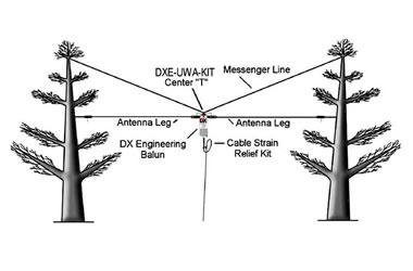
21 Ladder Line or Open Wire fed Dipoles or Doublets This is a popular antenna system. A simple muld- band dipole may be constructed by first choosing the lowest band on which operadon is desired. The overall length of the muld- band dipole antenna should be shorter than one- half wavelength. For best efficiency, ladder line feed and a good antenna tuner with balanced connecdons are required. The ideal balun is a 1:1 rado DX Engineering special applicadon tuner balun. It can be connected through a short length of coaxial cable to an unbalanced tuner for tuning the different bands. Dave, KI4PSR has and antenna similar to this. 21
22 ODD ONE EIGHTH WAVELENGTHS Ladder feedline for a multi-band dipole must be in odd multiple lengths of 1/8 wavelength on the lowest operating frequency. 22
23 Long- Wire Antennas Long wire antennas are typically horizontal antennas, fed at one end, and well over 1/2- wavelength long at the lowest operadng frequency. The impedance of a long wire antenna varies as the frequency is changed, but the normally accepted values are from a few hundred to a few thousand ohms depending on length, height, ground condidons and frequency. A 4:1 balun should be used in this installadon. The counterpoise length should be ¼ wave on the lowest frequency planned. Ed, WB4RHQ has an antenna like this. 23
24 Shorter End Fed Antennas Antennas that are typically horizontal antennas, fed at one end, and less than 1/2- wavelength long at the lowest operadng frequency. According to Balun Designs, a 9:1 unun is used. Please keep in mind this design is a compromise antenna and intended primarily for use by those living in restricted antenna areas or for temporary / emergency installadons where simplicity and broad HF coverage is important. Recommended Wire Lengths (in feet) for Coverage of 160m through 10m Tim, AD4CJ has an 88.5 antenna like this. 24

25 The True or Conventional Windom antenna, shown below, is fed with a single-wire line, and fed as an unbalanced system against a reasonable RF ground or counterpoise. The feed is similar to a longwire antenna, except the horizontal wire is fed with a few percent offset from the center. The best balun for both antennas, assuming they operated where standing waves on the feed system are low, are 4:1 baluns. 25
26 Horizontal Full-Wave Loop: The best balun for operation at resonance is a 4:1 ratio current balun. Vertical Full-Wave Loop: The best balun for operation at resonance is a 2:1 ratio current balun. (I need to build one for my 20M Daffy Dave s Delta Loop project!) For ground mounted quarter-wave verticals, the best device for this application is a 1:1 ratio current choke. 26

27 DON T BOTHER WITH ONE OF THESE! This is a classic "Ugly balun" or air core solenoid balun. They CAN work, however because capacitance in the coil is quite high they are self-resonant tank circuits. This means that they can present quite useful impedance on a couple of bands at most, but otherwise may be all but invisible on other bands. They can be strung together along the coax, but you end up using a lot of extra coax that equates to more loss, and it's far more expensive than just buying a proper toroid for $5. 27
28 Many thanks to Balun Designs for their generosity: Hi Dave, For your teaching use we will sell two of the kits to you for $30 each plus shipping so a total of $70.90 complete. 28
29 WCARES NEEDS YOU! CONSIDER MAKING A TECHNICAL PRESENTATION AT AN UPCOMING CHEW & CHAT MEETING SHARE WHAT YOU KNOW LEARN SOMETHING NEW AND PRESENT IT CONTACT TIM AD4CJ AD4CJ@arrl.net 29

30 Balun Designs, in collaboration with Fair Rite products, has developed what we consider to be the best single core 1:1 feedline isolation balun available today. By reviewing the scans shown below you can see what we're referring to. Notice how the level of choking impedance ramps up very quickly developing 3100 ohms on 160m and continues at even higher levels across the full HF spectrum. This is a very difficult level to achieve and maintain for a single core balun and is truly exceptional. What s more, the transformation, SWR and return loss are near perfect. This balun is unique in the marketplace today. 30
1) Transmission Line Transformer a. First appeared on the scene in 1944 in a paper by George Guanella as a transmission line transformer, the 1:1
 Transmission Line Transformer a. First appeared on the scene in 1944 in a paper by George Guanella as a transmission line transformer, the 1:1") 1) Transmission Line Transformer a. First appeared on the scene in 1944 in a paper by George Guanella as a transmission line transformer, the 1:1 Guanella Balun is the basic building Balun building block.
1) Transmission Line Transformer a. First appeared on the scene in 1944 in a paper by George Guanella as a transmission line transformer, the 1:1 Guanella Balun is the basic building Balun building block.
ARNSW Balun Day. Balun construction
 ARNSW Balun Day Balun construction Typical Baluns All built from locally available components. Balun uses Most baluns are used to match the 50Ω output of a transceiver to an antenna. A centre fed dipole
The first thing to realize is that there are two types of baluns: Current Baluns and Voltage Baluns.
 Choosing the Correct Balun By Tom, W8JI General Info on Baluns Balun is an acronym for BALanced to UNbalanced, which describes certain circuit behavior in a transmission line, source or load. Most communications
and Related Topics W7KVI, HARC Original: 3/26/16
 Baluns, Ununs, and Related Topics W7KVI, HARC Original: 3/26/16 This Presentation Informal & brisk - 52 slides (too many unless you re an enthusiast!) Discussion encouraged if not extensive, interrupt
Cray Valley Radio Society. Real Life Wire Antennas
 Cray Valley Radio Society Real Life Wire Antennas 1 The basic dipole The size of an antenna is determined by the wavelength of operation In free space: ~3x10 8 m/s Frequency x Wavelength = Speed of Light,
Jacques Audet VE2AZX. Nov VE2AZX 1
 Jacques Audet VE2AZX VE2AZX@amsat.org Nov. 2006 VE2AZX 1 - REASONS FOR USING A BALUN - TYPES OF BALUNS - CHECK YOUR BALUN WITH AN SWR ANALYZER - MEASURING THE IMPEDANCE OF A NUMBER OF FERRITES - IMPEDANCE
Chapter 6 Antenna Basics. Dipoles, Ground-planes, and Wires Directional Antennas Feed Lines
 Chapter 6 Antenna Basics Dipoles, Ground-planes, and Wires Directional Antennas Feed Lines Some General Rules Bigger is better. (Most of the time) Higher is better. (Most of the time) Lower SWR is better.
COAXIAL TRANSMISSION LINE COMMON-MODE CURRENT
 COAXIAL TRANSMISSION LINE COMMON-MODE CURRENT Introduction Coaxial transmission lines are popular for their wide frequency bandwidth and high resistance to electromagnetic interference (EMI). Coax cables
Table of Contents. MFJ-1778 G5RV Multiband Antenna
 Table of Contents MFJ-1778 G5RV Multiband Antenna Introduction... 1 Theory Of Operation... 1 80 meter band:... 1 40 meter band:... 1 30 meter band:... 2 20 meter band:... 2 17 meter band:... 2 15 meter
DO NOT COPY. Basic HF Antennas. Bill Shanney, W6QR
 Basic HF Antennas Bill Shanney, W6QR When I was first licensed in 1961 I didn t know much about antennas. I put up the longest wire that fit on my parent s lot at the lofty height of 25 and fed it with
What is a BALUN or UNUN:
 What is a BALUN or UNUN: A device to connect different types of antennas to various feed lines. Can transform impedances, choke common mode or change balanced to unbalanced BALUN Balanced to Unbalanced
The design of Ruthroff broadband voltage transformers M. Ehrenfried G8JNJ
 The design of Ruthroff broadband voltage transformers M. Ehrenfried G8JNJ Introduction I started investigating balun construction as a result of various observations I made whilst building HF antennas.
End Fed Half Wave Antenna Coupler
 End Fed Half Wave Antenna Coupler The finished End Fed Half Wave antenna coupler. Centre fed half wave dipoles make great, simple and effective antennas for the HF bands. Sometimes however, the centre
Antenna Design for FM-02
 Antenna Design for FM-02 I recently received my FM-02 FM transmitter which I purchased from WLC. I researched the forum on what antennas where being used by the DIY community and found a nice write-up
ANTENNA BASICS FOR BEGINNERS
 ANTENNA BASICS FOR BEGINNERS PART 2 -DIPOLES DIPOLES -General MULTIBAND DIPOLES RF CHOKES 1 DIPOLES Several different variations of the dipole are also used, such as the folded dipole, short dipole, cage
Newcomers And Elmers Net: Wire Antennas Robert AK3Q
 Newcomers And Elmers Net: Wire Antennas 02-07-16 Robert AK3Q Wire antennas represent one of the greatest values in the radio hobby world. For less than the cost of a good meal out on the town you can buy
The Fabulous Dipole. Ham Radio s Most Versatile Antenna
 The Fabulous Dipole Ham Radio s Most Versatile Antenna 1 What is a Dipole? Gets its name from its two halves One leg on each side of center Each leg is the same length It s a balanced antenna The voltages
Least understood topics by most HAMs RF Safety Ground Antennas Matching & Feed Lines
 Least understood topics by most HAMs RF Safety Ground Antennas Matching & Feed Lines Remember this question from the General License Exam? G0A03 (D) How can you determine that your station complies with
MFJ-249B HF/VHF SWR ANALYZER
 TABLE OF CONTENTS MFJ-249B... 2 Introduction... 2 Powering The MFJ-249B... 3 Battery Installation... 3 Alkaline Batteries... 3 NiCd Batteries... 4 Power Saving Mode... 4 Operation Of The MFJ-249B...5 SWR
General License Class Chapter 6 - Antennas. Bob KA9BHD Eric K9VIC
 General License Class Chapter 6 - Antennas Bob KA9BHD Eric K9VIC Learning Objectives Teach you enough to get all the antenna questions right during the VE Session Learn a few things from you about antennas
4/29/2012. General Class Element 3 Course Presentation. Ant Antennas as. Subelement G9. 4 Exam Questions, 4 Groups
 General Class Element 3 Course Presentation ti ELEMENT 3 SUB ELEMENTS General Licensing Class Subelement G9 Antennas and Feedlines 4 Exam Questions, 4 Groups G1 Commission s Rules G2 Operating Procedures
Feed Line Currents for Neophytes.
 Feed Line Currents for Neophytes. This paper discusses the sources of feed line currents and the methods used to control them. During the course of this paper two sources of feed line currents are discussed:
Antenna. NO5V Rick Bono
 Portable End Fed Half Wave Antenna NO5V Rick Bono October 15, 2016 Overview Develop a Portable End Fed Half Wave Antenna Portable and easy to deploy Multiband capability Resonant Antenna No Tuner Needed!
Coming next: Wireless antennas for beginners
 Coming next: Wireless antennas for beginners In other rooms: Logbook of the World (Sussex Suite) SO2R contest operation (Stable Suite) Wires for your wireless: Simple wire antennas for beginners dominic
MFJ Balanced Line Tuner
 MFJ Balanced Line Tuner Introduction The MFJ-974H balanced line antenna tuner is a fully balanced true balanced line antenna tuner, providing superb current balance throughout a very wide matching range
The J-Pole Antenna. Gary Wescom
 The J-Pole Antenna Gary Wescom - 2018 Much has been written about the J-Pole antenna. A simple Google search will net days worth of reading material on the subject. That would tend to indicate this paper
MFJ-219/219N 440 MHz UHF SWR Analyzer TABLE OF CONTENTS
 MFJ-219/219N 440 MHz UHF SWR Analyzer TABLE OF CONTENTS Introduction...2 Powering The MFJ-219/219N...3 Battery Installation...3 Operation Of The MFJ-219/219N...4 SWR and the MFJ-219/219N...4 Measuring
Technician Licensing Class. Antennas
 Technician Licensing Class Antennas Antennas A simple dipole mounted so the conductor is parallel to the Earth's surface is a horizontally polarized antenna. T9A3 Polarization is referenced to the Earth
Technician Licensing Class T9
 Technician Licensing Class T9 Amateur Radio Course Monroe EMS Building Monroe, Utah January 11/18, 2014 January 22, 2014 Testing Session Valid dates: July 1, 2010 June 30, 2014 Amateur Radio Technician
Bob Brehm, AK6R Chief Engineer Palomar-Engineers.com
 Bob Brehm, AK6R Chief Engineer Palomar-Engineers.com HAMCON 2017 - September 2017 This presentation available on website Copyright 2013-2017 Palomar Engineers, Inc. End Fed Workshop Topics Popular End
MFJ-941E Versa Tuner II GENERAL INFORMATION:
 GENERAL INFORMATION: MFJ VERSA TUNER II The MFJ-941E is designed to match virtually any transmitter to any antenna, including dipoles, inverted-vees, verticals, mobile whips, beams, random wires, and others
Milton Keynes Amateur Radio Society (MKARS)
") Milton Keynes Amateur Radio Society (MKARS) Intermediate Licence Course Feeders Antennas Matching (Worksheets 31, 32 & 33) MKARS Intermediate Licence Course - Worksheet 31 32 33 Antennas Feeders Matching
Milton Keynes Amateur Radio Society (MKARS) Intermediate Licence Course Feeders Antennas Matching (Worksheets 31, 32 & 33) MKARS Intermediate Licence Course - Worksheet 31 32 33 Antennas Feeders Matching
Bob Brehm, AK6R Chief Engineer Palomar-Engineers.com
 Bob Brehm, AK6R Chief Engineer Palomar-Engineers.com LAKESIDE - October 2017 This presentation available on website Copyright 2013-2017 Palomar Engineers, Inc. End Fed Workshop Topics Popular End Fed Antenna
Owen Duffy VK2OMD owenduffy.net
 Owen Duffy VK2OMD owenduffy.net owen@owenduffy.net Antenna system Differential and common mode feed line current Balun types and characteristics Insights from NEC models, measurements Example application:
Antennas and Stuff. John Kernkamp WB4YJT
 Antennas and Stuff John Kernkamp WB4YJT John Kraus W8JK June 28, 1910 - July 18, 2004 Invented the helical antenna, the corner reflector, and the W8JK End-Fire array. In 1950 designed and built the Big
4/25/2012. Supplement T9. 2 Exam Questions, 2 Groups. Amateur Radio Technician Class T9A: T9A: T9A: T9A:
 Amateur Radio Technician Class Element 2 Course Presentation ti ELEMENT 2 SUB-ELEMENTS Technician Licensing Class Supplement T9 Antennas, Feedlines 2 Exam Questions, 2 Groups T1 - FCC Rules, descriptions
1997 MFJ ENTERPRISES, INC.
 INSTRUCTION MANUAL CAUTION: Read All Instructions Before Operating Equipment MFJ ENTERPRISES, INC. 300 Industrial Park Road Starkville, MS 39759 USA Tel: 601-323-5869 Fax: 601-323-6551 VERSION 6C COPYRIGHT
ECE Microwave Engineering
 ECE 5317-6351 Microwave Engineering Adapted from notes by Prof. Jeffery T. Williams Fall 2018 Prof. David R. Jackson Dept. of ECE Notes 4 Transmission Lines Part 3: Baluns 1 Baluns Baluns are used to connect
How to Blow Up Your Balun
 How to Blow Up Your Balun (and other things too ) By Dean Straw, N6BV Sea-Pac June 7, 2014 Photos courtesy Jim Brown, K9YC 1 This is What I Intend to do Today I will examine stresses placed on common-mode
Free ferrite from TV sets in BALUN use
 Free ferrite from TV sets in BALUN use JK De Marco, PY2WM 18/jan/2006, revised on 2/April/2009 After an article by Ian White, G3SEK, in RadCom magazine, suggesting the use of ferrite removed from deflection
SOME USES FOR RF1,RF5 and VA1 ANALYSTS. SWR Measurement
 SOME USES FOR RF1,RF5 and VA1 ANALYSTS THE HANDIEST INSTRUMENTS IN DECADES! When you put up an antenna in the the old days, it could be a real struggle. The only way to tell if it was tuned to the right
Introduction. Understanding Power Ratings. Peak Reading SWR/Wattmeter
 Introduction The MFJ-962D is a "T" network roller inductor tuner with built-in antenna switching, RF power and SWR metering and a 1:1 balun. The largest amplifiers that can safely be used include the Heathkit
ANTENNA THEORY WAVE PROPAGATION HF ANTENNAS
 ANTENNA THEORY WAVE PROPAGATION & HF ANTENNAS FREQUENCY SPECTRUM INFORMATION Frequency range American designator below 300 Hz..ELF (extremely Low Frequency) 300-3000 Hz..ILF (Intermediate Low Frequency)
WHY YOU NEED A CURRENT BALUN
 HF OPERATORS WHY YOU NEED A CURRENT BALUN by John White VA7JW NSARC HF Operators 1 What is a Balun? A BALUN is a device typically inserted at the feed point of a dipole-like antenna wire dipoles, Yagi
Wire Antennas For Limited Space
 Wire Antennas For Limited Space Jim Brown K9YC Santa Cruz, CA http://audiosystemsgroup.com Our Objectives Good Antennas Good efficiency Good predictable patterns Minimal noise pickup and RFI Inexpensive
AD5X. The 43-Foot Vertical. Phil Salas - AD5X Phil Salas AD5X. Richardson, Texas
 The 43-Foot Vertical Phil Salas - AD5X ad5x@arrl.net Outline Why a vertical? Ground Losses and Antenna Efficiency Why a 43-foot vertical? SWR-related coax and unun losses Matching Networks for 160- and
Portable HF Antennas. Think Like A Backpacker. George - KJ6VU
 Portable HF Antennas Think Like A Backpacker George - KJ6VU WWW. HAMRADIO360.COM WWW. PACKTENNA.COM PODCAST www.kj6vu.com My Personal Goals Operate more HF Get out and hike more Improve my CW skills Build
Nick Garner N3WG and George Zafiropoulos KJ6VU
 Nick Garner N3WG and George Zafiropoulos KJ6VU Introduction Over the last few years, there has been a significant increase in the number of radio amateurs interested in portable operating. This is due
Coaxial Transmitting Chokes. Don t Bother Taking Notes
 Coaxial Transmitting Chokes Jim Brown K9YC Santa Cruz, CA http://audiosystemsgroup.com Don t Bother Taking Notes These slides (and a lot more) are at http://audiosystemsgroup.com\publish.htm 1 Why Do We
Page 1The VersaTee Vertical 60m, 80m Modular Antenna System Tutorial Manual
 Page 1The VersaTee Vertical 60m, 80m Modular Antenna System Tutorial Manual by: Lou Rummel, KE4UYP Page 1 In the world of low band antennas this antenna design is unique in many different ways. 1. It is
What causes the Out-of-Balance Current in the coax and why does it Radiate?
 The EH Antenna - Out of Balance Current or Longitudinal Mode Current in the Coaxial Cable causes radiation from the coax. But how large a proportion of the total power is radiated or lost from this Current?
Intermediate Course (5) Antennas and Feeders
 Antennas and Feeders") Intermediate Course (5) Antennas and Feeders 1 System Transmitter 50 Ohms Output Standing Wave Ratio Meter Antenna Matching Unit Feeder Antenna Receiver 2 Feeders Feeder types: Coaxial, Twin Conductors
Intermediate Course (5) Antennas and Feeders 1 System Transmitter 50 Ohms Output Standing Wave Ratio Meter Antenna Matching Unit Feeder Antenna Receiver 2 Feeders Feeder types: Coaxial, Twin Conductors
The Balun and The UNUN - page 1
 The Balun and The UNUN - page 1 When is a Balun, not a balun, when it is an UNUN! Balun = "BALanced-to-UNbalanced" Unun = "UNbalanced-to-UNbalanced" Looking at the two diagrams above you will see the common
Basic Wire Antennas. Part II: Loops and Verticals
 Basic Wire Antennas Part II: Loops and Verticals A loop antenna is composed of a single loop of wire, greater than a half wavelength long. The loop does not have to be any particular shape. RF power can
ANTENNAS. I will mostly be talking about transmission. Keep in mind though, whatever is said about transmission is true of reception.
 Reading 37 Ron Bertrand VK2DQ http://www.radioelectronicschool.com ANTENNAS The purpose of an antenna is to receive and/or transmit electromagnetic radiation. When the antenna is not connected directly
Maximize power transfer Reduce feed line loss (if match is at the antenna) Make transmitters happy!
 Make transmitters happy!") Ward Silver - NØAX Impedance = ratio of voltage to current Mechanical analogies Mechanical impedance = ratio of torque to rate of rotation Vehicle transmission is an impedance converter Transfers power
Ward Silver - NØAX Impedance = ratio of voltage to current Mechanical analogies Mechanical impedance = ratio of torque to rate of rotation Vehicle transmission is an impedance converter Transfers power
The Balun and The UnUn - page 1
 The Balun and The UnUn - page 1 When is a Balun, not a Balun, when it is an UnUn! Balun = "Balanced-to-Unbalanced" UnUn = "Unbalanced-to-Unbalanced" Looking at the two diagrams above you will see the common
MFJ-969 Versa Tuner II Instruction Manual
 MFJ-969 Versa Tuner II Instruction Manual General Information The MFJ-969 is a 300 watt RF output power antenna tuner that will match any transmitter or transceiver to virtually any antenna. Peak or average
4 Antennas as an essential part of any radio station
 4 Antennas as an essential part of any radio station 4.1 Choosing an antenna Communicators quickly learn two antenna truths: Any antenna is better than no antenna. Time, effort and money invested in the
The Multiband Tuned Doublet Antenna
 Editors Note: This article first appeared in the December 1999 issue of The Reflector. The Editors thought it might be useful to the many newly-licensed radio amateurs who have joined our ranks to reprint
Beams and Directional Antennas
 Beams and Directional Antennas The Horizontal Dipole Our discussion in this chapter is about the more conventional horizontal dipole and the simplified theory behind dipole based designs. For clarity,
160- and 80-Meter Matching Networks for your 43-foot Vertical Phil Salas AD5X
 160- and 80-Meter Matching Networks for your 43-foot Vertical Phil Salas AD5X 43-foot verticals have become popular as they can be self supporting, are not too obtrusive, and have higher radiation resistance
Last year I described several Low Band RX antennas that would enable you to hear DX stations on 160, 80 and 40M. This will show you how to build
 Last year I described several Low Band RX antennas that would enable you to hear DX stations on 160, 80 and 40M. This will show you how to build transmit antennas that will help you break the pileups!
MFJ-945E. tuner antenowy skrzynka antenowa. Instrukcja obsługi. importer:
 Instrukcja obsługi MFJ-945E tuner antenowy skrzynka antenowa importer: PRO-FIT Centrum Radiokomunikacji InRadio ul. Puszkina 80 92-516 Łódź tel: 42 649 28 28 e-mail: biuro@inradio.pl www.inradio.pl MFJ-945E
MFJ-949E. tuner antenowy skrzynka antenowa. Instrukcja obsługi. importer:
 Instrukcja obsługi MFJ-949E tuner antenowy skrzynka antenowa importer: PRO-FIT Centrum Radiokomunikacji InRadio ul. Puszkina 80 92-516 Łódź tel: 42 649 28 28 e-mail: biuro@inradio.pl www.inradio.pl MFJ-949E
Bob Brehm, AK6R Chief Engineer Palomar-Engineers.com. PVARC April Copyright 2016 Palomar Engineers, Inc.
 Bob Brehm, AK6R Chief Engineer Palomar-Engineers.com PVARC April 2016 Copyright 2016 Palomar Engineers, Inc. Causing Neighborhood RFI? IT S ALL YOUR FAULT WITH THAT BIG ANTENNA! Receiving RFI from Neighborhood?
ANTENNAS Wires, Verticals and Arrays
 ANTENNAS Wires, Verticals and Arrays Presented by Pete Rimmel N8PR 2 1 Tonight we are going to talk about antennas. Anything that will conduct electricity can be made to radiate RF can be called an antenna.
One I had narrowed the options down, I installed some wire and started testing.
 Loft & Attic antennas for restricted spaces - M. Ehrenfried G8JNJ I ve recently been looking at designs for an efficient antenna that would fit in a loft. I hoped to find something that would work on with
L. B. Cebik, W4RNL. Basic Transmission Line Properties
 L. B. Cebik, W4RNL In the course of developing this collection of notes, I have had occasion to use and to refer to both series and parallel coaxial cable assemblies. Perhaps a few notes specifically devoted
Antennas and Propagation Chapters T4, G7, G8 Antenna Fundamentals, More Antenna Types, Feed lines and Measurements, Propagation
 Antennas and Propagation Chapters T4, G7, G8 Antenna Fundamentals, More Antenna Types, Feed lines and Measurements, Propagation =============================================================== Antenna Fundamentals
CHAPTER 8 ANTENNAS 1
 CHAPTER 8 ANTENNAS 1 2 Antennas A good antenna works A bad antenna is a waste of time & money Antenna systems can be very inexpensive and simple They can also be very expensive 3 Antenna Considerations
MFJ-203 Bandswitched Dip Meter
 MFJ-203 Bandswitched Dip Meter Thank you for purchasing the MFJ-203 Bandswitched Dip Meter. The MFJ-203 Bandswitched Dip Meter is a solid state bandswitched adaptation of the traditional grid dip meter.
HF Wire Antennas with Gain
 Learning Unit 5 HF Wire Antennas with Gain Objectives and Overview: Take the student to the next step beyond the half-wave dipole and introduce wire antennas with enhanced directivity and gain. The concept
A Guide to building your own Portable Station Incorporating a ¼ Wave Vertical Antenna and a Ground Tuning Unit or GTU
 A Guide to building your own Portable Station Incorporating a ¼ Wave Vertical Antenna and a Ground Tuning Unit or GTU Date: 06.02.2016 By: Alex Ball VK2HAS Credits: I was introduced to the GTU by Dave
Investigation of the Double-Y Balun for Feeding Pulsed Antennas
 Proceedings of the SPIE, Vol. 5089, April 2003 Investigation of the Double-Y Balun for Feeding Pulsed Antennas Jaikrishna B. Venkatesan a and Waymond R. Scott, Jr. b Georgia Institute of Technology Atlanta,
A multi-band wire antenna that performs exceptionally well even though it confounds antenna modeling software
 A multi-band wire antenna that performs exceptionally well even though it confounds antenna modeling software Click FAQ to read a list of frequently asked questions and answers about the W5GI Mystery Antenna.
Miniature Magnetic Loops By David Posthuma, WD8PUO
 Miniature Magnetic Loops By David Posthuma, WD8PUO Application Notes and Articles A General Overview After several years of curiosity and several months of research, I recently built two magnetic loops.
Wire Antennas that WORK!
 2 Wire Antennas that WORK! A collection of details and descriptions of antennas based on Spiderbeam fiberglass poles, as described in greater detail on DJ0IPs Web Page: WWW.DJ0IP.DE Affordable DX Antennas
Portable Vertical Antenna for 75m & 40m
 Portable Vertical Antenna for 75m & 40m BOXBORO August 2012 Jacques VE2AZX Web: ve2azx.net 1 Objectives 1- Portable Antenna for 75m et 40m 2- Low radiation angle for DX 3- Efficient 4- Easy to install.
Chapter 5.0 Antennas Section 5.1 Theory & Principles
 Chapter 5.0 Antennas Section 5.1 Theory & Principles G3C11 (B) p.135 Which of the following antenna types will be most effective for skip communications on 40-meters during the day? A. A vertical antenna
A short, off-center fed dipole for 40 m and 20 m by Daniel Marks, KW4TI
 A short, off-center fed dipole for 40 m and 20 m by Daniel Marks, KW4TI Version 2017-Nov-7 Abstract: This antenna is a 20 to 25 foot long (6.0 m to 7.6 m) off-center fed dipole antenna for the 20 m and
Amateur Extra Manual Chapter 9.4 Transmission Lines
 9.4 TRANSMISSION LINES (page 9-31) WAVELENGTH IN A FEED LINE (page 9-31) VELOCITY OF PROPAGATION (page 9-32) Speed of Wave in a Transmission Line VF = Velocity Factor = Speed of Light in a Vacuum Question
Transmission lines. Characteristics Applications Connectors
 Transmission lines Characteristics Applications Connectors Transmission Lines Connect They allow us to conduct RF Signals between our station components, they connect: Transceivers Antennas Tuners Amplifiers
Chokes and Isolation Transformers For Receiving Antennas By Jim Brown K9YC 2018 by James W. Brown All rights reserved
 Chokes and Isolation Transformers For Receiving Antennas By Jim Brown K9YC 2018 by James W. Brown All rights reserved Why We Need Them A feedline must be grounded where it enters the shack-for lightning
Multiband Vertical Antenna Project 2004 by Harold Melton, KV5R
 2004 by Harold Melton, KV5R Page 1 of 5 Printed 1/14/2004 05:02:00 PM Multiband Vertical Antenna Project 2004 by Harold Melton, KV5R Purpose If you could only have two antennas, what would they be? It
Optimizing Your Stations Performance
 Optimizing Your Stations Performance A few hints / techniques, recommendations for getting the most RF out to the Antenna from your HF, VHF / UHF station. Tonights Presenters: Doug Theriault NO1D John
EVERY rotor control, remote antenna selector also has a common mode choke at each end of the cable!
 Radio Communication Choosing a Coax Feed Line Choke By Bob Brehm, AK6R RFI Tip Sheet #RC-1 How to choose feed line chokes, line isolators, baluns, or ununs for coax fed dipoles, verticals, hex beams, slopers,
Weekend Antennas No. 5 The "Compact Quad" Multiband Antenna
 Weekend Antennas No. 5 The "Compact Quad" Multiband Antenna When I relocated to Johannesburg I needed a new multiband HF antenna. Since I was staying in a rented house a tower was out of the question,
The G0KYA EFHW an end-fed half wave monoband HF antenna, plus two multiband versions (New!)
") The G0KYA EFHW an end-fed half wave monoband HF antenna, plus two multiband versions (New!) A practical, cheap monoband or multiband (new!) vertical antenna that is great for DX and very cheap to build.
The G0KYA EFHW an end-fed half wave monoband HF antenna, plus two multiband versions (New!) A practical, cheap monoband or multiband (new!) vertical antenna that is great for DX and very cheap to build.
TAMING THE END-FED ANTENNA. Alan Chester, GSCCB (Silent Key) Reprinted with permission from Radio Communication September 1994
 Reprinted with permission from Radio Communication September 1994") Alan Chester, GSCCB (Silent Key) Reprinted with permission from Radio Communication September 1994 TAMING THE END-FED ANTENNA T he single wire antenna directly connected to the transmitter is often discouraged
Alan Chester, GSCCB (Silent Key) Reprinted with permission from Radio Communication September 1994 TAMING THE END-FED ANTENNA T he single wire antenna directly connected to the transmitter is often discouraged
FCC Technician License Course
 FCC Technician License Course 2014-2018 FCC Element 2 Technician Class Question Pool Presented by: Tamiami Amateur Radio Club (TARC) WELCOME To the third of 4, 3-hour classes presented by TARC to prepare
Antenna Systems for the Recently Licensed Ham --3 Talks-- BVARC Meeting May 10 th, 2012
 Antenna Systems for the Recently Licensed Ham --3 Talks-- BVARC Meeting May 10 th, 2012 Understanding the Cardinal Rules of the Ham Radio Antenna System Rick Hiller -- W5RH Utilizing Your New Found Practical
Small Magnetic Loops: A Beginner s Guide WOW! This is a very different antenna!
 Small Magnetic Loops: A Beginner s Guide WOW! This is a very different antenna! Dave Wickert, AE7TD Lake Washington Ham Club November 2018 Meeting 10-Nov-2018 Dayton Hamvention 2017 History Full Size Loops
A Transmatch for Balanced or Unbalanced Lines
 A Transmatch for Balanced or Unbalanced Lines Most modern transmitters are designed to operate into loads of approximately 50 Ω. Solid-state transmitters produce progressively lower output power as the
MFJ ENTERPRISES, INC.
 Model MFJ-2013 INSTRUCTION MANUAL CAUTION: Read All Instructions Before Operating Equipment MFJ ENTERPRISES, INC. 300 Industrial Park Road Starkville, MS 39759 USA Tel: 662-323-5869 Fax: 662-323-6551 VERSION
2005 MFJ ENTERPRISES, INC.
 Model MFJ-209 INSTRUCTION MANUAL CAUTION: Read All Instructions Before Operating Equipment MFJ ENTERPRISES, INC. 300 Industrial Park Road Starkville, MS 39759 USA Tel: 662-323-5869 Fax: 662-323-6551 VERSION
Antennas Demystified Antennas in Emergency Communications. Scott Honaker N7SS
 Antennas Demystified Antennas in Emergency Communications Scott Honaker N7SS Importance of Antennas Antennas are more important than the radio A $5000 TV with rabbit ears will have a lousy picture Antennas
A 2 ELEMENT 30 METER PARASITIC VERTICAL ARRAY PROJECT
 A 2 ELEMENT 30 METER PARASITIC VERTICAL ARRAY PROJECT Having killed off the 5B-DXCC purely using LOTW, it was time for the addition of a new band. 30 meters was selected based on lack of sunspots and a
Alpha Delta Communications, Inc. Model DX-OCF Off-Center-Fed 7 Band Antenna
 Alpha Delta Communications, Inc. Model DX-OCF Off-Center-Fed 7 Band Antenna 75/80, 40, 20, 17, 12, 10, and 6 meters (50.0-51.0 MHz) NO TUNER REQUIRED! Installation Instructions One leg is 45 ft., the other
Chapter 9 Antennas and Feedlines
 Chapter 9 Antennas and Feedlines Basics of Antennas Antenna Radiation Patterns. Graphical representation of spatial distribution of energy around an antenna. 3D = Full representation. 2D = Slice through