+++ construction manual SR 71 Blackbird (EDF Version) from JetCom +++
|
|
|
- Ursula Casey
- 5 years ago
- Views:
Transcription
1 Table of content: Page List of material and overview of provided frames 3 Mounting of main gear 4 Mounting of nose gear 5 Mounting of elevons 6 Installation of the rudders 7 Mounting of the rudders 9 Installation of the servos 10 Installation of the EDF 11 Installation of the battery 15 Suggestion for the installation of the interior equipment 16 Centre of gravity and throws 20 Recommended accessories 20 Spare parts 20 Page 2 of 20 EDF version 1.0


2 List of material: Part no. Material Application mm multiple bonded Main gear mount point plywood 3 6 mm multiple bonded Nose gear mount point plywood 4* Poplar plywood Servo mounting frame 6* Plastic molding Servo covering 9 Carbon sticks Rudder fixing Composite Intake rings * applicable only for turbine version Overview of provided frames*: *Frames no. 4 and 6 are applicable only for the turbine version and will not be included in delivery of the EDF version. Page 3 of 20 EDF version 1.0


3 Mounting of main gear The landing gear compartment frames are already laminated. The centre of the retract plate is located as shown in the picture below. The cut-outs need to be 46 mm x 36 mm and be made on the bottom of each wing half. Please ensure the cut-outs do not exceed the size given above to avoid damaging the retract plate frames. Trial fit the retract plates into the retract frames already glued in the wing. Use Hysol epoxy or similar to glue the mounting plates into position. Make sure the retracts are 90 degrees to the fuselage, to ensure a proper working retract later on. Page 4 of 20 EDF version 1.0

4 Install the retracts and the struts. Mark the cut-out for the struts on the bottom of the wing and the fuselage. Cut the wing skin to allow the struts to retract properly in and out making sure you have enough clearance. Mounting of nose gear: A cut-out needs to be trimmed in the fuselage nose to enable the mounting of the retract plate as demonstrated on the following pictures. Page 5 of 20 EDF version 1.0


 to ensure their flexibility.")
5 Afterwards fit the retract plate into the U-shaped milling of the compartment frame. Please make sure the retract runs parallel with the fuselage to allow the strut to retract properly in and out. Furthermore you need to provide a cut-out on frame no 3 for the gear cylinder. Install the retract and the strut including the wheel. Cut the fuselage skin according to the size of the nose gear making sure you have enough clearance. Mounting of elevons Mark and cut 3 hinge locations in each of the elevons making sure they are well spaced out. The wing and elevons have balsa inserts to accommodate the hinges. Glue the hinges in place using good quality epoxy or equivalent. Be careful that the joints of the hinges keep free of epoxy (if necessary bedabble them with some oil or silicon) to ensure their flexibility. For safety reasons we recommend to dowel the hinges additionally, so that they are unable to loosen while flying. Therefore you need to drill a 2 mm hole through the wing and the elevons at each position a hinge is located. Afterwards you can fix it by gluing a shortened toothpick in the holes. Finally you only need to grind overlapping parts of the toothpick smoothly with the wing respective the elevons. Page 6 of 20 EDF version 1.0


6 Installation of the rudders The functional installation of the rudder does not support the flight qualities. However, to follow specific requirements the rudders can be installed functional as follows: You need to cut the rudder as shown in the pictures below. A balsa structure frame is provided inside the rudder. This frame is located in the middle of the saw kerf for fixing the hinges. To allow mobility you need to add a piece of balsa wood at the front of the rudder. Afterwards the balsa should be tapered by grinding it. Now you need to glue the hinges in the front of both parts of the rudder. Page 7 of 20 EDF version 1.0


7 The rudder servo is located in the rudder. A servo mounting plate and a servo covering fitting for a Hitec HS 125 MG or equivalent is provided in the kit. Using a razor saw, cut the skin of the rudder to accommodate the servo and the servo tray. The size of the cut-out can be found on the picture below. Now you can glue the servo tray into the rudder. Afterwards you can fix the servo. The servo and the rudder are connected by a 2 mm connecting rod, which is fixed by a rudder horn as demonstrated on the next picture. Page 8 of 20 EDF version 1.0


8 Finally you should fix the servo covering and trial fit the rudder on the model. For the second rudder you should go ahead like you did for the first, only side inverted. For optical reasons, we recommend to locate the servos on the inner side of the rudder. Mounting of the rudders The rudders are connected with the fuselage by using the provided 6 mm carbon rods. Roughen the carbon rods carefully. Than you can glue the carbon rods in place by using good quality epoxy or equivalent. Page 9 of 20 EDF version 1.0


9 Afterwards roughen the installation face of the rudder and on the fuselage carefully. Now you can glue the rudder onto the fuselage. Eventually bulging out epoxy should be removed immediately. For a smooth transition you can flatten the gap with smoothing cement. Installation of the servos On the bottom of the fuselage cut-outs for the servo plates need to be provided. The picture below shows you the center of the servo mount location. The cut-outs need to be 43 mm x 43 mm. Use Hysol or similar epoxy to glue the mount plate into the cut-out. Once the epoxy is dry you can fix the servo. To connect the elevon with the servo, the servo rod needs to be fixed with a rudder horn. Page 10 of 20 EDF version 1.0

10 After connecting the elevons with the servos, you should adjust the deflection (see page 19 of the manual). Last but not least the servo covering should be fixed. Please pay attention that the servos keep functional afterwards. Installation of the EDF The following specifications are belonging to the use of the Schuebeler DS-30-DIA 3-ph EDFs. On all air intakes, the short and the long ones, a 1 mm balsa layer needs to be glued at the reinforced end of the tubes by using good quality epoxy. The direction of the fibres should be parallel to the axis of the tube. Once the epoxy is dry, add a thin layer of plywood to the balsa. The plywood should overlap the tubes, to allow a pipe coupling. Page 11 of 20 EDF version 1.0


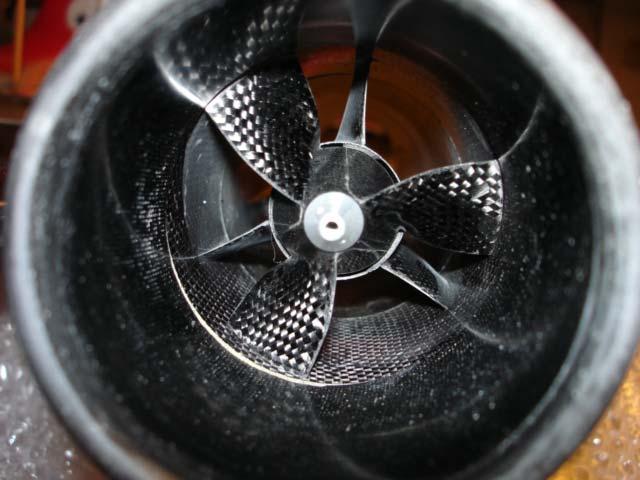
11 After you have prepared all air intakes as described, you can go ahead assembling the tubes and the EDFs as demonstrated on the following pictures: The tubes will be affixed on the EDF by using adhesive tape that is wrapped around the EDF and the pipe coupling. Page 12 of 20 EDF version 1.0


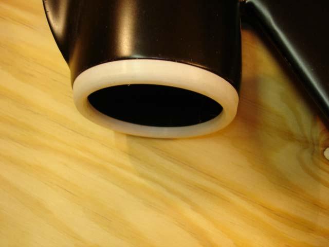
12 Now you can implement the EDF units in the gondolas. This should be done from the back of the model. When doing so, please pay attention not to deviate the cables. Even though the EDF units should fit closely, it should not be difficult to implement them. Adjust the inner diameter of the structure frames if necessary. The tubes should be overlapping in the front of the gondolas. It is important that the EDF units are mounted aligned in the gondolas. It should neither show angular distortion nor side trust. Now the intake rings should be affixed with Hysol or similar epoxy on the edge of the tubes and the front of the gondolas as shown on the next picture. Page 13 of 20 EDF version 1.0

13 At the outlet the tubes can be fixed with a 1 mm balsa layer. If necessary add a plywood layer in addition. After fixing the tubes in the gondolas like this glue it with Hysol or equivalent. Page 14 of 20 EDF version 1.0
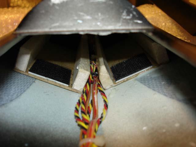
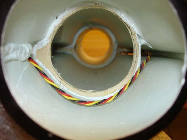
14 Installation of the battery The battery must be placed in the center of gravity (see page 19 of the manual). Ensure that they are not able to move during the flight (e.g. by fixing them with Velcro ). Page 15 of 20 EDF version 1.0

15 Suggestion for the installation of the interior equipment It is always a matter of individual preference on where to install the various electronic components, receiver, battery and so on. The pictures below show the installation we have used for our model. Page 16 of 20 EDF version 1.0

16 Page 17 of 20 EDF version 1.0


17 Page 18 of 20 EDF version 1.0

18 Page 19 of 20 EDF version 1.0

19 Center of gravity and throws The center of gravity is located 510 mm measured forward from the end of the fuselage. For stable flight quality we strongly recommend not to vary this default! Aileron deflection: inner ones + 30 mm; outer ones +15 mm 20 mm Elevator deflection: inner ones + 25 mm; outer ones +15 mm 20 mm Outer elevons: approx. 10 mm up Recommended accessories: Eurokit retract small 3 kg or EJF 3 gear air retract set low profile Main gear: WaBo struts SR-71 ; nose gear: Eurokit CAR/15082/000 INTAIRCO wheels and brakes No. IAC 1000 (diameter: 57 mm main and nose wheels) EDF: 2x Schübeler DS-30-Dia 3-ph Motor: 2x Hacker B40-13S Controller: 2x Hacker MASTER 40-O-flight Servos: HS 5125 MG or HS 125 MG (Elevon and Rudder) 2 x Mini servos (only if mechanically retract valve and brakes are used) air intakes: Wemotec 2x MF-R4 and 1x MF-R2 Spare parts: Rudder set Order No.: SR Elevon set (inner and outer ones) Order No.: SR Canopy Order No.: SR Air intakes Order No.: SR Frames set Order No.: SR Last update: March 2006 Page 20 of 20 EDF version 1.0
JTM 90mm EDF Viper Jet Installation Manual
 JTM 90mm EDF Viper Jet Installation Manual Provided by ERJets www.erjets.com 1 Disclaimer: Welcome onboard! This radio controlled jet is not a toy. It has the capability of flying in high speed and therefore
PITTS S2S CONSTRUCTION
 PITTS S2S CONSTRUCTION FUSELAGE CONSTRUCTION 1) Place the right fuselage side over the plan and mark the former positions. Place the left side over the right side and mark the former positions. Glue F1
FUSELAGE CONSTRUCTION
 FUSELAGE CONSTRUCTION Note: prior to building and gluing on the work surface use protective covering on your building surface. (wax paper or clear wrap) Fit the laser cut Fuselage Front and Fuselage Rear
Citabria Pro. Aerobatic Parkflyer. by Joel Dirnberger
 Citabria Pro Aerobatic Parkflyer by Joel Dirnberger Revision C: December 21, 2004 Citabria Pro Building Instructions Length: Wingspan: Wing Area: Flying Weight: Wing Loading: Functions: Specifications:
C-180 Builder s Manual
 C-180 Builder s Manual. May 20, 2002 Last revised July 11, 2002 Copyright! 2002 Douglas Binder, Mountain Models www.mountainmodels.com sales@mountainmodels.com (719) 630-3186 1 Required Equipment! Xacto
2COOL 2COOL.indd :24:34
 2COOL 2COOL.indd 1 17.9.2004 12:24:34 2COOL Dear customer, congratulations on the purchase of the 2Cool model. Before you begin, please read carefully the building instructions and make sure that you understand
High performance 90mm fiberglass jet
 High performance 90mm fiberglass jet Assembly manual For intermediate and advanced fliers only! Specs Wingspan: 1255mm Fuselage length: 1250mm Flying weight: 2600-3000g Wing area: 22.6 dm² Wing loading:
第 4 页, 共 17 页. 3. Epoxy the wood block to the servo tray base on the mark line. Accessory part lists for wing installation.
 第 1 页, 共 17 页 第 2 页, 共 17 页 第 3 页, 共 17 页 Accessory part lists for wing installation. 3. Epoxy the wood block to the servo tray base on the mark line. 1. Ready for assemble the wing servos. 4. Epoxy the
ParkJet Builder s Manual
 ParkJet Builder s Manual Thank you for purchasing the ParkJet. The ParkJet is a profile ducted fan airplane that can be flown in a larger park. The ParkJet was initially designed by Scott Stoops and modified
Edge 540 V3 35CC. Scheme A. Item No:L G Specifications. Flying Weight
 Edge 540 V3 35CC Item No:L G035016 Specifications Wing Span Length Wing Area Flying Weight Glow Gasoline Electric Radio Description 76 (1930mm) 74 (1879mm) 1200sq in(77.4sqdm) 9.9 12lbs(4.5 5.5kg) 91 1.20(2C)
Corvus Racer CC
 Corvus Racer 540 35CC Item No:L-G035008 Specifications Wing Span Length Wing Area Flying Weight Glow Gasoline Electric Radio mm mm 1200sq in (77.4sqdm) 9.9-12lbs(4.5-5.5kg) 91-1.20(2C) 1.10-1.40(4C) 20-40cc
HIGH-END TECHNOLOGY. Electric ducted fan rafale
 HIGH-END TECHNOLOGY RC Electric ducted fan rafale First we want to thank and congratulate you with your decision in buying one of our Kits. The Rafale puts together very easily so there is not much explanation
HIGH-END TECHNOLOGY. Electric ducted fan Starfighter
 HIGH-END TECHNOLOGY RC Electric ducted fan Starfighter First we want to thank and congratulate you with your decision in buying one of our Kits. The Starfighter puts together very easily so there is not
SZD-10 bis CZAPLA ASSEMBLY MANUAL IN PICTURES
 1 RUDDER Plan and parts: 2 Assembly steps: Photo above: glue together rudder spar, ribs and trailing edge. Clamp spar to a flat surface (chipboard on the photo) and make sure the straight aligment of the
RESolution V2 Manual
 RESolution V2 Manual Note for the German Manual: Yellow Bottle thick CA Pink Bottle Med CA Blue tube 5 minute Epoxy Green tube 90 Minute Epoxy Construction of the Fuselage Step 1: Cover the plan with a
BUILDING INSTRUCTION Allround fun glider PINO 3.0 E-Version. PINO 3.0 E Building Instruction August
 Wing span [mm]: 3000 Wing area [dm2]: 54,7 Aspect ratio: 16,6 Take-off weight [g]: from about 1830-2710g Wing loading: Airfoil: 31,6-47,5g/dm MP1-1,66/7,6 to MP5-1/5 5 Modern F3b-F3f airfoils BUILDING
F100 Super Sabre instructions.
 F100 Super Sabre instructions. The F100 is a Jet model for the Wemotec 480 Minifan. Start with taking the parts out of the sheet and sand of the connection tabs. Instructions RBCkits F100 Super Sabre 1
第 4 页. 3. Apply instand type AB glue to the holes in the aileron and hinges. Epoxy the aileron to the wing.
 TopRCModel-USA.com TopRCModel-USA.com TopRCModel-USA.com Accessory list for the installation of aileron and flap. 3. Apply instand type AB glue to the holes in the aileron and hinges. Epoxy the aileron
DRAFT COPY BUILDING INSTRUCTIONS FOR BLACKBURN BUCCANEER S2 VERSION 1 (BETA BUILD) BY MARK DOUGLAS
 BY MARK DOUGLAS") BUILDING INSTRUCTIONS FOR BLACKBURN BUCCANEER S2 VERSION 1 (BETA BUILD) BY MARK DOUGLAS COPYRIGHT MARK DOUGLAS 2011 THIS IS A "SHORT" KIT FOR EXPERIENCED BUILDERS AND FLYERS ONLY, DESIGNED BY A SHED DWELLING
BUILDING INSTRUCTIONS FOR BLACKBURN BUCCANEER S2 VERSION 1 (BETA BUILD) BY MARK DOUGLAS COPYRIGHT MARK DOUGLAS 2011 THIS IS A "SHORT" KIT FOR EXPERIENCED BUILDERS AND FLYERS ONLY, DESIGNED BY A SHED DWELLING
FLITZEBOGEN-2 Assembly instructions
 FLITZEBOGEN-2 Assembly instructions Trim the end of the fuselage to the length of 925mm from the nose. Be careful to avoid splitting the carbon fibers. Sand the base of the stab mount in preparation for
Preliminary pilot information
 Recommended RC-components: Preliminary pilot information RC-component suggestions for Freestyler 3, V-tail version FLAPS AILERONS V-tail receiver battery low-cost HS85 MG HS85 MG HS81 MG SMC 14 4 x AA
Hobby Lobby Zip Supplementary instructions Please refer to the included drawings while using these assembly instructions
 Materials needed: 15 or 30 minute epoxy Medium CA Masking tape Scotch tape Servo Tape Wax paper Tools Needed: Pencil or marker Flat building surface Hobby knife or razor blade 7/64" or 3mm drill bit 3/16"
MXS R 30CC. Item No:L G Specifications. 67 1/2"(1720mm) (2C) (4C) 26 35cc gas DLE 30/35RA MLD35 JC30Evo.
 (2C) (4C) 26 35cc gas DLE 30/35RA MLD35 JC30Evo.") MXS R 30CC Item No:L G030008 Specifications Wing Span Length Wing Area Flying Weight Glow Gasoline Electric Radio Description Covering Material Carbon Fibre : 75"(1915mm) 67 1/2"(1720mm) 1023sq in(66sq
MXS R 30CC Item No:L G030008 Specifications Wing Span Length Wing Area Flying Weight Glow Gasoline Electric Radio Description Covering Material Carbon Fibre : 75"(1915mm) 67 1/2"(1720mm) 1023sq in(66sq
The BIPE NX Assembly Manual
 The BIPE NX Assembly Manual Specifications Wing Span: 34 inches Wing Area: 550 in 2 Fuselage Length: 36 inches Weight (ready to fly): 20 to 24 oz. Wing Loading: 5.2 to 6.3 oz/ft 2 Designed by Jim Vigani
Cover the wing trailing edge and the aileron leading edge with strapping tape as shown.
 Cover the wing trailing edge and the aileron leading edge with strapping tape as shown. The aileron hinges are done using strapping tape on the top and bottom surfaces of the ailerons as shown. Make sure
E-AERO EPP PITTS KIT From BP HOBBIES. Parts Included in kit
 E-AERO EPP PITTS KIT From BP HOBBIES Parts Included in kit Thank you for purchasing the BP Hobbies/E-aero EPP Pitts. Please take the time to read through the instruction manual before beginning the build.
EXTRA 330SC 60CC. Item No:H G Specifications cc gas DA50,DA60, DLE55, DLE60(twin), 3W55. Description
, 3W55. Description") EXTRA 330SC 60CC Item No:H G060011 Specifications Wing Span Length Wing Area Flying Weight Gasoline Radio Description Carbon Fibre : 92" (2347mm) 84 1/2 " (2060mm) 1526.8 sq in(98.5sq dm) 16 17lbs(7300
EXTRA 330SC 60CC Item No:H G060011 Specifications Wing Span Length Wing Area Flying Weight Gasoline Radio Description Carbon Fibre : 92" (2347mm) 84 1/2 " (2060mm) 1526.8 sq in(98.5sq dm) 16 17lbs(7300
F3A -70E ASSEMBLY MANUAL
 F3A -70E ASSEMBLY MANUAL The new F3A-70E, was designed in an extremely lightweight structure, the all wood airframe, and the new revolutionary Lift Generator on landing gear give the F3A-70E an impressive
BUILDING INSTRUCTION Allround fun glider PINO 3.0. PINO 3.0 Building Instruction August
 Wing span [mm]: 3000 Wing area [dm2]: 54,7 Aspect ratio: 16,6 Take-off weight [g]: from about 1730-2610g Wing loading: Airfoil: 31,6-47,5g/dm MP1-1,66/7,6 to MP5-1/5 5 Modern F3b-F3f airfoils BUILDING
Sbach 1,2m 3D/aerobatic EPP model Building instructions
 Sbach 1,2m 3D/aerobatic EPP model Building instructions Please refer to the Diagram sheet Diagrams A, B Press 2 carbon strips (1x3x1000 mm) into the grooves in the sides of the fuselage central part (the
BUILDING INSTRUCTION Allround fun glider PINO electric version. PINO E - Building Instruction September
 Wing span [mm]: 2500 Wing area [dm2]: 44 Aspect ratio: 14 Take-off weight [g]: from 1400-2100g Wing loading: Airfoil: 32-48g/dm VS2/ VS3/ VS4/ VS5/ VS6 Modern F3b-F3f airfoils BUILDING INSTRUCTION Allround
1/6 PA-25 PAWNEE. *Specifications are subject to change without notice.*
 1/6 PA-25 PAWNEE INSTRUCTION MANUAL [ A335 Kit ] Wing Span : 72 in / 1830 mm Wing Area : 736 sq in / 47.5 sq dm Flying Weight : 6.6 lbs / 3000 g Fuselage Length : 48 in / 1220 mm Requires : "Glow Power"
Extra 330LT CC. 2 Colour schemes H-G120001A ORACOVER FERRARI RED # ORACOVER WITH # ORACOVER BLACK # ORACOVER SILVER #
 Extra 330LT 85-125CC Item No:A-G120001 Specs: WING SPAN: LENGTH: WING AREA: FLYING WEIGHT: ENGINE: RADIO: Description Covering Material Carbon Fibre: 111 (2833mm) 100" (2530mm) 2139sq in (138sq dm) 25.3-28lbs
MECOA EZ-4061 Trainer
 MECOA EZ-4061 Trainer EZ-4061 is a newly designed, Almost Ready to Fly kit. It is an extremely easy to control trainer with strong construction and excellent aerodynamic performance. This is a great choice
Stream NXT - assembly instructions
 Stream NXT - assembly instructions Recommended settings CG (measured from root leading edge): Speed/launch camber (+down, near the wing root): Cruise camber (+down, near the wing root): Thermal camber
BUILDING INSTRUCTION ERWIN XL ultralight. Erwin XL ultralight building Instruction August
 Wing span [mm]: 3000 Aspect ratio: 14,67 Wing area [dm2]: 61,33 Wing loading: from 19,6 Weight [g]: from 1200 Airfoil: VS1 BUILDING INSTRUCTION ERWIN XL ultralight www.pcm.at 1 CONTENTS DATA 1. Kit Contents
Switchback Sport Builder s Manual
 Switchback Sport Builder s Manual Thank you for purchasing the Switchback Sport. The Switchback Sport has been designed for the novice to intermediate pilot who wants a plane with good performance that
Parts Identification
 We are excited to introduce the Model Aero Aqua Sport. This is an excellent sport flyer, equally at home flying from grass fields, water, or even snow! The unique V-tail gives the Aqua Sport a distinctive
SebArt professional line
 SebArt professional line Wind S 110 ARF ASSEMBLY MANUAL The new Wind S 110 ARF was designed by Italy aerobatic pilot, Sebastiano Silvestri. This professional ARTF kit is the result of Sebastiano s 20 years
Instructions - Stobel V2
 Instructions - Stobel V2 Congratulations on the purchase of your Stobel, a high end DLG-competition model from LE-composites. We hope you will be happy and successful. To ensure the optimum build we ask
Print scale 5 inches
 www.mikeysrc.com FPV V3 Slow flying, stable plane for FPV. PDF NOTES and TIPS **PRINT ONLY THIS PAGE FIRST** to check that the printed scale is correct. The black line below should be five inches long.
BUILDING INSTRUCTION Allround fun glider PINO. PINO Building Instruction July
 Wing span [mm]: 2500 Wing area [dm2]: 44 Aspect ratio: 14 Take-off weight [g]: from 1500-2200g Wing loading: Airfoil: 34-50g/dm VS2/ VS3/ VS4/ VS5/ VS6 Modern F3b-F3f airfoils BUILDING INSTRUCTION Allround
Building Tips This model can be built using the following types of adhesives:
 Page 1 Building Tips This model can be built using the following types of adhesives: Epoxy (with or without microballons) Odorless cyanoacrylate (CA) with accelerator UHU Creativ for Styrofoam (or UHU
Venturi EVO 2 FPV. Thank you for purchasing the Venturi EVO FPV wing
 Thank you for purchasing the Venturi EVO FPV wing The Venturi FPV is designed for First Person Viewing (FPV) and for UAV/Drone experimentation. There is a power system for this model, see the website for
Cheeper Assembly instruction
 1. Equipment, materials and tools for assembly.......2 2. Assembly.....3 3. Setting of the model.....11 1. Equipment, materials and tools for assembly 1 Wing; 2 Fuselage; 3 Stabilizer; 4 Fin; 5 Dowel for
Skywalker X8 Installation Manual
 Skywalker X8 Installation Manual Thank you for Purchasing the Skywalker X8 FPV Plane from FPV Model. The Skywalker X8 is specially designed for First Person View (FPV) purpose. Technical Parameters Wingspan:
(Build Instructions)
") (Build Instructions) Specifications * Wingspan: 58cm * Length: 50cm * Flying Weight: 59 grams * Channels: 3 (Rudder Elevator Throttle) * Suggested Receiver: 4Ch Micro * Motor: 8mm GearDrive * Prop: GWS
(Build Instructions) Specifications * Wingspan: 58cm * Length: 50cm * Flying Weight: 59 grams * Channels: 3 (Rudder Elevator Throttle) * Suggested Receiver: 4Ch Micro * Motor: 8mm GearDrive * Prop: GWS
VIPER 140 Manual. Release 1.0 January 2018
 VIPER 140 Manual Release 1.0 January 2018 Please read this user manual carefully, it contains instructions for the correct assembly of the model. Please refer to the web site www.harlock-rc.com for updates
NASTY Build Guide. Supplies needed
 NASTY Build Guide Supplies needed Blucore or Depron Foam. Blucore (Fan Fold Foam) is available at Lowes. Approximately $25 for 50 feet of Blucore. Depron can be ordered on the internet for slightly more.
Admas A500. Specification:
 Admas A500 Specification: Length :07 mm(8.7") Wing Span :00 mm(9.5") Wing Area :8.8 sq. dm 5.5 sq. ft Wing Loading :3 g/sq. dm 53.7 oz/sq. ft Flying Weight :8 kg(7.lbs) Radio :ch &3 servos Engine : -cycle
Dandy Sport Builder s Manual
 Dandy Sport Builder s Manual Thank you for purchasing the Dandy Sport. The Dandy Sport has been designed as an easy to build aileron trainer. Take your time and enjoy building this plane. Specifications:
Skymaster ARF F-18E Instructions Manual
 Skymaster ARF F-18E Instructions Manual first: Take out the front servos mount, install front fuel tank before installing nose cone connect nose cone to fuselage by 6 screw Take out the 6 screws and Bottom
EPP Rebel Z 35. White Red w/ Blue Orange w/ Blue Orange w/burgundy Other. Specs. Color - Bottom White Black Checkers Silver Checkers Other Checkers
 EPP Rebel Z 35 Specs AUW ~10.0oz Width 35.28 Length 34.67 Wing Area 1.44 sqft Horz Area 2.35 sqft Vert Area.91 sqft
Magpie. Foam Trainer. Magpie Specifications
 Magpie Foam Trainer Magpie Specifications Length: 34in. Wingspan (SF): 46in. Wing Area (SF): 414in 2 Wingspan (SP): 40in. Wing Area (SP): 360in 2 Weight (without battery): 12oz. Thank you for purchasing
T-15 EDF INSTRUCTION MANUAL. Wingspan.31in. Weight..2.5 lb. EDF...70mm 12 Blade ToughJets, LLC Kittery, ME Page 1 of 22.
 TM T-15 EDF INSTRUCTION MANUAL Specifications Wingspan.31in Length..41.75in Wing Area 515 sq in EDF...70mm 12 Blade Weight..2.5 lb Radio...3 channel Motor...Brushless Battery 14.8v 2200mah 40c 2013 ToughJets,
Instruction Manual. Specification:
 Instruction Manual H I G Specification: Wingspan: 133 cm (52.3 inches) Length : 104 cm (40.9 inches) Weight : 1830gr Engine : 25-32 two stroke Radio : 4 channel - 4 servo H W I N G KIT CONTENTS: We have
INCLUDED IN THIS KIT: SPECIFICATION: NEEDED BUILDING TOOLS: REQUIRED EQUIPMENT:
 Please review this entire manual before beginning assembly. By doing so it will help you better understand each step as you progress in the actual building of your kit, and you will do a better job in
BUILDING INSTRUCTION ERWIN XL slope. Erwin XL slope building Instruction August
 Wing span [mm]: 3000 Aspect ratio: 14,67 Wing area [dm2]: 61,33 Wing loading: 49-70 Weight [g]: 3000-4500 Airfoil: VS1 BUILDING INSTRUCTION ERWIN XL slope www.pcm.at 1 CONTENTS DATA 1. Kit Contents 2.
Super Sky Surfer 2000 Assembly Instructions
 Super Sky Surfer 2000 Assembly Instructions Note: Plug and Play version of the Sky Surfer comes with fuselage pre-glued and motor/servos installed. If you wish to route antennas or wires through the tail,
F - 4u Corsair (50cc)
") F - u Corsair (50cc) Specification: Length: 73(.3") Wing span: 0mm(5") Wing area: 7.00sq.dm(9.39sq.ft) Wing loading: 35.g/sq.dm(.5oz/sq.ft) Flying weight:.kg(.0lbs) Radio: ch & 0servos Engine: 50cc gasoline
F - u Corsair (50cc) Specification: Length: 73(.3") Wing span: 0mm(5") Wing area: 7.00sq.dm(9.39sq.ft) Wing loading: 35.g/sq.dm(.5oz/sq.ft) Flying weight:.kg(.0lbs) Radio: ch & 0servos Engine: 50cc gasoline
GYM-E. Instruction Manual - Version 1.03
 GYM-E Original Design by Todd Long Instruction Manual - Version 1.03 Span 31 in. / Length 27 in. / Area 265 Sq. In. / Weight 4.5-6.5 oz. Gym-E kit reproduced with permission by Stevens AeroModel 2008 Stevens
Precut Wingola Kit Instructions
 Precut Wingola Kit Instructions Below is the precut option. Battery compartment, Receiver and Servo Trays are cut for mini radio gear. This is the uncut version. It has the placement laid out for the radio,
SNIPE 2 Recommendations for assembly
 Accessory kit: 1. The list of parts and materials to build: Parts set: 1 - Launching peg; 2 - Aileron clevises (with M2.5 thread); 3 - Stabilizer control horn; 4 - Rudder control horn; 5 - Set of screws
A high performance aerobatic model glider for slope soaring, Designed by James D Hammond and brought to you by Sloperacer.
 Aresti 2m instructions page 1 A high performance aerobatic model glider for slope soaring, Designed by James D Hammond and brought to you by Sloperacer. Thank you for purchasing the Aresti 2m. The design
F-16 Falcon 70mm EDF
 F-16 Falcon 70mm EDF Instruction manual Specifications: Winspan: 640 mm Length: 990 mm Weight: 900-1100 gram Ducted fans 70mm x 1 Required tools and components:. 4 ch. Computer Radio system w/ 2 servos.
Fokker Dr1 Master Instructions
 Fokker Dr1 Master Instructions Rev 1 Congratulations on your new project. This Dr1 kit is the finest to date. The construction of the plane is similar and exactly like the original. Take your time and
BUILDING INSTRUCTION ERWIN. Erwin building instruction September
 Technical data: Wing span [mm]: 2045 Weight [g]: 1300-1600 Wing loading [g/dm 2 ]: 44,0-54,2 Airfoill: HQW/1,5/7mod-gestrakt Aspect ratio: 13,54 Controls: H/S/Q/W Construction: Fuselage CFR/GFR strengthened
LANDING GEAR. 1. Fit landing gear into slots on bottom of fuselage.
 LANDING GEAR 1. Fit landing gear into slots on bottom of fuselage. 4. Use channel-lock pliers to press blind nuts into position (note: drilled hole should be slightly smaller than shaft of blind nut for
Specifications. Before commencing assembly, please read these instructions thoroughly.
 INSTRUCTION MANUAL Before commencing assembly, please read these instructions thoroughly. Specifications Wing Span: 8.5 in / 30 mm Wing Area: 330 sq in /.3 sq dm Flying Weight: 6 oz / 70 g Fuselage Length:
Designed in 2005 by Bernard Burton. Assembly manual Bernard Burton DRAFT 1
 Designed in 2005 by Bernard Burton Assembly manual 2005 - Bernard Burton DRAFT 1 The plans can be requested via this link http://www.gundersonaerodesign.com/m12plansreq.htm The laser kit is available here
Parkflyer F6F Hellcat
 Parkflyer F6F Hellcat Page 1 of 19 MOLT MODELS Background Design Philosophy When I was first introduced to this hobby seventeen years ago I saw my first WWII warbird and I was hooked. Several years later
Construction on this ship came to
 On the Wing... Redwing XC, Part 4 Fuselage components, vertical fin and rudder Bill & Bunny Kuhlman, bsquared@themacisp.net Construction on this ship came to a near standstill for a couple of months, but
Ryan STA Sport Scale Model Aircraft Assembly and Instruction Manual
 Ryan STA Sport Scale Model Aircraft Assembly and Instruction Manual Warning: This radio controlled model is not a toy. It requires skill to fly and is not recommended for the novice pilot. It should not
105" TIGER MOTH ARF INSTRUCTION MANUAL VERSION 1.0
 105" TIGER MOTH ARF INSTRUCTION MANUAL VERSION 1.0 Step 1. Installation of the aileron servos 1) Mount aileron servo to servo mounting blocks with servo s screws. Install servo mounting plate with screws.
Pilatus PC-9 INSTRUCTION MANUAL SAFETY PRECAUTIONS. Specification:
 Pilatus PC-9 Specification: Length: Wing span: Wing area: Wing loading: Flying weight: Radio: Engine: 9mm(7 ) 0mm(0 ) sq.dm(.9sq.ft) 0.g/sq.dm(.9oz/sq.ft).kg(7.bs) ch & servos 0 -cycle 0cc gasoline engine
SAAB JAS 39 Gripen. Building Instructions Designed by: Steve Shumate. Taken From:
 SAAB JAS 39 Gripen Building Instructions Designed by: Steve Shumate Taken From: http://www.rcgroups.com/forums/showthread.php?t=308830&page=1 Lightly tack glue the paper templates to the foam sheets using
ARF Manual Elevator assembly Wings assembly Landing Gear Mid section wing Front Retract assembly Midsection to fuselage
 Easyjet ARF Manual 1. Elevator assembly 2. Wings assembly 3. Landing Gear 4. Mid section wing 5. Front Retract assembly 6. Midsection to fuselage 7. Engine / Electrical (under contruction) 8. Fuel system
BUILDING INSTRUCTION ERWIN. Erwin building instruction November
 Tecnical data: Wing span [mm]: 2000 Weight [g]: 1100-1600 Wing loading [g/dm 2 ]: 37,3-54,2 Airfoill: HQW/1,5/7mod-gestrakt Aspect ratio: 13,54 Controls: H/S/Q/W Construction: Fuselage CFR/GFR strengthened
PURE PLEASURE for YOU
 1 GRAPHITE 2. Assembling gide PURE PLEASURE for YOU Technical support: VLADIMIR'S Model http://airplane-model.com e-mail: order@airplane-model.com Technical data: Wing span: 3100 mm Wing area: 64.5 dm
Corvus Racer Colour schemes. AeroPlus RC Copyright 2013 All Rights Reserved
 Corvus Racer 540 59 Item No:A E050003 Specifications WING SPAN: 59"(1500mm) LENGTH: 54.1"(1374mm) WING AREA: 654sq.in.(42.2sq.dm.) FLYING WEIGHT: 4.6 5.3lbs(2000 2300g) Electric:Brushless outrunner 8Oz.
Thank you for your purchase of the Lee Ulinger, FoamtanaS, Yak-55, or Extra 330 3D Depron foam, Aerobatic airplane.
 Thank you for your purchase of the Lee Ulinger, FoamtanaS, Yak-55, or Extra 330 3D Depron foam, Aerobatic airplane. Tools you will need to build Recommended additional items: #11 hobby knife Motor: Hacker
BUILDING INSTRUCTION F5J Electro-thermic-glider TASER. Taser Building instruction November
 Wingspan [mm]: 2000 Takeoff weight [g]: 450-580 Airfoil: AG 455ct-02f AG47ct-02f by Mark Drela BUILDING INSTRUCTION F5J Electro-thermic-glider TASER www.pcm.at 1 CONTENTS DATA 1. Kit contents 2. What else
6mmFlyRC.com Super Bandit Assembly Instructions
 Assembly Instructions Start the assembly with forward fuselage. Lay the two fuselage sides down on a flat surface and glue the foam corner doublers to the locations shown on the plans. Make sure to make
BOOMERANG TORUS. Aerobatic Sport Jet for 20 to 34 lbs (P80 to P160) thrust turbines.
 thrust turbines.") BOOMERANG TORUS Aerobatic Sport Jet for 20 to 3 lbs (P80 to P160) thrust turbines. Specifications: Span... 83" (2209mm.) Span with Wingtip Tanks 90" (2286mm.) Length...87" (2108mm.) Weight 29 Lbs.(13.15
BOOMERANG TORUS Aerobatic Sport Jet for 20 to 3 lbs (P80 to P160) thrust turbines. Specifications: Span... 83" (2209mm.) Span with Wingtip Tanks 90" (2286mm.) Length...87" (2108mm.) Weight 29 Lbs.(13.15
Eva. Extremely Versatile Airframe
 Eva Extremely Versatile Airframe Eva Specifications Length: 32 Weight (without battery): ~12oz. Revision History Date Revision Notes/Comments 6/3/05 Document initial creation. Thank you for purchasing
Hawker hurricane MK.IIa
 Hawker hurricane MK.IIa Specification: Length :00 mm(") Wing Span :00 mm(") Wing Area :0. sq. dm.9 sq. ft Wing Loading :.9 g/sq. dm 5.9 oz/sq. ft Flying Weight :.kg(5 lbs) Radio :ch& servos Engine :0 INSTRUCTION
28in Super EVA Foam. F-22 Raptor Kit. Specifications. Wingspan: 27.5in (700mm) Length: 38.3in (975mm) Flying Weight: Approx. 1.
 Length: 38.3in (975mm) Flying Weight: Approx. 1.") 28in Super EVA Foam F-22 Raptor Kit Specifications Wingspan: 27.5in (700mm) Length: 38.3in (975mm) Flying Weight: Approx. 1.2lbs (530g) Dear Customer, Congratulations on your purchase of 28in F22 Raptor
28in Super EVA Foam F-22 Raptor Kit Specifications Wingspan: 27.5in (700mm) Length: 38.3in (975mm) Flying Weight: Approx. 1.2lbs (530g) Dear Customer, Congratulations on your purchase of 28in F22 Raptor
SPUNKY ASSEMBLY MANUAL
 SPUNKY ASSEMBLY MANUAL Please read the tips section at the back of this manual regarding the use of laser cut parts. The proper removal and preparation of these parts is important. When laser cut, some
BUILDING INSTRUCTION ERWIN XL. Erwin XL building Instruction September
 Wing span [mm]: 3000 Aspect ratio: 14,67 Wing area [dm2]: 61,33 Wing loading: 42,4-66,8 Weight [g]: 2800-4300 Airfoil: VS1 BUILDING INSTRUCTION ERWIN XL www.pcm.at 1 CONTENTS DATA 1. Kit Contents 2. What
Stearman PT-17 KIT WARRANTY
 Stearman PT-17 KIT # K-306 Assembly Instructions Version 2 02-17-16 Designed by Tom Herr WARRANTY Sig Manufacturing Co, Inc. guarantees this kit to be free from defects in both material and workmanship
Zeon PDF Driver Trial
 Mach Dart Slope Soarer Congratulations on your purchase of the Mach Dart Glider. This aircraft was crafted utilizing the latest technology in composite model aircraft design and manufacture. The Dart is
P-47D Thunderbolt. Two wheel retract system Make sure to assemble retracts as instructed below. 3-way pressure inlet INSTRUCTION MANUAL
 70 Adjustment. 7 The centre of the Gravity. Side View AILERON FLAP 0mm 0mm P-7D Thunderbolt AILERON FLAP 0mm 3mm Two wheel retract system Make sure to assemble retracts as instructed below. 3-way pressure
Spitfire Mk.IX ARF. Electric retract system. TopRCModel-USA.com
 Electric retract system Thank you very much for purchasing our TRCM optional electric retract set, all our products were passed strict QC before they shipped out to the customers. In order to avoid probably
AT channel 6 servos
 Wing Span: Wing Area: Fuselage Length: Flying weight: Power system: Radio: 60.7in/1540mm 561 sq in/36.3 sq dm 44.1in/1120mm 6.9 Ibs/ 3100g 46(2C0/71(4C) 5 channel 6 servos AT6-46 INSTALLING AILERONS Begin
F - 4u Corsair INSTRUCTION MANUAL SAFETY PRECAUTIONS. Two wheel retract system. Specification:
 Adjustment. 3 The centre of the Gravity. Never fly before checking CG s required position. In order to obtain the CG specified reposition the receiver and battery. ELEVATOR Top view F - u Corsair 0mm 0mm
Cirrus. Special Features: RC function: Dear friends, Thank you for purchasing our F5J competition high performance electric-powered glider Cirrus.
 1 Cirrus Dear friends, Thank you for purchasing our F5J competition high performance electric-powered glider Cirrus. Cirrus is made from slected special light balsa wood. Special Features: Carbon fuselage
Taylorcraft Indoor / Cul-De-Sac Flyer
 Taylorcraft Indoor / Cul-De-Sac Flyer Taylocraft Specifications Wingspan: 28.0 in. Wing Area: 117 sq. in. Weight (Ready to Fly): 3.0 3.1 oz. Wing Loading: 3.7 3.8 oz. / sq. ft. LIABILITY RELEASE In that
COMET SENIOR DART REPRODUCTION ASSEMBLY GUIDE
 COMET SENIOR DART REPRODUCTION A RUBBER POWERED 24" WING SPAN MODEL BY PAUL BRADLEY ASSEMBLY GUIDE JANUARY 2018 CHANGES MADE TO THE ORIGINAL The following changes were made to the original Comet kit structural
B-25 Mitchell INSTRUCTION MANUAL SAFETY PRECAUTIONS
 B-5 Mitchell Specification: Length :935 mm(76.") Wing Span :0 mm(95") Wing Area :77.6 sq. dm 7./sq.ft Wing Loading : g/sq. dm oz/sq. ft Flying Weight :0 kg(. lbs) Radio :6ch&3 servos Engine(a pair) :9
Spacewalker Instruction Read these instructions carefully before use. Please keep these instruction after assembling.
 Spacewalker Instruction Read these instructions carefully before use. Please keep these instruction after assembling. Ord. No. 00 6137! Safety precautions This radio control model is not a toy! Not suitable