PRESENTATION OF THE PROJECTX-FINAL LEVEL 1.
|
|
|
- Horatio Smith
- 5 years ago
- Views:
Transcription
1 Implementation of digital it frequency dividersid PRESENTATION OF THE PROJECTX-FINAL LEVEL 1.
2 Why frequency divider? Motivation widely used in daily life Time counting (electronic clocks, traffic lights, ) Events counting (counting parts on a conveyor, number of cars in self-parking area, ) Digital equipments for laboratory usage (signal generators, frequency meters, ) Computers, Video Systems, Electronic Advertising Boards, sequential logic circuits are not well represented in the curriculum and are not well assimilated/understood by students; To understand frequency dividers students must understand counters, to understand counters students must understand flip-flops, => they understand a lot of sequential circuits Frequency divider => Counters => Flip-Flops => A lot of sequential circuits must be understanding
3 What the student is going to do Project presentation This project has two parts: A. Theoretical Part Understand flip-flops and counters; Understand how to use counters as frequency dividers; B. Practical Part use dedicated di d computer programs to simulate counters and different types of frequency dividers; use breadboard and general purpose logic integrated circuits to implement and test any counter or frequency divider; use state of the art logic integrated circuits (reconfigurable circuits like CPLD or FPGA), to implement and test any counter or frequency divider;; improve their skills in handling laboratory equipment.
4 A. Theoretical Part
5 Understand flip flops A. Theoretical Part What is flip-flop, where we use? Types of flip-flops (D, T, JK) symbols, truth tables, functional equations; Flip-flop operation in synchronous mode; Flip-flop operation in asynchronous mode (important role of asynchronous inputs Clear and Preset ); Simple exercises with flip flops ( ); We are not focused on internal structures of the flip-flops!
6 Understand counters A. Theoretical Part What is a counter, where we use? Classification of counters after numeration system after counting directions after internal structures Special functions (other then counting) Terminal Count Parallel l Load Count Enable Representative (commercial) IC Counters Chips asynchronous counters (74LS93, 74LS90) synchronous counters (74LS192, 74LS193) We are not focused on internal structures of counters!


7 Design simple counters A. Theoretical Part 4-Bit Asynchronous counter made with JK Flip-Flops Counters Cascading Technique
8 What is a Frequency divider? A. Theoretical Part Frequency divider is a electronic circuit that: takes an input signal of a frequency f_in generates an output signal of a frequency f_out where K is an integer that is referred as division factor Frequency dividers are wildly used in modern electronic systems; Digital frequency dividers can be implemented with: Counters; Shift registers; Other circuits;
9 Types of Frequency dividers? A. Theoretical Part Frequency divider can have: Fixed division factor K and fixed duty-cycle ; (Usually made with asynchronous counters) Programmable division factor K and fixed duty-cycle ; (Usually made with synchronous counters) Programmable division factor K and programmable duty-cycle ; (Usually made with synchronous counters and (Usually made with synchronous counters and other supplementary logical circuits)
10 A. Theoretical Part Frequency divider with fixed K and fixed Example 1: Design process for frequency divider with K=12


 is memorized")

; Because of")

11 A. Theoretical Part Frequency divider with Programmable K and fixed Example 2: Frequency divider with K=74 using two BCD counters Desired factor is translated in BCD code 74= For data inputs of units (U1) we put 4-1=0011; For data inputs of tens (U2) we put 7=0111; Borrow signal (TCD for U2) is memorized by latch and then is used to drive the load inputs (PE); Because of latch => obtained K is greater by one then programmed K!
12 B. Theoretical Knowledge Divider with Programmable K and Programmable In previous two examples: Output signal is the same with load signal; Output signal has short Low state; Duration of each logic state can not be controlled; We can control (change) only frequency division factor; In order to get access to K and, we have to improve the schematic; Main idea: Use division factor K=M for LOW state; Use different division factor K=N for HIGH state; P ll l l d d l i l h h Parallel load M and N alternatively when counter reach zero state;


13 B. Theoretical Knowledge Divider with Programmable K and Programmable Example 3
14 B. Practical Part
15 Brief description of the Practice B. Practice 1. simulate counters and frequency dividers using TINA software (or similar); 2. implement and test counters and frequency dividers on breadboard with general purpose logic IC; 3. implement and test simple counters and frequency dividers in modern digital circuits such as CPLD or FPGA; 4. Use oscilloscope to verifying different types of frequency dividers (input/output signal visualization, input/output frequency determination, input/output t t voltage levels l of each logic state) t
16 1.Simulating digital circuits (1/2) C. Practice We suggest TINA Design Suite due to the following features: - analyzing, designing, and real time testing of analog, digital, HDL, MCU, and mixed electronic circuits and their PCB layouts; - circuits are entered as schematics with an easy-to-use schematic editor; - interactive simulation: great facility for digital circuits; - powerful virtual instruments: Digital Multimeter, Digital Signal Generator, Storage Oscilloscope, Function Generator, Logic Analyzer, Signal Analyzer; - Great support from Texas Instruments; - Student Edition is free, Basic Edition is around 130EUR; We propose simulations for well chosen schematics with: - flip flops; - Binary/Decimal counters in connections with other circuits to facilitate t state t visualization of the counters; counters connected for increase the maximal number of states; - Different types of frequency dividers;


17 1.Simulating digital circuits (2/2) C. Practice


18 2. Implement circuits using breadboard C. Practice Implement and test the functionality of the divider on breadboard, using general purpose logic IC (such as 74LS93, 74LS192, )
19 3. Implement circuits using FPGA (1/6) What is FPGA? C. Practice Actual trend in the implementation of digital systems is to use reconfigurable circuits like FPGA You can configure these chips to implement custom hardware functionality without ever having to pick up a breadboard or soldering iron Advantage of FPGA (Field-Programmable Gate Array) Large number of digital circuits which can be interconnected by the end user by software means (using a configuration bitstream); Bitstream contains information on how the components should be wired together to Completely reconfigurable - instantly take on a brand new personality when you recompile a different configuration of circuitry (a new bitstream); Easy to use mature high-level design tools are available; Low cost do to the mass production;
20 3. Implement circuits using FPGA (2/6) C. Practice Design steps when working with FPGA use a computer to describe a "logic function" that you want: - draw a schematic; - create a text file describing the function (using hardware description language like VHDL or Verilog). compile the "logic function" on your computer, using a software provided by the FPGA vendor. After this step we obtain a binary file (bitstream) that can be downloaded into the FPGA. circuit configuration - connect a cable from your computer to the FPGA, and download the binary file to the FPGA; test your applications according to your specifications. in case of mistake in design, just fix your "logic function", recompile and re-download it. We can make downloads in FPGAs as many time as we need (almost no limit), it) with different functionalities every time we want.
21 3. Implement circuits using FPGA (3/6) C. Practice Why we insist on teaching FPGA? Student Perspective: - students have the feeling that they working in software; - easy to develop and test new application (even without learn a hardware description language like Verilog or VHDL); - increased chances of finding a god job; Technical advantage: - Easy to use: You can configure these chips to implement custom hardware functionality without ever having to pick up a breadboard or soldering iron ; - Large number of digital it circuits it which h can be interconnected t by the end user by software means - Completely reconfigurable: in case of mistake in design, just fix your "logic function", re-compile and re-download d it. - Low cost do to the mass production;
22 3. Implement circuits using FPGA (4/6) C. Practice We suggest: - FPGA: Spartan 3E from Xilinx - Free Software: ISEWebPack - Board: Basys 2 (69$ in academic program)
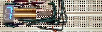
23 3. Implement circuits using FPGA (5/6) C. Practice Practical aspects: - Working with FPGA is not an easy task for beginners; - To make things easier, in each practical application, you will: - begin with one Template Project in which there are already implemented some circuits that are necessary for testing different diagrams with counters or frequency dividers Signal generator to provide the clock signal for counting under test. HexDisplay to display the state of the counter, in numeric format, on one of the four digits of the Basys2 board. BinDisplay to display the state of the counter, in binary format, using the last four LEDs of the Basys2 board. - use only schematic descriptions i of the logic circuits; i


 C.")


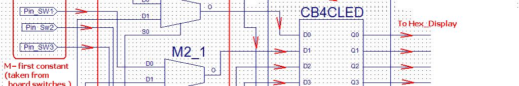


24 3. Implement circuits using FPGA (6/6) C. Practice Example: Programmable Frequency divider implementation in FPGA
25 C. Learning Outcomes
26 Learning Outcome1 C. Final Conclusions & Final Evaluation Using computer-based simulation software and technique to design electronics systems (TOPMOST: ELIDS10); Knowledge: Skills: Competences: - Understand the advantage and disadvantage of circuits simulations; - Know how to convert an generic logic diagram into an implementable electrical diagrams using commercial logic IC. Skills for circuit simulation: - draw the electrical diagram; - choose the right type of analysis; - display electrical signals in different points of electrical diagram; - Use virtual instruments. Skills for circuit design: - understand initial technical specifications; - design the logic diagram; - convert the logic diagram into electric schematic; choose the right logic ICs, - make right allocation of internal resources of the IC to cover all components of the logic diagram; - make right ihtconnections for unused IC pins; - Simulate electronic circuits using dedicated computer programs. - Design electronic circuits using dedicated computer programs.
27 C. Final Conclusions & Final Evaluation Learning Outcome 2 Build, test and check performance of basic sequential logic circuits; Knowledge: Skills: Competences: Use Data Sheet of logic circuit Skills for build the project: - Build simple and medium - make a bill of materials; complexity circuits with general - identify the ICs needed to construct the schematic; use logic integrated circuits; - make connection between pins; - Test simple and medium Skill for test the project: complexity circuits with general - check the correct realization of the electrical use logic integrated circuits; diagram; - make right connection to signal generator and power supply; - use oscilloscope to display the input/output electrical signals.
28 C. Final Conclusions & Final Evaluation Learning Outcome 3 Implementation of logic circuits in modern logic circuits like CPLD or FPGA; Knowledge: Skills: Competences: - understand concept of reconfigurable device; - understand the advantage of reconfigurable device. Skill for design the circuits: -make new project, add new sources into project, draw the schematic of the divider; -make constrains file (specify the input/output FPGA pins); - generate configuration file; Skill for implement and test the circuits: -download d l dthe configuration i file into FPGA; -make connection to the signal generator and power supply; -make tests to verify the functionality of the circuit. - Use one dedicated software environment to implement logic circuits in FPGA; - Implement and test simple and medium logic circuit in CPLD/FPGA devices.
29 C. Final Conclusions & Final Evaluation Learning Outcome 4 Design frequency dividers; Knowledge: Skills: Competences: - deep understanding of how electronic counters works; - practicalapplications applications of the counters; - standard methodologies for design frequency dividers; - where to use an frequency divider; - understand the technical specification; - choose the rightmethod to design the logic diagram of the divider; - convert the logic diagram into an realizable electrical diagram; Design frequency dividers with different specifications.
30 C. Final Conclusions & Final Evaluation Learning Outcome 5 Use oscilloscope to verifying and testing a electronic circuits; Knowledge: Skills: Competences: Understand where and how to use oscilloscope. - make connection between grounds of power supply, FPGA board and oscilloscope; - use one channel to view the input signal and other channel to view the output signal; - make correct adjustment for time base, inputs attenuators, synchronization. Proper use of laboratory equipments.
31 Thanks for your attention!
Digital Logic ircuits Circuits Fundamentals I Fundamentals I
 Digital Logic Circuits Fundamentals I Fundamentals I 1 Digital and Analog Quantities Electronic circuits can be divided into two categories. Digital Electronics : deals with discrete values (= sampled
Laboratory for the Introductory Digital Course
 Laboratory for the Introductory Digital Course Otto Fucik, Penn State University at Erie Bodgan Wilamowski, University of Wyoming Michael McKenna, University of Wyoming Abstract This lab entails practical
Digital Systems Design
 Digital Systems Design Digital Systems Design and Test Dr. D. J. Jackson Lecture 1-1 Introduction Traditional digital design Manual process of designing and capturing circuits Schematic entry System-level
Lab #10: Finite State Machine Design
 Lab #10: Finite State Machine Design Zack Mattis Lab: 3/2/17 Report: 3/14/17 Partner: Brendan Schuster Purpose In this lab, a finite state machine was designed and fully implemented onto a protoboard utilizing
FPGA Based System Design
 FPGA Based System Design Reference Wayne Wolf, FPGA-Based System Design Pearson Education, 2004 Why VLSI? Integration improves the design: higher speed; lower power; physically smaller. Integration reduces
CHAPTER III THE FPGA IMPLEMENTATION OF PULSE WIDTH MODULATION
 34 CHAPTER III THE FPGA IMPLEMENTATION OF PULSE WIDTH MODULATION 3.1 Introduction A number of PWM schemes are used to obtain variable voltage and frequency supply. The Pulse width of PWM pulsevaries with
EE19D Digital Electronics. Lecture 1: General Introduction
 EE19D Digital Electronics Lecture 1: General Introduction 1 What are we going to discuss? Some Definitions Digital and Analog Quantities Binary Digits, Logic Levels and Digital Waveforms Introduction to
PE713 FPGA Based System Design
 PE713 FPGA Based System Design Why VLSI? Dept. of EEE, Amrita School of Engineering Why ICs? Dept. of EEE, Amrita School of Engineering IC Classification ANALOG (OR LINEAR) ICs produce, amplify, or respond
Digital Electronic Concepts
 Western Technical College 10662137 Digital Electronic Concepts Course Outcome Summary Course Information Description Career Cluster Instructional Level Total Credits 4.00 Total Hours 108.00 This course
Instructional Demos, In-Class Projects, & Hands-On Homework: Active Learning for Electrical Engineering using the Analog Discovery
 Instructional Demos, In-Class Projects, & Hands-On Homework: Active Learning for Electrical Engineering using the Analog Discovery by Dr. Gregory J. Mazzaro Dr. Ronald J. Hayne THE CITADEL, THE MILITARY
Digital Fundamentals. Introductory Digital Concepts
 Digital Fundamentals Introductory Digital Concepts Objectives Explain the basic differences between digital and analog quantities Show how voltage levels are used to represent digital quantities Describe
Exercise 1: AND/NAND Logic Functions
 Exercise 1: AND/NAND Logic Functions EXERCISE OBJECTIVE When you have completed this exercise, you will be able to determine the operation of an AND and a NAND logic gate. You will verify your results
BEE 2233 Digital Electronics. Chapter 1: Introduction
 BEE 2233 Digital Electronics Chapter 1: Introduction Learning Outcomes Understand the basic concept of digital and analog quantities. Differentiate the digital and analog systems. Compare the advantages
ECE380 Digital Logic
 ECE380 Digital Logic Implementation Technology: Standard Chips and Programmable Logic Devices Dr. D. J. Jackson Lecture 10-1 Standard chips A number of chips, each with a few logic gates, are commonly
Exercise 2: OR/NOR Logic Functions
 Exercise 2: OR/NOR Logic Functions EXERCISE OBJECTIVE When you have completed this exercise, you will be able to determine the operation of an OR and a NOR logic gate. You will verify your results by generating
Basic Logic Circuits
 Basic Logic Circuits Required knowledge Measurement of static characteristics of nonlinear circuits. Measurement of current consumption. Measurement of dynamic properties of electrical circuits. Definitions
Lecture 3, Handouts Page 1. Introduction. EECE 353: Digital Systems Design Lecture 3: Digital Design Flows, Simulation Techniques.
 Introduction EECE 353: Digital Systems Design Lecture 3: Digital Design Flows, Techniques Cristian Grecu grecuc@ece.ubc.ca Course web site: http://courses.ece.ubc.ca/353/ What have you learned so far?
V-LAB COMPUTER INTERFACED TRAINING SET
 is an important tool for Vocational Education with it s built-in measurement units and signal generators that are interfaced with computer for control and measurement. is a device for real-time measurement
DIGITAL INTEGRATED CIRCUITS A DESIGN PERSPECTIVE 2 N D E D I T I O N
 DIGITAL INTEGRATED CIRCUITS A DESIGN PERSPECTIVE 2 N D E D I T I O N Jan M. Rabaey, Anantha Chandrakasan, and Borivoje Nikolic CONTENTS PART I: THE FABRICS Chapter 1: Introduction (32 pages) 1.1 A Historical
CMOS Digital Logic Design with Verilog. Chapter1 Digital IC Design &Technology
 CMOS Digital Logic Design with Verilog Chapter1 Digital IC Design &Technology Chapter Overview: In this chapter we study the concept of digital hardware design & technology. This chapter deals the standard
Digital Electronics. A. I can list five basic safety rules for electronics. B. I can properly display large and small numbers in proper notation,
 St. Michael Albertville High School Teacher: Scott Danielson September 2016 Content Skills Learning Targets Standards Assessment Resources & Technology CEQ: WHAT MAKES DIGITAL ELECTRONICS SO IMPORTANT
CONTENTS Sl. No. Experiment Page No
 CONTENTS Sl. No. Experiment Page No 1a Given a 4-variable logic expression, simplify it using Entered Variable Map and realize the simplified logic expression using 8:1 multiplexer IC. 2a 3a 4a 5a 6a 1b
SRV ENGINEERING COLLEGE SEMBODAI RUKMANI VARATHARAJAN ENGINEERING COLLEGE SEMBODAI
 SEMBODAI RUKMANI VARATHARAJAN ENGINEERING COLLEGE SEMBODAI 6489 (Approved By AICTE,Newdelhi Affiliated To ANNA UNIVERSITY::Chennai) CS 62 DIGITAL ELECTRONICS LAB (REGULATION-23) LAB MANUAL DEPARTMENT OF
Single Chip FPGA Based Realization of Arbitrary Waveform Generator using Rademacher and Walsh Functions
 IEEE ICET 26 2 nd International Conference on Emerging Technologies Peshawar, Pakistan 3-4 November 26 Single Chip FPGA Based Realization of Arbitrary Waveform Generator using Rademacher and Walsh Functions
Sampling. A Simple Technique to Visualize Sampling. Nyquist s Theorem and Sampling
 Sampling Nyquist s Theorem and Sampling A Simple Technique to Visualize Sampling Before we look at SDR and its various implementations in embedded systems, we ll review a theorem fundamental to sampled
DIGITAL SYSTEM DESIGN WITH VHDL AND FPGA CONTROLLER BASED PULSE WIDTH MODULATION
 DIGITAL SYSTEM DESIGN WITH VHDL AND FPGA CONTROLLER BASED PULSE WIDTH MODULATION Muzakkir Mas ud Adamu Depertment of Computer Engineering, Hussaini Adamu Federal Polytechnic Kazaure, Jigawa State Nigeria.
Project Board Game Counter: Digital
 Project 1.3.3 Board Game Counter: Digital Introduction Just a few short weeks ago, most of you knew little or nothing about digital electronics. Now you are about to build and simulate a complete design.
logic system Outputs The addition of feedback means that the state of the circuit may change with time; it is sequential. logic system Outputs
 Sequential Logic The combinational logic circuits we ve looked at so far, whether they be simple gates or more complex circuits have clearly separated inputs and outputs. A change in the input produces
Academic Course Description
 BEC010- VLSI Design Academic Course Description BHARATH UNIVERSITY Faculty of Engineering and Technology Department of Electronics and Communication Engineering BEC010 VLSI Design Sixth Semester (Elective)
Academic Course Description
 BEC010- VLSI Design Academic Course Description BHARATH UNIVERSITY Faculty of Engineering and Technology Department of Electronics and Communication Engineering BEC010 VLSI Design Fifth Semester (Elective)
CS302 - Digital Logic Design Glossary By
 CS302 - Digital Logic Design Glossary By ABEL : Advanced Boolean Expression Language; a software compiler language for SPLD programming; a type of hardware description language (HDL) Adder : A digital
Entry Level Assessment Blueprint Electronics Technology
 Blueprint Test Code: 4135 / Version: 01 Specific Competencies and Skills Tested in this Assessment: Safety Practices Demonstrate safe working procedures Explain the purpose of OSHA and how it promotes
LOGIC DIAGRAM: HALF ADDER TRUTH TABLE: A B CARRY SUM. 2012/ODD/III/ECE/DE/LM Page No. 1
 LOGIC DIAGRAM: HALF ADDER TRUTH TABLE: A B CARRY SUM K-Map for SUM: K-Map for CARRY: SUM = A B + AB CARRY = AB 22/ODD/III/ECE/DE/LM Page No. EXPT NO: DATE : DESIGN OF ADDER AND SUBTRACTOR AIM: To design
CHAPTER 16 SEQUENTIAL CIRCUIT DESIGN. Click the mouse to move to the next page. Use the ESC key to exit this chapter.
 CHPTER 6 SEQUENTIL CIRCUIT DESIGN Click the mouse to move to the next page. Use the ESC key to exit this chapter. Contents 6. Summary of Design Procedure for Sequential Circuits 6.2 Design ExampleCode
Course Outcome of M.Tech (VLSI Design)
") Course Outcome of M.Tech (VLSI Design) PVL108: Device Physics and Technology The students are able to: 1. Understand the basic physics of semiconductor devices and the basics theory of PN junction. 2.
Course Outcome of M.Tech (VLSI Design) PVL108: Device Physics and Technology The students are able to: 1. Understand the basic physics of semiconductor devices and the basics theory of PN junction. 2.
Adder Comparator 7 segment display Decoder for 7 segment display D flip flop Analysis of sequential circuits. Sequence detector
 Lecture 3 Adder Comparator 7 segment display Decoder for 7 segment display D flip flop Analysis of sequential circuits Counter Sequence detector TNGE11 Digitalteknik, Lecture 3 1 Adder TNGE11 Digitalteknik,
ECE 124 Digital Circuits and Systems Winter 2011 Introduction Calendar Description:
 ECE 124 Digital Circuits and Systems Winter 2011 Introduction Calendar Description: Number systems. Switching algebra. Hardware description languages. Simplification of Boolean functions. Combinational
D i g i t a l D e v i c e s a n d B a s i c L o g i c ( 1 2 A )
") 9 0 5 0 D i g i t a l D e v i c e s a n d B a s i c L o g i c ( 1 2 A ) 40S/40E/40M An Electronics Technology Course 9 0 5 0 : D i g i t a l D e v i c e s a n d B a s i c L o g i c ( 1 2 A ) 4 0 S / 4
9 0 5 0 D i g i t a l D e v i c e s a n d B a s i c L o g i c ( 1 2 A ) 40S/40E/40M An Electronics Technology Course 9 0 5 0 : D i g i t a l D e v i c e s a n d B a s i c L o g i c ( 1 2 A ) 4 0 S / 4
Digital Logic Circuits
 Digital Logic Circuits Let s look at the essential features of digital logic circuits, which are at the heart of digital computers. Learning Objectives Understand the concepts of analog and digital signals
CHAPTER 6 IMPLEMENTATION OF FPGA BASED CASCADED MULTILEVEL INVERTER
 8 CHAPTER 6 IMPLEMENTATION OF FPGA BASED CASCADED MULTILEVEL INVERTER 6.1 INTRODUCTION In this part of research, a proto type model of FPGA based nine level cascaded inverter has been fabricated to improve
SIMULATION AND IMPLEMENTATION OF LOW POWER QPSK ON FPGA Tushar V. Kafare*1 *1( E&TC department, GHRCEM Pune, India.)
") www.ardigitech.inissn 2320-883X, VOLUME 1 ISSUE 4, 01/10/2013 SIMULATION AND IMPLEMENTATION OF LOW POWER QPSK ON FPGA Tushar V. Kafare*1 *1( E&TC department, GHRCEM Pune, India.) tusharkafare31@gmail.com*1
www.ardigitech.inissn 2320-883X, VOLUME 1 ISSUE 4, 01/10/2013 SIMULATION AND IMPLEMENTATION OF LOW POWER QPSK ON FPGA Tushar V. Kafare*1 *1( E&TC department, GHRCEM Pune, India.) tusharkafare31@gmail.com*1
BPSK_DEMOD. Binary-PSK Demodulator Rev Key Design Features. Block Diagram. Applications. General Description. Generic Parameters
 Key Design Features Block Diagram Synthesizable, technology independent VHDL IP Core reset 16-bit signed input data samples Automatic carrier acquisition with no complex setup required User specified design
Department of Electronics and Communication Engineering
 Department of Electronics and Communication Engineering Sub Code/Name: BEC3L2- DIGITAL ELECTRONICS LAB Name Reg No Branch Year & Semester : : : : LIST OF EXPERIMENTS Sl No Experiments Page No Study of
Hardware Implementation of Automatic Control Systems using FPGAs
 Hardware Implementation of Automatic Control Systems using FPGAs Lecturer PhD Eng. Ionel BOSTAN Lecturer PhD Eng. Florin-Marian BÎRLEANU Romania Disclaimer: This presentation tries to show the current
Sequential Logic Circuits
 Exercise 2 Sequential Logic Circuits 1 - Introduction Goal of the exercise The goals of this exercise are: - verify the behavior of simple sequential logic circuits; - measure the dynamic parameters of
Course Outline Cover Page
 College of Micronesia FSM P.O. Box 159 Kolonia, Pohnpei Course Outline Cover Page Digital Electronics I VEE 135 Course Title Department and Number Course Description: This course provides the students
Chapter 4: FLIP FLOPS. (Sequential Circuits) By: Siti Sabariah Hj. Salihin ELECTRICAL ENGINEERING DEPARTMENT EE 202 : DIGITAL ELECTRONICS 1
 By: Siti Sabariah Hj. Salihin ELECTRICAL ENGINEERING DEPARTMENT EE 202 : DIGITAL ELECTRONICS 1") Chapter 4: FLIP FLOPS (Sequential Circuits) By: Siti Sabariah Hj. Salihin ELECTRICAL ENGINEERING DEPARTMENT 1 CHAPTER 4 : FLIP FLOPS Programme Learning Outcomes, PLO Upon completion of the programme, graduates
Chapter 4: FLIP FLOPS (Sequential Circuits) By: Siti Sabariah Hj. Salihin ELECTRICAL ENGINEERING DEPARTMENT 1 CHAPTER 4 : FLIP FLOPS Programme Learning Outcomes, PLO Upon completion of the programme, graduates
Sequential Logic Circuits
 LAB EXERCISE - 5 Page 1 of 6 Exercise 5 Sequential Logic Circuits 1 - Introduction Goal of the exercise The goals of this exercise are: - verify the behavior of simple sequential logic circuits; - measure
SIMULATION DESIGN TOOL LABORATORY MANUAL
 SHANKERSINH VAGHELA BAPU INSTITUTE OF TECHNOLOGY SIMULATION DESIGN TOOL LABORATORY MANUAL B.E. 4 th SEMESTER-2015-16 SHANKERSINH VAGHELA BAPU INSTITUTE OF TECHNOLOGY Gandhinagar-Mansa Road, PO. Vasan,
AC : A TURING MACHINE FOR THE 21ST CENTURY
 AC 2007-745: A TURING MACHINE FOR THE 21ST CENTURY Christopher Carroll, University of Minnesota-Duluth CHRISTOPHER R. CARROLL Christopher R. Carroll earned his academic degrees from Georgia Tech and from
MIT Research Reactor
 MIT Research Reactor Edward S. Lau Assistant Director of Reactor Operations MIT Nuclear Reactor Laboratory MITR Upgrade to Digital Nuclear Safety System 20 Discussion Topics Proposed Upgrade to Digital
DIGITAL ELECTRONICS QUESTION BANK
 DIGITAL ELECTRONICS QUESTION BANK Section A: 1. Which of the following are analog quantities, and which are digital? (a) Number of atoms in a simple of material (b) Altitude of an aircraft (c) Pressure
Chapter 4 Combinational Logic Circuits
 Chapter 4 Combinational Logic Circuits Chapter 4 Objectives Selected areas covered in this chapter: Converting logic expressions to sum-of-products expressions. Boolean algebra and the Karnaugh map as
Syllabus: Digital Electronics (DE) (Project Lead The Way)
 (Project Lead The Way)") Course Overview: Digital electronics and micro computers. This is a course in applied logic that encompasses the application of electronic circuits and devices. Computer simulation software is used to
Course Overview: Digital electronics and micro computers. This is a course in applied logic that encompasses the application of electronic circuits and devices. Computer simulation software is used to
FPGA & Pulse Width Modulation. Digital Logic. Programing the FPGA 7/23/2015. Time Allotment During the First 14 Weeks of Our Advanced Lab Course
 1.9.8.7.6.5.4.3.2.1.5 1 1.5 2 2.5 3 3.5 4 4.5 5 5.5 6 6.5 DAC Vin 7/23/215 FPGA & Pulse Width Modulation Allotment During the First 14 Weeks of Our Advanced Lab Course Sigma Delta Pulse Width Modulated
Java Bread Board Introductory Digital Electronics Exercise 2, Page 1
 Java Bread Board Introductory Digital Electronics Exercise 2, Page 1 JBB Excercise 2 The aim of this lab is to demonstrate how basic logic gates can be used to implement simple memory functions, introduce
CHAPTER 4 FIELD PROGRAMMABLE GATE ARRAY IMPLEMENTATION OF FIVE LEVEL CASCADED MULTILEVEL INVERTER
 87 CHAPTER 4 FIELD PROGRAMMABLE GATE ARRAY IMPLEMENTATION OF FIVE LEVEL CASCADED MULTILEVEL INVERTER 4.1 INTRODUCTION The Field Programmable Gate Array (FPGA) is a high performance data processing general
Laboratory Manual CS (P) Digital Systems Lab
 Digital Systems Lab") Laboratory Manual CS 09 408 (P) Digital Systems Lab INDEX CYCLE I A. Familiarization of digital ICs and digital IC trainer kit 1 Verification of truth tables B. Study of combinational circuits 2. Verification
Laboratory Manual CS 09 408 (P) Digital Systems Lab INDEX CYCLE I A. Familiarization of digital ICs and digital IC trainer kit 1 Verification of truth tables B. Study of combinational circuits 2. Verification
COMPUTER ORGANIZATION & ARCHITECTURE DIGITAL LOGIC CSCD211- DEPARTMENT OF COMPUTER SCIENCE, UNIVERSITY OF GHANA
 COMPUTER ORGANIZATION & ARCHITECTURE DIGITAL LOGIC LOGIC Logic is a branch of math that tries to look at problems in terms of being either true or false. It will use a set of statements to derive new true
EECS 270: Lab 7. Real-World Interfacing with an Ultrasonic Sensor and a Servo
 EECS 270: Lab 7 Real-World Interfacing with an Ultrasonic Sensor and a Servo 1. Overview The purpose of this lab is to learn how to design, develop, and implement a sequential digital circuit whose purpose
Chapter 4 Combinational Logic Circuits
 Chapter 4 Combinational Logic Circuits Chapter 4 Objectives Selected areas covered in this chapter: Converting logic expressions to sum-of-products expressions. Boolean algebra and the Karnaugh map as
INTEGRATED CIRCUITS. For a complete data sheet, please also download:
 INTEGRATED CIRCUITS DATA SHEET For a complete data sheet, please also download: The IC06 74HC/HCT/HCU/HCMOS Logic Family Specifications The IC06 74HC/HCT/HCU/HCMOS Logic Package Information The IC06 74HC/HCT/HCU/HCMOS
LIST OF EXPERIMENTS. KCTCET/ /Odd/3rd/ETE/CSE/LM
 LIST OF EXPERIMENTS. Study of logic gates. 2. Design and implementation of adders and subtractors using logic gates. 3. Design and implementation of code converters using logic gates. 4. Design and implementation
Digital Electronics Course Objectives
 Digital Electronics Course Objectives In this course, we learning is reported using Standards Referenced Reporting (SRR). SRR seeks to provide students with grades that are consistent, are accurate, and
Logic Circuit Design
 Logic Circuit Design we have studied Truth Tables Logic gates Logic algebra K-maps 1 All these are tools Tools Truth Tables Logic gates Logic algebra K-maps 2 All these are tools Tools Truth Tables Logic
Module -18 Flip flops
 1 Module -18 Flip flops 1. Introduction 2. Comparison of latches and flip flops. 3. Clock the trigger signal 4. Flip flops 4.1. Level triggered flip flops SR, D and JK flip flops 4.2. Edge triggered flip
Fan in: The number of inputs of a logic gate can handle.
 Subject Code: 17333 Model Answer Page 1/ 29 Important Instructions to examiners: 1) The answers should be examined by key words and not as word-to-word as given in the model answer scheme. 2) The model
Abstract of PhD Thesis
 FACULTY OF ELECTRONICS, TELECOMMUNICATION AND INFORMATION TECHNOLOGY Irina DORNEAN, Eng. Abstract of PhD Thesis Contribution to the Design and Implementation of Adaptive Algorithms Using Multirate Signal
PWM LED Color Control
 1 PWM LED Color Control Through the use temperature sensors, accelerometers, and switches to finely control colors. Daniyah Alaswad, Joshua Creech, Gurashish Grewal, & Yang Lu Electrical and Computer Engineering
Logic 0 Logic To provide an output load (or two) 5 Voltage Measurement Point V CC +5 74LS00 GND
 5 Voltage Measurement Point V CC +5 74LS00 GND") Massachusetts Institute of Technology Department of Electrical Engineering and Computer Science 6.111 - Introductory Digital Systems Laboratory Laboratory 1 Logic Analyzers, Digital Oscilloscopes, and
Massachusetts Institute of Technology Department of Electrical Engineering and Computer Science 6.111 - Introductory Digital Systems Laboratory Laboratory 1 Logic Analyzers, Digital Oscilloscopes, and
Debugging a Boundary-Scan I 2 C Script Test with the BusPro - I and I2C Exerciser Software: A Case Study
 Debugging a Boundary-Scan I 2 C Script Test with the BusPro - I and I2C Exerciser Software: A Case Study Overview When developing and debugging I 2 C based hardware and software, it is extremely helpful
PID Implementation on FPGA for Motion Control in DC Motor Using VHDL
 IOSR Journal of VLSI and Signal Processing (IOSR-JVSP) Volume 6, Issue 3, Ver. II (May. -Jun. 2016), PP 116-121 e-issn: 2319 4200, p-issn No. : 2319 4197 www.iosrjournals.org PID Implementation on FPGA
Mohit Arora. The Art of Hardware Architecture. Design Methods and Techniques. for Digital Circuits. Springer
 Mohit Arora The Art of Hardware Architecture Design Methods and Techniques for Digital Circuits Springer Contents 1 The World of Metastability 1 1.1 Introduction 1 1.2 Theory of Metastability 1 1.3 Metastability
Locking VCXOs to 10MHz for the Microwave and mmwave local oscillators.
 Locking VCXOs to 10MHz for the Microwave and mmwave local oscillators. Luis Cupido - CT1DMK Most microwave and millimeter wave converters use a quartz controlled oscillator in the 70 to 130MHz frequency
DELD MODEL ANSWER DEC 2018
 2018 DELD MODEL ANSWER DEC 2018 Q 1. a ) How will you implement Full adder using half-adder? Explain the circuit diagram. [6] An adder is a digital logic circuit in electronics that implements addition
ECEN 449: Microprocessor System Design Department of Electrical and Computer Engineering Texas A&M University
 ECEN 449: Microprocessor System Design Department of Electrical and Computer Engineering Texas A&M University Prof. Sunil P Khatri (Lab exercise created and tested by Ramu Endluri, He Zhou, Andrew Douglass
Practical Workbook Logic Design & Switching Theory
 Practical Workbook Logic Design & Switching Theory Name : Year : Batch : Roll No : Department: Second Edition Fall 2017-18 Dept. of Computer & Information Systems Engineering NED University of Engineering
Dedan Kimathi University of technology. Department of Electrical and Electronic Engineering. EEE2406: Instrumentation. Lab 2
 Dedan Kimathi University of technology Department of Electrical and Electronic Engineering EEE2406: Instrumentation Lab 2 Title: Analogue to Digital Conversion October 2, 2015 1 Analogue to Digital Conversion
IES Digital Mock Test
 . The circuit given below work as IES Digital Mock Test - 4 Logic A B C x y z (a) Binary to Gray code converter (c) Binary to ECESS- converter (b) Gray code to Binary converter (d) ECESS- To Gray code
Timing Issues in FPGA Synchronous Circuit Design
 ECE 428 Programmable ASIC Design Timing Issues in FPGA Synchronous Circuit Design Haibo Wang ECE Department Southern Illinois University Carbondale, IL 62901 1-1 FPGA Design Flow Schematic capture HDL
VLSI Implementation of Image Processing Algorithms on FPGA
 International Journal of Electronic and Electrical Engineering. ISSN 0974-2174 Volume 3, Number 3 (2010), pp. 139--145 International Research Publication House http://www.irphouse.com VLSI Implementation
Module-20 Shift Registers
 1 Module-20 Shift Registers 1. Introduction 2. Types of shift registers 2.1 Serial In Serial Out (SISO) register 2.2 Serial In Parallel Out (SIPO) register 2.3 Parallel In Parallel Out (PIPO) register
Chapter 5 Sequential Logic Circuits Part II Hiroaki Kobayashi 7/11/2011
 Chapter 5 Sequential Logic Circuits Part II Hiroaki Kobayashi 7//2 Ver. 72 7//2 Computer Engineering What is a Sequential Circuit? A circuit consists of a combinational logic circuit and internal memory
Reference. Wayne Wolf, FPGA-Based System Design Pearson Education, N Krishna Prakash,, Amrita School of Engineering
 FPGA Fabrics Reference Wayne Wolf, FPGA-Based System Design Pearson Education, 2004 CPLD / FPGA CPLD Interconnection of several PLD blocks with Programmable interconnect on a single chip Logic blocks executes
Course Overview. Course Overview
 Course Overview Where does this course fit into the Electrical Engineering curriculum? Page 5 Course Overview Where does this course fit into the Computer Engineering curriculum? Page 6 3 Course Content
Implementation of Huffman Decoder on Fpga
 RESEARCH ARTICLE OPEN ACCESS Implementation of Huffman Decoder on Fpga Safia Amir Dahri 1, Dr Abdul Fattah Chandio 2, Nawaz Ali Zardari 3 Department of Telecommunication Engineering, QUEST NawabShah, Pakistan
Learning Outcomes. Spiral 2 8. Digital Design Overview LAYOUT
 2-8.1 2-8.2 Spiral 2 8 Cell Mark Redekopp earning Outcomes I understand how a digital circuit is composed of layers of materials forming transistors and wires I understand how each layer is expressed as
DYNAMICALLY RECONFIGURABLE PWM CONTROLLER FOR THREE PHASE VOLTAGE SOURCE INVERTERS. In this Chapter the SPWM and SVPWM controllers are designed and
 77 Chapter 5 DYNAMICALLY RECONFIGURABLE PWM CONTROLLER FOR THREE PHASE VOLTAGE SOURCE INVERTERS In this Chapter the SPWM and SVPWM controllers are designed and implemented in Dynamic Partial Reconfigurable
INTRODUCTION. In the industrial applications, many three-phase loads require a. supply of Variable Voltage Variable Frequency (VVVF) using fast and
 using fast and") 1 Chapter 1 INTRODUCTION 1.1. Introduction In the industrial applications, many three-phase loads require a supply of Variable Voltage Variable Frequency (VVVF) using fast and high-efficient electronic
1 Chapter 1 INTRODUCTION 1.1. Introduction In the industrial applications, many three-phase loads require a supply of Variable Voltage Variable Frequency (VVVF) using fast and high-efficient electronic
Technology Timeline. Transistors ICs (General) SRAMs & DRAMs Microprocessors SPLDs CPLDs ASICs. FPGAs. The Design Warrior s Guide to.
 SRAMs & DRAMs Microprocessors SPLDs CPLDs ASICs. FPGAs. The Design Warrior s Guide to.") FPGAs 1 CMPE 415 Technology Timeline 1945 1950 1955 1960 1965 1970 1975 1980 1985 1990 1995 2000 Transistors ICs (General) SRAMs & DRAMs Microprocessors SPLDs CPLDs ASICs FPGAs The Design Warrior s Guide
FPGAs 1 CMPE 415 Technology Timeline 1945 1950 1955 1960 1965 1970 1975 1980 1985 1990 1995 2000 Transistors ICs (General) SRAMs & DRAMs Microprocessors SPLDs CPLDs ASICs FPGAs The Design Warrior s Guide
Lab Exercise 9: Stepper and Servo Motors
 ME 3200 Mechatronics Laboratory Lab Exercise 9: Stepper and Servo Motors Introduction In this laboratory exercise, you will explore some of the properties of stepper and servomotors. These actuators are
AN-1164 Cycle Stealing Control
 AN-1164 Cycle Stealing Control In this app note we will create a cycle stealing control unit for AC line-powered loads using a Silego GreenPAK CMIC device. Cycle stealing is also known as cycle skipping,
Digital Logic Troubleshooting
 Digital Logic Troubleshooting Troubleshooting Basic Equipment Circuit diagram Data book (for IC pin outs) Logic probe Voltmeter Oscilloscope Advanced Logic analyzer 1 Basic ideas Troubleshooting is systemic
ELECTRONICS ADVANCED SUPPLEMENTARY LEVEL
 ELECTRONICS ADVANCED SUPPLEMENTARY LEVEL AIMS The general aims of the subject are : 1. to foster an interest in and an enjoyment of electronics as a practical and intellectual discipline; 2. to develop
FPGA Implementation of Digital Modulation Techniques BPSK and QPSK using HDL Verilog
 FPGA Implementation of Digital Techniques BPSK and QPSK using HDL Verilog Neeta Tanawade P. G. Department M.B.E.S. College of Engineering, Ambajogai, India Sagun Sudhansu P. G. Department M.B.E.S. College
Digital multimeter IENGINEERS- CONSULTANTS LECTURE NOTES SERIES ELECTRONICS ENGINEERING 1 YEAR UPTU. Page 1
 Digital multimeter Measurement of any quantity is a result of comparison between the quantity to be measured and a definite world wide standard. The instruments which are used for such comparison are called
BS in. Electrical Engineering
 BS in Electrical Engineering Program Objectives Habib University s Electrical Engineering program is designed to impart rigorous technical knowledge, combined with hands-on experiential learning and a
JEFFERSON COLLEGE COURSE SYLLABUS ETC255 INTRODUCTION TO DIGITAL CIRCUITS. 6 Credit Hours. Prepared by: Dennis Eimer
 JEFFERSON COLLEGE COURSE SYLLABUS ETC255 INTRODUCTION TO DIGITAL CIRCUITS 6 Credit Hours Prepared by: Dennis Eimer Revised Date: August, 2007 By Dennis Eimer Division of Technology Dr. John Keck, Dean
EEE 301 Digital Electronics
 EEE 301 Digital Electronics Lecture 1 Course Contents Introduction to number systems and codes. Analysis and synthesis of digital logic circuits: Basic logic functions, Boolean algebra,combinational logic
Design and build a prototype digital motor controller with the following features:
 Nov 3, 26 Project Digital Motor Controller Tom Kovacsi Andrew Rossbach Arnold Stadlin Start: Nov 7, 26 Project Scope Design and build a prototype digital motor controller with the following features:.