EHDSeries AC Servo User's Manual. (Version:V1.06)
|
|
|
- Dustin Norris
- 5 years ago
- Views:
Transcription


1 EHDSeries AC Servo User's Manual (Version:V1.06)
2 Revision History Date Rev. No. Section Revised Content Remark 2015/4/25 V1.00~V First edition 2015/5/15 V1.06 -
3 Copyright 2011 ESTUN AUTOMATION TECHNOLOGY CO., LTD All rights reserved. No part of this publication may be reproduced, stored in a retrieval system, or transmitted, in any form, or by any means, mechanical, electronic, photocopying, recording, or otherwise, without the prior written permission of ESTUN. No patent liability is assumed with respect to the use of the information contained herein
4 About this manual This manual describes the following information required for designing and maintaining EHD series servo drives. Specification of the servo drives and servomotors. Procedures for installing the servo drives and servomotors. Procedures for wiring the servo drives and servomotors. Procedures for operating of the servo drives. Procedures for using the panel operator. Communication protocols. Ratings and characteristics of the servo drives and servomotors. Intended Audience: Those designing EHD series servo drive systems. Those installing or wiring EHD series servo drives. Those performing trial operation or adjustments of EHD series servo drives. Those maintaining or inspecting EHD series servo drives
5 Safety Precautions Do not connect the servomotor directly to the local electrical network. Failure to observe this may result in damage to servomotor. Do not plug or unplug connectors from servo drivewhen power is on. Failure to observe this may result in damage to servo drive and servomotor. Please note that even after power is removed, residual voltage still remains in the capacitor inside the servo drive. If inspection is to be performed after power is removed, please wait 15 minutes to avoid risk of electrical shock. Keep servo drives and other devices separated by at least 10mm. The servo drive generates heat. Install the servo drive so that it can radiate heat freely. When installing servo drives with other devices in a control panel, provide at least 10mm space between them and 50mm space above and below them.please install servo drives in an environment free from condensation, vibration and shock. Perform noise reduction and grounding properly. Please comply with the following instructions to avoid noise generated by signal lines. 1. Separate high-voltage cables from low-voltage cables. 2. Use cables as short as possible. 3. Single point grounding is required for the servomotor and servo drive (grounding resistance 100Ω or below). 4. Never use a line filter for the power supply in the circuit. Conduct a voltage resistance test for the servo drive under the following conditions: 1. Input voltage:ac 1500Vrms, 1 minute 2. Braking current:100ma 3. Frequency:50/60Hz 4. Voltage applied point:between L1, L2,L3 terminals and frame ground. Use a fast-response type ground-fault interrupter. For a ground-fault interrupter, always use a fast-response type or one designed for PWM inverters. Do not use a time-delay type. Do not make any extreme adjustments or setting changes of parameters. Failure to observe this caution may result in injury or damage to the product due to unstable operation. The servomotor cannot be operated by turning the power on and off. Frequently turning the power ON and OFF causes the internal circuit elements to deteriorate, resulting in unexpected problems.always start or stop the servomotor by using reference pulses
6 Contents About this manual Safety Precautions Chapter Checking Products on Delivery Servomotor Servo drive Part Names Servomotor Servo drive Chapter Installation Servomotor Storage Installation Sites Installation Alignment Installation Orientation Handling Oil and Water Cable Tension Install to the Client Servo Drive Storage Installation Sites Installation Orientation Magnetism-circle twist Method Capacitancetrunk Capacitancetrunk spec Installationdimension Installation Orientation MultipleCapacitancetrunk Installation Chapter Wiring Main Circuit Wiring Names and Functions of Main Circuit Terminals Typical Main Circuit Wiring Examples I/O Signals Examples of I/O Signal Connections I/O Signal Names and Functions I/O Signal Connector (CN1) Terminal Layout Interface Circuit Wiring Encoders Connecting an Encoder(CN2)
7 3.3.2 Encoder Connector(CN2) Terminal Layout Communication Connection Communication Connector(CN3) Terminal Layout Communication Connector(CN4) Terminal Layout Motor Wiring Standard Wiring Examples Position Control Mode Speed Control Mode Torque Control Mode Wiring for Noise Control Noise Control Precautions on Connecting Noise Filter Installation Conditions of EMC Directives Using More than One Servo Drive Chapter Operation Trial Operation Trial Operation for Servomotor Without Load Trial Operation for Servomotor without Load from Host Reference Trial Operation with the Servomotor Connected to the Machine Trial Operation for Servomotor with Brakes Position Control by Host Controller Control Mode Selection Setting Common Basic Functions Setting the Servo ON Signal Switching the Servomotor Rotation Direction Setting the Overtravel Limit Function Setting for Holding Brakes Instantaneous Power Loss Settings Operating Using Speed Control with Analog Reference Setting Parameters Setting Input Signals Adjusting Reference Offset Soft Start Speed Reference Filter Time Constant S-curve Risetime Using the Zero Clamp Function Encoder Signal Output Speed coincidence output Operating Using Position Control Basic Setting in Position Control Setting the Clear Signal Setting the Electronic Gear Smoothing Positioning Completion Output Signal Reference Pulse Inhibit Function(INHIBIT)
8 4.5.7Position Control (contact reference) Operating Using Torque Control Setting Parameters Torque Reference Input Adjusting the Reference Offset Limiting Servomotor Speed During Torque Control Operating Using Speed Control with an Internally Set Speed Setting Parameters Input Signal Settings Operating Using an Internally Set Speed Limiting Torque Internal Torque Limit External Torque Limit Torque Limiting Using an Analog Voltage Reference Control Mode Selection Setting Parameters Switching the Control Mode Other Output Signals Servo alarm output RotationDetectionOutput Signal(/TGON) Servo Ready(/S-RDY) Output Encoder C Pluse Output(/PGC) Over travel signal output(ot) Servo Enabled Motor Excitation Output(/RD) Torque Limit DetectionOutput (/CLT) Online Autotuning Online AutotuningFunction Online Autotuning Procedure Setting Online Auto-tuning Machine Rigidity Setting for Online Auto-tuning Chapter Panel Operator Basic Operation Functions on Panel Operator Resetting Servo Alarms Basic Mode Selection Status Display Mode Operation in Parameter Setting Mode Operation in Monitor Mode Operation in Utility Function Mode Alarm Traceback Data Display Parameter Settings Initialization Operation in JOG Mode Manual Adjustment of the Speed Reference Offset Offset-adjustment of Servomotor Current Detection Signal Software Version Display
9 5.2.8 Position Teaching Function Static Inertia Detection Absolute Encoder Multiturn Data and Alarm Reset Absolute Encoder Related Alarms Reset Chapter MODBUS Communication RS-485 Communication Wiring MODBUS Communication Related Parameters MODBUS Communication Protocol Code Meaning Communication Error Disposal Data Communication Address of Servo State Chapter Specifications and Characters Servo drive Specifications and Models Servo drive Dimensional Drawings Motor technical spec and model Motor Installation Dimension Appendix A Parameter A.1 Parameter List A.2 Description of Parameter Type A.3 Parameters in detail Appendix B Alarm Display Appendix C Encoder Wire


10 Chapter 1 Checking Products and Parts Names 1.1 Checking Products on Delivery Check Items Comments Are the delivered products theones that Check the model numbers marked on the nameplate on were ordered? theservomotor and servo drive. Is there any damage? Check the overall appearance, and check for damage or scratches that may have occurred during shipping. If the servomotor shaft can be easily rotated by hand, then the motor Does the servomotor shaft rotatesmoothly? is working normally. However, if a brake is installed on the servomotor, then it cannot be turned by hand. If any of the above items are faulty or incorrect, contact your ESTUN representative or the dealer from whom you purchased the products Servomotor Appearance andnameplatefor Example MOTOR TYPE Rating Sequence Number { Servomotor Model Designation EMT 050DRA33 ESTUN Servomotor EMT Model Rated Output 5 Encoder 6 Designing Sequence Code Spec. Code Spec. Code Spec kW R R esolvertransformer (Stander) A Designing sequence A kW S Absolute encoder : B Designing sequence B
11 131072P/R P/R KW kW 7 Shaft End 8 Option kW Code Spec. Code Spec kW 1 Flat, Without Keys (Standard) 1 None 2 With Screw Thread keys 2 With oil seal 4 Voltage 3 With rectangle Keys 3 With brake Code Spec. 4 With Double Flat Keys 4 With oil seal and brake D 400VAC 5 With single Flat Keys 5 Without oil seal or brake, but obligate key slot EMT2 200GW L A V A 3 O 001 Servomotor EMT2 Mode [ 中心高/ 机座号 7 Positionsensor 11 Outlet mode Code Spec Code Spec Code Spec mm A Resolver L Outlet box lay left,underside outlet R Outlet box lay right,underside outlet 4 Motor Length 8 Shaft End form X Outlet box lay upside,left outlet Code Spec Code Spec Y Outlet box lay upside,right outlet G,H Motor Length V solid O others 5 Cooling Method 9 Shaft End option(key configure) Customization option Code Spec Code Spec Code Spec W Water-cool A No keys 000 NO XXX Customization Design ( Internal code) 6 Speed 10 Structure Form(IM) Code Spec Code Spec L 500rpm 3 IM B Servo drive Appearnce andnameplatefor Example - 8 -
 3 Power Voltage 5 Encoder Code Spec Code Spec D 400VAC B Resolver - 9")
12 Servodrive model Applicable power supply Serial number EHDServo drive Model Designation EHD 5ZDMB ESTUN EHD SERIES Rated Output 4 Control Mode Code Spec Code Spec 3E 35kW M Speed control, torque control, position control 5Z 50kW E Speed control, torque control, position control(support extended module) 3 Power Voltage 5 Encoder Code Spec Code Spec D 400VAC B Resolver - 9 -

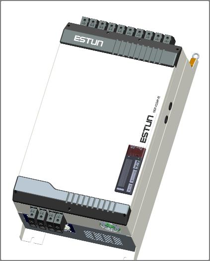


13 1.2 Part Names 1.2.1Servomotor Servomotor without gear and brake Servo drive
14 Chapter 2 Installation 2.1 Servomotor Servomotor can be installed either horizontally or vertically. However, if the servomotor is installed incorrectly, the service life of the servomotor will be shortened or unexpected problems may occur. Please observe the installation instructions described below to install the servomotor correctly. Before installation: Anticorrosive paint is coated on the edge of the servomotor shaft. Clean off the anticorrosive paint thoroughly using a cloth moistened with thinner. Avoid getting thinner on other parts of the servomotor when cleaning the shaft Storage When the servomotor is not being used, store it in an area with a temperature between -20 and 60 with thepower cable disconnected Installation Sites The servomotor is designed for indoor use.install the servomotor in an environment which meets the following conditions. Free from corrosive and explosive gases. Well-ventilated and free from dust and moisture. Ambient temperature from0 to 40. Relative humidity from 26% to 80%( non-condensing). Facilitates inspection and cleaning
15 2.1.3 Installation Alignment Align the shaft of the servomotor with that of the machinery shaft to be controlled. Then connect the two shafts with an elastic coupling.install the servomotor so that alignment accurancy falls within the range shown below. Measure this distance at four different positions in the circumference. The difference between the maximum and minimum measurements must be 0.03mm or less.(turn together with couplings.) Note: If the alignment accurancy is incorrect, vibration will occur, resulting in damage to the bearings. Mechanical shock to the shaft end is forbidden, otherwise it may result in damage to the encoder of the servomotor Installation Orientation Servomotor can be installed ethier horizontally or vertically Handling Oil and Water If the servomotor is used in a location that is subject to water or oil drops, make sure of the servomotor protective specification. If the servomotor is required to meet the protective specification to the through shaft section by default, use a servomotor with an oil seal. Through shaft section: It refers to the gap where the shaft protrudes from the end of the servomotor. Through Shaft Section
, handle it with adequate care. 2.1.")
16 2.1.6 Cable Tension When connecting the cables, the bending radius should not be too small, do not bend or apply tension to cables.since the conductor of a signal cable is very thin (0.2 mm or 0.3 mm), handle it with adequate care Install to the Client When the servo motor is mounted to the client, please firmly secure the servo motor by the screws with backing ringas shown in the figure. Installation orientation 2.2Servo Drive EHD series servo drive is a base-mounted type. Incorrect installation will cause problems. Always observe the installation instructions described below Storage When the servomotor is not being used, store it in an area with a temperature between -20 and 85 with the power cable disconnected Installation Sites Notes on installation are shown below. Situation When installed in a control panel When installed near aheating unit When installed near a source of vibration When installed in a location subject to Notes on installation Design the control panel size, unit layout, and cooling method so that the temperature around the periphery of the servo drive does not exceed 55. Suppress radiation heat from the heating unit and a temperature rise caused by convection so that the temperature around the periphery of the servo drive does not exceed 55. Install a vibration isolator underneath the servo drive to prevent it from receiving vibration. Take appropriate action to prevent corrosive gases. Corrosive gases do not immediately affect the servo drive, but will eventually cause contactor-related


17 corrosive gases Others devices to malfunction. Avoid installation in a hot and humid site or where excessive dust or iron powder is present in the air Installation Orientation Install the servo drive perpendicular to the wall as shown in the figure. The servo drive must be oriented this way because it is designed to be cooled by natural convection or a cooling fan if required Magnetism-circle twist Method Encoder wire magnetism-circle twist:put Encoder wire end twist magnetism-circle 将编码器线一端绕大磁环上 6 圈, 再将这段插头焊接上 磁环位置靠近电机侧 请见下图实例 : 2.3 Capacitancetrunk 2.3.1Capacitancetrunk spec Model capacity Rated Voltage CAP µF±20% 720VDC
18 Overvoltage Current Load Range temperature of 900VDC max 53Aeff.max -10 ~ Installation Dimension U nit : mm Installation Orientation Capacitancetrunkshould be installed to face to operator,and being vertical to installation base level MultipleCapacitancetrunk Installation When installing servo drives side by side, provide at least 50mm space above and below each one as well as shown in the ffollowing installation method,assure cooling effect by fan or natureconvection
19 EHDSeriesAC Servo User's Manual
20 Chapter 3 Wiring 3.1 Main Circuit Wiring Please observe the following instructions while wiring the main circuit. Do not bundle or run power and signal lines together in the same duct. Keep power andsignallines separated by at least 300 mm. Use twisted-pair shielded wires or multi-core twisted-pair shielded wires for signal and encoder feedback lines. The maximum length is 3 m for reference input lines and 20 m for encoder feedback lines. Do not touch the power terminals for 15 minutes after turning power OFF because high voltage may still remain in the servo drive Names and Functions of Main Circuit Terminals Terminal Symbol Name MainCircuit Voltage(V) Functions L1,L2,L3 U,V,W L1C,L2C Main circuitpower supplyinput terminal Servomotor connection terminals Control circuit power supply input terminal Ground terminals 400 Three-phase 380~440VAC +10% -15% (50Hz) - Connect to the servomotor. 400 Single-phase 380~440VAC +10% -15% (50Hz) - Connects to the power supply ground terminals and servomotor ground terminal. P,B External resistor terminal regenerative connection - Connect an external regenerative resistorbetween P and B N1,N2 DC reactor for harmonic uppression terminal - Normally short,if a countermeasure against power supply harmonic waves is needed, connect a DC reactor
21 3.1.2 Typical Main Circuit Wiring Examples Note The L1,L2,L3terminals wiring suggested brake type is:3ne A; Stand type suggest is:3nh C Connect an external regenerative resistor between Pand B,in series with brake,suggested brake type is:3ne A;Stand type suggest is:3nh3 120.Make sure that brake is connected between DCP terminal(p)an external regenerative resistor. Reactor or quickly melt is selected betweenn1 and N2 Capacitance trunk is selected between P andn1(n2)
22 3.2 I/O Signals Examples of I/O Signal Connections I/O Signal Names and Functions Input Signals Control Mode Speed Position Torque Signal Name Pin No. Function /S-ON 14 Servo ON:Turns the servomotoron. Function selected by parameter. /P-CON 15 Proportional Switches the speed control loop from PI to P control when control reference ON
23 Direction With the internally set speed selection:switch the rotation reference direction. Control switching mode Enables control mode switching. Zero-clamp Speed control with zero-clamp function:reference speed is reference zero when ON. Reference pulse Position control with reference pulse:stops reference pulse block input when ON. Forward run P-OT N-OT prohibited Reverse run Overtravelprohibited:Stops servomotor when OFF. prohibited Function selected by parameter. Forward external /PCL /NCL torque limit ON Reverse external torque limit ON Current limit function enabled when ON. Internal switching speed With the internally set speed selection: Switches the internal speed settings. /ALM-RST 39 Alarm reset: Releases the servo alarm state. DICOM 13 Control power supply input for I/O signals: Provide the +24V DC power supply Speed VREF+ 1 VREF- 2 Speed reference input: ±10V. PULS+ 30 Pulse reference input mode: Position PULS- 31 SIGN+ 32 SIGN- 33 PPI 34 /CLR 40 Sign + pulse train CCW + CW pulse Two-phase pulse (90º phase differential) Power supply input for open collector reference (2KΩ/0.5W resistor is built into the servo drive). Positional error pulse clear input: Clear the positional error pulse during position control. SHOM - Homing trigger signal(effective at the rising edge),allocated by Pn509 or Pn510 ORG - Zero Position(effective at high level), allocated by Pn509 or Pn510 Torque T-REF+ 26 T-REF- 27 Torque reference input: ±10V. Output signals Control Mode Signal Name Pin No. Function Speed /TGON+ 5 Detects when the servomotor is rotating at a speed higher than the motor
24 Position Torque Speed Position /TGON- 6 speed seeting. ALM+ 7 Servo alarm: ALM- 8 Turns off when an error is detected. /S-RDY+ /S-RDY Servo ready: ON if there is no servo alarm when the control/main circuit power supply is turned ON. PAO+ 20 Phase-A signal PAO- 21 Converted two-phase pulse(phases A and B) PBO+ 22 encoder output. Phase-B signal PBO- 23 PCO+ 24 PCO- 25 Phase-C signal Zero-point pulse(phase-c) signal FG Shell Connect frame to ground if the shield wire of the I/O signal cable is connected to the connector shell. /V-CMP+ 11 Speed coincidence: Detects whether the motor speed is within the setting range and if it /V-CMP- 12 matches the reference speed value. /COIN+ 11 Positioning completion: Turns ON when the number of positional error pulses reaches the value /COIN- 12 set. The setting is the number of positional error pulses set in the reference units. Reserved /CLT /BK 4,18,19,29,35 36,37,38,43 44,45,47,49 Reserved terminals: The functions allocated to /TGON, /S-RDY, and /V-CMP (/COIN) can be changed by using the parameters. /CLT:Torque limit output Turns on when it reaches the value set. /BK:Brake interlock output Releases the brake when ON, /PGC:C pulse output OT:Over travel signal output /RD:Servo enabled motor excitation output /HOME: Home completion output Not used I/O Signal Connector (CN1) Terminal Layout Terminal Terminal Name Function Name Function No. No. 1 VREF+ 26 T-REF+ Speed reference input:±10v Torque referenceinput:±10v 2 VREF- 27 T-REF- 3 DGND DGND 28 DGND DGND
25 4 Reserved 29 Reserved 5 /TGON+ 30 PULS+ Running signal output 6 /TGON- 31 PULS- Reference pulse input 7 ALM+ 32 SIGN+ Servo alarm 8 ALM- 33 SIGN- Reference sign input 9 /S-RDY+ Open collector reference 34 PPI Servo ready power supply 10 /S-RDY- 35 Reserved 11 /COIN+ 36 Reserved Positioning completion 12 /COIN- 37 Reserved 13 DICOM I/O signal power supply 24V DC 38 Reserved 14 /S-ON Servo ON 39 /ALM-RST Alarm reset 15 /P-CON P/PI control input 40 /CLR Position error pulseclear input 16 P-OT Forward run prohibited 41 /PCL Forward torque limitinput 17 N-OT Reverse run prohibited 42 /NCL Reverse torque limitinput 18 Reserved 43 Reserved 19 Reserved 44 Reserved 20 PAO+ PG dividing 45 Reserved 21 PAOpulse output PG phase A dividing 46 DGND DGND 22 PBO+ PG dividing pulse 47 Reserved 23 PBOpulse output output phase B 48 DGND DGND 24 PCO+ PG dividing 49 Reserved Zero-point pulse output 25 PCO- pulse 50 DGND DGND phase C Note:The functions allocated to the following input and output signals can be changed by using the parameters. Input signals:/s-on,/p-con,p-ot,n-ot,/alm-rst,/clr,/pcl,/ncl,shom,org Output signals:/tgon,/s-rdy,/coin,/home Please refer to A.3 Parameters in details for detailed information Interface Circuit This section shows examples of servo drive I/O signal connection to the host controller. Interface for Analog Reference Input Circuit Analog signals are either speed or torque reference signals at about 40kΩimpedance, and the maximum allowable voltages for input signals is ±10V. Reference speed input Reference torque input
26 Servodrive 470Ω(1/2W)min. 3 10V 2KΩ 2 T-REF 1 GND About 40KΩ 0V Interface for sequence input circuit The sequence input circuit interface connects through a relay or open-collector transistor circuit.select a low-current relay otherwise a faulty contact will result. Interface for line driver output circuit The amount of two-phase (phase A and phase B) pulse output signals (PAO,/PAO,PBO,/PBO) and zero-point pulse signals(pco,/pco) are output via line-driver output circuits.normally, the servo drive uses this output circuit in speed control to comprise the position control system at the host controller. Connect the line-driver output circuit through a line receiver circuit at the host controller. Interface for sequence output circuit Photocoupler output circuits are used for Servo Alarm (ALM), Servo Ready(S-RDY), and other sequence output signal circuits.connect a photocoupler output circuit through a relay circuit. 3.3 Wiring Encoders 3.3.1Connecting an Encoder(CN2) Resolver
27 3.3.2 Encoder Connector(CN2) Terminal Layout Resolver Terminal No. Name Function Terminal No. Name Function 7 SIN+ Differential Sine Signal 17 COS+ Differential Cosine Signal 8 SIN- Differential Sine Signal 18 COS- Differential Cosine Signal 9 R1 Excitation signal 19 R2 Excitation Signal 3.4 Communication Connection 3.4.1Communication Connector(CN3) Terminal Layout Terminal No. Name Function 1 Reserved RS-485 communication terminal 4 ISO_GND Isolated ground 5 ISO_GND RS-485 communication terminal 7 CANH CAN communication terminal 8 CANL CAN communication terminal
28 3.4.2 Communication Connector(CN4) Terminal Layout Terminal No. Name Function 1 Reserved RS-485 communication terminal 4 ISO_GND Isolated ground 5 ISO_GND RS-485 communication terminal 7 CANH CAN communication terminal 8 CANL CAN communication terminal 3.5 Motor Wiring Motor Plug Spec Signal U V W FG Colour Red Yellow Blue Green/Yellow Encoder Plug Spec Needle Number Signal Colour B Sensor1 Brown HMS3106A14S-2S (Including Cable nip) A Sensor2 Orange C FG shield HMS3108B20-29S (Including Cable nip) NeedleNumber Signal Colour K SIN+ Green L SIN- White T COS+ Blue S COS- Yellow H R1 Red G R2 Black N Sensor1 Brown R Sensor2 Orange J FG Shied
29 igns-op-cp-on-oalmclrp-cn-cferencev~v/raspeferenmo)magn1kticcontormbesuretoconectasurgesupresortotheexctioncoilofthemagneticontactorandrelayesolvehelshieldsbesuretogroundusespecialcommubesuretoprnioncableteparconecpc(personalcomputoretheenofthshieldedwireeqpropenryehdseriesac Servo User's Manual 3.6 Standard Wiring Examples L1 L2 L3 +10% Three Phase 380V -15%(50Hz) Surge Protector 1Ry 1PL (Servo Alarm Display) Noise Filter Power OFF Power ON 1KM 1KM 1Ry 1SUP el1 L2 L3 Breaker N1 N2 EHD Series Servodrive U V W Servomotor A(1) B(2) M C(3) D(4) L1C CN2 External Regeneration Resistor Breaker L2C B P r7 SIN+ 8 SIN- 17 COS+ 18 COS- 9 R1 19RR2 Shield SEncoder PG popen-collector Reference UseSeedReToPosition ReferenceSrqueRCN3 (±110ce(±1V~10V /Rated Torque) PULS / CW / A SIGN / CCW / B tededvref+ 1 VREF- 2 AGND 3 TREF+ 26 TREF- 27 AGND 28 CN1 PPI 34 PULS+ 30 PULS- 31 SIGN+ 32 SIGN K 40K ref + 40K - 10K + - 2KΩ 150Ω 2KΩ 150Ω ref A/D CN hel V +5V 485+ DGND DGND 485- CANH CANL N.C. N.C DGND DGND 485- CANH CANL Shell Shield calalocatonsndfin:servoonon:pcontrolt:forwardrunprohbitedt:reverserunprohbited-rst:alarmreset:cleareorpulsel:forwardtorquelimitl:reversetorquelimicabeconnect Shield to Connector Shell edt+24v :P P P PPatiotdeelDICOM 13 S-ON 14 P-CON 15 P-OT 16 N-OT 17 ALM-RST 39 CLR 40 P-CL 41 N-CL 42 Shield Shell 3.3KΩ PAO+ 21 PAO- 22 PBO+ 23 PBO- 24 PCO+ 25 PCO- 50 DGND 5 TGON+ 6 TGON- 9 S-RDY+ 10 S-RDY- 11 V-CMP+ 12 V-CMP- ALM+ ALM- )1Ry DvidedatioOutputAplicableLneReceiverAM26LS32ManufacturGp1D RiASignal allocatons can be modified: COIN: Positoning Completion TGON: Rotation Detection S-RDY: Servo Ready CLT: Torque Limit Detection BK: Brake Interlock PGC: Encoder C-Pulse Output OT:Over Travel RD:Servo Enabled Motor Excitation Output +24V edbytiortheuivaltp 0V ALM: Servo Alarm Output Represents Twisted-pair Wires Photocoupler Output: Maximum Operating Voltage:DC30V Maximum Output Current:DC50mA
30 SeriEHSesDervodriveeEuivenEHDSeriesAC Servo User's Manual Position Control Mode Position Reference ignals-on:p-cop-ot:n-ot:alm-clr:p-cl:n-cl:connect Shield to Connector ShellSalSN:FRRSClFRP P tp Shield Shell 7 8 l+24v oteo20 PAO+ 21 PAO- PGDvidedRatioOutput22 PBO+ AplicableLineReceive:AlarmResetN-OT 17 areorpulserwardtorquelimitalm-rst 39 eversetorquelimitclr 40 ocatonscanbemodfied:12 V-CMP- OT:Over Travel DICOM 13 RD:Servo Enabled Motor Excitation Output ervoon3.3kω PControlS-ON 14 rwardrunprohbitedp-con 15 everserunprohbitedopen-collector Reference Use r23 PBO- AM26LS32AManufacturqaPPI 34 2KΩ 24 PCO+ PULS / CW / A 150Ω PULS PCO- PULS DGND 2KΩ SIGN / CCW / B SIGN+ 32 SIGN Ω Signal allocatons can be modified: 5 TGON+ COIN: Positoning Completion 6 TGON- TGON: Rotation Detection 9 S-RDY+ S-RDY: Servo Ready CLT: Torque Limit Detection 10 S-RDY- BK: Brake Interlock 11 V-CMP+ PGC: Encoder C-Pulse Output P-OT 16 P-CL 41 N-CL 42 ALM+ ALM- 1Ry 1D +24V edbytiorthrepresents Twisted-pair Wires 0V ALM: Servo Alarm Output Photocoupler Output: Maximum Operating Voltage:DC30V Maximum Output Current:DC50mA
31 Speed Control Mode + A/D 3.3KΩ Connect Shield to Connector ShellSpeedReference(±1V~10V/RatedSpeed)Signalalocatonscanbemodified:S-ON:ServoONP-CON:PControlP-OT:ForwardRunProhibitedN-OT:ReverseRunProhibitedALM-RST:AlarmResetCLR:ClearErorPulseP-CL:ForwardTorqueLimitN-CL:ReverseTorqueLimit+24V PPGDividedRatioOutputApplicableLineReceiverAM26LS32AManufacturedbyTIortheEquivalentALM: Servo Alarm Output Photocoupler Output: Maximum Operating Voltage:DC30V Maximum Output Current:DC50mA - ref 40K 10K 40K 10K 1Ry 1D +24V 0V PAO+ 20 PAO- 21 PBO+ 22 PBO- 23 PCO+ 24 PCO- 25 DGND 50 TGON+ 5 TGON- 6 S-RDY+ 9 S-RDY- 10 V-CMP+ 11 V-CMP- 12 ALM+ 7 ALM- 8 VREF+ 1 VREF- 2 DICOM 13 S-ON 14 P-CON 15 P-OT 16 N-OT 17 ALM-RST 39 CLR 40 P-CL 41 N-CL 42 Shield Shell EHD Series Servodrive Signal allocatons can be modified: COIN: Positoning Completion TGON: Rotation Detection S-RDY: Servo Ready CLT: Torque Limit Detection BK: Brake Interlock PGC: Encoder C-Pulse Output OT:Over Travel RD:Servo Enabled Motor Excitation Output P Represents Twisted-pair Wires 3.6.3Torque Control Mode
32 ora/dtrfreigs-p-p-n-alclp-n-nocoomrccalocsern:pforrevrst:clearforwrevaln:ot:t:-:l:l:nbenservo Alarm Output talm: ncp EHDSeriesAC Servo User's Manual EHD Series Servodrive queconnect Shield to Connector ShellSedbycamoShield Shell 7 8 rreav+24v wee20 PAO+ 21 PAO- PGDvidedRatioOutput22 PBO+ AplicableLineReceiveAM26LS32AManufactuCLR 40 tonsedfied:12 V-CMPoONDICOM KΩ ControlS-ON 14 ardrunprohbited23 PBO- 24 PCO+ 25 PCO- (±1V~10V /Rated Torque) ref 50 DGND TREF TREF TGON+ 6 TGON- 9 S-RDY+ 10 S-RDY- 11 V-CMP+ P-CON 15 rserunprohbitedp-ot 16 AlarmResetN-OT 17 EorPulseardTorqueLimitALM-RST 39 rsetorquelimitp-cl 41 N-CL 42 ALM+ ALM- 1Ry 1D +24V TIortheEquivalSignal allocatons can be modified: COIN: Positoning Completion TGON: Rotation Detection S-RDY: Servo Ready CLT: Torque Limit Detection BK: Brake Interlock PGC: Encoder C-Pulse Output OT:Over Travel RD:Servo Enabled Motor Excitation Output 0V P Represents Twisted-pair Wires Photocoupler Output: Maximum Operating Voltage:DC30V Maximum Output Current:DC50mA 3.7 Wiring for Noise Control Noise Control The servodrive uses high-speed switching elements in the main circuit. It may receive "switching noise"from these high-speed switching elements. To prevent malfunction due to noise, take the following actions: Position the input reference device and noise filter as close to the servo drive as possible. Always install a surge absorber in the relay, solenoid and electromagnetic contactor coils. The distance between a power line (servomotor main circuit cable) and a signal line must be at least 30 cm.do not put the power and signal lines in the same duct or bundle them together. Do not share the power supply with an electric welder or electrical discharge machine. When the servo drive is placed near a high-frequency generator, install a noise filter on the input side of the power supplyline. As for the wiring of noise filter, refer to (1) Noise Filter shown below. For proper grounding technique, refer to (2) Correct Grounding. (1) Noise Filter Please install a noise filter in the appropriate place to protect the servo drive from external noise interference
33 Notice: AC 400V Noise filter * 3 Servo Drive L1 L2 L3 Servomotor M (FG) 3.5mm min. 2 * 1 L1C CN2 L2C CN1 PG 2 2mm min. Operation relay sequence Signal generation circuit * 3 * 2 Noise filter DC power 2 3.5mm min. (ground plate) (ground plate) Wires of 2 3.5mm min. * 1 (ground 2 3.5mm min. * 1 plate) (ground plate) (ground plate) Ground: Ground to an independent ground use ground resistor 100Ω max. For ground wires connected to the ground plate, use a thick wire with a thicknessof at least 3.5 mm 2 (preferably, plain stitch cooper wire) should be twisted-pair wires. When using a noise filter, follow the precautions in Precautions on Connecting Noise Filter. (2) Correct Grounding Take the following grounding measures to prevent the servo drive from malfunctioning due to noise. Grounding the Motor Frame If the servomotor is grounded via the machine, a switching noise current will flow from the servo drive main circuit through the servomotor stray capacitance. Always connect servomotor frame terminal FG to the servodrive ground terminal. Also be sure to ground the ground terminal. Noise on the I/O Signal Line If the I/O signal line receives noise, ground the 0 V line (SG) of the reference input line. If the main circuit wiring for the motor is accommodated in a metal conduit, ground the conduit and its junction box. For all grounding, ground at one point only. (3)Precautions on installing on the control panel When the servo driveis installed on the control panel, a piece of metal plate should be fixed. It is used for fixing the servo drive and other peripheral devices. The noise filter should be installed on the metal plate, and closed to the hole drill through power lines on control panel. Use screws to fix the noise filter to the metal plate. The grounding terminals of noise filter connects to the grounding terminals of control panel. Servo drive should be fixed on a piece of metal plate. Make sure the heat sink towards ground. The grounding terminals of servo drive connect to the grounding terminals of control panel
34 3.7.2 Precautions on Connecting Noise Filter (1) Noise Filter Brake Power Supply Use the noise filter Manufactured by SCHAFFNER at the brake power input for servomotors with holding brakes. Relationship between servo drive power and noise filter current: Servo Drive Power Noise Filter Current 35kW 200A 50kW 300A (2) Precautions on Using Noise Filters Do not put the input and output lines in the same duct or bundle them together. x Noise Filter Noise Filter Ground plate Ground plate Noise Filter Noise Filter Ground plate Ground plate Separate these circuits Separate the noise filter ground wire from the output lines. Do not accommodate the noise filter ground wire, output lines and other signal lines in the sameduct or bundle them together. X Noise Filter Noise Filter Ground plate Ground plate Connect the noise filter ground wire directly to the ground plate.do not connect the noise filter ground wire to other ground wires
35 x Noise Filter servodrive Noise Filter servodrive servodrive servodrive stub Shielded ground wire ground plate ground plate If a noise filter is located inside a control panel, connect the noise filter ground wire and the groundwires from other devices inside the control panel to the ground plate for the control panel first, thenground these wires. Control Panel Servodrive Noise Filter Servodrive Ground Ground plate 3.8 Installation Conditions of EMC Directives To adapt a combination of a servomotor and a servodrive to EMC Directives (EN :2006), the following conditions must be satisfied. (1) EMC Installation Conditions This section describes the installation conditions that satisfy EMC guidelines for each servo drive model. This section describes the EMC installation conditions satisfied in test conditions prepared by ESTUN. Theactual EMC level may differ depending on the actual system s configuration, wiring, and other conditions
36 Core Clamp Core Core Clamp Core Clamp Core EHDSeriesAC Servo User's Manual Ground/Shield Box Brake power supply Power Supply Three-phase 200VAC Three-phase 400VAC Servo Drive U,V,W Noise 4 filter 2 L1,L2,L3 L1C,L2C Brake Servomotor CN2 3 Encoder PE Aprox.2m CN1 Core 1 Aprox.5m PE Core Host controller Symbol Cable Name Specifications 1 I/O signal cable Shield cable 2 Servomotor cable Shield cable 3 Encoder cable Shield cable 4 AC line cable Shield cable.(2) Cable Core and Cable Clamp (a) Attaching the Ferrite Core The diagram shows two turns in the cable. The table shows the cable and the position where the ferrite core is attached. Cable Ferrite core Cable Name I/O signals cable Motor cable Encoder cable Mounting Position of the Core Near the host controller and servodrive. Near the servodrive and servomotor. Near the servodrive and servomotor. (b) Recommended Ferrite-core Cable Name Ferrite Core Model Manufacturer I/O signals cable Encoder cable ESD-SR-25 TOKIN Motor cable 400W or less 750W or less PC40T TDK (c) Fixing the Cable Fix and ground the cable shield using a piece of conductive metal. Example of Cable Clamp
37 Cable Shield(cable sheath stripped) Host controller side Ground plate Cable clamp Fix and ground the cable shield using a piece of conductive metal. Remove paint on mounting surface (d) Shield Box A shield box, which is a closed metallic enclosure, should be used for shielding magnetic interference. Thestructure of the box should allow the main body, door, and cooling unit to be attached to the ground. The boxopening should be as small as possible. 3.9 Using More than One Servo Drive The following diagram is an example of the wiring when more than one Servodrive is used. Connect the alarm output (ALM) terminals for the three Servodrives in series to enable alarm detection relay1ry to operate. When the alarm occurs, the ALM output signal transistor is turned OFF. Multiple servos can share a single molded-case circuit breaker (QF) or noise filter. Always select a QF or noisefilter that has enough capacity for the total power capacity (load conditions) of those servos
38 Power supply R S T QF Power OFF Power ON 1RY 1KM Noise filter 1KM SA 1KM +24 1RY L1 L2 L3 L1C L2C CN1 ALM+ ALM- Servo Drive Servo Motor M L1 Servo Drive L2 L3 L1C L2C CN1 ALM+ ALM- Servo Motor M 0V L1 L2 L3 L1C L2C CN1 ALM+ ALM- Servo Drive Servo Motor M Notes: 1.Power supply phase-s should connect to groundterminals
39 Chapter 4 Operation 4.1 Trial Operation Make sure that all wiring has been completed prior to trial operation. Perform the following three types of trial operation in order. Instructions are given for speed control mode (standard setting) and position control mode. Unless otherwise specified, the standard parameters for speed control mode (factory settings) are used. (1)Trial Operation for Servomotor Without Load (Refer to 4.1.1) Purpose The servomotor is operated without connecting the shaft to the machine in order to confirm the following wiring is correct. Power supply circuit wiring Servomotor wiring Encoder wiring Rotation direction and speed of servomotor. (Please refer to step 1-4) (2)Trial operation for servomotor with host reference (Refer to 4.1.2) Purpose The servomotor is operated without connecting the shaft to the machine in order to confirm the following wiring is correct. I/O signal wiring with host controller Rotation direction, speed and number of rotations of servomotor. Check the operation of the brake, overtravel and other protective functions. (Please refer to step 5-8) (3) Trial operation for servomotor and machine combined. (Refer to 4.1.3) Purpose Perform the trial operation with the servomotor connected to the machine. The servo drive is adjusted to match the machine characteristics. Servomotor speed and machine travel distance. Set the necessary parameters. (Please refer to step 9-11)
40 Step Item Description Reference 1 Installation Install the servomotor and servo drive according to the installation conditions. (Do not connect the servomotor to the machine because the servomotor will be operated first under the no-load condition for checking.) - 2 Wiring Connect the power supply circuit (L1, L2 and L3), servomotor wiring (U, V, W), I/O signal wiring (CN1), and encoder wiring (CN2). But during (1) Trial Operation for Servomotor Without Load, disconnect the CN1 connector. - Turn the power ON. Using the panel operator to make sure that the 3 Turn the power ON servo drive is running normally. If using a servomotor equipped with an absolute encoder, please perform the setup for the absolute - encoder. 4 Execute JOGoperatio n Execute JOG operation with the servomotor alone under the no-load condition. JOG Operation 5 Connect input signals Connect the input signals (CN1) necessary for trial operation to the servo drive. - 6 Check input signals Use the internal monitor function to check the input signals. Turn the power ON, and check the emergency stop, brake, overtravel, and other protective functions for the correct operation. - Input the 7 Servo-ON Input the Servo-ON signal, and turn ON the servomotor. Host Reference signal
41 8 Input Reference Input the reference necessary for control mode, and check the servomotor for correct operation. Host Reference 9 Protective operation Turn the power OFF, and connect the servomotor to the machine. If using a servomotor equipped with an absolute encoder, set up the absolute encoder and make the initial settings for the host controller - to match the machine s zero position. 10 Set necessary parameters. Using the same procedure as you did to input a reference in step 8,operate the servomotor via the host controller and set the parameter to make sure the machine s travel direction, travel distance, and travel speed allcorrespond to the reference. Host Reference 11 Operation The servomotor can now be operated. Adjust the servo gain if necessary. Host Reference Trial Operation for Servomotor Without Load Release the coupling between the servomotor and the machine, and secure only the servomotor without a load. To prevent accidents, initially perform the trial operation for servomotor under no-load conditions (with all couplings and belts disconnected). In this section, confirm the cable connections of the main circuit power supply, servomotor and encoder. Incorrect wiring is generally the reason why servomotors fail to operate properly during the trial operation. Confirm the wiring, and then conduct the trial operation for servomotor without load according to the following steps. Step Description Check Method and Remarks
42 1 Secure the servomotor. Secure the servomotor flange to the machine in order to prevent the servomotor frommoving during operation. Do not connect the servomotor shaft to the machine. The servomotor may tip over during rotation Check the power supply circuit, servomotor, and encoder With the I/O signal connector (CN1)disconnected, wiring. check the power supply circuit and servomotor wiring. Refer to 3.1 Main Circuit Wiring. Turn ON the control power supply and main circuit power If the power is correctly supplied, the panel operator supply. display on the front panel of the servo drive will appear Normal Display as shown on the left. The display on the left indicates that forward run prohibited (P-OT) and reverse run prohibited (N-OT). Alternate Display If an alarm display appears, the power supply circuit, Example of Alarm Display servomotor wiring, or encoder wiring is incorrect. If an alarm is displayed, turn OFF the power, find the problem, and correct it. When using a servomotor with a brake, release the brake Please refer to Setting for Holding Brakes first before driving the servomotor. Please refer to 4.5 Operating Using Speed Control When using a servomotor equipped with an absolute with Analog Reference encoder, the encoder setup is required before driving the servomotor. Use the panel operator to operate the servomotor with utility function Fn002 (JOG Mode Operation)Check that the servomotor rotates in the forwarddirection by pressing the INC key, and reverse direction bypressing the DEC key. The operation is completed when the operation is performed as described below and the alarm display does not appear. Complete the Fn002 (JOG Mode Operation) and turn OFF the power. For the operation method of the panel operator, refer to Chapter 5 Panel Operator The servomotor speed can be changed using the Pn305 (JOG Speed).The factory setting for JOG speed is 500rpm. JOG Mode Operation (Fn002) Step Display after operation Panel operator Description
43 1 MODE key 2 INC or DEC key 3 ENTER key 4 MODE key 5 INC or DEC key Press the MODE key to select the function mode. Press the INC key or DEC key to select Fn002. Press the ENTER key, and the servomotor will enter JOG operation mode. Press the MODE key. This will turn ON the power to the servomotor. The servomotor will run in forward direction when INC key is pressed or in reverse direction when DEC key is pressed. The servomotor will operate as long as the key is pressed. 6 MODE key 7 ENTER key Press the MODE key. This will turn OFF the power to the servomotor. Press the ENTER key to return to the Fn002 display of the utility function mode. Now, the servo driveisoff. Note: The servomotor s rotation direction depends on the setting of parameter Pn001.0(Direction Selection). The example above describes operation with Pn001.0 in the factory setting. JOG Speed S P To Pn305 Setting Range Setting Unit Factory Setting Setting Validation 0~6000 rpm 500 Immediately Set the utility function Fn002 (JOG Mode Operation) to the reference value of servomotor speed. The servomotor can be operated using only the panel operator without reference from the host controller. Please note that the Forward Run Prohibited (P-OT) and Reverse Run Prohibited (N-OT) signals are invalid during JOG mode operation Trial Operation for Servomotor without Load from Host Reference Check that the servomotor move reference or I/O signals are correctly set from the host controller to the servo drive. Also check the wiring and polarity between the host controller and servo drive, and the servo drive operation settings are correct. This is the final check before connecting the servomotor to the machine. (1)Servo ON Command from the Host The following circuits are required: External input signal circuit or equivalent
44 Speed Control (Standard Setting) [Pn005=H. 0 ] Position Control [Pn005=H. 1 ] +24V /S-ON P-OT N-OT V-REF CN V /S-ON P-OT N-OT PULS SIGN CN V 0V (2)Operating Procedure in Speed Control Mode (Pn005=H. 0 ) The following circuit is required: External input signal circuit or equivalent. Servodrive CN1 +24V 13 /S-ON 14 P-OT 16 N-OT 17 V-REF+ V-REF- V-REF+ V-REF- 0V 1 2 Max. Voltage (12V) GND 3 Step Description Check Method and Remarks Check the power and input signal circuits again, 1 and check that the speed reference input (voltage Refer to the above figure for the input signal circuit. between the V-REF+ and V-REF-) is 0V. 2 Turn ON the servo ON (/S-ON) input signal. If the servomotor rotates at an extremely slow speed, refer to Adjusting Reference Offset, and use thereference voltage offset to keep the servomotor from moving. 3 Generally increase the speed reference input voltage between V-REF+ and V-REF- from 0 V. The factory setting is 6V/rated rotation speed. 4 Check the speed reference input to the servo drive (Un001[rpm]) Refer to Operation in Monitor Mode. 5 Check the Un000 (motor speed [rpm]) Refer to Operation in Monitor Mode. 6 Check that the Un001 and Un000 values in steps 4 Change the speed reference input voltage and check that and 5 are equal. Un001 and Un000 are equal for multiple speed references
45 Check the speed reference input gain and 7 servomotor rotation direction. When the speed reference input is set to 0 V and 8 servo OFF status enters, trial operation for servomotor without load is completed. When Position Control is configured at the Host Refer to the following equation to change the speed reference input gain (Pn300). Un001=(V-REF Voltage)[V] Pn300 To change the servomotor rotation direction without changing polarity for speed reference input voltage, refer to Switching the Servomotor Rotation Direction. Perform the operation from step 2 again after the servomotor rotation direction is changed. Analog speed reference Host Controller Servodrive Position control Speed control Trial operation for servomotor without load When the servo drive conducts speed control and position control is conducted at the host controller, perform the operation below,following the operation in Operation Procedure in Speed Control Mode (Pn005=H. 0 ). Step Description Check Method and Remarks Check the input signal circuit again, and check that 9 the speed reference input (between the V-REF+ and V-REF-) is 0 V. 10 Turn the servo ON input signal (/S-ON) ON. Send the command for the number of servomotor rotations. Check the sent number of rotations, the 11 actual number of rotations by visual inspection, and the Un004 (rotation angle)[pulse] Refer to the above figure for input signal circuit. If the servomotor rotates at an extremely slow speed, refer to Adjusting Reference Offset, and use the reference voltage offset to keep theservomotor from moving. Refer to5.1.6 Operation in Monitor Mode for how it is displayed. Un004(rotation angle)[pulse]: The number of pulses from the zero point. 12 If the sent number of rotations and actual number of rotations in step 11 are not equal, correctly set the Pn200 (PG divided ratio) outputting the encoder pulse from the servo drive. Refer to Encoder Signal Output for how to set PG divided ratio (Pn200[P/Rev]):The number of encoder pulses per revolution. 13 When the speed reference input is set to 0 V and servo OFF status is entered, the trial operation for position control with the host controller is completed
46 (3)Operating Procedure in Position Control Mode (Pn005=H. 1 ) The following circuit is required: External input signal circuit or equivalent. Servodrive Reference pulse according to parameter Pn004.2 setting. Pulse reference +24V /S-ON P-OT N-OT CLR PULS /PULS SIGN /SIGN CN Step Description Check Method and Remarks 1 Match the reference pulse form with the pulse output form Set the reference pulse form with Pn from the host controller. 2 Set the reference unit and electronic gear ratio so that it Set the electronic gear ratio with Pn201(or coincides with the host controller setting. Pn203)/Pn Turn the power and the servo ON input signal ON. 4 Send the slow speed pulse reference for the number of servomotor rotation easy to check (for example, one Set the servomotor speed to100rpm for the reference pulse speedbecause such speed is safe. servomotor revolution) from the host controller in advance. 5 Check the number of reference pulses input to the servo drive by the changed amount before and after the Un013 and Un014(input reference pulsecounter)[pulse] were executed. Refer to5.1.6 Operation in Monitor Modefor how it is displayed. Check whether the actual number of servomotor Refer to5.1.6 Operation in Monitor Mode for how 6 rotationsun009 Un010 coincides with the number of input reference pulses. it is displayed. 7 Check that the servomotor rotation direction is the same as Check the input pulse polarity and input reference the reference. pulse form. 8 Input the pulse reference with the large number of servomotor rotation from the host controller to obtain the Set the servomotor speed to 100rpm for the reference pulse speed because such speed is safe. constant speed. 9 Check the reference pulse speed input to the servo drive using the Un008in Monitor Mode. (input reference pulse speed)[rpm]. Refer to5.1.6 Operation in Monitor Modefor how it is displayed. 10 Check the servomotor speed using the Un000 in Monitor Refer to5.1.6 Operation in Monitor Modefor how it Mode. (servomotor speed) [rpm]. is displayed. 11 Check the rotation of the servomotor shaft. To change the servomotor rotation direction without changing the input reference pulseform, refer to Switching theservomotor Rotation Direction. Perform the operation from step 8 again after the servomotor rotation direction is changed. 12 When the pulse reference input is stopped and servo OFF status is entered, the trial operation for servomotor without load in position control mode is complete


47 4.1.3Trial Operation with the Servomotor Connected to the Machine Follow the procedure below for trial operation precisely as given. Malfunctions that occur after the servomotor is connected to the machine not only damage the machine, but may also cause an accident resulting in death or injury. Follow the procedure below to perform the trial operation. Step Description Check Method and Remarks 1 Turn the power ON, and make the settings for the mechanical configuration related to protective functions such as overtravel and brake. Refer to 4.3 Setting Common Basic Functions. When a servomotor with brake is used, take advance measures to prevent vibration due to gravity acting on the machine or external forces before checking the brake operation. Check that both servomotor and brake operations are correct. For details, refer to Setting for Holding Brakes. 2 Set the necessary parameters for the control mode used. 3 Connect the servomotor to the machine with the coupling,etc.,while the power is OFF. Refer to 4.4 Operating Using Speed Control with Analog Reference,4.5 Operating Using Position Control, and 4.6 Operating Using Torque Controlfor control mode used
48 4 Check that the servo drive is servo OFF status and then turn ON the power to the machine (host controller). Check again that the protective function in step 1 operates normally. Refer to 4.3 Setting Common Basic Functions. For the following steps, take advanced measures for an emergency stop so that the servomotor can stop safely when an error occurs during operation. 5 Perform trial operation with the servomotor connected to the machine, following each section in Trial Operation for Servomotor without Load from Host Reference. 6 Check the parameter settings for control mode used in step 2. 7 Adjust the servo gain and improve the servomotor response characteristics, if necessary. 8 Thus, the trial operation with the servomotor connected to the machine is complete. Check that the trial operation is completedaccording to the trial operation for servomotor without load. Also, check the settings for machine such as reference unit. Check that the servomotor rotates matching the machine operating specifications. The servomotor will not be broken in completely during trial operation. Therefore, let the system run for a sufficient amount of time to ensure that it is properly broken in Trial Operation for Servomotor with Brakes Holding brake operation of the servomotor can be controlled with the brake interlock output (/BK) signal of the servo drive. When checking the brake operation,take advance measures to prevent vibration due to gravity acting on the machine or external forces. Check the servomotor operation and holding brake operation with the servomotor separated from the machine.if both operations are correct, connect the servomotor to the machine and perform trial operation. Refer to Setting for Holding Brakes for wiring on a servomotor with brakes and parameter settings Position Control by Host Controller As described above, be sure to separate the servomotor and machine before performing trial operation of the servomotor without a load. Refer to the following table, and check the servomotor operation and specifications in advance. Reference from the Host Controller JOG Operation(Constant speed reference input from host controller) Check Item Check Method Review Items Servomotor speed Check servomotor speed as Check the parameter setting at follows: Pn300 to see if reference Use the servomotor speed speed gain is correct
49 monitor(un000) on the panel operator. Run the servomotor at a low peed. For example, input a reference speed of 60rpm, and check to see if the servomotor makes one revolution per second. Simple positioning Number Input a reference equivalent to one Check the parameter setting at ofservomotor servomotor rotation, and visually Pn200 to see if the number of otation check to see if the shaft makes one PG dividing pulses is correct. revolution. Overtravel (P-OT and Whether the Check to see if the servomotor Review P-OT and N-OT wiring N-OT Used) servomotor stops stops when P-OT and N-OT signals if the servomotor does not rotating when are input during continuous stop. P-OT and servomotor operation. N-OT signals are input. 4.2Control Mode Selection The control modes supported by the EHD series servo drives are described below. Parameter Control Mode Reference Section Speed Control (Analog voltage reference) Controls servomotor speed using analog voltage speedreference. H. 0 Use in the following instances. To control speed 4.4 For position control using the encoder feedback divisionoutput from the servo drive to form a position loop inthe host controller. H. 1 Position Control(Pulse train reference) Controls the position of the servomotor using pulse train position reference. Controls the position with the number of input pulses, and controls the speed with the input pulse frequency. 4.5 Pn005 Use when positioning is required. H. 2 Torque Control (Analog voltage reference) Controls the servomotor s output torque with analog voltage torque reference. Use to output the required amount of torque for operations 4.6 such as pressing. H. 3 Speed Control(contact reference)speed Control (zero reference) Use the three input signals /P-CON,/P-CL and /N-CL to control the speed as set in advance in the servo drive. Three operating speeds can be set in the servo drive. (In this case, an analog reference is not necessary.)
50 H. 4 H. E These are swiching modes for using the four control methods described above in combination. Select the control method switching mode that best suits the application Setting Common Basic Functions 4.3.1Setting the Servo ON Signal This sets the servo ON signal (/S-ON) that determines whether the servomotor power is ON or OFF. (1)Servo ON signal(/s-on) Connector Pin Type Name Setting Meaning Number ON(low level) Servomotor power ON. Servomotor can beoperated. CN1-14 Input /S-ON Servomotor power OFF. Servomotor cannot be (Factory setting) OFF(high level) operated. Important Always input the servo ON signal before inputting the input reference to start or stop the servomotor. Do not input the input reference first and then use the /S-ON signal to start or stop. Doing so will degrade internal elements and may cause the servo drive to malfunction. A parameter can be used to re-allocate the input connector number for the /S-ON signal. Refer to I/O Signal Names and Functions. (2) Enabling/Disabling the Servo ON Signal A parameter can be always used to set the servo ON condition. This eliminates the need to wire /S-ON, but care must be taken because the servo drive can operate as soon as the power is turned ON. Parameter Meaning b. 0 External S-ON signal enabled (Factory setting) Pn000 External S-ON signal disabled, the servomotor excitation signal is b. 1 opened automatically after outputting the S-RDY signal. After changing these parameters, turn OFF the main circuit and control power supplies, and then turn them ON again to enable the new settings Switching the Servomotor Rotation Direction The rotation direction of the servomotor can be switched without changing the reference pulse to the servo drive or the reference voltage polarity. This causes the rotation the servo motor shaft is rotating to change. The output signal polarity, such as the encoder pulse output and the analog monitor signal from the servo drive do not change. The standard setting for forward rotation is counterclockwise as viewed from the servomotor load end. Reference Parameter Name Forward reference Reverse reference
51 b. 0 Standard setting (CCW=forward) CCW (factory setting) Encoder pulse division output CW Encoder pulse division output PAO PBO PAO PBO Pn001 b. 1 Reverse rotation mode (CW=forward) CW Encoder pulse division output PAO PBO CCW Encoder pulse division output PAO PBO The direction of P-OT and N-OT change. For Pn001=b. 0(standard setting), counterclockwise is P-OT. For Pn001=b. 1(reverse rotation mode), clockwise is P-OT Setting the Overtravel Limit Function The overtravel limit function forces movable machine parts to stop if they exceed the allowable range of motion and turn ON a limit switch. (1)Connecting the overtravel signal To use the overtravel function, connect the following overtravel limit switch to the corresponding pin number of servo drive CN1 connector correctly. Type Signal Name Pin No. Setting Meaning Input P-OT Forward rotation allowed. (Normal ON(low level) CN1-16 operation status.) (factory setting) Forward rotation prohibited. OFF(high level) (Forward overtravel) Input N-OT Reverse rotation (Normal operation ON(low level) CN1-17 status.) (factory setting) Reverse rotation prohibited. OFF(high level) (Reverse overtravel) Connect limit switches as shown below to prevent damage to the devices during linear motion. Rotation in the opposite direction is possible during overtravel. For example, reverse rotation is possible during forward overtravel. Important
52 When using overtravel to stop the servomotor during position control, the position error pulses are present. A clear signal(clr)input is required to clear the error pulses. When using the servomotor on a vertical axis, the workpiece may fall in the overtravel condition. To prevent this, always set the zero clamp after stopping with Pn004.0=5. (2)Enabling/Disabling the Overtravel Signal A parameter can be set to disable the overtravel signal. If the parameter is set, there is no need to wire the overtravel input signal. Parameter Meaning b. 0 Inputs the forward rotation prohibited(p-ot) signal from CN1-16(factory setting). b. 1 Disables the forward rotation prohibited (P-OT) signal. (Allows constant forward rotation.) Pn000 b. 0 Inputs the reverse rotation prohibited(n-ot) signal fromcn1-17.(factory setting) b. 1 Disables the reverse rotation prohibited(n-ot) signal. (Allows constant reverse rotation.) Applicable control modes: Speed control, position control, and torque control. After changing these parameters, turn OFF the main circuit and control power supplies, and then turn them ON again to enable the new settings. A parameter can be used to re-allocate input connector number for the P-OT and N-OT signals. Refer to I/O Signal Names and Functions. (3)Selecting the Servomotor Stop Method This is used to set the stop method when an overtravel(p-ot,n-ot)signal is input while theservomotor is operating. Mode After Parameter Stop Mode Meaning Stopping Stop by dynamic Rapidlly stops the servomotor by dynamic braking(db), H. 0 brake then places it into coast(power OFF) mode. Coast Stops the servomotor in the same way as when the H. 1 Coast to a stop servo is OFF(coast to a stop ), then places it into coast(power OFF) mode. Pn004 H. 2 Makes the servomotor coast to a stop state when servo H. 3 S-OFF OFF, stops the servomotor by plug braking when Coast /Overtravel overtravel, and then places it into coast (power OFF) mode
53 H. 4 H. 5 Zero Clamp Makes the servomotor coast to a stop state when servo OFF, stops the servomotor by plug braking when overtravel, then places it into zero clamp mode. After changing these parameters, turn OFF the main circuit and control power supplies, and then turn them ON again to enable the new settings. Stop by dynamic brake: Stops by using the dynamic brake (short circuiting its electrical circuit). Coast to a stop: Stops naturally, with no brake, by using the friction resistance of the servomotor in operation. Plug braking: Stops by using plug braking limit torque. Zero Clamp Mode: A mode forms a position loop by using theposition reference zero. Dynamic brake is an emergency stop function, and one of the general methods to cause a servomotor sudden stop. Dynamic brake suddenly stops a servomotor by shorting its electrical circuit. If the servomotor is frequently started and stopped by turning the power ON/OFF or using the servo ON signal(/s-on), the DB circuit will also be repeatedly operated, degrading the servo drive s internal elements. Use the speed input reference and position reference to control the starting and the stopping of the servomotor. (4)Setting the Stop Torque for Overtravel Plug braking torque limit` S P To Pn405 Setting Range Setting Unit Factory Setting Setting Validation 0~300 1% 300 Immediately This sets the stop torque for when the overtravel signal(p-ot,n-ot) is input. The setting unit is a percentage of the rated torque.(the rated torque is 100%) The value large enough to be the servomotor maximum torque, 300% is set as the factory setting for plug braking limit torque.however, the actual output plug braking limit torque is determined by servomotor ratings Setting for Holding Brakes The holding brake is used when the servo drive controls a vertical axis. A servomotor with the brake option helps prevent movable parts from shifting due to gravity when power is removed from the servo drive. (Refer to Trial Operation for Servomotor with Brakes.)
54 Vertical axis Servomotor Shaft with external force applied Holding brake External force Servomotor Prevents the servomotor from shifting due to gravity when the power is OFF. Prevents the servomotor from shifting due to external force. 1. The servomotor with the built in brake, is a de-energization brake. It is used to hold the servomotor and cannot be used as a braking purposes. Use the holding brake only to hold a stopped servomotor. 2. When operating using only a speed loop, turn OFF the servo and set the input reference to 0V when the brake is applied. 3. When forming a position loop, do not use a mechanical brake while the servomotor is stopped because the servomotor enters servolock status. (1)Wiring Example Use the servo drive sequence output signal /BK and the brake power supply to form a brake ON/OFF circuit. The following diagram shows a standard wiring example. Servodrive Servomotor with brake Power supply R L1 U S T L2 L3 V W M L1C BK-RY (/BK+) L2C CN1 *1 CN2 PG +24V (/BK-) *2 BK Brake power supply BK-RY Yellow or blue White AC DC Red Black BK-RY:Brake control relay 1* 2*:The output terminals allocated with Pn511. (2)Brake interlock output Type Signal Name Connector Pin Number Setting Meaning ON(Low level) Releases the brake. Output /BK Must be allocated OFF(High level) Applies the brake. This output signal controls the brake and is used only for a servomotor with a brake. This output signal is not used with the factory setting.the output signal must be allocated by Pn511. It does not need to be connected for servomotor without a brake. (3)Allocating Brake Interlock Output (/Bk)
55 Brake interlock output (/BK) is not used with the factory setting.the output signal must be allocated. Connector Pin Number Parameter + Terminal - Terminal Meaning Pn511 H. 4 CN1-11 CN1-12 The /BK signal is output from output terminal CN1-11,12. Pn511 H. 4 CN1-5 CN1-6 The /BK signal is output from output terminal CN1-5,6. Pn511 H. 4 CN1-9 CN1-10 The /BK signal is output from output terminal CN1-9,10. Important When set to the factory setting, the brake signal is invalid. For the allocation of servo drive output signals other than /BK signal, refer to I/O Signal Names and Functions. Parameter Pn511 description as following: 0 /COIN(/V-CMP)output 1 /TGON rotation detecting output 2 /S-RDY servo drive get ready output 3 /CLT torque limit output 4 /BKbrake interlock output 5 /PGC encoder C pulse output 6 OTovertravel signal output 7 /RD servo enabled motor excitation output 8 /HOME home completion output 9 /TCR Torque Detection Output Related parameter: Parameter Setting Name Unit No. Range Default Pn505 Servo ON waiting time ms -2000~ Pn506 Basic waiting flow 10ms 0~500 0 Pn507 Brake waiting speed rpm 10~ Pn508 Brake waiting time 10ms 10~ (4)Setting the Brake ON/OFF Timing after the Servomotor Stops With the factory setting, the /BK signal is output at the same time as the servo is turned OFF. The servo OFF timing can be changed with a parameter. Servo ON waiting time S Position To Pn505 Setting Range Setting Unit Factory Setting Setting Validation -2000~2000 ms 0 Immediately Instruction: Pn505 为正时, 当有伺服 ON 输入时首先输出 /BK 信号, 然后延时该参数设置的时间再给出电机励 磁信号 ; Pn505 为负时, 当有伺服 ON 输入时立即给出电机励磁信号, 然后延时该参数设置的时间再输出 /BK 信号 Position To
56 Basic waiting flow S Pn506 Setting Range Setting Unit Factory Setting Setting Validation 0~500 10ms 0 Immediately When using the servomotor to control a vertical axis, the machine movable parts may shift slightly depending on the brake ON/ OFF timing due to gravity or an external force. By using this parameter to delay turning the servo ON/ OFF, this slight shift can be eliminated. For details on brake operation while the servomotor is operating, refer to (5) Setting the Brake ON/ OFF Timing When Servomotor Running in this section. /CLT Torque limit output Pn511.0=3 CN1-11,CN1-12 Pn511.1=3 CN1-05,CN1-06 Pn511.2=3 CN1-09,CN1-10 Output terminal Important The servomotor will turn OFF immediately when an alarm occurs, regardless of the setting of this parameter. The machine movable part may shift due to gravity or external force during the time until the brake operates. (5)Setting the Brake ON/OFF Timing When Servomotor Running The following parameters can be used to change the /BK signal output conditions when a stop reference is output during servomotor operation due to the servo OFF or an alarm occuring. Brake Waiting Speed S P To Pn507 Setting Range Setting Unit Factory Setting Setting Validation 10~100 1rpm 100 Immediately Pn508 Brake Waiting Time S P To Setting Range Setting Unit Factory Setting Setting Validation 10~100 10ms 50 Immediately
57 /BK Signal Output Conditions When Servomotor Running The /BK signal goes to high level(brake ON) when either of the following conditions is satisfied: When the servomotor speed falls below the level set in Pn507 after servo OFF. When the time set in Pn508 is exceeded after servo OFF. /S-ON input or alarm or power OFF Servomotor Speed Servo ON Servo OFF Pn507 Servomotor stopped by applying DB or coasting. (Pn004.0) /BK Output Brake released Brake held Pn Instantaneous Power Loss Settings Determines whether to continue operation or turn the servo OFF when the power supply voltage to the servo drive main circuit is instantaneously interrupted. Parameter Signal Name and Meaning b.0 Continue operation when the power supply voltage to servo drive main circuit is Pn000 instantaneously interrupted. b.1 An alarm occurs when the power supply voltage to servo drive main circuit is instantaneously interrupted. 4.4 Operating Using Speed Control with Analog Reference Setting Parameters Parameter Meaning Pn005 H. 0 Control mode selection:speed control(analog reference)(factory setting) Speed Reference Input Gain S P To Pn300 Setting Range Setting Unit Factory Setting Setting Validation 0~3000 rpm/v 50 Immediately Sets the analog voltage level for the speed reference(v-ref) necessary to operate the servomotor at the rated speed. EXAMPLE Pn300=50:1V input is equivalent to the servomotor speed of 150rpm(factory setting)
58 4.4.2 Setting Input Signals (1)Speed Reference Input Input the speed reference to the servo drive using the analog voltage reference to control the servomotor speed in proportion to the input voltage. Type Signal Name Connector Pin Number Name V-Ref+ CN1-1 Speed Reference Input Input V-Ref- CN1-2 Speed Reference Input The above inputs are used for speed control(analog voltage reference).(pn005.1=0,4,7,9,a)pn300 is used to set the speed reference input gain.refer to Setting Parameters. (2)Proportional Control Reference (/P-CON) Connector Pin Tpye Signal Setting Meaning Number Operates the servo drive with proportional ON(low level) control Input /P-CON CN1-15 Operates the servo drive with proportional OFF(high level) integral control. /P-CON signal selects either the PI(proportional integral) or P(proportional) Speed Control Mode. Switching to P control reduces servomotor rotation and minute vibrations due to speed reference input drift. Input reference: At 0V, the servomotor rotation due to drift will be reduced, but servomotor rigidity (holding force) drops when the servomotor is stopped. Note: A parameter can be used to reallocate the input connector number for the /P-CON signal. Refer to I/O Signal Names and Functions Adjusting Reference Offset When using the speed control, the servomotor may rotate slowly even if 0V is specified as the analog voltage reference. This happens if the host controller or external circuit has a slight offset (in the unit of mv) in the reference voltage. Adjustments can be done manually or automatically by using the panel operator. Refer to 5.2 Operation in Utility Function Mode. The servo drive automatically adjusts the offset when the host controller or external circuit has the offset in the reference voltage
59 Reference Voltage Reference Voltage Offset Speed Reference Speed Reference Offset automatically adjusted in servodrive. Automatic offset adjustment After completion of the automatic adjustment, the amount of offset is stored in the servo drive. The amount of offset can be checked in the speed reference offset manual adjustment mode (Fn004). Refer to (2) Manual Adjustment of the Speed Reference Offset. (1) Automatic Adjustment of the Speed Reference Offset The automatic adjustment of reference offset (Fn003) cannot be used when a position loop has been formed with a host controller and the error pulse is changed to zero at the servomotor stop due to servolock. Use the speed reference offset manual adjustment (Fn004) described in the next section for a position loop. The zero-clamp speed control function can be used to force the servomotor to stop while the zero speed reference is given. Refer to4.4.7 Using the Zero Clamp Function. Note:The speed reference offset must be automatically adjusted with the servo OFF. Adjust the speed reference offset automatically in the following procedure. 1.Turn OFF the servo drive and input the 0V reference voltage from the host controller or external circuit. Servodrive Servomotor Host Controller 0V Speed Reference Servo OFF Slow rotation (Servo ON) 2.Press the MODE key to select the utility function mode. 3.Press the INC or DEC key to select parameter Fn Press the ENTER key to enter into the speed reference offset automatic adjustment mode. 5.Press the MODE key for more than one second, the reference offset will be automatically adjusted
60 6.Press ENTER key to return to the Fn003 display of the utility function mode. 7.Thus, the speed reference offset automatic adjustment is completed. (2)Manual Adjustment of the Speed Reference Offset Use the speed reference offset manual adjustment (Fn004) in the following situations: If a loop is formed with the host controller and the postion error pulse is set to be zero when servolock is stopped. To deliberately set the offset to some value To check the offset data set in the speed reference offset automatic adjustment mode. This function operates in the same way as the reference offset automatic adjustment mode (Fn003), except that the amount of offset is directly input during the adjustment. The offset setting range and setting unit are as follows: Adjust the speed reference offset manually in the following procedure. 1.Press the MODE key to select the utility function mode. 2. Press the INC or DEC key to select parameter Fn Press the ENTER key to enter into the speed reference offset manual adjustment mode. 4. Turn ON the servo ON (/S-ON) signal. The display will be shown as below. 5. Press the ENTER key for one second to display the speed reference offset amount. 6. Press the INC or DEC key to adjust the amount of offset. 7. Press the ENTER key for one second to return to the display in step Press the ENTER key to return to the Fn004 display of the utility function mode. Thus, the speed reference offset manual adjustment is completed
61 4.4.4 Soft Start The soft start function converts the stepwise speed reference inside the servo drive to a consistent rate of acceleration and deceleration. Pn310 can be used to select the soft start form: 0: Slope; 1: S curve; 2: 1 st -order filter; 3: 2 nd -order filter Soft Start Acceleration Time S Pn306 Setting Range Setting Unit Factory Setting Setting Validation 0~ ms 0 Immediately Soft Start Deceleration Time S Pn307 Setting Range Setting Unit Factory Setting Setting Validation 0~ ms 0 Immediately The soft start function enables smooth speed control when inputting a stepwise speed reference or when selecting internally set speeds. Set both Pn306 and Pn307 to 0 for normal speed control. Set these parameters as follows: Pn306:The time interval from the time the servomotor starts until the servomotor maximum speed is reached. Pn307:The time interval from the time the servomotor is operating at the servomotor maximum speed until it stops Speed Reference Filter Time Constant Speed Reference Filter Time Constant S Pn308 Setting Range Setting Unit Factory Setting Setting Validation 0~ ms 0 Immediately This smooths the speed reference by applying a 1 st order delay filter to the analog speed reference (V-REF) input. A value that is too large, however, will decrease response S-curve Risetime Pn309 S-curve Risetime S Setting Range Setting Unit Factory Setting Setting Validation 0~ ms 0 Immediately
62 4.4.7 Using the Zero Clamp Function (1)Zero Clamp Function The zero clamp function is used for systems where the host controller does not form a position loop for the speed reference input. When the zero clamp signal(/p-con)is ON, a position loop is formed inside the servo drive as soon as the input voltage of the speed reference (V-REF) drops below the servomotor zero clamp speed. The servomotor ignores the speed reference and quickly stops and locks the servomotor. The servomotor is clamped within ±1 pulse when the zero clamp function is turned ON, and will still return to the zero clamp position even if it is forcibly rotated by an external force. When the /P-CON signal is turned ON, a speed reference below the Pn502 setting is detected. Host Controller Speed Reference V-REF Zero Clamp /P-CON Stops precisely! (2)Parameter Setting Parameter Meaning Pn005 H. A Control mode: Speed control(analog voltage reference) Zero Clamp Zero Clamp Conditions: Zero clamp is performed with Pn005=H. A when the following two conditions are both satisfied: /P-CON is ON (low level) Speed reference (V-REF) drops below the setting in Pn502. Servodrive Speed V-REF speed reference Speed reference V-REF CN1 1 Preset value for zero clamping Pn502 Time Zero clamp /P-CON 15 /P-CON input Open(OFF) Closed(ON) Zero clamp is performed. ON OFF ON OFF ON
63 Pn502 Zero clamp speed Setting Range Setting Unit Factory Setting S Setting Validation 0~3000 rpm 10 Immediately Sets the servomotor speed at which the zero clamp is performed if zero clamp speed control(pn005=h. A ) is selected. Even if this value is set higher than the maximum speed of the servomotor, the maximum speed will be used. (3)Input Signal Setting Type Signal ame Connector Pin Number Setting Meaning Zero clamp function ON(low level) ON(enabled) Input /P-CON CN1-15 Zero clamp function OFF(high level) OFF(disabled) /P-CONis the input signals to switch to the zero clamp function Encoder Signal Output Encoder feedback pulses processed inside the servo drive can be output externally. Type Signal Name Connector Pin Number Name Output PAO CN1-20 Encoder output phase A /PAO CN1-21 Encoder output phase /A Output PBO CN1-22 Encoder output phase B /PBO CN1-23 Encoder output phase /B Output PCO CN1-24 Encoder output phase C(zero-point pulse) /PCO CN1-25 Encoder output phase /C(zero-point pulse) These outputs explained here. Servodrive Host Controller Encoder PG Serial Data CN2 * Frequency dividing circuit CN1 Phase A(PAO) Phase B(PBO) Phase C(PCO) *The dividing output phase form is the same as the standard setting(pn001.0=0) even if inreverse rotation mode(pn001.0=1). Output phase form
64 If the servomotor is not equipped with an absolute encoder, the servomotor needs two full rotations before using the servo drive's Phase-C pulse output as the zero point reference. Dividing:Dividing means that the divider converts data into the pulse density(pn200) based on the pulse data of the encoder installed on the servomotor, and outputs it. The setting unit isnumber of pulses/revolution
65 Pulse Dividing Ratio Setting PG Dividing Ratio S P T Pn200 Setting Range Setting Unit Factory Setting Setting Validation 16~ Puls After restart Set the number of pulses for PG output signals(pao,/pao,pbo,/pbo) externally from the servo drive. Feedback pulses from the encoder per revolution are divided inside the servo drive by the number set in Pn200 before being output. (Set according to the system specifications of the machine or host controller.) The setting range varies with the number of encoder pulses for the servomotor used. Output Example Pn200=16(when 16 pulses are output per revolution) Speed coincidence output The speed coincidence (/V-CMP) output signal is output when the actual servomotor speed during speed control is the same as the speed reference input. The host controller uses the signal as an interlock. Type Signal Name Connector Pin Number Setting Meaning CN1-11,12 ON(low level) Speed coincides. Output /V-CMP(/COIN) (factory setting) OFF(high level) Speed does not coincide. Pn501 Coincidence Difference Setting Range Setting Unit Factory Setting Setting Validation 0~100 rpm 10 Immediately The /V-CMP signal is output when the difference between the speed reference and actual servomotor speed is less than Pn501. Example The /V-CMP signal turns ON at 1900 to 2100rpm ifthe Pn501 parameter is set to 100 and the reference speed is 2000rpm. Note This pin outputs the /COIN signal in position control mode, and the /V-CMP signal in speed control mode. 4.5Operating Using Position Control Set the following parameters for position control using pulse trains
66 Parameter Meaning Pn005 H. 1 Control mode selection:position control(pulse train reference) A block diagram for position control is shown as below. Servodrive(in position control) Pn004.2 Pn112 Pn201 Differential Feed forward B A Pn202 Pn113 Feed forward filter time constant Pn111 Offset Pn500 Positioning complete Reference pulse Pn204 Smoothing Pn201 B A + Pn202 - Error counter Pn104 KP Speed loop Current loop Servomotor M PG signal output Pn200 dividing 4 PG Encoder Basic Setting in Position Control (1)Setting a reference pulse sign Type Signal Name Connector Pin Number Name PULS CN1-30 Reference pulse input Input /PULS CN1-31 Reference pulse input SIGN CN1-32 Reference sign input /SIGN CN1-33 Reference sign input (2)Settingreference input filter for open collector signal When Pn840.0=3/4/5 Pn006 0 when pulse is difference input, servo receiving pulse frequency 400K 1 when pulse is difference input, servo receiving pulse frequency 4M (3)Setting a Reference Pulse Form Set the input form for the servo drive using parameter Pn004.2 according to the host controllerspecifications. Parameter Pn004 H. 0 H. 1 Reference Pulse Form Sign+pulse train (positive logic) (factory setting) CW+CCW (positive logic) Input Pulse Multiplier H. 2 Two-phase pulse 1 H. 3 train with 90 2 H. 4 phase differential (positive logic) 4 Forward Rotation Reference PULS (CN1-30) SIGN (CN1-32) PULS (CN1-30) SIGN (CN1-32) H L Reverse Rotation Reverse PULS (CN1-30) SIGN (CN1-32) PULS (CN1-30) SIGN (CN1-32) L L
67 Note: The input pulse multiplier can be set for the two-phase pulse train with 90 phase differential reference pulse form. Forward Rotation Reverse Rotation PULS (CN1-30) SIGN (CN1-32) 1 倍 Internal processing 2 倍 Servomotor movement reference pulses. 4 倍 (4)Inverse PULS and SIGN reference Pn004 0 Do not inverse PULS reference and SIGN reference 1 Do not inverse PULS reference; Inverse SIGN reference 2 Inverse PULS reference; Do not inverse SIGN reference 3 Inverse PULS reference and SIGN reference (5)Reference Pulse Input Signal Timing Reference pulse signal form Electrical specifications Remarks Sign+pulse train input (SIGN+PULS signal) SIGN H=forward reference SIGN t1 t2 t7 t3 Maximum reference frequency : PULS t1,t2=0.1µs L=reverse reference t3,t7=0.1µs t4 t t5 t6 t4,t5,t6>3µs 500kpps(For open-collector output: T t=1.0µs (t /T) 100 = 50% Forward reference Reverse reference 200kpps) CW pulse+ccw pulse Maximum t1 reference frequency:500kpps (For open-collector output:200kpps) CCW CW t2 T t t3 t1,t2=0.1µs t3>3µs t=1.0µs (t /T) 100 = 50% Forward reference Reverse reference Two-phase pulse train with 90 phase A parameter differential(phase A +B) Maximum reference frequency: 1 input pulse multiplier:500kpps 2 input pulse multiplier:400kpps Phase A Phase B t1 t t2 T Forward reference Phase B leads A by 90º. Reverse reference Phase B lags B by 90º. t1,t2=0.1µs t=1.0µs (t /T) 100 = 50% Pn004.2 can be used to switch of the input pulse multiplier mode. 4 input pulse multiplier: 200kpps (6)Connection Example The pulse train output form from the host controller corresponds to the following: Line-driver Output +24V Open-collector output +12V/+5V Open-collector output
68 (a)connection Example for Line-driver Output Applicable line driver: SN75174 manufactured by TI or MC3487 or the equivalent. Host controller Servodrive Line-driver * PULS CN Ω Photocoupler /PULS 31 SIGN Ω /SIGN 33 * Represents twisted-pair wires (b)connection Example for Open-Collector Gate Output Hostcontroller Servodrive Tr1 * +24V PPI PULS /PULS +24V PPI CN1 34 2kΩ Ω 31 2kΩ 34 光电耦合器 电压为 +12V 时, 需分别在 PULS SIGN 外部串接一个电阻, 阻值为 1kΩ 电压为 +5V 时, 需分别在 PULS SIGN 外部串接一个电阻, 阻值为 180Ω ( 注 ) 光电耦合器输出时, 信号的逻辑如下所示 : SIGN /SIGN Ω Tr1 为 ON 时 Tr1 为 OFF 时 相当于 H 电平输入 相当于 L 电平输入 * 表示多股绞合线 Note : Whenthehostcontrolleris appliedbyopen-collectorsignaloutput,the inputsignalnoisemarginlowers.whenapositionerrorcausedbythenoiseoccurs,settheparameterpn
69 4.5.2Setting the Clear Signal (1)Setting the Clear Signal Type Sign Name Connector Pin Numbe Function Input /CLR 1CN-40 error counter clear When the /CLR signal is set to low level, clear error counter: The error counter inside the servo drive is set to 0 Position loop operation is disabled. (2)Setting the Clear SignalMode In positioncontrol mode, pulses will be still presented in the servo drive when servo OFF, thus it should be cleared when servo drive is turned ON. Setting Pn004 to choose whether clearing the pulses automatically when servo OFF. Pn Clearthe error pulse when S-OFF, donot whenovertravel. Do not clear the error pulse. Clearthe error pulse when S-OFF orovertravel (excep for zero clamp) 4.5.3Setting the Electronic Gear (1)Electronic Gear The electronic gear enables the workpiece travel distance per input reference pulse from the host controller to be set to any value. One reference pulse from the host controller, i.e., the minimum position data unit, is called a reference unit. No. of encoder pulses:32768 When the Electronic Gear is Not Used workpiece Ball screw pitch:6mm To move a workpiece 10mm : One revolution is 6mm. Therefore 10 6= revolutions pulses is one revolution. Therefore, = pulses pulses are input as reference pulses. The equation must be calculated at the host controller. No. of encoder pulses:32768 When the Electronic Gear is Used workpiece Reference unit:1µm Ball screw pitch:6mm To move a workpiece 10mm using reference units: The reference unit is 1µm. Therefore, to move the workpiece 10mm (10000µm), 1pulse=1µm, so 10000/1=10000 pulses. Input pulses per 10mm of workpiece movement. (2)Related Parameters Pn201 Electronic Gear Ratio(Numerator) Position Setting Range Setting Unit Factory Setting Setting Validation 1~ After restart Electronic Gear Ratio(Denominator) Position Pn202 Setting Range Setting Unit Factory Setting Setting Validation 1~ After restart The deceleration ratio of the servomotor and the load shaft is given as n/m where m is the rotation of the servomotor and n is the rotation of the load shaft. Electronic gear ratio: B Pn201 A Pn
. Important Electronic gear ratio setting range: 0.")
Procedure for Setting the Electronic Gear Ratio Use the following procedure to set the electronic gear ratio. Step Operation Description 1 Check machine specifications.")

70 No. of encoder pulses 4 m Travel dis tan ce per load n shaft revolution( reference units) If the ratio is outside the setting range, reduce the fraction (both numerator and denominator) until you obtain integers within the range. Be careful not to change the electronic gear ratio (B/A). Important Electronic gear ratio setting range: 0.01 electronic gear ratio(b/a) 100 If the electronic gear ratio is outside this range, the servo drive will not operate properly. In this case, modify the load configuration or reference unit. (3)Procedure for Setting the Electronic Gear Ratio Use the following procedure to set the electronic gear ratio. Step Operation Description 1 Check machine specifications. Check the deceleration ratio, ball screw pitch and pulley diameter. 2 Check the number of encoder pulses. Check the number of encoder pulses for the servomotor used. Determine the reference unit from the host controller, 3 Determine the reference unit used. considering the machine specifications and positioning 4 Calculate the travel distance per load shaft revolution. accuracy. Calculate the number of reference units necessary to turn the load shaft one revolution based on the previously determined reference units.s 5 Calculate the electronic gear ratio. Use the electronic gear ratio equation to calculate the ratio (B/A). 6 Set parameters. Set parameters using the calculated values. (4)Electronic Gear Ratio Setting Examples The following examples show electronic gear ratio settings for different load configurations. Load Configuration Ball Screw Disc Table Belt and Pulley Reference unit:0.01mm Step Operation Reference unit:0.001mm Load shaft Load shaft 17-bit encoder Ball screw pitch:6mm Deceleration ratio: 2:1 Pulley diameter: F 100mm 17-bit encoder 1 Check machine specifications. Ball screw pitch:mm Deceleration ratio:1/1 Rotation angle per revolution :360 Deceleration ratio:3/1 Pulley diameter:100 mm (pulley circumference:314 mm) Deceleration ratio:2/1 2 Encoder Revolve:16384P/R Revolve:16384P/R Revolve:16384P/R 3 Determine the reference unit used 1 reference unit: 0.001mm(1μm) 1 reference unit:0.1 1 reference unit:0.01mm Calculate the 4 travel distance per load shaft 6mm/0.001mm= /0.1 = mm/0.01mm=
71 5 revolution Calculate the electronic gear ratio 6 Set parameters 7 Final Result B A B A B A Pn Pn Pn Pn Pn Pn Pn Pn Pn Pn Pn Pn Reduce the fraction (both numerator and denominator) if the calculated result will not be within the setting range. For example, reduce the above numerators and denominators by four or other numbers to obtain the final results in step 7 and complete the settings. (5)Electronic Gear Ratio Equation 2 1 Servomotor n Reference pulse ( mm / P) B A + Position loop Speed loop m Pitch=P(mm/rev) ( mm / P) : Reference unit PG(P/rev)): Encoder pulses P(mm/rev):Ball screw pitch m n :Deceleration ratio n p B ( ) 4 PG m A B 4 PG m 4 P ) A n p P m n 4 PG(P/rev)) G ( Set A and B with the following parameters: A :Pn202 B :Pn Smoothing A filter can be applied in the servo drive to a constant-frequency reference pulse. (1)Selecting a Position Reference Filter Parameter Pn205 Description 0:1 st -order filter 1:2 nd -order filter * After changing the parameter, turn OFF the power once and turn it ON again to enable the new setting. (2)Filter-related Parameters Position Reference Acceleration/Deceleration Time Constant Pn204 Setting Range Setting Unit Factory Setting Setting Validation 0~ ms 0 Immediately Important P
72 When the position reference acceleration/deceleration time constant (Pn204) is changed, a value with no reference pulse input and a position error of 0 will be enabled. To ensure that the setting value is correctly reflected, stop the reference pulse from the host controller and input the clear signal (CLR), or turn OFF to clear the error. This function provides smooth servomotor operation in the following cases. When the host controller that outputs a reference that cannot perform acceleration/deceleration processing. When the reference pulse frequency is too low. When the reference electronic gear ratio is too high (i.e., 10 or more) 4.5.5Positioning Completion Output Signal This signal indicates that servomotor movement has been completed during position control. Use the signal as an interlock to confirm that positioning has been completedat the host controller. Type Signal Name Connector Pin Number Setting Meaning CN1-11,CN1-12 ON(low level) Positioning has been Output /COIN (Factory setting) completed. OFF(high level) Positioning is not completed. This output signal can be allocated to an output terminal with parameter Pn511. Refer to I/O Signal Names and Functions. The factory setting is allocated to CN1-11,12. Positioning Error P Pn500 Setting Range Setting Unit Factory Setting Setting Validation 0~5000 1Puls 10 Immediately The positioning completion (/COIN) signal is output when the difference (position error pulse) between the number of reference pulses output by the host controller and the travel distance of the servomotor is less than the value set in this parameter and the stabilization time is more than the value of Pn520. Set the number of error pulses in reference unit (the number of input pulses defined using the electronic gear). Too large a value at this parameter may output only a small error during low-speed operation that will cause the /COIN signal to be output continuously. The positioning error setting has no effect on final positioning accuracy. Note /COIN is a position control signal. This signal is used for the speed coincidence output /V-CMP for speed control, and it always OFF(high level) for torque control
73 4.5.6Reference Pulse Inhibit Function(INHIBIT) (1)Description This function inhibits the servo drive from counting input pulses during position control. The servomotor remains locked (clamped) while pulses are inhibited. Servodrive Pn005.1 Pn005=H. 1 Reference pulse Pn005=H. B ON OFF + - Error Counter /P-CON /P-CON Feedback pulse (2)Setting Parameters Parameter Meaning Pn005 H. B Control mode selection:position control(pulse train reference) INHIBIT Inhibit(INHIBIT) switching condition /P-CON signal ON (low level) (3)Setting Input Signals Type Signal Name Connector Number Pin Setting Meaning Turns the INHIBIT function ON. ON(low level) (Inhibit the servo drive from countingreference Input /P-CON CN1-15 pulses) OFF(high level) Turns the INHIBIT function OFF. (Counters reference pulses.)
74 4.5.7Position Control (contact reference) Position control under contact reference (parameter Pn005.1=C). In this mode, servo drive can position with a single axes without a host controller. There are 16 position control points with each being able to set move distance, running speed, constants for position reference filter time, and the stop time when positioning completed. Two speeds (1. speed moving toward distance switch speed of looking for reference point. 2. Speed moving away from distance switch moving speed. ) of reference points could be set as: Two position modes: 1. Absolute position mode 2. Relative position mode Two running modes: 1. Circling mode 2. Non-circling mode Two step switching method: 1. Delay step switching 2. /P-CON signal switching Method of looking for reference points: 1. Forward direction 2. Reverse direction Adjusting offset Offset of each points has two correspondent parameters: one unit of the parameter is x reference pulse and the other is x 1 reference pulse. Setting range of both parameters is: ( ), while offset value equals sum of those two values. For example: No.0 offset correspond to parameter Pn600 x reference pulse and Pn601 x 1 reference pulse. Set Pn600 = 100, Pn601=-100. No.0 offset value = Pn600x10000 reference pulse + Pn601x1 reference pulse = 100x10000 reference pulse + (-100)x1 reference pulse = reference pulse With the same principle, we can conclude: in order to get the same results, we also can set Pn600 = 99 and Pn601 = Thus, we can see when the two parameters are not zero; we can get same result by two ways: one is to set the two parameters both negative or both positive, or one negative the other positive. Speed Speed mentioned here refers to the steady speed during which the motor is running, which is similar to the pulse frequency given from the external pulse reference in position control.however, this speed has nothing to do with the electronic gear; it is the actual speed of the motor. Position reference filter time constant Same as position reference filter time constant Pn204 in common position control. Time for change steps after desired position reached Apply internal delay to change steps to a valid value in parameter Pn Time for change steps outputs from positioning completed signal CON/, from Servo ON, or from the time when reference point is found till the Servo performs the program to control position of the point. Such period of time depends on step changing time required by a point number among start point in program. When running point control program, if error counter is set as not clear error counter when Servo OFF, then the error counter might flood. If it does not flood, then the servo drive will probably run at the max. running speed when Servo ON again. PLEASE PAY ATTENTION TO THE SAFETY OF INSTRUMENT
75 Para. No. Pn004.1 Name and description [0] Clear error pulse when S-0FF, not clear error pulse when overtravel. [1] Not clear error pulse [2] Clear error pulse When S-OFF or over travel Setting range Default 0~2 0 Looking for the reference point Looking for the reference point is for establishing a zero physical point of the operating platform, which is used as zero point in the coordinates during point position control. And users may choose to find a reference point either in forward or reverse side. How to find a reference point Mount a limit switch in the forward or reverse side.find a reference point in the forward direction after connecting to /PCL and in the reverse direction after connecting to /NCL. When the operating platform bumps into the limit the switch, the motor will first stop according to the way set by Pn004.0, and then rotate again against limit the switch. When the operating platform leaves the limit switch and the motor reaches the position of first photo encoder Phase C pulse,then position of operating platform is set to be the zero point of the coordinates. How to find related parameters of reference point Speed towards limit switch is called speed of looking for reference point, and the moving speed away from limit switch is called moving speed. These two speeds could be set by the following parameters: Para. No. Description Unit Setting range Default Speed of looking for reference point (hits Pn685 rpm 0~ the limit switch) Moving speed (move away from limit Pn686 rpm 0~ switch) Usually, the set speed of the reference point (Pn685) is high, and the moving speed (Pn686) is low. Note: if moving speed is too high, precision of finding a reference point would be affected. When looking for a reference point, /PCL and /NCL are no longer programmed to limit external current. Related parameter Para. No. Description Observation Pn681.0 Choose between cycle run and single run. 0: Cycle run, /PCL as start signal, /NCL reverse to look for reference point. 1: Single run, /PCL as start signal, /NCL reverse to look for reference point. 2. Cycle run, /NCL as start signal, /PCL reverse to look for reference point. 3. Single run, /NCL as start signal, /PCL reverse to look for reference point. Changing steps will be performed till the end point is completed comma and the next change will start from the start point during multi-points cycle run. Point control program will not change steps after the end point is completed during multi- points single run
76 Pn681.1 Pn681.2 Pn682 Change step and start mode 0: Delay changing steps, the start signal is not needed. 1: Change steps by /P-CON, start signal not needed. 2. Delay changing steps, need start signal. 3. Change steps by /P-CON, need start signal. Change step input signal mode [0] High or low level [1] sign pulse 0: Incremental 1: Absolute Change steps by external /P-CON signals. The signal will be valid when drive output reaches the desired position. When input signal changes, the signal is valid, then steps will be changed by consequence from start point to end point. Incremental: relative moving distance (distance from current point to next point) programming. Absolute: absolute moving distance (distance between operating platform and the reference point) programming. 4.6Operating Using Torque Control Setting Parameters The following parameters must be set for torque control operation with analog voltage reference. Parameter Meaning Pn005 H. 2 Control mode selection:torque control(analog voltage reference) Torque Reference Input Gain S P T Pn400 Setting Range Setting Unit Factory Setting Setting Validation 10~ V/100% 33 Immediately This sets the analog voltage level for the torque reference(t-ref) that is necessary to operate the servomotor at the rated torque. Example Pn400=30:The servomotor operates at the rated torque with 3V input (factory setting). Pn400=100:The servomotor operates at the rated torque with 10V input. Pn400=20:The servomotor operates at the rated torque with 2V input
77 4.6.2 Torque Reference Input By applying a torque reference determined by the analog voltage reference to the servo drive, the servomotor torque can be controlled in proportion with the input voltage. Type Signal Name Connector Pin Number Meaning T-REF+ CN1-26 Input Torque Reference Input T-REF- CN1-27 Used during torque control (analog voltage reference) (Pn005.1=2,6,8,9) The torque reference input gain is set in Pn400. For setting details, refer to Setting Parameters. Input specifications Input range:dc±0~±10v/rated torque Factory setting Pn400=30:Rated torque at 3V +3V input:rated torque in forward direction +9V input:300% rated torque in forward direction -0.3V input:10% rated torque in reverse direction The voltage input range can be changed with parameter Pn400. Factory setting 300 Reference torque(%) Input voltage(v) Set the slope with Pn Input circuit example Use twisted-pair wires as a countermeasure against noise. +12V 470O 1/2W min. 2KO Servodrive CN1 T-REF+ 26 T-REF- 27 GND Checking the internal torque reference 1.Checking the internal torque reference with the panel operator. Use the Monitor Mode(Un003). Refer to Operation in Monitor Mode. 2.Checking the internal torque reference with an analog monitor. The internal torque reference can also be checked with an analog monitor Adjusting the Reference Offset (1)Automatic Adjustment of the Torque Reference Offset When using torque control, the servomotor may rotate slowly even when 0V is specified as the analog reference voltage. This occurs when the host controller or external circuit has a slight offset (measured in mv) in the reference voltage. In this case, the reference offset can be adjusted automatically and manually using the panel operator. The automatic adjustment of analog(speed,torque) reference offset(fn003) automatically measures the offset and adjusts the reference voltage. The servo drive performs the following automatic adjustment when the host controller or external circuit has an offset in the reference voltage
78 Reference voltage Reference voltage Offset Torque reference Torque reference Offset automatically adjusted in the servodrive. Automatic offset adjustment After completion of the automatic adjustment, the amount of offset is stored in the servo drive. The amount of offset can be checked in the manual adjustment of torque reference offset(fn004). The automatic adjustment of analog reference offset(fn003) cannot be used when a position loop has been formed with the host controller and the error pulse is changed to zero at the servomotor stop due to servolock. Use the torque reference offset manual adjustment(fn004). Note: The analog reference offset must be automatically adjusted with the servo OFF. (2)Manual Adjustment of the Torque Reference Offset Manual adjustment of the torque reference offset(fn004) is used in the following cases. If a position loop is formed with the host controller and the error is zeroed when servolock is stopped. To deliberately set the offset to some value. Use this mode to check the offset data that was set in the automatic adjustment mode of the torque reference offset. This mode operates in the same way as the automatic adjustment mode(fn003), except that the amount of offset is directly input during the adjustment. The offset adjustment range and setting unit are as follows. Torque reference Offset adjustment range Offset setting unit Offset adjustment range: -1024~+1024 Analog voltage input Limiting Servomotor Speed During Torque Control During torque control, the servomotor is controlled to output the specified torque, which means that the servomotor speed is not controlled. Accordingly, when an excessive reference torque is set for the mechanical load torque, it will prevail over the mechanical load torque and the servomotor speed will greatly increase. This function serves to limit the servomotor speed during torque control to protect the machine. Without Speed Limit With Speed Limit
79 (1)Speed Limit Enable Parameter Description b. 0 Use the value set in Pn406 as the speed limit (Internal speed limit ) Pn001 Usethe lower speed between V-REF and Pn406 as an external speed limit b. 1 input.(external speed limit) (2)Speed Limit During Torque Control Speed Limit During Torque Control Torque Pn406 Setting Range Setting Unit Factory Setting Setting Validation 0~6000 rpm 200 Immediately Set the servomotor speed limit value during torque control. Pn005=H. 1,Pn406 is motor speed limit value. The servomotor s maximum speed will be used when the setting in this parameter exceeds the maximum speed of the servomotor used. (3)External Speed Limit Function Type Signal Name Connector Pin Number Name Input V-REF+ CN1-1 V-REF- CN1-2 External Speed Limit Input Inputs an analog voltage reference as the servomotor speed limit value during torque control. The smaller value is enabled, the speed limit input from V-REF or the Pn406 (speed limit during torque control) when Pn005=H. 1. The setting in Pn300 determines the voltage level to be input as the limit value. Polarity has no effect. Speed Reference Input Gain S P To Pn300 Setting Range Setting Unit Factory Setting Setting Validation 0~3000 rpm/v 50 Immediately Set the voltage level for the speed that is to be externally limited during torque control. Pn300=150( 出厂时的设定 ) 时, 如果输入 V-REF(CN1-1,2) 的 6V 电压, 则将实际转速限制为所用伺服电机的额定转速 4.7Operating Using Speed Control with an Internally Set Speed The function of internally set speed selection allows speed control operation by externally selecting an input signal from among seven servomotor speed setting made in advance with parameters in the servo drive. The speed control operations within the three settings are valid. There is no need for an external speed or pulse generator
80 Servodrive CN1 Internally set speed parameters Contact inputs /P-CON /P-CL SPEED1 Pn316 SPEED2 Pn317 SPEED3 Pn318 SPEED4 Pn319 Speed reference Servomotor M SPEED5 Pn320 /N-CL 42 SPEED6 Pn321 SPEED7 Pn Setting Parameters Parameter Meaning Pn005 H. 3 Control mode selection: Speed control(contact reference) Speed control(zero reference) Internal set speed 1 sp Pn316 Setting Range Setting Unit Factory Setting Setting Validation -6000~6000 rpm 30 Immediately Internal set speed 2 sp Pn317 Setting Range Setting Unit Factory Setting Setting Validation -6000~6000 rpm 50 Immediately Internal set speed 3 sp Pn318 Setting Range Setting Unit Factory Setting Setting Validation -6000~6000 rpm 100 Immediately Internal set speed 4 sp Pn319 Setting Range Setting Unit Factory Setting Setting Validation -6000~6000 rpm -30 Immediately Internal set speed 5 sp Pn320 Setting Range Setting Unit Factory Setting Setting Validation -6000~6000 rpm -50 Immediately Internal set speed 6 sp Pn321 Setting Range Setting Unit Factory Setting Setting Validation -6000~6000 rpm -100 Immediately Internal set speed 7 sp Pn322 Setting Range Setting Unit Factory Setting Setting Validation -6000~6000 rpm 200 Immediately (Note):The servomotor s maximum speed will be used whenever a speed setting for the Pn316~Pn322 exceeds the maximum speed
81 4.7.2 Input Signal Settings The following input signals are used to switch the operating speed. Type Signal Name Connector Pin Number Meaning Input /P-CON CN1-15 Selects the internally set speed. Input /P-CL CN1-41 Selects the internally set speed. Input /N-CL CN1-42 Selects the internally set speed Operating Using an Internally Set Speed Use ON/OFF combinations of the following input signals to operate with the internally set speeds. When Pn005.1=3: Selects the internally set speed (contact reference) Speed control (zero reference) Input Signal Speed /P-CON /P-CL /N-CL OFF(H) OFF(H) Speed control (zero reference) OFF(H) OFF(H) ON(L) SPEED1 ON(L) OFF(H) SPEED2 ON(L) ON(L) SPEED3 OFF(H) OFF(H) SPEED4 ON(L) OFF(H) ON(L) SPEED5 ON(L) OFF(H) SPEED6 ON(L) ON(L) SPEED7 Note: OFF= High level; ON= Low level Control Mode Switching When Pn005.1 = 4,5,6, and either /P-CL or /N-CL is OFF (high level), the control mode will switch. Example: When Pn005.1=5: Speed control(contact reference)position control (pulse train) Input Signal Speed /P-CON /P-CL /N-CL OFF(H) OFF(H) Pulse train reference input (position control) OFF(H) OFF(H) ON(L) SPEED1 ON(L) OFF(H) SPEED2 ON(L) ON(L) SPEED3 OFF(H) OFF(H) SPEED4 ON(L) OFF(H) ON(L) SPEED5 ON(L) OFF(H) SPEED6 ON(L) ON(L) SPEED7 4.8 Limiting Torque The servo drive provides the following three methods for limiting output torque to protect the machine. NO. Limiting Method Reference Section
82 1 Internal torque limit External torque limit Torque limiting by analog voltage reference Internal Torque Limit Maximum torque is always limited to the values set in the following parameters. Forward Torque Limit S P To Pn401 Setting Range Setting Unit Factory Seeting Setting Validation 0~300 1% 300 Immediately Reverse Torque Limit S P To Pn402 Setting Range Setting Unit Factory Seeting Setting Validation 0~300 1% 300 Immediately The setting unit is a percentage of rated torque. The maximum torque of the servomotor is used, even though the torque limit is set higher than the maximum torque of the servomotor. (as is the case with the 300% factory setting) Note: Too small a torque limit setting will result in insufficient torque during acceleration and deceleration External Torque Limit This function allows the torque to be limited at specific times during machine operation, for example, during press stops and hold operations for robot workpieces. An input signal is used to enable the torque limits previously set in parameters. (1) Related Parameters Forward External Torque Limit S P To Pn403 Setting Range Setting Unit Factory Setting Setting Validation 0~300 1% 100 Immediately Reverse External Torque Limit Pn404 S P To Setting Range Setting Unit Factory Setting Setting Validation
83 0~300 1% 100 Immediately Note: The setting unit is a percentage of rated torque (i.e., the rated torque is 100%). (2) Input Signals Type Signal Connector Pin Name Number Setting Meaning Limit Value Input /P-CL CN1-41 ON(low level) Forward external torque limit Pn403 (factory setting) OFF(high level) Forward internal torque limit Pn401 Input /N-CL CN1-42 ON(low level) Reverse external torque limit Pn404 (factory setting) OFF(high level) Reverse internal torque limit Pn402 When using this function, make sure that there are no other signals allocated to the same terminals as /P-CL and /N-CL. (3) Changes in Output Torque during External Torque Limiting Example: External torque limit (Pn401,Pn402) set to 300% /P-CL(Forward External Torque Limit Input) High level Low level High level /N-CL (Reverse External Torque Limit Input) Low level Note: Select the servomotor rotation direction by setting Pn001=b. 0 (standard setting, CCW=Forward direction) Torque Limiting Using an Analog Voltage Reference Torque limiting by analog voltage reference limits torque by assigning a torque limit in an analog voltage to the T-REF terminals (CN1-26,27). This function can be used only during speed or position control, not during torque control. Refer to the following block diagram when the torque limit with an analog voltage reference is used for speed control
84 Important: There is no issue with input voltage polarity of the analog voltage reference for torque limiting. The absolute values of both + and voltages are input, and a torque limit value corresponding to that absolute value is applied in the forward or reverse direction. Related Parameters Parameter Meaning Pn001 b. 1 Use the T-REF terminal to be used as an external torque limit input. 4.9 Control Mode Selection The methods and conditions for switching the servo drive control modes are described below Setting Parameters The following control mode combinations can be selected according to the individual application of the user. Parameter Control Method H. 4 Speed control (contact reference) Speed control (analog voltage reference) H. 5 Speed control (contact reference) Position control (pulse train reference) H. 6 Speed control (contact reference) Torque control (analog voltage reference) Pn005 H. 7 Position control (pulse train reference) Speed control (analog voltage reference) H. 8 Position control (pulse train reference) Torque control (analog voltage reference) H. 9 Torque control (analog voltage reference) Speed control (analog voltage reference) H. A Speed control (analog voltage reference) Zero clamp H. B Position control (pulse train reference) Position control (inhibit) Switching the Control Mode Switching Speed Control (Pn005.1=4,5,6) With the sequence input signals in the factory setting, the control mode will switch when both /P-CON and /P- CL,/N- CL signals are OFF (high level). Type Signal Name Connector Pin Number Setting Meaning Input /P-CL CN1-41 (factory setting) OFF (high level) Switches control mode. Input /N-CL CN1-42 (factory setting) OFF (high level)
85 4.10Other Output Signals Servo alarm output The following diagram shows the right way to connect the Alarm Output. An external +24V I/O power supply is required since there is no +24V power source available inside the servo drive. Output ALM+ 1CN- 7 Servo alarm output Output ALM- 1CN- 8 Servo alarm output uses grounding signal ALM outputs a signal when the servo drive is detected in an abnormal state. Normally, the external circuit consists of /ALM should be able to switch off the power of servo drive. Signal Status Output level Comments ON 1CN-7: L level Normal state ALM OFF 1CN-8: H level Alarm state When servo alarm(alm) happens, always remove alarm reasons first, and then turn the input signal "/ALM-RST" to ON position to reset alarm status. Input/ALM-RST 1CN- 39 alarm reset input Signal Status Input level Comments ON 1CN-39: L level Reset servo alarm /ALM-RST OFF 1CN-39: H level Do not reset servo alarm Normally, the external circuit can switch off the power supply of the servo drive when an alarm occurs. When powered on again, the servo drive removes the alarm automatically, so the alarm reset is not required to be connected. In addition, the alarm reset is enabled with the panel operator. Note: When an alarm occurs, remove the alarm reason before resetting the alarms
86 4.10.2RotationDetectionOutputSignal(/TGON) EHDSeriesAC Servo User's Manual Type SignalName Connector PinNumber Setting Meaning Servomotoris ON(low level) operating(servomotorspeed is above CN1-5,CN1-6 the setting in Pn503). Output /TGON (Factory setting) Servomotor is not OFF(highlevel) operating(servomotor speed is below the setting in Pn503). This signal output indicates that the servomotor is curently operating above the setting set in parameter Pn503. Related parameter Rotation Detection Speed TGON S P To Pn503 Setting range Setting unit Factory setting Setting validation 0~3000 rpm 20 Immediately This parameter sets the range in which the rotation detection output signal (/TGON) is output When the servomotor rotation speed is above the value set in the Pn503,theservomotor rotation speedsignal (/TGON) is output. The rotation detection signal can also be checked on the panel operator Servo Ready(/S-RDY) Output Type Signal Name Connector Pin Number Setting Meaning CN1-9,CN1-10 ON(low level) Servo is ready. Output /S-RDY (factory setting) OFF(high level) Servo is not ready. This signal indicates that the servo drive received the servo ON signal and completed all preparations. It is an output when there are no servo alarms and the main circuit power supply is turned ON Encoder C PluseOutput(/PGC) Type SignalName Connector Pin Number Setting Meaning Not including this setting in the default setting, ON(low level) With encoder C pluse output Output /PGC please choose terminal Without encoder C pluse output by setting OFF(high level) output parameterpn511. This signal indicates when the servo drive circumrotates to the C pulse position; there is a correlation between the width of the C pulse and the speed of the servo drive Over travel signal output(ot) Type SignalName Connector Pin Setting Meaning
87 Number Not including this Without forward rotation setting in the default ON(low level) Prohibited(POT)and Output OT setting,please choose reverserotationprohibited(not)signal terminal output by With forward rotation setting parameter OFF(high level) Prohibited(POT)and reverse rotation Pn511 prohibited(not)signal When machine is on over travel state,out signal is OFF;Host controller can use this signal to stop sending reference. Related parameter POT/NOT S P To Pn000 Setting Range Unit Factory Setting Setting Validation 0~ After restart Pn000.1=1,external POT disabled;pn000.2=1, external NOT disabled; Pn000.1=1 and Pn000.2=1,OT signal is ON Servo Enabled Motor Excitation Output(/RD) Type Signal Name Connector Pin Number Setting Meaning Not including this setting in ON=L Servo enabled motor excitation Output /RD the default setting,please choose terminal output by OFF=H Servo disabled motor not excitation setting parameter Pn511 /RD is on when servo enabled motor excitation Torque Limit DetectionOutput (/CLT) The application ofoutput signal /CLT is as follows: Servo Drive 24V Power supply Photocoupler output Max.applicable Voltage: DC30V Max.applicable current: DC50mA /CLT+ 1CN- 1CN- /CLT- +24V ->Output /CLT Torque limit output Speed, torque control, position control Indicates the output torque (current) of motor is limited. Type Signal Name Connector Pin Number Setting Meaning Output /CLT Not including this setting in Motor output torque under limit (Internal ON=L the default setting,please torque reference is higher than setting
88 choose terminal output by setting parameter Pn511 OFF=H EHDSeriesAC Servo User's Manual value). No torque limit (Internal torque reference is lower than setting value). Please use the following user constants to define output signals and pins when using /CLT signal. Connector Pin Number Para. No. +Terminal -Terminal Meaning Pn511 H. 3 CN1-11 CN1-12 Output signal of CN1-11,CN1-12 is /CLT Pn511 H. 3 CN1-05 CN1-06 Output signal of CN1-5,CN1-6 is /CLT Pn511 H. 3 CN1-09 CN1-10 Output signal of CN1-9,CN1-10 is /CLT /CLT Torque limit output Pn511.0=3 CN1-11,CN1-12 Pn511.1=3 CN1-05,CN1-06 Pn511.2=3 CN1-09,CN1-10 Output terminal Parameter Pn511 description as following: 0 /COIN(/V-CMP) output 1 /TGON rotation detecting output 2 /S-RDY servo drive get ready output 3 /CLT torque limit output 4 /BK brake interlock output 5 /PGC encoder C pulse output 6 OT overtravel signal output 7 /RD servo enabled motor excitation output 8 /HOME home completion output 9 /TCR Torque Detection Output 4.11Online Autotuning Online AutotuningFunction Online autotuning calculates the load moment of inertia during operation of the servo drive and sets parametersso that the servo gains are consistent with the machine rigidity. Online autotuning may not be effective in the following cases: The motor high speed is lower than 100 rpm. The motor acceleration or deceleration is lower than 5000rpm/s
89 Load rigidity is low and mechanical vibration occurs easily or friction is high. The speed load moment is changed greatly. Mechanical gas is very large. If the condition meets one of the above cases or the desired operation cannot be achieved by the online autotuning, set the value in Pn106 (Load inertia percentage) and performthe adjustment manually Online Autotuning Procedure! WARNING Do not perform extreme adjustment or setting changes causing unstable servo operation.failure to observe this warning may result in injury and damages to the machine. Adjust the gains slowly while confirming motor operation
90 Start Operate with factor setting. (Set Pn100=1) Operation OK? Yes No No Load moment of inertia varies? Yes Continuous online autotuning (Pn100= ) Operation OK? Yes No Adjust the machine rigidity setting (Set at Pn101) Operation OK? Yes No Do not perform online autotuning. (Set Pn100=0) End Setting Online Auto-tuning Related parameters: Parameter No. Name Unit Setting Range Factory Setting Setting Invalidation Pn100 Setting Online Auto-tuning Pn100.0: Load inertia setting 0:User Manual setting 0~0x After restart
91 1,2,3: Normal mode 4,5,6: Vertical load 1,4 :Load inertia without variation 2,5 :Load inertia with little variation 3,6: Load inertia with great variation Pn101 Machine rigidity setting 0~15 5 Immediately Speed gain acceleration relationship during Pn128 online autotuning If the setting is greater, the servo gain will 0~3 3 Immediately increase Machine Rigidity Setting for Online Auto-tuning There are 16 machine rigidity settings for online auto-tuning, When the machine rigidity setting is selected, the servo gains (speed loop gain, speed loop integral time constant, position loop gain) are determined automatically. The factory setting for the machine rigidity setting is 5. Machine Rigidity Setting Position Loop Gain s -1 Pn104 Speed Loop Gain Hz Pn102=Pn104*( Pn128+1) Speed Loop Integral Time Constant 0.1ms Pn
92 Chapter 5 Panel Operator 5.1Basic Operation Functions on Panel Operator The panel operator is a built-in operator that consists of display section and keys located on the front panel of the servo drive. Parameter setting, status display,and execution of utility function are enabled using the panel operator. The names and functions of the keys on the panel operator are shown as follows: MODE INC DEC ENTER Panel Symbol Corresponding Key Name Function INC key DEC key To display the parameter settings and setting values. To increase the setting value. To decrease the setting value. M MODE key To select a basic mode, such as the display mode, parameter setting mode, monitor mode, or utility function mode. To save the setting during parameter setting and exit. ENTER key To display the parameter settings and setting values, and release ararm. Note: In this manual, the Panel Symbol is represented by Corresponding Key Name for easy understanding Resetting Servo Alarms Servo alarms can be reset by pressing the ENTER key when the panel operator in display mode. Servo alarms can also be resetusingthe CN1-39(/ALM-RST) input signal. There is no need to clear the servo alarms if it turns the main circuit power supply OFF. Note:After an alarm occurs, remove the cause of the alarm before resetting it
93 5.1.3 Basic Mode Selection The basic modes include status display mode, parameter setting mode, monitor mode, and utility function mode. Each time the MODE key is pressed, the next mode in the sequence is selected. Select a basic mode to display the operation status, set parameters and operation references. The basic mode is selected in the following order. Power ON Status display mode Parameter setting mode Monitor mode Utility function mode Status Display Mode The status display mode displays the servo drive status as bit data and codes. Selecting Status Display Mode The status display mode is selected when the power supply is turned ON. If it is not displayed, select this mode by pressing MODE key. Note that the display differs between the speed/torque controland position control types. 1 Bit Data { Code { Bit Data Display No. 1 Speed/Torque Control Mode Position Control Mode Bit Data Description Bit Data Description Lit when the difference between the Lit if error between position reference Speed Positioning servomotor and reference speed is the and actual servomotor position is below Coincidence Completion same as or less than the preset value. preset value
94 Present value:pn501(factory setting is 10rpm) Always lit in torque control mode. Present value:pn500(10 pulse isfactory setting) 2 Base lock Lit for base block. Not lit at servo ON. Base block Lit for base block. Not lit at servo ON. 3 Control power ON Lit when servo drive control power is ON. Control power ON Lit when servo drive control power is ON. Lit if input speed reference exceeds preset 4 Speed reference input value.not lit if input speed reference is below preset value. Preset value:pn503(factory setting is 20 Reference pulse input Lit if reference pulse is input. Not lit if no reference pulse is input. rpm) Lit if input torque reference exceeds preset Torque value. Error Lit when error counter clear signal is 5 reference Not lit if input torque reference is below counter clear input. Not lit when error counter clear input preset value. signal input signal is not input. Preset value:10% of rated torque Lit when main circuit power supply is ON Lit when main circuit power supply is 6 Power ready and normal. Not lit when main circuit power supply is Power ready ON and normal. Not lit when main circuit power supply is OFF. OFF. Lit if servomotor speed exceeds preset Lit if servomotor speed exceeds preset Rotation value.not lit if servomotor speed is below Rotation value.not lit if servomotor speed is 7 detection preset value. detection below preset value. /TGON Preset value:pn503(factory setting is 20 /TGON Preset value:pn503(factory setting is rpm) 20 rpm) Codes Display Code Meaning Baseblock Servo OFF(servomotor power OFF) Run Servo ON(servomotor power ON) Forward Run Prohibited CN1-16(P-OT)is OFF. Reverse Run Prohibited CN1-17(N-OT)is OFF. Alarm Status Displays the alarm number. Press ENTER key to clear the present servo alarm Operation in Parameter Setting Mode The servo drive offers a large number of functions, which can be selected or adjusted by the parameter settings. Refer toa.1 Parameter Listfor details
95 Parameter Setting Procedures The parameter settings can be used for changing parameter data. Before changing the data, check the permitted range of the parameter. The example below shows how to change parameter Pn102 from 100 to 85. Press MODE key to select the parameter setting mode. Press INC key or DEC key to select parameter number. Press ENTER key to display the current data of Pn102. Press the INC or DEC key to change the data to the desired number Hold the key to accelerate the changing of value. When the maximum valueor minimum value is reached, pressing INC or DEC keyrespectively, will have no effect. Press the ENTER or MODE key once to return to the display of Pn102. In addition,we canpress MODE and ENTER keys at the same time in the second step,enter into parameter number shift station, modify parameter number through shift. After modification completion,press MODE and ENTER keys at the same time exit from parameter number shift station. Parameter shift operation can be executed in the third and fourth steps,namely,longpressing ENTER key enter into parameter shift edited station,then shift edit parameter,after finishing edit,directly press MODE key save and exit setting parameter,or long-pressing ENTER key exit parameter shift editing station,again gentle-pressingenter key exit to parameter number displaying picture Operation in Monitor Mode The monitor mode allows the reference values input into the servo drive, I/O signal status, and servo drive internal status to be monitored. Using the Monitor Mode The example below shows how to display the value (1500) stored in Un Press MODE key to select the monitor mode. 2.Press the INC or DEC key to select the monitor number to display. 3.Press the ENTER key to display the data for the monitor number selected at step 2. 4.Press the ENTER key once more to return to the monitor number display
96 List of Monitor Modes Contents of Monitor Mode Display Monitor Number Monitor Display Un000 Actual servomotor speed Unit: rpm Un001 Input speed reference Unit:rpm Un002 Input torque reference Unit:% (with respect to rated torque) Un003 Internal torque reference Unit:% (with respect to rated torque) Un004 Number of encoder rotation angle pulses Un005 Input signal monitor Un006 Encoder signal monitor Un007 Output signal monitor Un008 Frequency given by pulse Unit:1kHZ Un009 Number of servomotor rotation pulses Un010 Pulse rate of servomotor rotated(x10 4 ) Un011 Error pulse counter lower 16 digit Un012 Error pulse counter higher 16 digit Un013 Number of pulses given Un014 Number of pulses given( 10000) Un015 Load inertia percentage Un016 Servomotor overload ratio Un017 Servomotor winding temperature Un018 Generatrix Voltage Inspection Un019 Generatrix Voltage Maximum Internal status bit display Only used in EHD-7.5kW~22kW when equipped with resolver. Contents of Bit Display: MonitorNumber Display LED Number Content 0 /S-ON(CN1-14) 1 /PCON(CN1-15) 2 P-OT(CN1-16) 3 N-OT(CN1-17) Un005 4 /ALM-RST(CN1-39) 5 /CLR(CN1-40) 6 /PCL(CN1-41) 7 /NCL(CN1-42) Monitor Number Display LED Number Content 0 (Not used) Un006 1 (Not used)
97 2 (Not used) 3 Phase-C 4 Phase-B 5 Phase-A 6 (Not used) 7 (Not used) Monitor Number Display LED Number Content 0 CN1_05,CN1_06 1 CN1_07,CN1_08 Un007 2 CN1_09,CN1_10 3 CN1_11,CN1_12 5.2Operation in Utility Function Mode In utility function mode, the panel operator can be used to run and adjust the servo drive and servomotor. The following table shows the parameters in the utility function mode. Parameter No. Function Fn000 Alarm traceback data display Fn001 Parameter setting initialization Fn002 JOG mode operation Fn003 Automatic adjustment of speed reference offset Fn004 Manual adjustment of speed reference offset Fn005 Automatic adjustment of servomotor current detection Fn006 Manual adjustment of servomotor current detection Fn007 Software version display Fn008 Position teaching Fn009 Static inertia detection Fn010 Absolute encoder multiturn data and alarm reset Fn011 Absolute encoder related alarms reset Note: Fn010 Fn011 only can be used when the servomotor mounted the absolute encoder Alarm Traceback Data Display The alarm traceback display can display up to 10 previously occurred alarms.the alarm is displayed on Fn000, which is stored in the alarm traceback data. Follow the procedures below to confirm alarms which have been generated. 1. Press the MODE key to select the utility function mode. 2. Press the INC or DEC key to select the function number of alarm traceback data display. 3. Press the ENTER key once, the latest alarm data is displayed
98 Alarm Sequence NumberAlarm Code 4.Press the INC or DEC key to display other recent alarms that have occurred. 5. Press the ENTER key, the display will return to Fn000. Note: Hold the ENTER key for one second with alarm code displaying, all the alarm traceback datas will be cleared Parameter Settings Initialization Follow the procedures below to execute the parameter settings initialization. 1.Press the MODE key to select the utility function mode. 2. Press the INC or DEC key to select the function number of parameter settings initialization. 3.Press the ENTER key to enter into parameter settings mode. 4.Hold the ENTER key for one second, the parameters will be initialized. 5. Release the ENTER key to ruturn to the utility function mode display Fn001. Note: When display settings. on Motor is on electrical station,does not initialize the parameter Operation in JOG Mode Follow the procedures below to operate the servomotor in JOG mode. 1. Press the MODE key to select the utility function mode. 2. Press the INC or DEC key to select the function number of JOG mode operation
99 3. Press the ENTER key to enter into JOG operation mode. 4. Press the MODE key to enter into servo ON(servomotor power ON) status. 5. Press the MODE key to switch between the servo ON and servo OFF status.the servo drive must be in servo ON status when the servomotor is running. 6. Press the INC or DEC key to rotate the servomotor. Forward rotation Reverse rotation 7. Press the ENTER key to return to utility function mode display Fn002.Now the servo is OFF(servomotor power OFF) Automatic Adjustment of the Speed Reference Offset When using the speed/torque (analog reference) control, the servomotor may rotate slowly even if 0V is specified as the analog voltage reference. This happens if the host controller or external circuit has a slight offset (in the unit of mv) in the reference voltage. The reference offset automatic adjustment mode automatically measures the offset and adjusts the reference voltage. It can adjust both speed and torque reference offset. The servo drive automatically adjusts the offset when the host controller or external circuit has the offset in the reference voltage. After completion of the automatic adjustment, the amount of offset is stored in the servo drive. The amount of offset can be checked in the speed reference offset manual adjustment mode (Fn004). Refer to (2) Manual Adjustment of the Speed Reference Offset. The automatic adjustment of reference offset (Fn003) cannot be used when a position loop has been formed with a host controller and the error pulse is changed to zero at the servomotor stop due to servolock. Use the speed reference offset manual adjustment for a position loop. The zero-clamp speed control function can be used to force the servomotor to stop while the zero speed reference is given. Note: The speed reference offset must be automatically adjusted with the servo OFF. Adjust the speed reference offset automatically in the following procedure. 1. Turn OFF the servo drive, and input the 0V reference voltage from the host controller or external circuit
100 Servodrive Servomotor Host Controller 0V Speed Reference Servo OFF Slow rotation (Servo ON) 2. Press the MODE key to select the utility function mode. 3.Press the INC or DEC key to select the utility function number Fn Press the ENTER key to enter into the speed reference offset automatic adjustment mode. 5.Press the MODE key for more than one second, the reference offset will be automatically adjusted. 6. Press the ENTER key to return to the utility function mode display Fn Thus, the speed reference offset automatic adjustment is complete Manual Adjustment of the Speed Reference Offset Manual adjustment of the speed/torque reference offset is used in the following cases: If a position loop is formed with the host controller and the error is zeroed when servolock is stopped. To deliberately set the offset to some value. Use this mode to check the offset data that was set in the automatic adjustment mode of the speed/torque reference offset. This mode operates in the same way as the automatic adjustment mode, except that the amount of offset is directly input during the adjustment. The offset adjustment range and setting unit are as follows
101 Torque reference Offset adjustment range Offset setting unit Offset adjustment range: -1024~+1024 Analog voltage input Note: When the offset using in automatic adjustment exceeds the manual adjustment range (-1024~+1024), manual adjustment will be invalid. Adjust the analog reference offset manually in the following procedure: 1. Press the MODE key to select the utility function mode. 2. Press the INC or DEC key to select the utility function number Fn Press the ENTER key to enter into the speed reference offset manual adjustment mode. 4. Turn ON the servo-on signal, the display is shown as follows: 5. Hold the ENTER key, the speed reference offset will be displayed. 6. Press the INC or DEC key to change the offset. 7. Hold the ENTER keyto return to the display in step Press ENTER key to return to the utility function mode display Fn004.. Thus, the speed reference offset manual adjustment is complete Offset-adjustment of Servomotor Current Detection Signal Automatic servomotor current detection offset adjustment is performed at ESTUN before shipping. Basically, the user does not need to perform this adjustment. Perform this adjustment only if highly accurate adjustment is required for reducing torque ripple caused by current offset. This section describes the automatic and manual servomotor current detection offset adjustment. Note: Offset-adjustment of the servomotor current detection signal is possible only while power is supplied to the main circuit power supply and with the servo is the OFF state. Execute the automatic offset adjustment if the torque ripple is too big when compared with that of other servo drives
102 If this function, particularly manual adjustment, is executed carelessly, it may worsen the characteristics. Automatic Offset-adjustment of Servomotor Current Detection Signal Adjust the servomotor current detection signal automatically in the following procedure: 1. Press the MODE key to select the utility function mode. 2. Press the INC or DEC key to select the utility function number Fn Press the ENTER key to enter into the automatic adjustment of the servomotor current detection signal mode. 4.Press the MODE key,the display will blinks for one second. The offset will be automatically adjusted. 5. Press the ENTER key to return to the utility function mode display Fn005. Thus, the automatic offset-adjustment of the servomotor current detection signal is complete. Manual Offset-adjustment of Servomotor Current Detection Signal Adjust the servomotor current detection signal manually in the following procedure. 1. Press the MODE key to select the utility function mode. 2. Press the INC or DEC key to select the utility function number Fn Press the ENTER key to enter into the manual adjustment of the servomotor current detection signal. 4. Press the MODE key to switch between the phase U(o _ CuA) and phase V(1_ Cub) servomotor current detection offset adjustment. 5. Hold the ENTER key for one second to display the phase V offset amount. 6. Press the INC or DEC key to adjust the offset. 7. Press the ENTER key for one second to return to the display in step 3 or Press the ENTER key to return to the utility function mode display Fn
103 Thus, the manual offset-adjustment of the servomotor current detection signal is completed. Note: The adjusting range of the servomotor current detection offset is to Software Version Display Select Fn007 in utility function mode to check the current software version of the drive. 1. Press the MODE key to select the utility function mode. 2. Press the INC or DEC key to select the utility function number Fn Press the ENTER key to display the DSP software version (the highest bit displays 1). 4.Press the MODE key to display the FGPA/CPLD software version (the highest bit displays P). 5. Press the MODE key to return to DSP software version display. 6. Press the ENTER key to return to the utility function mode display Fn Position Teaching Function Perform the position teaching function in the following procedure. 1. Press the MODE key to select the utility function mode. 2. Press the INC or DEC key to select the utility function number Fn Press the ENTER key, the display will be shown as below. 4. Press the ENTER key, the display will be shown as below. 5. Release the ENTER key to complete position teaching function Static Inertia Detection 1. Press the MODE key to select the utility function mode
104 2. Press the INC or DEC key to select the utility function number Fn Press the ENTER key, the display will be shown as below. 4. Press the MODE key to rotate the servomotor, and the servomotor dynamic speed will be displayed. 5. The unit of the servomotor and load total inertia displayed when servomotor stops is kg.cm² Thus, the static inertia detection is complete. Note:Make sure that the servomotor completes at least 6 full revolutions in the CCW direction before detection Absolute Encoder Multiturn Data and Alarm Reset 1.Press the MODE key to select the utility function mode. 2.Press the INC or DEC key to select the utility function number Fn Press the ENTER key, the display will be shown as below. 4. Press the MODE key to reset the absolute encoder multiturn data and alarm. 5. Thus the absolute encoder multiturn data and alarm reset is complete. Important: This function will clear the absolute position of the encoder; the mechanical safety must be noted. When the multiturn data is cleared, other encoder alarms will be reset at the same time Absolute Encoder Related Alarms Reset 1. Press the MODE key to select the utility function mode. 2. Press the INC or DEC key to select the utility function number Fn Press the ENTER key, the display will be shown as below. 4. Press the MODE key to clear the alarms. 5. Thus the absolute encoder related alarms reset is complete
105 Chapter 6 MODBUS Communication 6.1RS-485 Communication Wiring EHD series servo drives provide the MODBUS communication function with RS-485 interface, which can be used to easily set parameters or to perform monitoring operations and so on. The definitions of the servo drive communication connector terminals are as follows. CN3: Terminal No. Name Function 1 Reserved RS-485 communication terminal 4 ISO_GND Isolated ground 5 ISO_GND RS-485 communication terminal 7 CANH CAN communication terminal 8 CANL CAN communication terminal Note: Do not short terminal 1 and 2 of CN3. CN4: Terminal No. Name Function 1 Reserved 2 Reserved RS-485 communication terminal 4 ISO_GND Isolated ground 5 ISO_GND RS-485 communication terminal 7 CANH CAN communication terminal 8 CANL CAN communication terminal Note: 1. The length of the cable should be less than 100 metersand in a environment with minimal electrical disturbance/interference. However, if the transmission speed is above 9600bps, please use the communication cable within 15 meters to ensure transmission accuracy.. 2. A maximum of 31 servo drives can be connected when RS485 is used. Terminating resistances are used at both ends of the 485 network. If more devices are wanted to connect, use the repeaters to expand. 3. CN3 of servo drive is always used as communication cable input terminal,and CN4 is always used as communication cable output terminal(if still need to connect slave stations,the communication cable is connected from CN4 terminal to the next slave station; if need not, add balance resistor in CN4 terminal.).it is prohibited to connect CN3 of any two servo drives directly when multiple EHD series servo drives are connected
106 Example: When a RS-485 network is composed of a PLC and three servo drives (A, B, and C), the cable wiring is shown as follows: PLC CN3 of A, CN4 of A CN3 of B, CN4 of B CN3 of C, CN4 of C 120Ω terminating resistance. 6.2MODBUS Communication Related Parameters Parameter No. Description Setting Validation Control Mode Pn700 Hex After restart ALL Pn701 Axis address After restart ALL Meaning Pn700.0 MODBUS baud rate [0] 4800bps [1] 9600bps [2] 19200bps Pn700.1 Communication protocol selection [0] 7,N,2(MODBUS,ASCII) [1] 7,E,1(MODBUS,ASCII) [2] 7,O,1(MODBUS,ASCII) [3] 8,N,2(MODBUS,ASCII) [4] 8,E,1(MODBUS,ASCII) [5] 8,O,1(MODBUS,ASCII) [6] 8,N,2(MODBUS,RTU) [7] 8,E,1(MODBUS,RTU) [8] 8,O,1(MODBUS,RTU) Pn700.2 Communication protocol selection [0] SCI communication with no protocol [1] MODBUS SCI communication Pn700.3 Reserved Axis address of MODBUS protocol communication 6.3 MODBUS Communication Protocol MODBUS communication protocol is only used when Pn700.2 is set to 1. There are two modes for MODBUS communication: ASCII (American Standard Code for information interchange) mode and RTU (Remote Terminal Unit) mode. The next section describes the two communication modes Code Meaning ASCII Mode: Every 8-bit data is consisted by two ASCII characters. For example: One 1-byte data 64 H(Hexadecimal expression)is expressed as ASCII code 64, which contains 6 as ASCII code 36 H and 4 as ASCII code 34 H
107 ASCII code for number 0 to 9 character A to F are as follows: Character ASCII Code 30 H 31 H 32 H 33 H 34 H 35 H 36 H 37 H Character 8 9 A B C D E F ASCII Code 38 H 39 H 41 H 42 H 43 H 44 H 45 H 46 H RTU Mode: Every 8-bit data is consisted by two 4-bit hexadecimal data, that is to say, a normal hexadecimal data. For example: decimal data 100 can be expressed as 64 H by 1-byte RTU data. Data Structure: 10-bit character form(7-bit data) 11-bit character form(8-bit data)
108 Communication protocol structure: Data format of communication protocol: ASCII Mode: STX Start character : =>(3A H) ADR Communication address=>1-byte contains two ASCII codes CMD Reference code=>1-byte contains two ASCII codes DATA(n-1) Data content=>n-word=2n-byte contain 4nASCII codes,n 12 DATA(0) LRC Checking code=>1-byte contains two ASCII codes End 1 End code 1=>(0D H)(CR) End 0 End code 0=>(0A H)(LF) RTU Mode: STX Sleep interval of at least 4 bytes transmission time. ADR Communication address=>1-byte CMD Reference code=>1-byte DATA(n-1) Data content=>n-word=2n-byte,n 12 DATA(0) CRC CRC checking code=>1-byte End 1 Sleep interval of at least 4 bytes transmission time. Communication protocol data format instructions are as follows: STX(communication start) ASCII mode: : character RTU mode: Sleep interval of at least 4 bytes transmission time (automatically changed according to different communication speed). ADR(communication address) Valid communication address:1 to 254 For example: communicate with the servo drive which address is 32(20 in hex): ASCII mode:adr= 2, 0 => 2 =32 H, 0 =30 H RTU mode:adr=20h CMD(command reference)and DATA(data) Data structure is determined by command code. Regular command code is shown as follows: Command code: 03H,read N words(word),n 20. For example: read 2 words starting from 0200 H from the servo drivewhichaddress is 01 H. ASCII mode: Reference information: Response information: STX :
109 ADR CMD Data start address Data number (count as word) LRC checking End 1 End F 8 (0D H)(CR) (0A H)(LF) STX : 0 ADR 1 0 CMD 3 Data number 0 (count as byte) 4 0 Content of data start 0 address 0200 H B 1 1 Content of second data F address 0201 H 4 0 E LRC checking 8 End 1 (0D H )(CR) End 0 (0A H )(LF) RTU mode: Reference information:response information: ADR CMD Data start address Data number (count as word) CRC checking CRC checking 01 H 03 H 02 H (high-bit) 00 H (low-bit) 00 H 02 H C5 H (low-bit) B3 H (high-bit) ADR CMD Data number (count as byte) Content of data start address 0200 H Content of second data address 0201 H 01 H 03 H 04 H 00 H (high-bit) B1 H (low-bit) 1F H (high-bit) 40 H (low-bit) CRC checking A3 H (low-bit) CRC checking D3 H (high-bit) Reference code: 06 H,write in one word For example: write 100(0064 H )into 01 H servo address 0200 H. ASCII mode: Reference information:esponse information: STX : 0 ADR
110 CMD Data start address Data content LRC checking End 1 End (0D H)(CR) (0A H)(LF) STX : EHDSeriesAC Servo User's Manual 0 ADR 1 0 CMD Data start address Content of data start 0 address 0200 H LRC checking 3 End 1 (0D H )(CR) End 0 (0A H )(LF) RTU mode: Reference information:response information: ADR CMD Data start address Data content CRC checking CRC checking 01 H 06 H 02 H (high-bit) 00 H (low-bit) 00 H (high-bit) 64 H (low-bit) 89 H (low-bit) 99 H (high-bit) ADR CMD Data start address Data content CRC checking CRC checking 01 H 06 H 02 H (high-bit) 00 H (low-bit) 00 H (high-bit) 64 H (low-bit) 89 H (low-bit) 99 H (high-bit) LRC(ASCII mode)and CRC(RTU mode)error detection value calculation: LRC calculation in ASCII mode: ASCII mode uses LRC (Longitudinal Redundancy Check) error detection value. The exceeded parts (e.g. the total value is 128 H of hex, then take 28 H only) is taken off by the unit of 256 in the total value from ADR to the last information, then calculate and compensate, the final result is LRC error detection value. For example: read 1 word from 01 H servo address 0201 H STX : 0 ADR 1 0 CMD Data start address 0 1 Data number 0 (count as word)
111 Add from ADR data to the last data. LRC checking End 1 End F 8 (0D H)(CR) (0A H)(LF) 01 H +03 H +02 H +01 H +00 H +01 H =08 H The compensate value is F8 H when 2 is used to compensate 08 H, so LRC is F, 8. CRC calculation of RTU mode: RTU mode uses CRC (Cyclical Redundancy Check) error detection value. The process of CRC error detection value calculation is shown as follows: Step 1: Load in a 16-bit register of FFFF H, named CRC register. Step 2: Run XOR calculation between the first bit (bit 0) of instruction information and 16-bit CRC register s low bit (LSB), and the resultis saved to CRC register. Step 3: Check the lowest bit (LSB) of CRC register, if it is 0, CRC register moves one bit to right; if it is 1, CRC register moves one bit to right, then run XOR calculation with A001 H ; Step 4: Go to step 5 till the third step has been executed for 8 times, otherwise return to step 3. Step 5: Repeat the steps from 2 to 4 for the next bit of instruction information, the comment of CRC register is the CRC error detection value while all the bits have been executed by the same way. Note: After calculating out the CRC error detection value, the CRC low bit should be filled first in instruction information, and then fill the high bit of CRC. Please refer to the following example: Read 2 words from the 0101 H address of 01 H servo. The final CRC register content calculated from ADR to the last bit of data is 3794 H, and then the instruction information is shown as follows, Please be sure that 94 H is transmitted before 37 H. ADR 01 H CMD 03 H 01 H (high-bit) Data start address 01 H (low-bit) Data number 00 H (high-bit) (count as word) 02 H (low-bit) CRC checking 94 H (low-bit) CRC checking 37 H (high-bit) End1 End0(Communication is complete.) ASCII mode: Communication is ended with (0DH) - [carriage return] and (0AH) - [new line]. RTU mode: When the time exceeds the sleep interval by at least 4 bytes transmission time while in the current communication speed, it means the communication is finished. Example: The following example uses C language to generate CRC value. The function needs two parameters. unsigned char * data; unsigned char length; The function will return unsigned integer type CRC value
112 unsigned int crc_chk(unsigned char * data,unsigned char length){ int i,j; unsigned int crc_reg=oxffff; While(length- -){ crc_ reg ^=*data++; for(j=0;j<8;j++){ If(crc_reg & 0x01){ crc_reg=( crc_reg >>1)^0xA001; }else{ crc_reg=crc_reg >>1; } } } return crc_reg; } Communication Error Disposal Problems that occur during communication are a result of the following: Data address is incorrect while reading/writing parameters. The data is not within the parameter setting range while writing. Data transmission fault or checking code fault when communication is disturbed. When the first and second communication faults occur, the servo drive is running normally, and will feed back an error frame. When the third communication fault occurs, transmission data will be recognized as invalid to give up, and no error frame is returned. The format of error frame: Host controller data frame: start Slave station address Command Data address,content Checking command Servo drive feeds back error frame: start Slave station address Response code Error code Checking command+80 H Error frame responses code=command+80 H Error code=00 H :Normal communication =01 H :Servo drive cannot identify the required functions =02H: The required data address does not exist in the servo drive =03H:The required data in servo driveis not allowed. (Beyond the maximum or minimum value of the parameter) =04 H :Servo drive starts to perform the requirement, but cannot achieve it
113 For example:servo drive axis number is 03 H,write data 06 H into parameter Pn100 is not allowed, because the range of parameter Pn100is0~0x0036. The servo drive will feedback an error frame, the error code is 03 H (Beyond the parameter s maximum value or minimum value). Host controller data frame: start Slave station address Command Data address,content Checking 03 H 06 H 0002 H 0006 H Servo drive feedback error frame: start Slave station address Response code Error code Checking 03 H 86 H 03 H Besides, if the data frame sent from host controller slave station address is 00 H, it determines the data to be broadcast data. The servo drives will not feed back any frames Data Communication Address of Servo State The communication parameteraddressesare shown in the following table: Communication data address Meaning Description Operation Hex 0000 ~ 02FD Parameter area Corresponding parameters in Read/write parameter list 07F1 ~07FA Alarm information memory area Ten alarms historical record Read only 07FB Speed reference zero offset Read/write 07FC Torque reference zero offset Read/write 07FD Iu zero offset Read only 07FE Iv zero offset Read only 0806 ~ 0817 Monitor data (corresponding with displayed data) 0806 Speed feedback Unit:rpm Read only 0807 Input speed reference value Unit:rpm Read only 0808 Input torque reference percentage Relative ratedtorque Read only 0809 Internal torque reference Relative ratedtorque Read only percentage 080A Number of encoder rotation pulses Read only 080B Input signal state Read only 080C Encoder signal state Read only 080D Output signal state Read only 080E Pulse setting Read only 080F Low bits of present location Unit:1 reference pulse Read only
114 0810 High bits of present location Unit:10000 Read only reference pulses 0811 Error pulse counter low 16 bits Read only 0812 Error pulse counter high 16 bits Read only 0813 Setting pulse counter low bits Unit:1 reference pulse Read only 0814 Setting pulse counter high bits Unit:10000 reference pulses Read only 0815 Load inertia percentage % Read only 0816 Servomotor overloading proportion % Read only 0817 Current alarm Read only 0900 MODBUScommunication IO signal Donot save when Read/write power off. 090E DSP version Version is expressed by digit. Read only 090F CPLD version Version is expressed by digit. Read only bit encoder multi-turn Unit:1 revolution Read only. information Only for 17-bit 1011 Unit:1 pulse Encoder. 17-bit encoder single-turn Multi-turn:16 bits information Single-turn:17 bits bit encoder single-turn information high bits 1021 Clear historical alarms 01:Clear Write only 1022 Clear current alarms 01:Clear Write only 1023 JOG servo enabled 01:Enable 00:Disable Write only 1024 JOG forward rotation 01:Forward rotation 00:Stop Write only 1025 JOG reverse rotation 01:Reverse rotation 00:Stop Write only 1026 JOG forward rotation at node 01:Forward rotation position( start signal has been set) 00:Stop 1027 JOG reverse rotation at node 01:Reverse rotation position(start signal has been set) 00:Stop 1028 Pause at node position 01:Pause 00:Cancel pause 1040 Clear encoder alarm 01:Clear Write only 1041 Clear encoder multi-turn data 01:Clear Only 17-bit encoder Note: 1. Parameter area(communication address 0000~00DE H ) Parameter address is relevant to the parameters in the parameter list. For example, parameter Pn000 is relevant to communication address 0000 H ; parameter Pn101 is relevant to communication address 0065 H. Read/write operation to address 0000 H is the read/write operation to Pn000. If the communication input data is not within the parameter range, the datawillbeaborted,andservo drive will return an operation unsuccessful signal
115 2. Alarm information storage area(07f1~07fa H ) Historical alarm number Description Communication address 0 Historical alarm 1 07F1 H (the latest alarm) 1 ~ 8 Historical alarm 2 ~ 9 07F2 H ~ 07F9 H 9 Historical alarm 10(the furthest alarm) 07FA H 3. Monitor data area(0806~0816 H ) The monitor data is corresponding to servo drive panel displays Un000~Un016. For example: the corresponding data of communication address 0807 H (speed setting) is FB16 H. Therefore, the speed setting is -1258r/m. 4. MODBUS communication IO signal Use communication to control digital IO signal. This data will not be saved after power off. It is operated with Pn512 and Pn513 as the communication input IO signal. That is to say, when the parameters setting in Pn512 and Pn513 enable the IO bit, the IO can be controlled by communication. 5. Software version(090f H ) Use digit to represent servo drive software version. For example, if the read out data is D201 H,it means the software version is D
116 Chapter 7 Specifications and Characters 7.1 Servo drive Specifications and Models Servo drive Model: EHD- 3ED 5ZD B ApplicableServomotorModel: 035D 050DRA 053DRA ApplicableServomotorModel EMT2-200GW-LAVA 3O-001 Continuous Output Current[Arms] Max. Output Current [Arms] Input Power Supply wer Control Method Feedback Operating Condition s Configuration Performa nce rque Control Main Circuit Three-phase380~440VAC +10% -15% (50Hz) Control Circuit Single-Phase380~440VAC +10% -15% (50Hz) Main Input Power Supply Capacity [kva] Ambient/Storage Temperature Ambient/Storage Elevation 125 SVPWMControl Resolver:32768P/R(max) Ambient temperature:0~+55, Storage temperature:-20~+85 90% RH (with no condensation) 1000m or less Vibration/ShockResis Vibration Resistance:4.9m/s 2,Impact Resistance:19.6m/s 2 Speed Control Range Speed Regulati on Analog Referen Load Regulatio n Voltage Regulatio n Temperat ure Regulatio n Referenc e Voltage Base-mounted 1:5000 0~100% load:±0.01% or less(at rated speed) Rated voltage ±10%:0%(at rated speed) 25±25 :±0.1%or less(at rated speed) ±10VDC at rated torque(variable setting range:±0~10vdc) Max. input voltage:±12v 200HW-LAVA3O
117 Servo drive Model: EHD- 3ED 5ZD B EHDSeriesAC Servo User's Manual ApplicableServomotorModel: 035D 050DRA 053DRA ApplicableServomotorModel EMT2-200GW-LAVA 3O HW-LAVA3O- ce Input Input Impedan About 10MΩ or above Speed Control Position Control I/O Signals Analog Input Referen ce Speed Selectio n Function Pulse Referen ce Position Referen ce Setting Encoder Circuit 10μs Referenc ±10VDC at rated speed(variable setting range:±0~10vdc) e Voltage Max. input voltage:±12v Input About 10MΩ or above Circuit 10μs Rotation Direction With /P-CON signal Selection Speed Speed 1 to 7 Soft start Setting 0~10s(Can be set individually for acceleration and deceleration) Type Sign + pulse train;ccw + CW pulse train; 90 phase difference 2-phase (phase A + phase B) Form Non-insulated linde driver (about + 5V), open collector 1 multiplier:4mpps 2 multiplier:2mpps Frequenc 4 multiplier:1mpps y Open collector:200kpps Frequency will begin to decline when the duty ratio error occurs.. Position Setting 16 postion nodes can be set. Dividing Phase-A, phase-b, phase-c, line driver output PulsesOutput Number of dividing pulses:any Number of 8 channels channels Sequenc Signal allocations and positive/negative logic modifications: e Input Servo ON(/S-ON),P control(/p-con),alarm reset(/alm-rst),position Function error clear(/clr),forward run prohibited(p-ot),reverse run prohibited (N-OT),forward current limit(/p-cl),reverse current limit(/n-cl) and so on. Number Sequenc of 4 channels e Output channels
118 Servo drive Model: EHD- 3ED 5ZD B EHDSeriesAC Servo User's Manual ApplicableServomotorModel: 035D 050DRA 053DRA ApplicableServomotorModel EMT2- Function DynamicBrake (DB) function Regenerative unctions Protection Functions Internal Utility Function Function Display Function Communication Functiion 200GW-LAVA 200HW-LAVA3O- 3O-001 Signal allocations and positive/negative logic modifications: Positioning completion(/coin), speed coincidence(/v-cmp),servomotorrotation detection(/tgon), servo ready(/s-rdy),torque limit output(/clt),brake interlock output(/bk), encoder C pulse(/pgc) and Over travel (/OT). Main power is cut Servo Alarm Servo is disable or overtravell 0.75kW ~ 7.5kW : internal regenerative resistor ; 11kW ~ 22kW : external regenerative resistor Overcurrent, overvoltage,low voltage, overload,regeneration error,overspeed,etc. Alarm trace back JOG operation load inertia detection, etc. CHARGE(Red) POWER(Green) five 7-segment LEDS (Built-in panel operator) RS-485 communication port,modbus protocol ;CAN communication port,canopen protocol; EtherCAT communication module,cia402 protocol;powerlink communication module,cia402 protocol
119 7.2 Servo drive Dimensional Drawings 7.3Motor technical spec and model Servo drive Model: EMT- 035DRA 050DRA 053DRA EMT2-200GW-LAVA HW-LAVA3O- Rated Power kw Rated Torque N m Maximum Torque N m Rated Current Arms Maximum Current Arms Rated Speed min Maximum Speed min Rotormoment of inertia kg m OvenproofClass F Ambien Temperature 0 to +40 ( with no cooling) Ambient Humidity 20 to 80% RH ( with no condensation ) Protection mode Full closed,cooling by self,ip54(if without oil seal,then eliminateshaft end; Water proof connector,hen eliminate connector) 7.4 Motor Installation Dimension EMT-035DRA
120 EMT-035DRB EMT-050DRA EMT-053DRA
121 EMT2-200GW-LAVA EMT2-200HW-LAVA3O-001 EMT2-200HW-LAVA3O
122 EHDSeriesAC Servo User's Manual
123 Appendix A Parameter A.1 Parameter List Parameter No. Pn000 Pn001 Pn002 Pn003 Pn004 Name Binary Pn000.0:Servo ON Pn000.1:Forward rotation input signal prohibited(p-ot) Pn000.2:Reverse rotation input signal prohibited(n-ot) Pn000.3:Alarm output when instantaneous power loss Binary Pn001.0:CCW,CW selection Pn001.1:Analog speed limit enabled Pn001.2:Analog torque limit enabled Pn001.3:2nd electronic gear enabled Binary Pn002.0:Electronic gear switching mode Pn002.1:Reserved Pn002.2:Absolute encoder selection Pn002.3:Reserved Binary Pn003.0:Reserved Pn003.1:Reserved Pn003.2:Low speed compensation Pn003.3:Overload enhancement Hex Pn004.0:Stop mode Pn004.1:Error counter clear mode Pn004.2:Reference pulse form Pn004.3:Inverses pulse Unit Setting Factory Setting Range Setting Invalidation 0~ After restart 0~ After restart 0~ After restart 0~ After restart 0~0x After restart Pn005 Hex Pn005.0:Torque feedforward mode Pn005.1:Control mode [0] Speed control(analog reference) [1] Position control(pulse train) [2] Torque control(analog reference) [3]Speedcontrol(contactreference) ~0x33E3 0 After restart
124 Parameter No. Pn006 Pn008 Pn100 Name speed control(zero reference) [4] Speed control(contact reference) speed control(analog reference) [5] Speed control(contact reference) position control(pulse train) [6] Speed control(contact reference) torque control(analog reference) [7] Position control(pulse train) speed control(analog reference) [8] Position control(pulse train) torque control(analog reference) [9] Torque control(analog reference) speed control(analog reference) [A] Speed control(analog reference) zero clamp [B] Position control(pulse train) position control(inhibit) [C] Position control(contact reference) [D] Speed control(parameter reference) [E] Special control Pn005.2:Out-of-tolerance alarm selection Pn005.3:Servomotor model Hex Pn006.0:Bus mode Pn006.1:Reserved Pn006.2:Reserved Pn006.3:Reference input filter for open collector signal Hex Pn008.0:wider the width of C pulse or not Pn008.1:Reserved Online autotuningsetting Pn100.0 Load inertia setting [0] Manual setting [1,2,3] Normal mode [4,5,6] Vertical load [1,4] Load inertia without variation [2,5] Load inertia with little variation [3,6] Load inertia with great variation Unit Setting Factory Setting Range Setting Invalidation 0~0x1033 0x0020 After restart khz 0x0004 ~0x0035 0x0015 After restart 0~6 0 After restart Pn101 Machine rigidity setting 0~15 5 Immediately Pn102 Speed loop gain Hz 1~ Immediately Pn103 Speed loop integral time constant 0.1ms 1~ Immediately Pn104 Position loop gain 1/s 0~ Immediately
125 Parameter Setting Factory Setting Name Unit No. Range Setting Invalidation Pn105 Torque reference filter time constant 0.1ms 0~250 4 Immediately Pn106 Load inertia percentage 0~ Immediately Pn107 2nd speed loop gain Hz 1~ Immediately Pn108 2nd speed loop integral time constant 0.1ms 1~ Immediately Pn109 2nd position loop gain Hz 0~ Immediately Pn110 2nd torque reference filter time constant 0.1ms 0~250 4 Immediately Pn111 Speed bias rpm 0~300 0 Immediately Pn112 Feedforward % 0~100 0 Immediately Pn113 Feedforward filter 0.1ms 0~640 0 Immediately Pn114 Torque feedforward % 0~100 0 Immediately Pn115 Torque feedforward filter 0.1ms 0~640 0 Immediately Pn116 P/PI switching condition 0:Torque reference percentage 1:Value of offset counter 2:Value of acceleration speed setting 0~4 0 After restart 3:Value of speed setting 4:Fixed PI Pn117 Torque switching threshold % 0~ Immediately Pn118 Offset counter switching threshold reference pulse 0~ Immediately Pn119 Setting acceleration speed switching threshold 10rpm/s 0~ Immediately Pn120 Setting speed switching threshold rpm 0~ Immediately Pn121 Gain switching condition 0:Fix to 1st group gain 1:External switch gain switching 2:Torque percentage 3:Value of offset counter 0~6 0 After start 4:Value of acceleration speed setting 5:Value of speed setting 6:Speed reference input Pn122 Switching delay time 0.1ms 0~ Immediately Pn123 Threshold switching level 0~ Immediately Pn124 Reserved Pn125 Position gain switching time 0.1ms 0~ Immediately Pn126 Hysteresis switching 0~ Immediately Pn127 Low speed detection filter 0.1ms 0~ Immediately Pn128 Speed gain acceleration relationship Immediately 0~3 3 during online autotuning Pn129 Low speed correction coefficient 0~ Immediately Pn130 Friction load 0.1% 0~ Immediately Pn131 Friction compensation speed hysteresis Immediately rpm 0~100 0 area Pn132 Sticking friction load 0.1%/1000rp 0~ Immediately
126 Parameter Setting Factory Setting Name Unit No. Range Setting Invalidation m Pn133 Pressure circle proportion coefficient 1~ Immediately Pn134 Pressure circleintegral time 0.1ms 1~ Immediately Maximum reverse speed in stress Immediately Pn135 mode(when setting,note that if pump can rpm 0~ be reversed) Pn136 Pressure feedbackoffsetadjustion -1024~ Immediately Pn137 Pressure feedbackfilter time constant 0.1ms 0~ Immediately Pn138 Pressure given filter time constant 0.1ms 0~ Immediately Pn200 PG divided ratio Puls 16~ After restart Pn201 1st electronic gear numerator 1~ After restart Pn202 Electronic gear denominator 1~ After restart Pn203 2nd electronic gear numerator 1~ After restart Pn204 Position reference Acceleration /deceleration time constant 0.1ms 0~ Immediately Pn205 Position reference filter form selection 0~1 0 After restart Pn300 Speed reference input gain rpm/v 0~ Immediately Pn301 Analog speed given zero bias 10mv -1000~ Immediately Pn302 Reserved Pn303 Reserved Pn304 Parameter speed rpm 0~ Immediately Pn305 JOG speed rpm 0~ Immediately Pn306 Soft start acceleration time ms 0~ Immediately Pn307 Soft start deceleration time ms 0~ Immediately Pn308 Speed filter time constant ms 0~ Immediately Pn309 S curve risetime ms 0~ Immediately Speed reference curve form 0:Slope Pn310 1:S curve 0~3 0 After restart 2:1 st order filter 3:2 nd order filter Pn311 S form selection 0~3 0 Immediately Pn312 DP communication JOG speed rpm -6000~ Immediately Pn313 Pressure Slope time (100bar rise time) 0.1ms 0~ Immediately Pn314 Pressure feedback value 0.1bar/v 0~ Immediately Pn315 Pressure given value 0.1bar/v 0~ Immediately Pn316 Internal speed 1 rpm -6000~ Immediately Pn317 Internal speed 2 rpm -6000~ Immediately Pn318 Internal speed 3 rpm -6000~ Immediately Pn319 Internal speed 4 rpm -6000~ Immediately Pn320 Internal speed 5 rpm -6000~ Immediately Pn321 Internal speed 6 rpm -6000~ Immediately Pn322 Internal speed 7 rpm -6000~ Immediately
127 Parameter Setting Factory Setting Name Unit No. Range Setting Invalidation Pn400 Torque reference gain 0.1V/100% 10~ Immediately Pn401 Forward torque internal limit 1 % 0~ Immediately Pn402 Reverse torque internal limit 1 % 0~ Immediately Pn403 Forward external torque limit 1 % 0~ Immediately Pn404 Reverse external torque limit 1 % 0~ Immediately Pn405 Plug braking torque limit % 0~ Immediately Pn406 Speed limit during torque control rpm 0~ Immediately Pn407 Notch filter 1 frequency Hz 50~ Immediately Pn408 Notch filter 1 depth 0~11 1 Immediately Pn409 Notch filter 2 frequency Hz 50~ Immediately Pn410 Notch filter 2 depth 0~11 1 Immediately Pn411 Reserve Pn412 Reserve Pn413 Torque control delay time 0.1ms 1~ Immediately Pn414 Torque control speed hysteresis rpm 10~ Immediately Pn415 Analog torque given zero bias 10mv -1000~ Immediately Pn500 Positioning error Puls 0~ Immediately Pn501 Coincidence difference rpm 0~ Immediately Pn502 Zero clamp speed rpm 0~ Immediately Pn503 Rotation detection speed TGON rpm 0~ Immediately Pn504 Offset counter overflow alarm 256Puls 1~ Immediately Pn505 Servo ON waiting time ms -2000~ Immediately Pn506 Basic waiting flow 10ms 0~500 0 Immediately Pn507 Brake waiting speed rpm 10~ Immediately Pn508 Brake waiting time 10ms 10~ Immediately Pn509 Allocate input signal to terminal 0~0xCCCC 0x3210 After restart Pn510 Allocate input signal to terminal 0~0xCCCC 0x7654 After restart Pn511 Allocate outputsignal to terminal 0~0x0777 0x0210 After restart Pn512 Bus control input node low-bit enable 0~ Immediately Pn513 Bus control input node low-bit enable 0~ Immediately Pn514 Input port filter 0.2ms 0~ Immediately Pn515 Alarm port filter 0.2ms 0~3 1 Immediately Pn516 Input port signal inversion 0~ Immediately Pn517 Input port signal inversion 0~ Immediately Pn518 Dynamic brake time ms 50~ Immediately Pn519 Serial encoder error time 0.1ms 0~ Immediately Pn520 Position complete time 0.1ms 0~ Immediately Main Power Alarm enable parameter Pn521.0:detectbleeder resistor Pn521 Shattered Alarm Pn521.1:detectundervoltagealarm 0~ Immediately Pn521.2:detect Overvoltagealarm Pn521.3:detect Power line phase
128 Parameter Setting Factory Setting Name Unit No. Range Setting Invalidation shortagealarm If connect externally regenerative resistor 0:connect externally regenerative resistor between B1 and B2 1:dose not connect externally regenerative resistor, relay on internal capacitance (This parameter is in effect only on EHD-02/04 /EHD-E-02/04) Binary Pn522.0:Voltage abnormity detect mode Pn522 Pn522.1:Reserve 0~ Immediately Pn522.2:Reserve Pn522.3:Reserve Pn523 Binary Pn523.0: IGBT superheat alarmenable Pn523.1:Motor uperheat alarmenable 0~ Immediately Pn523.2:Reserve Pn523.3:Reserve Pn524 Overload allowed time increase 1~ Immediately Pn525 Overload alarm threshold % 100~ Immediately Pn526 Temperature threshold of motor overheat alarm 50~ Immediately (Only enabled in EHD 75/1A/1E/2B) Pn527 Actual detect value of Power 5v 10mV 480~ Immediately Pn528 Current overload alarm threshold A 0~ Immediately Pn600 Position pulse in point to point control 10000P -9999~ Immediately Pn601 Position pulse in point to point control 1P -9999~ Immediately Pn630 Position pulse in point to point control 10000P -9999~ Immediately Pn631 Position pulse in point to point control 1P -9999~ Immediately Pn632 Point to point speed control rpm 0~ Immediately Pn647 Point to point speed control rpm 0~ Immediately Pn648 Point to point1st order filter 0.1ms 0~ Immediately Pn663 Point to point1st order filter 0.1ms 0~ Immediately Pn664 Stop time 50ms 0~ Immediately Pn679 Stop time 50ms 0~ Immediately Pn680 Reserved Pn681 Hex Pn681.0:Single/cyclic, start/reference point selection 0~0x0133 0x0000 Immediately
129 Parameter Setting Factory Setting Name Unit No. Range Setting Invalidation Pn681.1:Change step and start mode Pn681.2:Change step input signal mode Pn681.3:Reserved Pn682 Programme mode 0~1 0 Immediately Pn683 Programme start step 0~15 0 Immediately Pn684 Programme stop step 0~15 1 Immediately Search travel speed in position control Pn685 (contact reference); Speed of finding reference point (hitting the origin signal rpm 0~ Immediately ORG) in position homing control. Leave travel switch speed in position control(contact reference); Pn686 Speed of finding reference point (leaving rpm 0~ Immediately the origin signal ORG) in position homing control. Pn687 Position teaching pulse 10000P -9999~ Immediately Pn688 Position teaching pulse 1P -9999~ Immediately Pn689 Homing Mode Setting 0~ After restart Pn690 Number of error pulses during homing 10000pulse 0~ Immediately Pn691 Number of error pulses during homing 1pulse 0~ Immediately Hex Pn700.0:MODBUS communication baud rate Pn700 Pn700.1:MODBUS protocol selection 0~0x0182 0x0151 After restart Pn700.2:Communication protocol selection Pn700.3:Reserved Pn701 MODBUS axis address 1~247 1 After restart Pn702 Reserved Pn703 CANcommunication speed 0x0005 0x0004 After restart Pn704 CAN communication contact 1~127 1 After restart Hex Pn840 Pn840.0:Encoder model selection 0x0C03~ Pn840.1:Motor designing sequence 0x0C05 Pn840.2:Reserved 0x0C05 After restart Pn840.3:Reserved A.2 Description of Parameter Type Type Parameter No. Description Funtion selection switches Pn000~Pn006 Control mode, stop mode, and some functions selection Parameters of servo gain Pn100~Pn138 Position gain, speed gain,rigidity,etc
130 Position control related parameters Pn200~Pn205 PG divided ratio, electronic gear, etc. Speed control related parameters Pn300~Pn322 Speed reference input, soft start, etc. Torque control related parameters Pn400~Pn415 Torque limit, etc. Parameters to control I/O port Pn500~Pn527 Allocation of I/O port function Point-to-point control and homing control Pn600~Pn688 Internal point-to-pointcontroland homing control related related parameters parameters Communication parameters Pn700~Pn704 Setting of communication parameters A.3 Parameters in detail Parameter Setting Control Description No. Validation Mode Pn000 Binary After restart ALL Function and Meaning Pn000.0 Servo ON [0] External S-ON enabled. [1]External S-ON disabled. Servomotor excitation signal is turned ON automatically after S-RDY is output.
131 Parameter Setting Description No. Validation Pn001 Binary After restart Control Mode Pn001.0 ALL Pn001.1 T Pn001.2 P,S Pn001.3 P EHDSeriesAC Servo User's Manual Function and Meaning Pn000.1 Forward rotation input signal prohibited (P-OT) [0]External P-OT enabled. Operate in the time sequence setting in Pn004.0 when travel limit occurs. [1] External P-OT disabled. Pn000.2 Reverse rotation input signal prohibited (N-OT) [0]External N-OT enabled. Operate in the time sequence setting in Pn004.0 when travel limit occurs. [1] External N-OT disabled. Pn000.3 Alarm output when instantaneous power loss [0]Instantaneous power loss for one period with no alarm output [1]Instantaneous power loss for one period withalarm output Pn001.0CCW,CW selection [0] Sets CCW as forward direction [1] Sets CW as forward direction Pn001.1 Analog speed limit enabled [0] Sets the value of Pn406 as the speed limit value during torque control. [1]Use the lower speed between V-REF and Pn406 as an external speed limit input. Pn001.2 Analog torque limit enabled [0] Sets Pn401~Pn404 as torque limit. [1]Sets the value corresponding to Vref input analog voltage as torque limit. Pn nd electronic gear enabled [0]Without 2nd electronic gear, PCON signal is used toswitch P/PI [1]2nd electronic gear is enabled, PCON signal is only used as2nd electronic gear when Pn005.3 is set to 1. Pn002.0Electronic gear switching mode [0]Corresponding time sequence Pn002 Binary After restart ALL [1] Corresponding time sequence
132 Parameter No. Description Setting Validation Control Mode Function and Meaning Time sequence when Pn002.0=0 or 1 Error time sequence Pn003 Binary After restart ALL Pn004.0 ALL Pn004.1 Pn004 Hex After restart P Pn004.2 P Pn004.3 P Pn002.1Reserved Pn002.2 Absolute encoder selection [0] Use absolute encoder as an absolute encoder [1] Use absolute encoder as an incremental encoder Pn002.3 Reserved Pn003.0 Reserved Pn003.1Reserved Pn003.2 Low speed compensation [0] Without low speed correction [1]With low speed correction to avoid servomotor creeping, but the degree of correction is determined by the setting in Pn219. Pn003.3 Overload enhancement [0] Without overload enhancement function [1]With overload enhancement function, which can enhance the overload capacity when servomotor exceeds the 2 times rated overload. It is used in frequent power ON/OFF occasions. Pn004.0 Stop Mode [0]Stops the servomotor by applying DB and then releases DB. [1]Coast to a stop. [2]Stops the servomotor by DB when servo OFF, stops the servomotor by plug braking when overtravel, then places it into coast (power OFF) mode. [3]Makes the servomotor coast to a stop state when
133 Parameter Setting Description No. Validation Pn005 Hex After restart Control Mode Pn005.0 P,S Pn005.1 ALL Pn005.2 P EHDSeriesAC Servo User's Manual Function and Meaning servo OFF, stops the servomotor by plug braking when overtravel, then places it into coast (power OFF) mode. [4]Stops the servomotor by DB when servo OFF, stops the servomotor by plug braking when overtravel, then places it into zero clamp mode. [5]Makes the servomotor coast to a stop state when servo OFF, stops the servomotor by plug braking when overtravel, then places it into zero clamp mode. Pn004.1 Error counter clear mode [0]Clear error pulse when S-OFF, donot when overtravel. [1]Do not clear error pulse. [2]Clear error pulse when S-OFF orovertravel (excep for zero clamp) Pn004.2 Reference pulse form [0]Sign + Pulse [1]CW+CCW CW + CCW [2]A + B ( 1) [3]A + B ( 2) [4]A + B ( 4) Pn004.3 Inverses pulse [0]Do not inverse PULS reference and SIGN reference. [1]Do not inverse PULS reference; Inverses SIGN reference. [2]Inverse PULS reference;do not inverse SIGN reference. [3]Inverse PULS reference and SIGN reference. Pn005.0 Torque feedforward form [0]Usegeneral torque feedforward,external analog(tref) feedforward input is invalid. [1]Use general torque feedforward,external analog(tref) feedforward input is valid. [2]Use high-speed torque feedforward,external analog(tref) feedforward input is invalid. [3]Use high-speed torque feedforward,external Analog(Tref)feedforward input is valid. Pn005.1 Control mode [0]Speed control(analog reference) PCON:OFF,PI control;on,p control [1]Position control(pulse train reference) PCON:OFF,PI control;on,p control [2]Torque control(analog reference)
134 Parameter No. Description Setting Validation Control Mode Function and Meaning PCON is invalid. [3]Speed control(contact reference) speed Control(zero reference) PCON, PCL, NCL : OFF Switches to position control(zero reference) [4]Speed control(contact reference) speed control(analog reference) PCON, PCL, NCL : OFF Switches to position control(analog reference) [5]Speed control(contact reference) position control(pulse train reference) PCON, PCL, NCL : OFF Switches to position control(pulse train reference) [6]Speed control(contact reference) torque Control(analog reference) PCON, PCL, NCL : OFF Switches to position control(analog reference) [7]Position control(pulse train reference) speed Control(analog reference) PCON:OFF position control(pulse train reference);on speed control(analog reference) [8]Position control(pulse train reference) Torque Control(analog reference) PCON:OFF position control(pulse train reference);on torque control(analog reference) [9]Torque control(analog reference) speed Control(analog reference) PCON:OFF Torque control(analog reference);on Speed control(analog reference) [A]Speed control(analog reference) zero clamp Control PCON:OFF Speed control(analog reference);on zero clamp control [B]Positin control(pulse train reference) position control(inhibit) PCON:OFF Position control(pulse train reference);on position control(inhibit) [C]Position control(contact reference) PCON: Used to change step PCL,NCL:Used to search reference point or start [D]Speed control(parameter reference) PCON,PCL,NCL invalid [E ]Special control PCON invalid
135 Parameter Setting Control Description No. Validation Mode Pn006 Hex After restart Pn008 Hex After restart Online autotuning Pn100 setting After restart P,S Function and Meaning Pn005.2 Out-of-tolerance alarm selection [0]Out-of-tolerance alarm disabled [1]Out-of-tolerance alarm enabled. Outputs alarm when the value of error counter exceeds Pn504 setting value. [2] Reserved [3] Reserved Pn005.3 Servomotor model selection1 [0]EMT-050D [1]EMT-035D [2]EMT-053D [3] EMT2-200GW-LAVA3O-001 [4] EMT2-200HW-LAVA3O- XXX Pn006.0 Bus type selection [0]No bus [1]PROFIBUS-DP V0/V1 [2]PROFIBUS-DP V2 Pn006.1 Reserved Pn006.2Reserved Pn006.3 Reference input filter for open collector signal [0] When pulse is difference input, the max value of servo receiving pulse frequency 2 400K [1] When pulse is difference input, the max value of servo receiving pulse frequency 2 4M Pn008.0 Switch ratio selection(unit:khz) Pn008.1 A24 alarm filter number selection [n] When occurn+1 alarms,springa24 alarm Pn100.0 Load inertia setting [0] Manual setting [1,2,3] Normal mode [4,5,6] Vertical load [1,4] Load inertia without variation [2,5] Load inertia with little variation [3,6] Load inertia with great variation Pn100.1 Online autotuningsetting [0] Manual setting [1] Standard [2] Steadily [3] High precision Note: 1.Autotuning is invalid when servomotor max.speed is less than 100rpm.Manual gain adjustment is used. 2.Autotuning is invalid when servomotor acceleration /deceleration speed is less than 5000rpm/s. Manual
136 Parameter No. Description Setting Validation Control Mode Function and Meaning gain adjustment is used. 3.Autotuning is invalid when mechanical clearance is too big during operation. Manual gain adjustment is used. 4.Autotuning is invalid when the difference of different speed load is too great. Manual gain adjustment is used. Pn101 Machine rigidity setting Immediately P,S Pn102 Speed loop gain Immediately P,S Pn103 Speed loop integral time constant Immediately P,S Pn104 Position loop gain Immediately P Pn105 Torque reference filter time constant Immediately P,S,T Pn106 Load inertia percentage Immediately P,S Pn107 2nd speed loop gain Immediately P,S Pn108 2nd speed loop integral time constant Immediately P,S Pn109 2nd position loop gain Immediately P Pn110 2nd torque reference filter time constant Immediately P,S,T Pn111 Speed bias Immediately P The response speed of servo system is determined by this parameter. Normally, the rigidity should be set a little larger. However, if it is too large, it would suffer mechanical impact. It should be set a little smaller when large vibration is present. This parameter is only valid in autotuning. This parameter determines speed loop gain. Unit: Hz Decreases the value of this parameter to shorten positioning time and enhance speed response. Unit: 0.1ms This parameter determines position loop gain. Decreases this value to enhance servo rigidity, but vibration will occur if the value is too large. Unit: 1/s Torque reference filter can eliminate or lighten mechanical vibration, but incorrect setting will result to mechanical vibration.unit:0.01ms Setting value=(load inertia/rotor inertia) 100 Unit: % The meanings of these parameters are the same as Pn102~Pn105. These parameters are only needed to set when two types of gain function are enabled. This parameter setting can shorten positioning time. However, if it is too large or does not cooperate with Pn111 correctly, vibration will occur. The relationship with speed reference, error counter, positioning error is shown in the following chart
137 Parameter No. Description Setting Validation Control Mode Function and Meaning It is used to set position feedforward. The response speed is faster and position error is less when this Pn112 Feedforward Immediately P parameter setting is higher. Vibration will occur if the value is set too large. Unit: % It is used to ease mechanical vibration due to position Pn113 Feedforward filter Immediately P feedforward. The feedforward lag will be enlarged and result to vibration if the value is set too large. Unit: 0.1ms It is used to set torque feedforward, and enhance response speed. Pn114 Torque feedforward Immediately P,S Set the load inertia percentage(pn106) correctly to enable this function in manual gain adjustment mode. Unit: % Pn115 It is used to ease mechanical vibration due to torque Torque feedforward Immediately P,S feedforward. filter Unit: 0.1ms 0:Torque reference percentage Pn116 1:Value of offset counter P/PI switching After restart P,S 2:Value of acceleration speed setting condition 3:Value of speed setting 4:Fixed PI Pn117 Torque switching Threshold of torque to switch PI control to P control. After restart P,S threshold Unit: % Pn118 Threshold of error counter to switch PI control to P Offset counter Immediately P control. switching threshold Unit: pulse Setting acceleration Threshold of acceleration speed to switch PI control to Pn119 speed switching Immediately P,S P control. threshold Unit: 10rpm/s Pn120 Setting speed Threshold of speed to switch PI control to P control. Immediately P,S switching threshold Unit: rpm Pn121 Gain switching After restart P,S 0:Fix to 1st group gain
138 Parameter Setting Control Description No. Validation Mode Function and Meaning condition 1:External switch gain switching(g-sel) 2:Torque percentage 3:Value of offset counter 4:Value of acceleration speed setting(10rpm) 5:Value of speed setting 6:Speed reference input 7: actual motor speed Pn122 Switching delay time Immediately P,S Delay time of switching gain when switching condition is satisfied. Pn123 Switch threshold level Immediately P,S Gain switching trigger level Pn124 Reserved Pn125 Position gain This parameter is used to smooth transition if the Immediately P switching time change of the two groups of gain is too large. Pn126 Hysteresis switching Immediately P,S This parameter is used to set the operation hysteresis of gain switching. Pn127 This parameter is used to filter in low speed detection. Low speed detection Immediately P,S The speed detection will be lagged if the value is too filter large. Speed gain The increasing multiple of speed loop gain is the same Pn128 acceleration rigidity during online autotuning. The speed loop gain Immediately P,S relationship during is larger when this value is higher. online autotuning Pn129 Low speed correction The intensity of anti-friction and anti-creeping at low Immediately P,S coefficient speed. Vibration will occur if this value is set too large. Pn130 Friction Load Immediately P,S Frictin load or fixed load compensation Pn131 Friction compensation speed Immediately P,S Threshold of friction compensation start hysteresis area Pn132 Sticking friction load Immediately P,S Sticking damp which is in direct proportion to speed. Pn133 Pressure circle Immediately proportion coefficient Pn134 Pressure Immediately circleintegral time Maximum reverse Immediately speed in stress mode Pn135 (when setting,note When control is in the pressure mode, Those that if pump can be parameters is in effect reversed) Pressure Immediately Pn136 feedbackoffsetadjusti on Pressure Immediately Pn137 feedbackfilter time constant
139 Parameter No. Description Setting Validation Control Mode Function and Meaning Pn138 Pressure given filter time constant Immediately Analog encoder output orthogonal difference pulses. Pn200 PG divided ratio After restart P,S,T The meaning of this value is the number of analog encoder output orthogonal difference pulses per one servomotor rotation. Pn201 1st electronic gear numerator After restart P The electronic gear enables the reference pulse to relate with the servomotor travel distance, so the host Pn202 Electronic gear denominator After restart P controller doesn't change the mechanical deceleration ratio and encoder pulses. In fact, it is the setting of frequency doubling or frequency division to the Pn203 2nd electronic gear numerator After restart P reference pulses. Numerator( Pn201or Pn203) Denominator( Pn202) Pn204 Position reference acceleration /deceleration time constant Immediately P This value is used to smooth the input pulses. The effect of smoothness is better when the value is higher, but lag will occur if the value is too large. Pn205 Position reference filter form selection After restart P [0]:1st order filter [1]:2nd order filter Pn300 Speed reference input gain Immediately S The corresponding speed to 1V analog input This parameter is used to set zero bias of analog speed given, and it is related with the speed reference Pn301 Analog speed given zero bias Immediately S input gain (Pn300). Speed reference=(external speed given input analog-analog speed given zero bias) Speed reference input gain Pn302 Reserved Pn303 Reserved The parameter can be set to positive or negative. When control mode is set to D, it determines the Pn304 Parameter speed Immediately S speed of motor. The servomotor speed is determined by this parameter when Pn005.1=D. It is used to set JOG rotation speed, and the direction Pn305 JOG speed Immediately S is determined by the pressing key during JOG operation. Pn306 Soft start acceleration time Immediately S The time for trapeziform acceleration to accelerate to 1000rpm. Unit: ms Pn307 Soft start deceleration time Immediately S The time for trapeziform deceleration to decelerate to 1000rpm. Unit: ms
140 Parameter Setting Control Description No. Validation Mode Function and Meaning Pn308 Speed filter time 1st order filter time constant Immediately S constant Unit: ms Pn309 S curve The time for transition from one point to another point Immediately S risetime in S curve. 0:Slope Speed reference 1:S curve Pn310 curve form After restart S 2:1 st order filter 3:2 nd order filter Pn311 S formselection After restart S This value determines the transition form of S curve. Pn312 DP communication Communication speed of bus JOG. Immediately P,S,T JOG speed It can be set to positive or negative. Pn313 Pressure Slope time Immediately (100bar rise time) Pn314 Pressure feedback Immediately value Pn315 Pressuregiven Immediately value Pn316 Speed internal 1 Immediately S Internal speed is enabled when Pn005.1=3~6 Pn317 Speed internal 2 Immediately S Input signal operating speed Pn318 Speed internal 3 Immediately S /P-CON /P-CL /N-CL Pn319 Speed internal 4 Immediately S Pn320 Speed internal 5 Immediately S OFF(H) OFF( OFF( Zero speed or Pn321 Speed internal 6 Immediately S OFF( ON(L) SPEED1 ON(L) OFF( SPEED2 ON(L) ON(L) SPEED3 Pn322 Speed internal 7 Immediately S ON(L) OFF( OFF( SPEED4 OFF( ON(L) SPEED5 ON(L) OFF( SPEED6 ON(L) ON(L) SPEED7 Pn400 Torque reference The meaning of this parameter is the needed analog Immediately T gain input voltage to reach the rated torque. Pn401 Forward torque internal limit Immediately P,S,T Pn402 Reverse torque internal limit Immediately P,S,T Pn403 Forward external Servomotor output torque limit value(depending on Immediately P,S,T torque limit the actual overload capacity). Pn404 Reverse external torque limit Immediately P,S,T Pn405 Plug braking torque limit Immediately P,S,T Pn406 Speed limit during Immediately T Servomotor output torque limit value during torque
141 Parameter Setting Control Description No. Validation Mode Function and Meaning torque control control Pn407 Notch filter 1 1. In some conditions, Immediately P,S,T Notch filter 1 frequency frequency vibration will be picked Pn408 Notch filter 1 depth Immediately P,S,T Notch filter 1 depth up and response will be Pn409 Notch filter 2 lagged after notch filter Immediately P,S,T Notch filter 2 frequency frequency is set. 2. When notch filter Pn410 Notch filter 2 depth Immediately P,S,T Notch filter 2 depth frequency is set to 5000, the notch filter is invalid. Pn411 Low frequency vibration frequency Immediately P,S Frequency of low frequency vibration with load. Pn412 Low frequency Attenuation damp of low frequency vibration with load. Immediately P,S vibration damp It does not need to change. Pn413 Torque control delay Immediately T time These parameters are only enabled in position control Pn414 Torque control speed mode. Immediately T hysteresis This parameter is used to set zero bias of analog torque given, and it is related with torque reference Pn415 Analog torque given input gain (Pn400), Immediately T zero bias Torque reference=(external torque given input analog-analog torque given zero bias) Torque reference input gain Pn500 Positioning error Immediately P Outputs /COIN signal when error counter is less than this value. Pn501 Outputs /VCMP signal when the difference between Coincidence Immediately P speed reference value and speed feedback value is difference less than this value. The servomotor is locked in the form of temporary Pn502 Zero clamp speed Immediately S position loop when the speed corresponding to the analog input is less than this value. Pn503 When the servomotor speed exceeds this parameter Rotation detection Immediately P,S,T setting value, it means that the servomotor has speed TGON already rotated steadily and outputs /TGON signal. Pn504 When the value in error counter exceeds this Offset counter Immediately P parameter setting value, it means that error counter overflow alarm alarm has occurred and outputs alarm an signal. These parameters are only enabled when the port Pn505 Servo ON waiting time Immediately P,S,T output parameters are allocated with /BK signal output. These parameters are used to keep braking (prevent
142 Parameter Setting Control Description No. Validation Mode Pn506 Basic waiting flow Immediately P,S,T Pn507 Brake waiting speed Immediately P,S,T Pn508 Brake waiting time Immediately P,S,T Allocate input port to Pn509 signal, one port with After restart P,S,T four bits(hex) Allocate input port to Pn510 signal, one port with After restart P,S,T four bits(hex) Function and Meaning from gravity glissade or continuous outside force on servomotor) time sequence. Servo ON waiting time: 1 For the parameter is plus,/bk signal is output firstly when servo-on signal is input, and then servomotor excitation signal is created after delaying the parameter setting time. 2 For the parameter is minus, servomotor excitation signal is output firstly when servo-on signal is input, and then /BK signal is created after delaying the parameter setting time. Basic waiting flow: Standard setting: /BK output (braking action) and servo-off are at the same time. Now, the machine movable part may shift slightly due to gravity according to mechanical configuration and character; it can be eliminated by using the parameters when the servomotor is at stop or at a low speed. Brake waiting speed: /BK signal is output when the servomotor speed is decreased below the parameter setting value at servo-off. Brake waiting time: BK signal is output when the delay time exceeds the parameter setting value after servo-off. /BK signal is output as long as either of the brake waiting speed or brake waiting time is satisfied. Pn509.0 corresponding port CN1_14 Pn509.1 corresponding port CN1_15 Pn509.2 corresponding port CN1_16 Pn509.3 corresponding port CN1_17 Pn510.0 corresponding port CN1_39 Pn510.1 corresponding port CN1_40 Pn510.2 corresponding port CN1_41 Pn510.3 corresponding port CN1_42 Terminal PRI : CN1_14< CN1_15< CN1_16< CN1_17< CN1_39< CN1_40< CN1_41< CN1_42 Corresponding signal of each data is shown as following: 0:S-ON 1:P-CON 2:P-OT 3:N-OT
143 Parameter No. Description Setting Validation Control Mode Function and Meaning 4:ALMRST 5:CLR 6:P-CL 7:N-CL 8:G-SEL 9:JDPOS-JOG+ A:JDPOS-JOG- B:JDPOS-HALT Pn511.0 corresponding port CN1_11,CN1_12 Pn511.1 corresponding port CN1_05,CN1_06 Pn511.2 corresponding port CN1_09,CN1_10 Corresponding signal of each data is shown as follows: 0:/COIN/VCMP Pn511 Output signal After restart P,S,T 1:/TGON allocation 2:/S-RDY 3:/CLT 4:/BK 5:/PGC 6:OT 7:/RD Bus communication input port enabled: [0]:Disabled Bus control input Pn512 Immediately P,S,T [1]:Enabled node low-bit enabled Pn512.0 CN1_14 Pn512.1 CN1_15 Pn512.2 CN1_16 Pn512.3 CN1_17 Bus control input Pn513.0 CN1_39 Pn513 Immediately P,S,T node low-bit enabled Pn513.1 CN1_40 Pn513.2 CN1_41 Pn513.3 CN1_42 It is used to set input port filter time. The signal will be Pn514 Input port filter Immediately P,S,T lagged if the parameter setting is too high. Pn515 Alarm port filter Immediately P,S,T Alarm port filter time,setting too long to lag inputsignal Pn516 Input port signal inversion Immediately P,S,T [0]:Do not inverse signal. [1]:Inverse signal Pn516.0 CN1_14 inversion Pn516.1 CN1_15 inversion
144 Parameter Setting Control Description No. Validation Mode Function and Meaning Pn516.2 CN1_16 inversion Pn516.3 CN1_17 inversion Input port signal Pn517.0 CN1_39 inversion Pn517 inversion Immediately P,S,T Pn517.1 CN1_40 inversion Pn517.2 CN1_41 inversion Pn517.3 CN1_42 inversion Pn518 Reserved Pn519 Reserved Pn520 Reserved Main Power Alarm Immediately P,S,T Pn521.0:detectbleeder resistor enable parameter Shattered Alarm Pn521.1:detectundervoltagealarm Pn521 Pn521.2:detect Overvoltagealarm Pn521.3:detect Power line phase shortagealarm 0:detect alarm 1:no detect alarm Pn522 Binary Immediately P,S,T Immediately Pn523 Binary Pn524 Overload allowed Immediately time increase Pn522.0:Voltage abnormity detect mode Pn522.1:Reserve Pn522.2:Reserve Pn522.3:Reserve Pn522.0 直流母线电压异常检测方式 [0]: 硬件检测 [1]: 软件检测 Pn522.1 过载报警 A04 屏蔽位 [0] 使能 A04 报警检测功能 [1] 屏蔽 A04 报警检测功能 Pn522.2 保留 Pn522.3 电流超限报警 A24 屏蔽位 [0] 使能 A24 报警检测功能 [1] 屏蔽 A24 报警检测功能 Pn523.0: IGBT superheat alarmenable A18 [0]: 检测 IGBT 过热报警 [1]: 不检测 IGBT 过热报警 Pn523.1:Motor uperheat alarmenable A19.1 检测电机过热报警 [0]: 检测电机过热过热报警 Pn523.2:A23 Pn523.3 再生回路异常 A16 报警屏蔽位 [0] 使能 A16 报警检测功能 [1] 屏蔽 A16 报警检测功能增大此值可以延长过载报警的时间, 不建议用户随意更改
145 Parameter Setting Control Description No. Validation Mode Overload alarm Pn525 threshold Immediately P,S,T Temperature threshold of motor Pn526 overheat alarm Immediately P,S,T (Only enabled in EHD 75/1A/1E/2B) Pn527 Pn528 Pn600 Pn601 Pn630 Pn631 Pn632 Pn647 Pn648 Pn663 Pn664 Actual detect value of Immediately Power 5v P,S,T Immediately Current overload alarm threshold P,S,T JPOS0 Position pulse in point to point Immediately P control JPOS0 Position pulse in Immediately P point to point control JPOS15 Position pulse in point to point Immediately P control JPOS15 Position pulse in point to point Immediately P control JPOS0 Point to point speed control Immediately P JPOS15 Point to point speed control Immediately P JPOS0 Point to point Immediately P 1st orderfilter JPOS15 Point to point 1st orderfilter Immediately P JPOS0 point to point control stop time Immediately P EHDSeriesAC Servo User's Manual Function and Meaning When load percentage is larger than overload alarm threshold, A04 will occur soon. Pn525 is recommended to set below 120, otherwise the servo drive and motor will be damaged. When servomotor winding temperature exceeds Pn526 setting, A19 will occur. (Only enabled in EHD 75/1A/1E/2B ) 将电源 5V 的实际供电值写入此参数可提高温度检测精度, 单位 10mV 用于设定 A24 电流超限报警的阀值, 单位 A 当模块电流最大值超过设定的阀值的次数超过 Pn 时, 产生 A24 报警 The two parameters are used in combination, and the algebraic sum of them is the position JPOS0 needs to reach.(thenumber of servomotor rotation revolutions is related with the programme mode of point to point control.) Pn600 Unit:10000P Pn601 Unit:1P The meaning of other point to point control related parameters are the same. The two parameters are used in combination, and the algebraic sum of them is the position of JPOS0 needs to reach.(the number of servomotor rotation revolutions is related with the programme mode of point to point control.) JPOS0 Point to point speed control Unit:rpm The speed of other point to point control The speed of JPOS15 point to point control Unit:rpm 1st order filter time of JPOS0 point to point control can stop or start the servomotor mildly. 1st order filter of other point to point control. 1st order filter time of JPOS15 point to point control can stop or start the servomotor mildly. JPOS0 point to point control stop time Unit:50ms Other point to point control stop time Pn679 JPOS15 point to Immediately P JPOS15 point to point control stop time
146 Parameter Setting Control Description No. Validation Mode Function and Meaning point control stop Unit:50ms time Pn680 Reserved Pn681.0 Single/cyclic, start/reference point selection [0] Cyclic operation, PCL start signal, NCL search reference point in forward direction. [1] Single operation, PCL start signal, NCL search reference point in forward direction. [2] Cyclic operation, NCL start operation, PCL search reference point in forward direction. [3] Single operation, NCL start operation, PCL search reference point in forward direction. Pn681.1 Change step and start mode [0] Delay to change step, no need of start signal, delay to start after S-ON. Pn681 Hex Immediately P [1] PCON change step, no need of start signal, PCON delay to start after S-ON, but inside pulse can not stop when PCON off. [2] Delay to change step, need start signal, canceling start signal can immediately stop inside pulse. Return to programmed start point process step when reset. [3] PCON change step, need start signal, canceling start signal can immediately stop inside pulse. Return to programmed start point process step when reset. Pn681.2 Change step input signal mode [0] Change step input signal electrical level mode [1] Change step input signal pulse mode Pn681.3 Reserved Pn682 Programme mode Immediately P [0] :Incremental programme [1]:Absolute programme Pn683 Programme start step Immediately P Select the start point of the point to point control Pn684 Programme stop step Immediately P Select the stop point of the point to point control. Search travel speed Pn685 in position Search the servomotor speed in the direction of control (contact Immediately P reference point towards travel switch. reference) Leave travel switch Pn686 speed in position control (contact reference) Immediately P Search the servomotor speed when the reference point leaves travel switch. Pn687 Position teaching Immediately P The two parameters are used in combination, and the
147 Parameter Setting Control Description No. Validation Mode Function and Meaning pulse algebraic sum of them is the current position of position teaching. When performing the position teaching by utility function, the algebraic sum of the Pn688 Position teaching Immediately P two parameters are given to the current position pulse Pn687 unit:10000p Pn688 unit:1p Pn700 Hex After restart ALL Pn700.0 MODBUS communication baud rate [0] 4800bps [1] 9600bps [2] 19200bps Pn700.1 MODBUS protocol selection [0] 7,N,2(MODBUS,ASCII) [1] 7,E,1(MODBUS,ASCII) [2] 7,O,1(MODBUS,ASCII) [3] 8,N,2(MODBUS,ASCII) [4] 8,E,1(MODBUS,ASCII) [5] 8,O,1(MODBUS,ASCII) [6] 8,N,2(MODBUS,RTU) [7] 8,E,1(MODBUS,RTU) [8] 8,O,1(MODBUS,RTU) Pn700.2 Communication protocol selection [0] No protocol SCI communication [1] MODBUS SCI communication Pn700.3 Reserved Pn701 MODBUS Axis address After restart ALL Axis address of MODBUS protocol communication Pn702 Reserved Pn703.0 CAN communication baud rate [0] 50Kbps Pn703 [1] 100Kbps CANcommunication After restart ALL [2] 125Kbps speed [3] 250Kbps [4] 500Kbps [5] 1Mbps Pn704 CAN communication contact After restart ALL CANopen Aix address of communication Pn840 Hex After restart ALL Pn840.0 Encoder model selection [0]-[2] Reserved(For factory using) [3] 17-bit absolute encoder [4] 17-bit incremental encoder [5] Resolver Pn840.1 Reserved Pn840.2Reserved(For factory using) Pn840.3Reserved(For factory using)
148 EHDSeriesAC Servo User's Manual
149 AppendixB Alarm Display Alarm Display Alarm Output Alarm Name Meaning A.01 Parameter breakdown The checksum results of parameters are abnormal. A.02 AD shift channels breakdown AD related electrical circuit is faulty A.03 Overspeed A.04 Overload The servomotor speed is excessively high and the servomotor is out of control. The servomotor is operating continuously under a torque largely exceeding ratings. A.05 Position error counteroverflow Internal counter overflow A.06 Position error pulse overflow Position error pulse exceededparameter (Pn504) The setting of electronic gear or A.07 given pulse frequency is not reasonable. A.08 The 1st channel of current detection is wrong. A.09 The 2nd channel of current detection is wrong. A.10 Incremental Encoder is break off. The setting of electronic gear is not reasonable or the given pulse frequency is too high. Something wrong with the inside chip of the 1st channel. Something wrong with the inside chip of the 2nd channel. At least one of Incremental Encoder PA,PB,PC is broken off. A.12 Overcurrent An overcurrent flowed through the IPM. A.13 Overvoltage A.14 Undervoltage Main circuit voltage for servomotor rotation is excessively high. Main circuit voltage for servomotor rotation is excessively low. A.15 Bleeder resistor error Bleeder resistor is faulty. A.16 Regeneration error Regenerative circuit error A.17 Resolver error The communication of resolver is abnormal. A.18 IGBT superheat alarm IGBT temperature is too high. A.19 Motor overheat alarm Motor temperature is too high. A.20 Power line phase shortage One phase does not bring into main circuit power supply. A.21 Instantaneous power off alarm An power off for more than one period is occurred in AC. A.22 Motor temperature detection sensor is break off. Encoder cable is error
150 Alarm Alarm Alarm Name Display Output A.24 Brake overcurrent alarm Meaning 模块电流超过 Pn528 设定的阀值一定次数时 Bleeder resistor is too small, or bleeder module is faulty. A.41 Reserved Reserved A.42 Servomotor type error A.43 Servo drive type error The parameter setting of servo drive does not match the servomotor. The parameter setting of servo drive does not match the servomotor. A.44 Reserved Reserved A.45 A.46 Absolute encoder multiturn information error Absolute encoder multiturn information overflow Absolute encoder multiturn information is faulty. Absolute encoder multiturn information overflow. A.47 Battery voltage below 2.5V Absolute encoder multiturn information is lost. A.48 Battery voltage below 3.1V Battery voltage is too low. A.50 A.51 A.52 Serial encoder communication overtime Absolute encoder overspeed alarm detected Absolute state of serial encoder error Encoder disconnected; encoder signal disturbed; encoder error or encoder decoding circuit error. Absolute encoder multiturn information may be faulty. Error reasons: 1.The battery is not connected or the battery voltage is insufficient. 2.The power supply to servo drive is not turned ON when the battery voltage is normal, or the servomotor running acceleration is too high due to external reason. Encoder or the encoder decoding circuit is faulty. A.53 Serial encoder calcaution error Encoder or the encoder decoding circuit is faulty. A.54 A.55 A.56 Parity bit or end bit in serial encoder control domain error Serial encoder communication data checking error End bit in serial encoder control domain error Encoder signal is disturbed or the encoder decoding circuit is faulty. Encoder signal is disturbed or the encoder decoding circuit is faulty. Encoder signal is disturbed or the encoder decoding circuit is faulty. A.58 Serial encoder data empty The EEPROM data of serial encoder is empty. A.59 Serial encoder data format error The EEPROM data format of serial encoder is incorrect. A.60 Communication Communication e not detected modul module is not plugged in or the communication module is faulty. A.61 Communication unsuccessful CPU of communication module operated abnormally
151 Alarm Alarm Display Output Alarm Name Servo drive can not receive the A.62 period data of communication module. Communication module can not A.63 receive the servo drive response data. A.64 Communication module and bus connectionless A.66 CAN communication abnormal Meaning Receive channel of servo drive data or send channel of communication module is faulty. Communication module is faulty. Bus communication is faulty. CAN communication is faulty because of abnormal communication connection or disturbance. A.67 Receiving heartbeat timeout The master station sends heartbeat time timeout A.69 Synchronization signal monitoring cycle is longer than setting The filling time and the cycle of the synchronous signal does not match. A.00 〇 Not an error Normal operation status. 〇 :Output transistor is ON. :Output transistor is OFF. A.45 A.46 A.47 A.48 A.51 only can be reset when the absolute encoder related alarm is cleared. The multiturn data should be cleared because of the multiturn information is incorrect
152 Appendix C Encoder Wire Encoder wire HRP-TS24-XXas follows:

153
ProNet Series AC Servo User's Manual
 ProNet Series AC Servo User's Manual (Version:V2.04) ESTUN AUTOMATION TECHNOLOGY CO., LTD Revision History Date Rev. No. Section Revised Content Remark 2009-09 V1.00~V1.05 - First edition 2010-02 V1.06
ProNet Series AC Servo User's Manual. (Version:V2.20)
") (Version:V2.20) Revision History Date Rev. No. Section Revised Content Remark 2009-09 V1.00~V1.05 - First edition 2010-02 V1.06 All chapters Completely revised 2010-06 V1.07 Appendix A 4.6.5 1 Revision:
(Version:V2.20) Revision History Date Rev. No. Section Revised Content Remark 2009-09 V1.00~V1.05 - First edition 2010-02 V1.06 All chapters Completely revised 2010-06 V1.07 Appendix A 4.6.5 1 Revision:
EDB series AC servo system
 EDB series AC servo system User s Manual V. 2.00 Estun Limited Warranty This manual does not entitle you to any rights. Estun reserves the right to change this manual without prior notice. All rights reserved.
ETS Series AC Servo User's Manual. (Version:V1.06)
") (Version:V1.06) Revision History Date Rev. No. Section Revised Content Remark 2014-12 V1.00 ~ V1.02 -- First edition 2015-09 V1.03 Appendix A Revision: Pn840.2 1.1.2 Revision: Servo drive Model Designation
(Version:V1.06) Revision History Date Rev. No. Section Revised Content Remark 2014-12 V1.00 ~ V1.02 -- First edition 2015-09 V1.03 Appendix A Revision: Pn840.2 1.1.2 Revision: Servo drive Model Designation
ETS Series AC Servo User's Manual. (Version:V1.02)
") (Version:V1.02) Revision History Date Rev. No. Section Revised Content Remark 2014-12 V1.00 ~ V1.02 -- First edition Copyright 2014 ESTUN AUTOMATION TECHNOLOGY CO., LTD All rights reserved. No part of
(Version:V1.02) Revision History Date Rev. No. Section Revised Content Remark 2014-12 V1.00 ~ V1.02 -- First edition Copyright 2014 ESTUN AUTOMATION TECHNOLOGY CO., LTD All rights reserved. No part of
DS2 series servo drive
 DS2 series servo drive Manual WUXI XINJE ELECTRIC CO., LTD. Data No.: SC209 20110412 1.0 2 Safety notes Confirmation Do not use the drivers that are broken, lack of parts or wrong types. Installation Make
ProNet Plus Series AC Servo User's Manual. (Version: V1.00)
") (Version: V1.00) Copyright 2011 ESTUN AUTOMATION TECHNOLOGY CO., LTD All rights reserved. No part of this publication may be reproduced, stored in a retrieval system, or transmitted, in any form, or by
(Version: V1.00) Copyright 2011 ESTUN AUTOMATION TECHNOLOGY CO., LTD All rights reserved. No part of this publication may be reproduced, stored in a retrieval system, or transmitted, in any form, or by
PKG-EML10-EDB10-CBLS System Diagram and Specifications
 PKG-EML10-EDB10-CBLS System Diagram and Specifications Included Components: EML-10APA22 AC Servo Motor EDB-10AMA Servo Driver BDM-GA16-05 Power Cable BMP-GA24-05 Encoder Cable EDB-BSC-CC24A Comm Cable
Analog monitor cable. Filter Motion control unit. General purpose cable. (Refer to chapter Sigma-II rotary motors) Cables SGMGH, SGMUH, SGMSH, SGMBH
 Cables SGMGH, SGMUH, SGMSH, SGMBH") CHARGE NS A R C N B C N 4 XD-@, XD-@-E Intelligent servo drive. Integrated controller and network connectivity. NCT. Patented non-linear algorithm for tight control Very low tracking error with no overshoot
CHARGE NS A R C N B C N 4 XD-@, XD-@-E Intelligent servo drive. Integrated controller and network connectivity. NCT. Patented non-linear algorithm for tight control Very low tracking error with no overshoot
DS2 series 220V servo driver
 DS2 series 220V servo driver Fast reference manual Xinje Electronic Co.,Ltd. Serial NO.SC209 20120312 1.0 2 DS2 series 220V servo driver user manual Safety caution Confirmation when receive products DO
Series SGMBH/SGDH USER S MANUAL AC Servodrive (400 V, 22 to 55 kw) SGMBH Servomotor SGDH SERVOPACK
 SGMBH Servomotor SGDH SERVOPACK") Series SGMBH/SGDH USER S MANUAL AC Servodrive (400 V, 22 to 55 kw) SGMBH Servomotor SGDH SERVOPACK YASKAWA YASKAWA MANUAL NO. SIE-S800-32.4 Copyright 2002 YASKAWA ELECTRIC CORPORATION All rights reserved.
Series SGMBH/SGDH USER S MANUAL AC Servodrive (400 V, 22 to 55 kw) SGMBH Servomotor SGDH SERVOPACK YASKAWA YASKAWA MANUAL NO. SIE-S800-32.4 Copyright 2002 YASKAWA ELECTRIC CORPORATION All rights reserved.
SGDV- 01 SGDV- 05. Analog Voltage/Pulse Train Reference Type SERVOPACKs. (For Rotary Servomotors) (For Linear Servomotors)
 (For Linear Servomotors)") Analog Voltage/Pulse Train Reference Type PACKs SGDV- 0 (For Rotary Servomotors) SGDV- 0 (For Linear Servomotors) Model Designations S G D V - R70 A 0 A 000 00 0 v Series SGDV PACK st+nd+ rd digits th
Analog Voltage/Pulse Train Reference Type PACKs SGDV- 0 (For Rotary Servomotors) SGDV- 0 (For Linear Servomotors) Model Designations S G D V - R70 A 0 A 000 00 0 v Series SGDV PACK st+nd+ rd digits th
Troubleshooting Alarm Displays Warning Displays
 9 9.1 Alarm Displays..............................................9-2 9.1.1 List of Alarms........................................................ 9-2 9.1.2 of Alarms..............................................
Troubleshooting Alarm Displays Warning Displays
 10 10.1 Alarm Displays............................................10-2 10.1.1 List of Alarms...................................................... 10-2 10.1.2 of Alarms............................................
XtraDrive (XD-) SERIES AC SERVO DRIVER
 SERIES AC SERVO DRIVER") XtraDrive (XD-) SERIES AC SERVO DRIVER Prior to installing the product, read these instructions thoroughly and retain for future reference. Short Form Installation Guide Catalog No. 8U0107 Revision B Introduction
XtraDrive (XD-) SERIES AC SERVO DRIVER Prior to installing the product, read these instructions thoroughly and retain for future reference. Short Form Installation Guide Catalog No. 8U0107 Revision B Introduction
Series SGDH Indexer Application Module USER'S MANUAL
 YASKAWA Series SGDH Indexer Application Module USER'S MANUAL MODEL: JUSP-NS600 YASKAWA MANUAL NO. SIE-C718-9 Copyright 2002 YASKAWA ELECTRIC CORPORATION All rights reserved. No part of this publication
DS2 series servo drive
 DS2 series servo drive User manual WUXI XINJE ELECTRIC CO., LTD. Serial No. SC2 00 20160526 1.0 All copyrights reserved by WUXI XINJE ELECTRIC CO., LTD. Any copying, transferring or any other usage is
(For Rotary Servomotors)
") MECHATROLINK-III Communications Reference SERVOPACKs SGDV- E2 (For Rotary Servomotors) Designations S G D V - 2R9 E 2 A 002 00 0 v Series SGDV SERVOPACKs with DC Power Input st+2nd+ 3rd digits 4th digit
MECHATROLINK-III Communications Reference SERVOPACKs SGDV- E2 (For Rotary Servomotors) Designations S G D V - 2R9 E 2 A 002 00 0 v Series SGDV SERVOPACKs with DC Power Input st+2nd+ 3rd digits 4th digit
Copyright 2014 YASKAWA ELECTRIC CORPORATION All rights reserved. No part of this publication may be reproduced, stored in a retrieval system, or
 Copyright 2014 YASKAWA ELECTRIC CORPORATION All rights reserved. No part of this publication may be reproduced, stored in a retrieval system, or transmitted, in any form, or by any means, mechanical, electronic,
EDC Series AC servo system
 EDC Series AC servo system User s Manual Operation of Version V. 2.20 Troubleshooting Preface This manual describes the operation of the Estun servo drive type EDC and is meant for operators who are instructed
Sigma-5 servo drive System configuration
 SGDV-@ Sigma- servo drive The High perfomance servo family for motion control. Compact size, reduced space and integrated MECHATROLINK-II. Advance autotuning function Enhanced vibration supression function
Analog Voltage/Pulse Train Reference Type SERVOPACKs. (For Rotary Servomotors) (For Linear Servomotors) SGDV - R70 A 01 B
 (For Linear Servomotors) SGDV - R70 A 01 B") Analog Voltage/Pulse Train Reference Type SERVOPACKs SGDV- 0 (For Rotary Servomotors) SGDV- 05 (For Linear Servomotors) Model Designations SGDV - R70 A 0 B 002000 Options 002000 Base-mounted, varbish(standard)
Analog Voltage/Pulse Train Reference Type SERVOPACKs SGDV- 0 (For Rotary Servomotors) SGDV- 05 (For Linear Servomotors) Model Designations SGDV - R70 A 0 B 002000 Options 002000 Base-mounted, varbish(standard)
Σ-V Series USER'S MANUAL Setup Rotational Motor
 AC Servo Drives Σ-V Series USER'S MANUAL Setup Rotational Motor SGDV SERVOPACK SGMJV/SGMAV/SGMPS/SGMGV/SGMSV/SGMCS Servomotors 1 2 3 4 Overview of Setup Installation Wiring and Connection Safety Function
User Manual. Serial No. SC
 DS2 Series Servo Driver User Manual Xinje Electronic Co., Ltd. Serial No. SC01 20090706 1.0 DS2 Series Servo Driver User Manual Safety Precautions Content Preface Checking Product and Part Names Installation
USER'S MANUAL. Series SGMBH/SGDM/SGDH YASKAWA. AC Servodrive (200 V, 22 to 37 kw) (400 V, 22 to 55 kw) SGMBH Servomotor SGDM/SGDH SERVOPACK YASKAWA
 (400 V, 22 to 55 kw) SGMBH Servomotor SGDM/SGDH SERVOPACK YASKAWA") Series SGMBH/SGDM/SGDH USER'S MANUAL AC Servodrive (200 V, 22 to 37 kw) (400 V, 22 to 55 kw) SGMBH Servomotor SGDM/SGDH SERVOPACK YASKAWA YASKAWA MANUAL NO. SIE-S800-32.4B Copyright 2002 YASKAWA ELECTRIC
Series SGMBH/SGDM/SGDH USER'S MANUAL AC Servodrive (200 V, 22 to 37 kw) (400 V, 22 to 55 kw) SGMBH Servomotor SGDM/SGDH SERVOPACK YASKAWA YASKAWA MANUAL NO. SIE-S800-32.4B Copyright 2002 YASKAWA ELECTRIC
Σ-V Series. USER'S MANUAL Design and Maintenance. AC Servodrive
 AC Servodrive Σ-V Series USER'S MANUAL Design and Maintenance Rotational Motor Analog Voltage and Pulse Train Reference SGMJV/SGMAV/SGMGV/SGMCS Servomotors SGDV SERVOPACK Outline Panel Operator Wiring
Sigma FSP Amplifier User s Manual
 Sigma FSP Amplifier User s Manual Copyright 2006 by YEA, Yaskawa Electric America, Inc. FSP Amplifier User s Manual Catalog No.YEA-SIA-FSP-3, Revision 0 December, 2006 All rights reserved. No part of this
Sigma II Series Servo System User s Manual
 Sigma II Series Servo System User s Manual WARNING YASKAWA manufactures component parts that can be used in a wide variety of industrial applications. The selection and application of YASKAWA products
SGDH Amplifier. Part Number Guide. Quick Reference Guide. Amplifier: SGDH - 15 A E- Motor: SGMGH - 09 A C A 6 C $10
 Quick Reference Guide SGDH Amplifier $ Document TRM--SGEN 9// V..4 Yaskawa Electric America Technical Training Services Part Number Guide Norman Dr. South Waukegan, IL 685-8-YASKAWA Fax: (847) 887-785
K2 系列 AC Servo Driver User s Manual
 K2 系列 AC Servo Driver User s Manual 2015 V1.0 http://www.acservomotor-xl.com Preface Thank you for purchasing this AC servo driver. This Manual is the user manual for K2 series products. To use this series
Installation Servo Drive Dimensions
 Installation Servo Drive Dimensions A B Model R88D WTA3H WTA5H A 55 160 130 50 8 149 75 5 0.8 4 1.25 WT01H WT02H WT04H A 75 160 130 63 8 149.5 75 5 1.1 8 2 WT08HH A 90 160 180 63 8 149.5 75 5 1.7 11 2
PKG-EMJ08-EDC08-CBLS System Diagram and Specifications
 PKG-EMJ08-EDC08-CBLS System Diagram and Specifications Included Components: EMJ-08APA22 AC Servo Motor EDC-08APE Servo Driver CDM-JB18-05 Power Cable CMP-JB26-05 Encoder Cable EDC-CSC-CC24A-02 Comm Cable
MSS-D - AC SERVO SYSTEMS
 MSS-D - AC SERVO SYSTEMS USER MANUAL (V1.11) MasterDrive Contents HOW TO READ THE PARAMETERS?... 6 SAFETY NOTICE... 7 CHAPTER 1 PRODUCT INTRODUCTION... 11 1.1 PRODUCT INSPECTIONS... 11 1.2 PRODUCT MODEL
Series SGDH Indexer Application Module USER'S MANUAL
 YASKAWA Series SGDH Indexer Application Module USER'S MANUAL MODEL: JUSP-NS600 YASKAWA MANUAL NO. SIE-C718-9B Copyright 2002 YASKAWA ELECTRIC CORPORATION All rights reserved. No part of this publication
EDC Series User s Manual Operation of Version 2
 EDC Series User s Manual Operation of Version 2 Preface This manual describes the operation of the Anaheim Automation servo drive type EDC and is meant for operators who are instructed for operation of
USER'S MANUAL Design and Maintenance
 AC Servo Drives DC Power Input Σ-V Series USER'S MANUAL Design and Maintenance Rotational Motor MECHATROLINK-III Communications Reference SGMMV Servomotor SGDV SERVOPACK Outline SigmaWin+ Wiring and Connection
Ambient Conditions Storage Conditions Installation Minimum Clearances and Air Flow...2 3
 CHAPTER INSTALLATION 2 AND WIRING Contents of this Chapter... Ambient Conditions..............................2 2 Storage Conditions...............................2 2 Installation.....................................2
AC SERVO DRIVES SERIES. Servopacks. Certified for ISO9001 and ISO14001
 AC SERVO DRIVES SERIES Servopacks Certified for ISO9001 and ISO14001 JQA-0422 JQA-EM0202 CONTENTS SERVOPACKs Single-axis Analog Voltage/Pulse Train Reference SERVOPACKs 326 Single-axis MECHATROLINK-II
4th digit. 7th digit. digits. Specifications. Interface. MECHATROLINK-2 communications Reference Type (for rotary servomotors)
") MECHATROLINK- Communications Reference Type PACKs SGDV- (For Rotary Servomotors) SGDV- 5 (For Linear Servomotors) Model Designations S G D V - R70 A A 000 00 0 v Series SGDV PACK st+nd+ rd digits 4th digit
MECHATROLINK- Communications Reference Type PACKs SGDV- (For Rotary Servomotors) SGDV- 5 (For Linear Servomotors) Model Designations S G D V - R70 A A 000 00 0 v Series SGDV PACK st+nd+ rd digits 4th digit
Σ-V Series. USER'S MANUAL Design and Maintenance Rotational Motor Command Option Attachable Type. AC Servo Drives
 AC Servo Drives Σ-V Series USER'S MANUAL Design and Maintenance Rotational Motor Command Option Attachable Type SGDV SERVOPACK SGMJV/SGMAV/SGMPS/SGMGV/SGMSV/SGMCS Servomotors Outline Panel Display and
General-Purpose AC Servo. MELSERVO-JE Servo amplifier INSTRUCTION MANUAL (TROUBLE SHOOTING)
") General-Purpose AC Servo MELSERVO-JE Servo amplifier INSTRUCTION MANUAL (TROUBLE SHOOTING) D Safety Instructions Please read the instructions carefully before using the equipment. To use the equipment
General-Purpose AC Servo MELSERVO-JE Servo amplifier INSTRUCTION MANUAL (TROUBLE SHOOTING) D Safety Instructions Please read the instructions carefully before using the equipment. To use the equipment
USER S MANUAL For Use with Large-Capacity Models Design and Maintenance
 AC Servo Drives -V Series USER S MANUAL For Use with Large-Capacity Models Design and Maintenance Rotational Motor Command Option Attachable Type SGDV- H, - J SERVOPACK SGDV-COA Converter SGMVV Servomotor
Troubleshooting Alarm Displays Warning Displays
 8 8.1 Alarm Displays..............................................8-2 8.1.1 List of Alarms........................................................ 8-2 8.1.2 of Alarms..............................................
General-Purpose AC Servo. MELSERVO-JE Servo amplifier INSTRUCTION MANUAL (TROUBLE SHOOTING)
") General-Purpose AC Servo MELSERVO-JE Servo amplifier INSTRUCTION MANUAL (TROUBLE SHOOTING) F Safety Instructions Please read the instructions carefully before using the equipment. To use the equipment
General-Purpose AC Servo MELSERVO-JE Servo amplifier INSTRUCTION MANUAL (TROUBLE SHOOTING) F Safety Instructions Please read the instructions carefully before using the equipment. To use the equipment
New Servo Concept: Junma
 New Servo Concept: Junma Junma uses the world s premier servo technology to provide unmatched performance with a quick and efficient setup. This totally new plug and play design concept requires no parameter
DORNA EPS-B2 SERIES USER MANUAL AC SERVO SYSTEMS (V1.05) 1
 1") DORNA AC SERVO SYSTEMS EPS-B2 SERIES USER MANUAL (V1.05) http://en.dorna.com.cn 1 Contents HOW TO READ THE PARAMETERS?... 6 SAFETY NOTICE... 7 CHAPTER 1 PRODUCT INTRODUCTION... 11 1.1 PRODUCT INSPECTIONS...
DORNA AC SERVO SYSTEMS EPS-B2 SERIES USER MANUAL (V1.05) http://en.dorna.com.cn 1 Contents HOW TO READ THE PARAMETERS?... 6 SAFETY NOTICE... 7 CHAPTER 1 PRODUCT INTRODUCTION... 11 1.1 PRODUCT INSPECTIONS...
(For Linear Servomotors) S G D V - R70 A 21 A th digit. 7th digit. 5th6th digits
 S G D V - R70 A 21 A th digit. 7th digit. 5th6th digits") MECHATROLINK- Communications Reference Type PACKs SGDV- (For Rotary Servomotors) SGDV- 5 (For Linear Servomotors) Designations S G D V - R70 A A 000 00 0 v Series SGDV PACK st+nd+ rd digits 4th digit 5th6th
MECHATROLINK- Communications Reference Type PACKs SGDV- (For Rotary Servomotors) SGDV- 5 (For Linear Servomotors) Designations S G D V - R70 A A 000 00 0 v Series SGDV PACK st+nd+ rd digits 4th digit 5th6th
4th digit. 5th+6th digits. 7th digit. Specifications. 8th+9th+10th digits Options (hardware)* 4. Interface
* 4. Interface") MECHATROLINK- Communications Reference Type PACKs SGDV- (For Rotary Servomotors) SGDV- 5 (For Linear Servomotors) Designations S G D V - R70 A A 000 00 0 v Series SGDV PACK st+nd+ rd digits 4th digit 5th+6th
MECHATROLINK- Communications Reference Type PACKs SGDV- (For Rotary Servomotors) SGDV- 5 (For Linear Servomotors) Designations S G D V - R70 A A 000 00 0 v Series SGDV PACK st+nd+ rd digits 4th digit 5th+6th
SERIES SGDH FULLY CLOSED INTERFACE UNIT USER'S MANUAL MODEL: JUSP-FC100
 YASKAWA SERIES SGDH FULLY CLOSED INTERFACE UNIT USER'S MANUAL MODEL: JUSP-FC100 YASKAWA MANUAL NO. SIE-C718-5 Safety Information Safety Information The following conventions are used to indicate precautions
HA-520 Series Technical Manual
 AC Servo Driver HA-520 Series Technical Manual Thank you very much for your purchasing our HA-520 series servo driver. Be sure to use sufficient safety measures when installing and operating the equipment
DORNA EPS-B1 SERIES USER MANUAL AC SERVO SYSTEMS (V1.11) 1
 1") DORNA AC SERVO SYSTEMS EPS-B1 SERIES USER MANUAL (V1.11) http://en.dorna.com.cn 1 Contents HOW TO READ THE PARAMETERS?... 6 SAFETY NOTICE... 7 CHAPTER 1 PRODUCT INTRODUCTION... 11 1.1 PRODUCT INSPECTIONS...
DORNA AC SERVO SYSTEMS EPS-B1 SERIES USER MANUAL (V1.11) http://en.dorna.com.cn 1 Contents HOW TO READ THE PARAMETERS?... 6 SAFETY NOTICE... 7 CHAPTER 1 PRODUCT INTRODUCTION... 11 1.1 PRODUCT INSPECTIONS...
(For Rotary Servomotors) (For Linear Servomotors) SGDV - R70 A 01 B Voltage Interface 100 VAC 200 VAC 400 VAC V (Three Phase)
 (For Linear Servomotors) SGDV - R70 A 01 B Voltage Interface 100 VAC 200 VAC 400 VAC V (Three Phase)") MECHATROLINK-III Communications Reference Type s SGDV- (For Rotary Servomotors) SGDV- (For Linear Servomotors) Designations SGDV - R70 A 0 B 00000 Options vseries SGDV Code 00000 Base-mounted, varbish(standard)
MECHATROLINK-III Communications Reference Type s SGDV- (For Rotary Servomotors) SGDV- (For Linear Servomotors) Designations SGDV - R70 A 0 B 00000 Options vseries SGDV Code 00000 Base-mounted, varbish(standard)
About this Manual: Chapter 1 provides a summary of the Servo System and all gains used for the Servo System loops.
 About this Manual: This guide describes the installation and startup procedures of the Servo System so that it can be efficiently put in actual operation in a short time. This guide provides detailed descriptions
Σ-V Series USER'S MANUAL Setup Rotational Motor
 AC Servo Drives Σ-V Series USER'S MANUAL Setup Rotational Motor SGDV SERVOPACK SGMJV/SGMAV/SGMPS/SGMGV/SGMSV/SGMCS Servomotors 1 2 3 4 1 Overview of Setup Installation Wiring and Connection Safety Function
Σ-II Series SGDH PROFIBUS-DP APPLICATION MODULE USER'S MANUAL MODEL: JUSP-NS500 JUSP-NS500-E MANUAL NO. SIE-C718-8C
 Σ-II Series SGDH PROFIBUS-DP APPLICATION MODULE USER'S MANUAL MODEL: USP-NS500 USP-NS500-E MANUAL NO. SIE-C718-8C Copyright 2001 YASKAWA ELECTRIC CORPORATION All rights reserved. No part of this publication
Product Discontinuation Notices. Discontinuation Notice of AC Servomotors/drivers. OMNUC U series
 PRODUCT NEWS Product Discontinuation Notices March 2, 2009 Servomotors/Servo Drivers No.2009091E Discontinuation Notice of AC Servomotors/drivers. OMNUC U series Product Discontinuation Recommended Replacement
SGDV- E5 (For Linear Servomotors)
") PACKs with Additional Options SGDV- E (For Rotary Servomotors) SGDV- E5 (For Linear Servomotors) Model Designations SGDV- R70 A E A 000 00 0 v Series SGDV PACK Current Voltage 00 V 400 V Code Applicable
PACKs with Additional Options SGDV- E (For Rotary Servomotors) SGDV- E5 (For Linear Servomotors) Model Designations SGDV- R70 A E A 000 00 0 v Series SGDV PACK Current Voltage 00 V 400 V Code Applicable
USER S MANUAL. OMNUC U SERIES MODELS R88M-U (AC Servo Motors) MODELS R88D-UT (AC Servo Drivers) AC SERVO MOTORS/DRIVERS (1 to 5 kw)
 MODELS R88D-UT (AC Servo Drivers) AC SERVO MOTORS/DRIVERS (1 to 5 kw)") USER S MANUAL OMNUC U SERIES MODELS R88M-U (AC Servo Motors) MODELS R88D-UT (AC Servo Drivers) AC SERVO MOTORS/DRIVERS (1 to 5 kw) Thank you for choosing this OMNUC U-series product. Proper use and handling
USER S MANUAL OMNUC U SERIES MODELS R88M-U (AC Servo Motors) MODELS R88D-UT (AC Servo Drivers) AC SERVO MOTORS/DRIVERS (1 to 5 kw) Thank you for choosing this OMNUC U-series product. Proper use and handling
For more information on these functions and others please refer to the PRONET-E User s Manual.
 PRONET-E Quick Start Guide PRONET-E Quick Start Guide BASIC FUNCTIONS This guide will familiarize the user with the basic functions of the PRONET-E Servo Drive and assist with start up. The descriptions
USER S MANUAL Design and Maintenance
 AC Servo Drives -V Series USER S MANUAL Design and Maintenance Rotational Motor MECHATROLINK-II Communications Reference SGDV SERVOPACK SGMJV/SGMAV/SGMPS/SGMGV/SGMSV/SGMCS Servomotors Outline Panel Display
Maximum Value for OEMs SM. CSDJ plus servo. User Manual
 Maximum Value for OEMs SM CSDJ plus servo User Manual Thank you for purchasing Rockwell Samsung Automation CSDJ Plus Servo Drive. This user s manual explains handling method, repair, inspection, error
USER S MANUAL Design and Maintenance
 AC Servo Drives -V Series USER S MANUAL Design and Maintenance Rotational Motor Command Option Attachable Type SGDV SERVOPACK SGMJV/SGMAV/SGMPS/SGMGV/SGMSV/SGMCS Servomotors Outline Panel Display and Operation
USER S MANUAL. AC Servo Drives -V-SD Series. Speed Reference with Analog Voltage Expanded Functions
 AC Servo Drives -V-SD Series USER S MANUAL Speed Reference with Analog Voltage Expanded Functions CACR-JU E SERVOPACK CACP-JU 3 Power Regeneration Converter UAK J- CZ Spindle Motor Outline Compatible Devices
EDC Quick Start Guide
 EDC Quick Start Guide BASIC FUNCTIONS This guide will familiarize the user with the basic functions of the EDC Servo Drive and assist with start up. The guide will cover the following: 1. Restoring Parameters
Σ-V Series. USER'S MANUAL Design and Maintenance. AC Servodrive
 AC Servodrive Σ-V Series USER'S MANUAL Design and Maintenance Linear Motor Analog Voltage and Pulse Train Reference SGLGW/SGLFW/SGLTW/SGLCW Servomotors SGDV SERVOPACK Outline Panel Operator Wiring and
SGDS Sigma III Servo Amplifier User Manual for Mechatrolink-II Communications
 SGDS Sigma III Servo Amplifier User Manual for Mechatrolink-II Communications Copyright 2004 YASKAWA ELECTRIC CORPORATION All rights reserved. No part of this publication may be reproduced, stored in a
USER S MANUAL Design and Maintenance
 AC Servo Drives -V Series USER S MANUAL Design and Maintenance Rotational Motor Analog Voltage and Pulse Train Reference SGDV SERVOPACK SGMJV/SGMAV/SGMPS/SGMGV/SGMSV/SGMCS Servomotors Outline Panel Operator
Engineering Data AC Servo Drive HA-680
 Engineering Data AC Servo Drive HA-680 QUICKLINK www.harmonicdrive.de/1110 SAFETY GUIDE For FHA series, RSF series, HA series Read this manual thoroughly before designing the application, installation,
SERIES PRODUCT CATALOG
 AC SERVO DRIVES SERIES PRODUCT CATALOG s Field-Proven Performance: A Servo that Does What You Need! Certified for ISO900 and ISO400 JQA-04 JQA-EM00 Series Product Catalog s s with AC Power Input Options
Chapter 8 Troubleshooting
 Chapter -1 Error Processing... -1 Preliminary Checks When a Problem Occurs...-1 Precautions When...-2 Replacing the Servomotor and Servo Drive...-2-2 Alarm Table... -3-3... -7 Error Diagnosis Using the
Cable lead-out. Standard. Rear lead-out (Connecter used in models 58 and 65) Variation. Side lead-out is available. (Models 25, 32, and 40) Option
 Variation. Side lead-out is available. (Models 25, 32, and 40) Option") SHA Series The SHA series comprises AC servo actuators that integrate a thin speed reducer HarmonicDrive for precision control and a super flat AC servo motor. The SHA series features an unmatched compact
SHA Series The SHA series comprises AC servo actuators that integrate a thin speed reducer HarmonicDrive for precision control and a super flat AC servo motor. The SHA series features an unmatched compact
Indexer unit JUSP-NS600. System configuration. Smart and simple positioning solution.
 Smart and simple positioning solution. No programming languages are required. Connects directly to the drive Allows serial network control and discrete I/O control Servo axis set-up, actuation and monitoring
Committed to Premium Quality. AC Servo System Catalog
 Committed to Premium Quality AC Servo System Catalog Company Profile CONTENTS DB100 Series AC Servo System 03 Application fields 04 Servo Driver Product Description 05 Servo Motor Product Description 07
Σ-V Series. USER'S MANUAL Operation of Digital Operator Model: JUSP-OP05A-1-E. AC Servo Drives. Introduction. Parameter/Monitor Modes
 AC Servo Drives Σ-V Series USER'S MANUAL Operation of Digital Operator Model: JUSP-OP05A-1-E Introduction Parameter/Monitor Modes Utility Function Mode Parameter Copy Mode 1 2 3 4 MANUAL NO. SIEP S800000
6th digit. 5th digit. 4th digit. Code Specifications 3 20-bit absolute (standard) D 20-bit incremental (standard) Design Revision Order
 D 20-bit incremental (standard) Design Revision Order") Rotary s Model Designations - 3 D Series st+nd digits 3rd digit th digit th digit th digit 7th digit st+nd digits Rated Output th digit Serial Encoder 7th digit Options Code 3 3 W W 9 8 W 3.3 kw.8 kw 3.9
Rotary s Model Designations - 3 D Series st+nd digits 3rd digit th digit th digit th digit 7th digit st+nd digits Rated Output th digit Serial Encoder 7th digit Options Code 3 3 W W 9 8 W 3.3 kw.8 kw 3.9
AC SERVO DRIVES JUNMA SERIES D E F I JUNMA JUNMA JUNMA JUNMA JUNMA JUNMA JUNMA JUNMA
 AC SERVO DRIVES JUNMA SERIES Pulse Reference Type Mechatrolink-II Network Type GB D E F I JUNMA JUNMA JUNMA JUNMA JUNMA JUNMA JUNMA JUNMA New Servo Concept JUNMA Contents Page 2 About YASKAWA New Servo
APPLICATION MODULE USER'S MANUAL
 Σ-II Series SGDH DeviceNet APPLICATION MODULE USER'S MANUAL MODEL: USP-NS300 USP-NS300-E MANUAL NO. SIE-C718-6E Copyright 2000 YASKAWA ELECTRIC CORPORATION All rights reserved. No part of this publication
SGMMV. Rotary Servomotors SGMMV - A1 A 2 A 2 1. Model Designations. 6th. 5th digit. 1st+2nd digits. 7th digit. 4th digit. 3rd digit.
 Rotary s Model Designations - mini Series st+nd digits 3rd digit th digit th digit 6th digit 7th digit st+nd digits Rated Output th digit Design Revision Order 7th digit Options Code Code Code B3 3.3 W
CHAPTER 3 WIRING DANGER
 CHAPTER WIRING DANGER Hazardous Voltage Before accessing the AC drive: Disconnect all power to the AC drive. Wait five minutes for DC bus capacitors discharge. Any electrical or mechanical modification
SD Series. AC Spindle Motor Drives with Power Regeneration, AC Servo Drives. Speed Reference with Analog Voltage Expanded Functions
 AC Spindle Motor Drives with Power Regeneration, AC Servo Drives SD Series Speed Reference with Analog Voltage Expanded Functions Power Regeneration Converter Model CACP-JU SERVOPACK Model CACR-JU Spindle
Ezi-STEP MINI Characteristics
 Ezi-STEP MINI Characteristics Ezi-STEP MINI is a micro stepping system that incorporates a motor and DSP (Digital Signal Processor) equipped drive that is integrated seamlessly together as a system. This
General-Purpose AC Servo. MELSERVO-JE Servo amplifier INSTRUCTION MANUAL (TROUBLE SHOOTING)
") General-Purpose AC Servo MELSERVO-JE Servo amplifier INSTRUCTION MANUAL (TROUBLE SHOOTING) B Safety Instructions Please read the instructions carefully before using the equipment. To use the equipment
General-Purpose AC Servo MELSERVO-JE Servo amplifier INSTRUCTION MANUAL (TROUBLE SHOOTING) B Safety Instructions Please read the instructions carefully before using the equipment. To use the equipment
OMNUC U SERIES MODELS R88M-U (AC Servomotors) MODELS R88D-UA (AC Servo Drivers) USER S MANUAL. AC SERVOMOTORS/DRIVERS (30 to 750-W Analog Inputs)
 MODELS R88D-UA (AC Servo Drivers) USER S MANUAL. AC SERVOMOTORS/DRIVERS (30 to 750-W Analog Inputs)") Cat. No. I501-E1-7 USER S MANUAL OMNUC U SERIES MODELS R88M-U (AC Servomotors) MODELS R88D-UA (AC Servo Drivers) AC SERVOMOTORS/DRIVERS (30 to 750-W Analog Inputs) Thank you for choosing this OMNUC UA-series
Cat. No. I501-E1-7 USER S MANUAL OMNUC U SERIES MODELS R88M-U (AC Servomotors) MODELS R88D-UA (AC Servo Drivers) AC SERVOMOTORS/DRIVERS (30 to 750-W Analog Inputs) Thank you for choosing this OMNUC UA-series
CL86T. 24~80VDC, 8.2A Peak, Closed-loop, No Tuning. Descriptions. Closed-loop. Stepper. Applications. Datasheet of the Closed-loop Stepper CL86T
 CL86T Closed-loop Stepper 24~80VDC, 8.2A Peak, Closed-loop, No Tuning Closed-loop, eliminates loss of synchronization Broader operating range higher torque and higher speed Reduced motor heating and more
Σ-V Series. USER'S MANUAL Operation of Digital Operator. AC Servo Drives. Introduction. Parameter/Monitor Modes. Utility Function Mode
 AC Servo Drives Σ-V Series USER'S MANUAL Operation of Digital Operator SGDV SERVOPACK Introduction Parameter/Monitor Modes Utility Function Mode Parameter Copy Mode 1 2 3 4 MANUAL NO. SIEP S800000 55A
Troubleshooting 12. This section explains the items to check when problems occur, and troubleshooting by the use of error displays or operation state.
 Troubleshooting 12 This section explains the items to check when problems occur, and troubleshooting by the use of error displays or operation state. 12-1 Actions for Problems..........................................
AC SERVO DRIVES SERIES. Rotary Servomotors. Certified for ISO9001 and ISO14001
 C SERVO DRIVES SERIES Rotary Servomotors Certified for ISO91 and ISO141 JQ-422 JQ-EM22 CONTENTS Rotary Servomotors SGMMV (ow Inertia, Ultra-small Size) 4 SGM7J (Medium Inertia, High-speed) 14 SGM7 (ow
TRANSISTORIZED INVERTER -INSTRUCTION MANUAL- ORIENTATION CONTROL / ENCODER FEEDBACK CONTROL / PULSE TRAIN INPUT FR-A5AP
 TRANSISTORIZED INVERTER -INSTRUCTION MANUAL- ORIENTATION CONTROL / ENCODER FEEDBACK CONTROL / PULSE TRAIN INPUT FR-A5AP Thank you for choosing the Mitsubishi transistorized inverter option unit. This instruction
SYSDRIVE 3G3HV Inverter Models The following 200- and 400-V class 3G3HV Inverter models are available.
 Function The 3G3HV High-capacity General-purpose Inverter is an easy-to-use inverter that has advanced features, such as PID control and energy-saving operations. SYSDRIVE 3G3HV Inverter Models The following
ES86 Series Closed-loop Stepper Drive + Motor System (Drive+ Motor/Encoder)
") ES86 Series Closed-loop Stepper Drive + Motor System (Drive+ Motor/Encoder) Traditional stepper motor drive systems operate open loop providing position control without feedback. However, because of this,
ES86 Series Closed-loop Stepper Drive + Motor System (Drive+ Motor/Encoder) Traditional stepper motor drive systems operate open loop providing position control without feedback. However, because of this,
Overtravel of 3.5 mm max. Power source DC D5C-1DS0 D5C-1DP0 D5C-1DA0 AC D5C-1AS0 D5C-1AP0 D5C-1AA0 Antenna only D5C-00S0 D5C-00P0 D5C-00A0
 Touch Switch Unique 18 mm Capacitive Touch Switch with Choice of Three Actuators is Activated with Only a Very Slight Physical Contact Lightweight objects, such as thin wire or foil can be accurately detected.
Σ-V Series. USER'S MANUAL Design and Maintenance Rotational Motor Command Option Attachable Type. AC Servo Drives
 AC Servo Drives Σ- Series SER'S ANAL Design and aintenance Rotational otor Command Option Attachable Type SGD SEROPACK SGJ/SGA/SGPS/SGG/SGS/SGCS s Outline Panel Display and Operation of Operator iring
RDV-X/RDV-P Robot driver Only for pulse train control
 Single axis Robot driver Only for pulse train control As the size is small and weight is light, it is easy to use in automated machinery. Features 1 Dedicated pulse train control The dedicated pulse train
6.9 Jump frequency - Avoiding frequency resonance
 E581595.9 Jump frequency - Avoiding frequency resonance : Jump frequency : Jumping width Function Resonance due to the natural frequency of the mechanical system can be avoided by jumping the resonant
For safety concerns, please fully understand the safety requirements and cautions before using.
 Preface Thanks for using SD700 series AC servo drive. VEICHI SD700 series is the general purpose high performance servo drive which adopts a series of advanced motor control algorithm and 24-bit high precision
AC Servo Drive DYN3 Series. User Manual
 AC Servo Drive DYN3 Series User Manual Rev. 1.14b December, 2012 About This Manual Thank you for purchasing the DYN3-Series AC Servo drive from DMM Technology Corp. Before the servo drive is installed
UMK M A A. RoHS-Compliant. 2-Phase Stepping Motor and Driver Package. Features. Product Number Code. Product Line
 RoHS-Compliant Stepping Motor and Package UMK Series Additional Information Technical reference Page F- The UMK Series is a -phase stepping motor (resolution: per rotation) with easy-handling AC input
Cable connection. Sigma-II series SERVOPACK SGDH- 200V. Ver. Servo Drive CN3 (CN10) CN1 CN2 NS500 JUSP-NS500 SERVOPACK. 200V Ver.
 CN1 CN2 NS500 JUSP-NS500 SERVOPACK. 200V Ver.") JUSP- unit connectivity with positioning functionality. Connects directly to the drive Simplifies distributed control and information management No programming languages are required. Various positioning
JUSP- unit connectivity with positioning functionality. Connects directly to the drive Simplifies distributed control and information management No programming languages are required. Various positioning
JUNMA JUNMA JUNMA JUNMA JUNMA JUNMA JUNMA JUNMA AC SERVO DRIVES JUNMA SERIES. Goodwin Electronics: Tel: Web:
 AC SERO DRIES JUNMA SERIES PULSE REFERENCE TYPE MECHATROLINK-II NETWORK TYPE EN DE ES FR IT JUNMA JUNMA JUNMA JUNMA JUNMA JUNMA JUNMA JUNMA New Servo Concept JUNMA Contents Page 2 About YASKAWA New Servo