EDC Series User s Manual Operation of Version 2
|
|
|
- Harold Green
- 6 years ago
- Views:
Transcription

1 EDC Series User s Manual Operation of Version 2 Preface This manual describes the operation of the Anaheim Automation servo drive type EDC and is meant for operators who are instructed for operation of the device. Anaheim Automation Limited Warranty This manual does not entitle you to any rights. Anaheim Automation reserves the right to change this manual without prior notice. All rights reserved. No part of this publication can be copied or reproduced without written permission from - 1 -
2 Anaheim Automation. General Precaution Power supply voltage should be AC 220V. The EDC servo system requires a power supply of AC 220V+/-15% voltage. Don t connect the servo motor directly to local electric network. It s prohibited to connect the servo motor directly to local electric network. Otherwise, the servo motor is very likely to get damaged. The servo motor will not rotate without support of servo drive. Don t plug in or unplug the connectors when power is ON. Internal circuit and motor encoder might be damaged if the plug in or unplug operations are performed during power ON. Always turn the power OFF first before plugging in or unplugging the connectors. Wait for at least 5 minutes before doing inspection work on the servo system after turning power OFF. Please be noted that even when the power is turned off, there will still be some electric energy remained in the capacitors of the internal circuit. In order to avoid electrical shock, please make sure inspection work is started 5 minutes after Charge indicator is OFF. There should be a space of at least 10mm between the servo drive and any other devices mounted in the electrical cabinet. The servo drive produces heat during working, heat dissipation should be considered in design of mounting layout. At least 10 mm space in lateral direction and 50 mm space in longitudinal direction are required from servo drive to other equipments when doing installation. Please install the servo drive in an environment which is free from condensation, vibration and shock. Noise rejection treatment and grounding. The noise from signal wires causes easily the mechanical vibration and malfunctions. Please comply with the following rules strictly: - Route high-voltage power cables separately from low-voltage power cables. - Make short cable route as possible. - Single point grounding is required when mounting the servo motor and servo drive, and grounding resistance should be lower than 100Ω. - It s prohibited to apply power input noise filter between servo drive and servo motor. Withstand voltage test of servo drive should meet following conditions: - Input voltage: AC 1500Vrms, 1 minute - Interrupt/Break current: 100mA - Frequency: 50/60Hz - Forcing point: Between Terminal R, Terminal T and Terminal E
3 Apply a fast-response leakage protector It s required to use a fast-response leakage protector or a leakage protector for PWM inverter designated by supplier. Do not use a time delay leakage protector. Avoid extreme adjustments or changes Don t make extreme adjustments or changes to servo drive s parameters, which will cause terrible mechanical vibration and result in unnecessary property loss. Don t run the servo motor by switching On/Off the power supply directly. Frequent power On/Off will cause fast aging to servo s internal components, which will reduce the lifetime of servo drive. It s required to use reference signals to control the running of servo motor
4 Contents Preface Anaheim Automation Limited Warranty General Precaution Table of contents Chapter 1 Checking products on delivery and product specification Checking products on delivery Servo motor Nameplate Identification of motor model Servo drive Nameplate Identification of drive model Servo components description servo motor Servo drive Chapter 2 Installation Servo motor Storage temperature Installation site Installation concentricity Installation direction Handling oil and water Cable tension Servo drive Storage condition Installation site Installation orientation Installation of several servo drives Chapter 3 Wiring Wiring and connection Names and Functions of Main Circuit Terminals I/O signals Standard connection diagram (example) Connector terminals Function list of I/O signals Interface circuit example Encoder wiring Encoder wiring (2CN) Signal list of connectors (2CN) Motor wiring
5 3.4.1 Motor encoder terminals Motor power terminal Standard connection example Chapter 4 Function setting and description Machine related settings Servomotor rotation direction Select Overtravel Stop function Limiting torque Settings complying with host controller Position control Encoder signal output Sequence I/O signal Electronic gear Position contact control Zero adjustment Parameter speed control Servo drive settings JOG speed Control selection Stop function settings Dynamic brake Holding brake Protection sequence design Servo alarm output /S-ON input Positioning complete output Speed coincidence output Handling instant power cut Regenerative braking unit Smooth running Smoothing Acceleration/deceleration time Speed detection smoothing time constant Torque reference filter time constant High speed positioning Servo gain settings Speed offset settings Chapter 5 Troubleshooting Alarm list Alarm reasons and Troubleshootings Clear alarm Chapter 6 Panel Operator Basic Function
6 6.1.1 Function description Reset Servo Alarms Display mode selection Status Display Mode Parameter Setting Mode Monitor Mode Auxiliary functions Alarm history display Restore to factory settings JOG operation Automatic offset signals adjustment of motor current detection Servo software version display System runtime Software version of panel operator Factory test Inertia inspection Chapter 7 Trial operation Inspection and checking before trial operation JOG operation Trial operation in position control mode Chapter 8 Communication RS232 communication hardware structure External connection diagram Cable connection Communication relevant parameters MODBUS communication protocol Code signification Communication error handling Parameters, servo status data communication address Chapter 9 Technical specification and features Servomotor Technical specification and features Servomotor mounting dimension Servomotor connection diagram Servo drive Technical specification and model Servo drive mounting dimension Appendix A Parameter list Appendix B Alarm list

7 Chapter 1 Checking products on delivery and product specification 1.1 Checking products on delivery Check following items when EDC series products are delivered. Check Items Are the delivered products the ones that were ordered? Is there any damage? Can the rotors run well? Comments Check the model numbers marked on the nameplate of servo motor and servo drive. Check the overall appearance, and check for damage or scratches that have occurred during shipping. Motor rotors can rotate gently with hand, there s no abnormal noise, and a motor with brake mustn t rotate. If any of above items are faulty or incorrect, contact your dealer from whom you purchased the products or the service personnel of Anaheim Automation Servo motor Nameplate The following illustration shows an example of the servo motor s nameplate. Rated output power Motor Model AC SERVO MOTOR MODEL EMJ-08APA 750 W 2.39 N m 3000 r/min 4.0 A 200 V CO Ins. F NT. S/N M000001Y speed Production No. Rated rotation - 7 -
8 Identification of motor model EMJ- 08 A P A 1 1 Symb ol EMJ Symb ol A Motor series EMJ series servo motor Rated Output Power Power voltage 200V AC Symbo Shaft End l 1 Flat, without keys(standard) 2 Flat, with keys, with screw thread Symb ol P Symbol A Encoder Incremental Wire-saving Type:2500P/R Design Sequence Symb Options ol 1 None 2 With oil seal 3 DC24V brake 4 DC24V brake, with oil seal - 8 -

9 1.1.2 Servo drive Nameplate Identification of drive model EDC-08 A P E Drive series EDC series servo drive Drive model Designing Sequence E Symb ol P Control method Position control Sym bol A Power Voltage 200V - 9 -

10 1.2 Servo components description Servo motor Following illustration shows the names of the components of a servo motor without gear down device and brake

 Green light is on when power is On, and red light is on when servo drive generates an alarm. Available for communicating with a panel operator or a computer.")
11 1.2.2 Servo drive Following illustration shows the names of the components of a servo drive. Charge indicator It lights on when power is switched on. And it may keep lighting on when power is switched off, since there is some electricity remained in the capacitors. POWER&ALARM CAN COM ID address selection switch CAN COM port(can) RS232 COM port(com) It s available for CAN communication It s available for CAN communication I/O signal connector(1cn) Encoder connector(2cn) Green light is on when power is On, and red light is on when servo drive generates an alarm. Available for communicating with a panel operator or a computer. To connect with reference input signal or sequence I/O signal. To connect with the encoder on the servo motor. terminal Servo motor connection terminal The terminal to connect the power cable of servo motor. Power terminal and regenerative unit connection

12 Chapter 2 Installation 2.1 Servo motor Servomotor can be installed either horizontally or vertically. However, if the servomotor is installed with incorrect mechanical fittings, the servo motor s lifetime will be greatly shortened and unexpected accidents will occur. Please make installation according to the instructions as below: Precaution: There s some antirust agent on the edge of the motor shaft to prevent it from rusting during storage. Please wipe off the agent thoroughly by using a cloth dipped with diluting agent or thinner before installing the motor. NOTE: The diluting agent should not touch any other parts of the servomotor when wiping the shaft Storage temperature When the servomotor is not in use, it should be kept in a place with an environment temperature between 20 C and +60 C Installation site Servomotor should be installed indoors, and the environment should meet following conditions: a) Free from corrosive, inflammable or explosive gases b) Well ventilated and free from dust and moisture c) Ambient temperature is between 0 C and 40 C d) Relative humidity is between 26% and 80% RH (non-condensing) e) Maintenance and cleaning can be performed easily Installation concentricity Use elastic shaft connectors as many as possible for mechanical connections. The axis centers of servo motor and mechanical load should be kept in the
13 same line. If a shaft connector is used when installing servo motor, it has to meet the requirement of concentricity tolerance as shown in the illustration below. Measure this at four quartering positions of a cycle. The difference between the maximum and minimum measured value must be less than 0.03mm. (Rotate together with shaft connectors) Measure this at four quartering positions of a cycle. The difference between the maximum and minimum measured value must be less than 0.03mm. (Rotate together with shaft connectors) Note: If the concentricity tolerance is too big, mechanical vibration will occur, resulting in damage to the bearings of servo motor Never strike at the axis direction when installing shaft connectors, this could damage easily the encoder of servo motor Installation direction The servomotors can be installed, horizontally, vertically or in any direction Handling oil and water If the servomotor is installed at a location subject to water, oil, or condensation, the motors require special treatment to meet protection requirements. If the motors are required to meet the protection requirement before leaving the factory, it s necessary to designate the exact motor models with oil seal. Shaft through section means the gap as shown in the following picture:
14 2.1.6 Cable tension When connecting the cables, the bending radius shouldn t be too small, do not apply big pulling force to cables. Please be noted in particular that the diameter of signal cable wires is very small, from 0.2 mm to 0.3 mm, therefore handle the cables with adequate care and do not cause excessive cable tension while doing wiring. 2.2 Servo drive EDC series of servo drives are all base-mounted. Incorrect mounting will definitely cause problems. Always mount the servo drives according to following installation instructions Storage condition When servo drive is not in use, it should be kept in an environment with a temperature between -20 and Installation site The notes on installation of servo drive are as below: Condition Safety notes Installed inside a A unified design for the cabinet size, configuration control cabinet of servo drive, and the cooling method is required so that the ambient temperature around the servo drive is always below 55 C. Installed near a heating unit Installed near a vibration source Installed at a site exposed to corrosive gases Minimize the heat radiating from the heating units by taking advantage of heat dissipation measures such as natural convection current, forced-air cooling, to ensure working temperature around the servo drive is always below 55 C. A vibration isolator should be mounted underneath the base surface to prevent vibration. Appropriate measures should be taken to prevent corrosive from getting in. Corrosive gases do not have an immediate influence on the servo drive but they will eventually cause problems on electronic components, which will definitely have


15 Other situations influence on the running stability of servo drive. Do not install the servo drive in hot, humid locations or locations subject to excessive dust or powder in the air Installation orientation As shown in the following picture, the installation direction should be vertically mounted onto the wall, firmly fixed on the surface with two mounting holes. A cooling fan can be mounted for forced-air cooling of the servo drive at request Installation of several servo drives When several servo drives are required to be installed side by side inside one control cabinet, installation must be performed according to the gap requirement as shown below: Installation orientation Install the servo drive vertically onto the wall so the front panel(connection board side) of servo drive faces the operator. Cooling As shown in the illustration above, give sufficient space between each servo
16 drive so that cooling by cooling fans or natural convection is good. Side-by-side installation When installing servo drives side by side as shown in the illustration above, reserve at least 10 mm between two horizontal sides and at least 50 mm between two vertical sides. The temperature in the control cabinet needs to be kept evenly distributed, subject to no overheat at any part of servo drive. If necessary, install forced-air cooling fans above the servo drives to avoid excessive temperature rise. Normal Working Conditions for Servo Drive 1. Ambient Temperature: 0 to 55 C 2. Humidity: 90% RH or less, no condensing 3. Vibration: 4.9 m/s2 or less To ensure a long term stability of the drive, it s suggested the drive be used in a place with a temperature below 45 C. 4) Storage condition When the servo drive is not in use, it should be kept in a place with an environment temperature between 20 C and +85 C
17 Chapter 3 Wiring 3.1 Wiring and connection Always comply with the following instructions when making wiring or connections. Notes: Neither run power wires and signal wires in the same conduit pipe nor bind them together. There should be at least 30 cm s space between power wires and signal wires. Whole shielded twisted pair wires are required for signal wires and encoder feedback wires, shield layer must be connected to the shell of the plugs. Wire length requirement: reference signal input wires are maximum 3 meters, and encoder feedback wires are 20 meters to the maximum. Please be noted that even when the power is turned off, there will still be some electric energy remained in the internal circuit. In order to avoid electrical shock, please make sure inspection or wiring work is started five minutes after Charge indicator is OFF. Don t turn power ON and OFF frequently. If required, turning power ON and OFF should be controlled under once a minute. There are some high capacity capacitors installed in the internal circuit of servo drive, when power is switched on, high charging electric current will flow though the capacitors within several dozen of ms, therefore, frequent power on/off will cause fast aging to servo s internal elements Names and Functions of Main Circuit Terminals Terminal Function Description symbol R, T Servo drive s power supply Single-phase 220VAC(+10% / input terminal -15%), 50/60HZ U, V, W Servo Motor connection Connects to power supply terminal terminals of servo motor E G grounding terminals Connected individually to power supply grounding terminals and servo motor grounding terminal. P, N Connection terminals of external regenerative unit To connect an external regenerative unit. Note:
18 It s prohibited to connect a regenerative resistor directly between P and N.
 -")
19 3.2 I/O signals Standard connection diagram (example)
20 3.2.2 Connector terminals Termi nal no. Name Comments Termi nal no. Name Comments 1 PL Power supply for open collector 11 PULS Reference pulse circuit 2 BRK Remain braking 12 / PULS Reference pulse 3 COIN Positioning complete 13 SIGN Reference symbol 4 ALM Alarm 14 /SIGN Reference symbol 5 COM I/O common grounding 15 S-ON Servo enabled 6 ALM_R ST Reset Alarm VIN I/O power supply 7 CLR Clear 17 ZPS Zero position signal 8 PAO Signal A (difference) 18 /PAO Signal /A (difference) 9 PBO Signal B (difference) 19 /PBO Signal /B (difference) 10 PCO Signal C (difference) 20 /PCO Signal /C (difference) Shell FG Connector's shell Notices: 1. Spare terminals cannot be used for relay purpose. 2. Connect shielded cable wires of I/O signals to connector shell(frame grounding) Function list of I/O signals Signal name Pin numbe r Function +24VIN 16 Control power supply input for I/O signals: Users need to prepare the +24V power supply. Reference items
21 Effective voltage range: +11V ~ +25V S-ON 15 Servo ON:Servo motor is switched on ALM-RST/P N-OT CLR/PCON 7 ZPS 17 PL 1 6 According to Bit0 of Pn051: 0: ALM-RST input, which means to reset alarm. 1: limit signal PN-OT input, which means to input mechanical limit signal. According to Bit1 of Pn051: 0: Clear signal input, to clear offset counter during position control. 1: Limit signal PCON input, means different things for different control methods. Zero position signal input: zero switch outputs this signal when returning to zero position. Reference open collector power supply: To provide +5VDC power supply when PULS and SIGN reference signals are open collector input signals. Input modes: PULS /PULS SIGN /SIGN Reference pulse input: Line drive or open collector * SIGN + Pulse train * CCW + CW Pulse * 2-phase positive pulse ( 4) Output signal (1CN) Signal name Pin numbe r Function ALM 4 Servo alarm: OFF status output is given when the drive detects an error. COIN 3 The value of Pn050 decides the output signal, see the details as follows: 0: brake interlock(bk) output; positioning complete/same speed detected; in position control method it means Reference items
22 positioning is completed(coin), while in speed control method it means same speed is detected(v-cmp). 1: positioning complete/same speed detected; in position control method it means positioning is completed(coin), while in speed control method it means same speed is detected(v-cmp) 2: torque limit CLT output: when output torque exceeds the value of Pn026 or Pn027, this signal gives output 3: Servo ready S-RDY output: When servo drive detects no alarm subject to a power supply input, this signal gives output. BRK 2 The value of Pn051 decides the output signal, see the details as follows: 0: brake interlock(bk) output; 1: positioning complete/same speed detected; in position control method it means positioning is completed(coin), while in speed control method it means same speed is detected(v-cmp) 2: torque limit CLT output: when output torque exceeds the value of Pn026 or Pn027, this signal gives output 3: Servo ready S-RDY output: When servo drive detects no alarm subject to a power supply input, this signal gives output. COM 5 I/O common grounding PAO 8 /PAO 18 Differential output of Encoder A signals PBO 9 /PBO 19 Differential output of Encoder B signals PCO 10 /PCO 20 Differential output of Encoder C signals Shell Connect shielded wires of I/O signal FG cables to shell of 1CN that is equal to the connection of the shell and the frame grounding wire
23 3.2.4 Interface circuit example Following illustrations show the connection of I/O signals of servo drive and host controller: Input interface circuit Following illustrations show an example of the connection of input signals using relay contact or open collector transistor circuit. If the relay contact input is used, the relay must be suitable for tiny electric current, otherwise it causes signal receiving faults easily. Interface of encoder output and drive output Output signals (PAO,/PAO,PBO,/PBO) of the two phase pulse of the encoder, and origin pulse signal(pco, /PCO) make outputs by means of BUS drive output circuit. Generally, it's used on the condition that the host controller side forms the position control system. Wire reception circuit should be used when it's by the side of host controller. See "Encoder wiring" for an example of a practical circuit connection. Interface of sequence output circuit Photo-coupling isolation output is required for output signals of servo alarm, positioning complete and brake interlock
24 Note: (1) Maximum voltage should be no more than 30VDC, and maximum current should be no more than 50mA. 3.3 Encoder wiring Encoder wiring (2CN)
25 3.3.2 Signal list of connectors (2CN) See following list for description of 2CN terminals. Termi nal No. Name Comments Termi nal No. Name Comments 1 PB 2 /PB 3 PA 4 /PA 5 PV 6 /PV 7 PG5V Encoder B + Input Encoder B - input Encoder A + input Encoder A - input Encoder V + input Encoder V - input Encoder power supply +5V 8 PC Encoder C+ input 9 /PC Encoder C- input 10 PU Encoder U+ input 11 /PU Encoder U- input 12 PW Encoder W+ input 13 /PW Encoder W- input 14 GND FG Encoder power supply grounding Connect shielded wires to shell of connectors. Note: (1)It's suggested overstriking wires or multi-core wires are used for power supply and grounding. (2)Do not connect the U, V and W signal of a wire-save encoder
26 3.4 Motor wiring Motor encoder terminals Terminal No Comments FG(shield) +5V(power supply) GND(power supply) 4 Channel A output 5 /Channel A output 6 Channel B output 7 /Channel B output 8 Channel C output 9 /Channel C output 10 Channel U output 11 /Channel U output 12 Channel V output 13 /Channel V output 14 Channel W output 15 /Channel W output (View from cable side) Note: The corresponding relations between pin number of encoder and signal may be different for different types of motors. Refer to motor instructions
27 3.4.2 Motor power terminal Terminal Comments No. 1 PE 3 U 2 V 4 W (View from cable side) Notes: The corresponding relations between pin number of motor s power wire and signal may be different for different models of motors. Refer to motor instructions
28 3.5 Standard connection example
29 Chapter 4 Function setting and description 4.1 Machine related settings Servomotor rotation direction Select With servo drive, a motor can rotate reversely which is called REV mode, with no need to make any changes in motor wiring. The standard setting for forward rotation is the counterclockwise as viewed from motor load. REV mode only changes motor s rotation direction, in this condition, the travel direction(+,-) of shaft reverses, no other changes are made. Standard mode Reverse mode FWD Run Referen ce REV Run Referen ce The encoder signals by motor feedback as shown in above diagrams are the PA,/PA,PB,/PB signals from PG output of servo drive. Set REV mode Rotation direction of motor is selected by setting the parameter as follows. Para. Unit Range Name & Comments No. Default Pn006 Select rotation direction [0] view from side of motor load, 0~1 0 CCW direction represents
30 forward direction. (standard mode) [1] view from side of motor load, CW direction represents forward direction. (REV mode) Note: The change only takes effect when motor power is shut down and re-switched on Overtravel The overtravel limit function forces movable machine parts to stop when they exceed the allowable range of motion. Overtravel function setting Before using overtravel function, please connect correctly the input signals of following overtravel limit switch to corresponding pin numbers of servo drive s 1CN connector. Input PN-OT 1CN-6 input PN-OT 1CN-6 Pn001=1,Pn052.bit0=1 Pn001=2,Pn052.bit0=1 Forward direction drive is OFF Reverse direction drive is ON EDC servo drive only has one overtravel input signal (1CN-6), so user can only select overtravel limit in single direction. Please be noticed that, when performing first system running, it s required to identify forward and reverse direction before make settings in overtravel parameter. It s strongly required that user connect the limit switch according to following diagram to avoid possible mechanical damage
31 Following table shows the drive status when input signal is ON and OFF. Signa Stat Parameter Input level Comments l us PN-O T PN-O T ON OFF ON OFF Pn001=1 Pn052.bit0= 1 Pn001=1 Pn052.bit0= 1 Pn001=2 Pn052.bit0= 1 Pn001=2 Pn052.bit0= 1 1CN-6 : L level 1CN-6 : H level 1CN-6 : L level 1CN-6 : H level Forward direction driving is allowed. (Normal) Forward direction driving is OFF. (Reverse direction is available) Reverse direction driving is ON. (Normal) Reverse direction driving is OFF. (Forward direction is available) Switching between Enable/Disable overtravel input signal By setting the parameter as in following table, user may select Enable or Disable overtravel input signal. Default factory setting is ON. Para. No.. Name & Comments Pn001 Prohibit input signal ON/OFF(PN-OT) [0] do not use overtravel signal [1] Prohibit forward direction input signal is ON Unit Range Defa ult 0~2 0 (Forward direction is prohibited when 1CN-6 is OFF, and forward direction is allowed when 1CN-6 is 0V
32 [2] Prohibit reverse direction input signal is ON (Reverse direction is prohibited when 1CN-6 is OFF, and reverse direction is allowed when 1CN-6 is 0V. Notes: 1. When motor running is stopped by overtravel in position control mode, there s no pulse lag. 2. Only one overtravel direction can be used, make sure overtravel direction is set before using the function. (subject to actual running) 3. Please be noticed that overtravel signal does not work if motor is running in JOG mode. 4. During mechanical movement, when an overtravel signal occurs, mechanical parts do not stop immediately owing to the action of their own inertia, in this situation, the overtravel signal is canceled and the motor will continue running. Please pay close attention to the duration of overtravel signal, that is, make sure there s some distance for overtravel signal on the machine consideration. When P-OT and N-OT are not used, the short circuit wiring as shown in the following diagram will not be required. Another way is to shield this with parameter, use may set Pn001 as 0 or set Pn052.bit= Stop function Select stop mode When servo is OFF or servo alarm occurs, following User Constants should be set according to actual requirements on stopping motor. Parameter No. Pn004 Function Range Default Stop modes when servo is on or servo alarm occurs. 0~
33 Parameter No. Pn004 Comments [0] When servo is OFF or alarm occurs, DB is enabled [1] When servo is OFF or alarm occurs, motor coasts to a stop [2] When servo is OFF or alarm occurs, DB is enabled and will not release until motor stops [3] When servo is OFF or alarm occurs, motor coasts to a stop, then DB is enabled. Select motor stop mode when servo is OFF. EDC series servo drive stop motor running in following situation: When /S-ON input signal(1cn-15)turn into OFF When alarm is detected When power supply is OFF To select appropriate stop mode, set value of Pn004 according to actual application requirements Limiting torque For protection of mechanical structures, maximum output torque can be limited by setting the following parameters to adjust the maximum value of forward/reverse direction torque on the servo drive. Para. No. Pn026 Pn027 Name & Function Forward internal torque limit Reverse internal torque limit Unit Range Default 1% 0~ % 0~ Set maximum torque for forward and reverse direction, it s used when limiting torque is required according to mechanical requirements. If value of current torque exceeds motor s maximum allowable torque, follow the maximum torque of motor. Example to show protection of mechanical structures
34 Note: It s suggested the value of limited torque not exceed motor s maximum torque. If limited value is set too low, motor may have insufficient torque during its acceleration/deceleration. 4.2 Settings complying with host controller Different control modes can be selected by setting Pn041 as described in following table. Paramete r No. Pn041 Name Select control mode [0] position control [1] internal speed control [2] parameter speed control Rang e Default 0~2 0 Comment position control, position contact control, and parameter speed control Set Pn041 and select a certain control mode. Pn041 setting Control mode Position control(pulse reference) 0 1 Servo drive receives pulse train generated by host controller, and the control of rotation speed and positioning are achieved according to requirements from host controller. contact speed control(i/o reference) Running at set speed is selected by switch on/off input signals
35 2 parameter speed control(parameter reference) Run at constant speed as the value in Pn048. Way to use CLT signals Following illustration shows the way to use contact output signal/clt(torque limit test). - >output Torque limit Speed control, torque detection output control, position control /CLT The following signal can be output to indicate the servomotor output torque is being limited or not. /CLT L level when ON /CLT H level when OFF The servomotor output torque is being limited. (internal torque reference is above setting value) The servomotor output torque is not being limited. (internal torque reference is below setting value) The setting value:pn026(forward direction torque internal limit) Pn027(Forward direction torque internal limit) When /CLT signal is used, the output signal and output pin number are required to be defined according to the user constants in following table. Para. No. Pn049 Pn050 Name & Description Output signal 1CN-2 pin no. signification Output signal 1CN-3 pin no. signification Range Factory setting 0~3 0 0~
36 Pn049=0 COIN/V-CMP Pn049=1 BK Pn049=2 CLT Pn049=3 S-RDY Pn050=0 COIN/V-CMP Pn050=1 BK Pn050=2 CLT Pn050=3 S-RDY 1CN-2 1CN-3 Following table shows the pin number definition for Pn049(correspond to pin 1CN-2 output), Pn050(correspond to pin 1CN-3output). 0 BK brake interlock output COIN positioning complete(/v-cmp 1 speed coincidence) output 2 CLT torque limit output 3 S-RDY servo ready output Position control In position control mode(pn041=0), servo drive make driving servo motor run according to position reference given by host controller. It is required to select optimal style from varies styles according to requirements of host control device. Pulse input Host device controls the rotation speed and position of servo system by sending a series of pulse trains. Host control device may give three types of pulse reference as follows:
37 - linear driving output - +24V open collector output - +12V and +5V open collector output Connection example 1(when host controller is linear driving output) Applicable linear drives(t1 company AM26LS3, SN75174 or MC3487 and other substitutes.) Example 2(When host device is open collector output subject to 24VDC signal power)
38 Example 3(When host device is open collector output subject to 12VDC or 5VDC signal power) The right current limiting resistor R1 should be used according to current requirements(i =10~15mA): When Vcc is 12V, R1=560~820Ω When Vcc is 5V, R1=82~200Ω Select reference pulse mode input 1CN-11 input 1CN-12 input 1CN-13 input 1CN-14 PULS /PULS SIGN /SIGN input reference pulse input reference pulse input reference sign input reference sign
39 Use parameter Pn008, Pn009 to select reference pulse mode Paramete r Pn Code Comments Unit Rang e input pulse mode: [0]SIGN + pulse [1]CW+CCW [2]A+B(perpendicular 4) Facto ry settin g -- 0~2 0 Pn Inverts input pulse [0]:does not invert pulse reference [1]:inverts pulse reference -- 0~1 0 Following are available reference pulse styles, please make the setting according to specification of host controller. Pn0 08 Referen ce style servomotor forward run reference servomotor reverse run reference 0 Sign + pulse train 1 2 CW pulse + CCW pulse 2 phase perpend icular pulse User may select to invert input signal or not by setting Pn009 according to actual requirements
40 Pulse input sequence Input of pulse reference must meet following conditions on level and sequence. Clear error counter Follow the steps below to clear "Error counter". input CLR 1CN-7 Clear error counter input When CLR signal is Low level, error counter is cleared. Way to clear error counter: - Servo drive's internal error counter is zero(0). - This signal means "power level active", it's required to retain some time before the signal takes effect. The signal has to be canceled after pulse is cleared, otherwise, the counter is always in the zero Clear status, which will result in no action of servo position loop. In position control mode, some pulse will remain in error counter when servo is OFF. Therefore, the error counter has to be cleared immediately after servo is re-enabled. With Pn005 setting, pulse signal of error counter can be cleared automatically when servo is OFF. Parameter No. Name and comments Setting range Factory setting Pn005 0:When S-OFF, clear error 0~
41 counter 1:When S-OFF, does not clear error counter Position reference 1st filter time Position reference 1st filter can improve system's respond smoothness to given reference pulse. If reference input is comparatively rough, the dividing frequency multiplication is set too large or frequency of pulse input is low, which can implement more smoothly controlling of servo system. If position reference 1st filter time constant(that is Pn024)is set too large, servo system's dynamic performance will be depressed. Parameter No. Pn024 Name Unit Setting range position reference 1st filter time constant Factory setting ms 0~ Encoder signal output EDC servo drive outputs pulse signal of encoder A/B/C, which facilitate using of host controller. Output circuit is bus drive output. Make circuit connection with reference to following circuit
42 Output signal Output encoder signal after frequency is divided. Output PAO 1CN- 8 A phase pulse Output /PAO 1CN- 18 differential Output Output PBO 1CN- 9 B phase pulse Output /PBO 1CN- 19 differential Output Output PCO 1CN- C phase pulse 10 differential Output Output /PCO 1CN- 20 The following illustration shows the style of perpendicular pulse output of Phase A and Phase B. Parameter Pn011=0: Parameter Pn011=1:
43 Set pulse dividing frequency ratio Set pulse dividing frequency ratio with following parameters. Parameter Meaning Unit Range Factory setting Pn010 Set PG dividing frequency ratio 2500P/R 1~ Pn011 Inverts dividing frequency output phase 0~1 0 Set output pulse numbers of PG output signal(pao,/pao,pbo,/pbo)which is transmitted outward subject to servomotor runs for one revolution. Divide pulse frequency of servomotor encoder(pg) and output according to pulse number setting. Setting value means the individual output of pulse numbers for PAO, /PAO, PBO and /PBO signal when servomotor runs for one revolution. If Pn010 is set as 1000, it means output of PAO signal is 1000 pulses subject to motor runs for one revolution, so do the /PAO, PBO and /PBO signal output. Please make setting according to machine and reference unit of controller. Note: After parameter changing, turn power OFF and then turn power ON again
44 4.2.3 Sequence I/O signal To control sequence input and output signal of servo drive's movement, please connect according to demand. Connect sequence input signal Following illustration shows how to connect sequence input signal. Notes: 24V I/O power supply is required, since there is no internal power supply servo drive. External power supply specification: DC24V±1V, 500mA higher. It's suggested that input circuit and output circuit use the same power supply. Voltage range of input circuit is +11V~+25V. If power voltage is low and mechanical joints like relay is used, micro current switch or relay are required to avoid bad contact. Always check and confirm the electrical specification of the relay or relevant parts before starting to use. input +24VIN 1CN- 9 External I/O power input Connect contact point of output signal
45 Handling I/O signal Input signal is smoothed with filter and then received by servo drive. Set filter time with parameter Pn053. Active power level of input signal is controlled by Pn054, and active power level of output signal is controlled by Pn055. Following signals are I/O signals subject to default parameters. Param eter no. Name meaning and Unit Setting range Factory setting Pn053 input signal filter time ms 0~ Pn054 Inverts input signal - 0~63 0 Pn055 Inverts output signal - 0~7 0 During filter time of input signal, if signal jump occurs, input signal will not be received by servo drive. Input signal will be received by drive only after it keeps stable for the set time, that is, signal needs to keep on constant level within period of Pn053 before it can be accepted by servo drive. Drive estimates signal validity according to Pn054. Following table shows operations to invert input signal(pn054). Digit BIT3 BIT2 BIT1 BIT0 inpu t sign al ZPS CLR ALM-RST S-ON Sign al H L H L H L H L
46 level Pn0 54 Sign al activ e N Y Y N N Y Y N N Y Y N N Y Y N In above table, "H": it means input signal is at high level. "L": input signal is at low level. "0": setting value in Pn054. "0" means input signal low is active. "1": setting value in Pn054. "1" means input signal high is active. N :input signal is inactive. Y :input signal is active. For example: if CLR at high level and all the rest of signals at low level are required to be active, then it is expressed as in binary system, it will be 4 if converted into decimal system, that is, Pn054 must be set as 4. Take similar operation steps to set Output signal. Digit BIT2 BIT1 BIT0 Output Meaning BRK COIN ALM Signal Release meaning braking braking arrive Not arrive alarm No alarm Pn Output Level low hig h high low low high high low high low low hig h Note: When ALM is in normal status, Output level is high, inverts other two signals. For example: If output level is required to meet following conditions: - High when braking signal releases braking - Low when COIN signal is active - ALM output is high when alarm occurs then it will be expressed as 100 in binary system, if it is converted into decimal system it would be 4, that is, Pn055 should be set as
47 Note: The validity of I/O signals mentioned in this manual are all referring to normal situation, that is, active when input signal is at low level, active when BRK COIN output is at low level, ALM output is at high level Electronic gear With Electronic gear function, workpiece movement which is equivalent to input reference pulse can be set to any value. Host controller that sends reference pulse can implement control operation with no need to care for mechanical gear ratio and pulse number of encoder, so control calculation becomes easier. Way to set electronic gear Take following steps to calculate electronic gear ratio(b/a), and its value is set in Pn022 and Pn023 of user parameter. 1. Mechanical forms related to electronic gear gear ratio ball bearing screw pitch pulley radius 2. Encoder pulse number of servo motor 3. Equivalent pulse (reference unit ) Reference unit refers to the unit of minimum moving distance required by load
48 or the minimum reference unit of host controller. For example, reference unit can be 0.01mm, 0.001mm, 0.1, and 0.01 inch reference of input one pulse, the distance or angle of moving a pulse equivalent. If pulse equivalent is 1um, input reference pulse 50000, then moving distance will be um=50mm 4. With pulse equivalent, load moving distance is calculated subject to load shaft revolves for one revolution. Moving distance of load (reference unit)= Moving distance of load / pulse equivalent. If ball bearing screw pitch is 5mm, pulse equivalent is 0.001mm, 5mm/0.001mm = 5000(reference unit) 5. Solve for electronic gear ratio (B/A) Gear ratio of motor shaft and load shaft is n/m. (Motor revolves for m revolutions, load shaft revolves for n revolutions. Electronic gear ratio(b/a)= [(encoder pulse number 4) / moving distance when load shaft finishes one revolution] (m/n) It's suggested the electronic gear set within following range: 0.01 electronic gear ratio(b/a) Set parameter
49 Make reduction of(b/a)to get A and B, and select most proximal whole number which is lower than Thus, setting of electronic gear ratio is completed. Parameter Name Uni t Range Factory setting Pn022 electronic gearb -- 1~ (numerator) Pn023 electronic geara (denominator) -- 1~ Electronic gear ratio(b/a)= Pn022 / Pn023 B = Encoder pulse number 4 rotation speed of motor shaft A = reference pulse number of each unit ( load movement when load shaft finishes one revolution ) rotation speed of load shaft Setting example of electronic gear The following illustrations show the settings for varies kinds of mechanical structures
50 Dynamic electronic gear If system pulse frequency is low and only one electronic gear is used, it's hard to give consideration to both processing efficiency and position resolution. Therefore, EDC servo has a second electronic gear numerator, and both can be switched dynamically. In position control mode (Pn041=0), after 2 nd electronic gear is enabled (Pn056=1), dynamic electronic gear becomes active. Switching electronic gear requires PCON signal (input signal select Pn051's bit1=1). It's better to switch electronic gear without any pulse input, otherwise pulse loss may occur. Since electronic gear will not switch until there's no pulse input within 1ms. Numerator of electronic gear after switching is the value of Pn056. The sequence is as shown below
51 Position control diagram Position contact control Reference of position control(control modeparameterpn041=0) comes from pulse input of host controller. Reference of internal speed control (control mode Pn041=1)comes from internal parameter value(pn080~pn095)of servo drive
52 Parameter(Pn080, Pn081)~(Pn094, Pn095) are the internal eight groups of position reference register. Programming method can be defined according to Pn070. There are two methods: (a) incremental; (b)absolute. It can also co-operate with external I/O(1CN-7 input as PCON signal). Setting of position contact control 1. Set Pn041=1(internal speed control); 2. Select cycle run or not, whether PCON is used as step change signal or not, programming method, start and stop point of program, etc. Paramete r number Pn068 Pn069 Pn070 Pn072 Pn073 Name and meanings Select cycle run [0] multiple cycle run [1] multiple single run Enable/Disable PCON signal as step change signal [0] delay step change [1] PCON signal step change Programming method [0] incremental [1] absolute Start point of program Stop point of program Settin g range Factory setting 0~1 0 0~1 0 0~1 0 0~7 0 0~7 1 Other When PCON signal is used as step change: 1. BIT1 of Pn051 is required to be set as PCON active is generated at the edge of input signal from inactive to active. Which of the 8 groups of position data is used as start point. Which of the 8 groups of position data is used as stop point. 3. Required moving distance of motor is calculated according to actual moving distance, then moving distance data is filled in each contact position register. Paramete r Number Name and meanings Unit Setting range Facto ry settin g
53 Pn080 moving distance 0 revolution Pn081 moving distance referenc e pulse 1 reference pulse ~ ~ Pn082 Pn083 moving distance 1 revolution moving distance 1 low 4 10 referenc e pulse 1 reference pulse ~ ~ Pn084 Pn085 moving distance 2 revolutions moving distance 2 low 4 10 referenc e pulse 1 reference pulse ~ ~ Pn086 Pn087 moving distance 3 revolutions moving distance 3 low 4 10 referenc e pulse 1 reference pulse ~ ~ Pn088 Pn089 moving distance 4 revolutions moving distance 4 low 4 10 referenc e pulse 1 reference pulse ~ ~ Pn090 Pn091 moving distance 5 revolutions moving distance 5 low 4 10 referenc e pulse 1 reference pulse ~ ~ Pn092 Pn093 moving distance 6 revolutions moving distance 6 low 4 10 referenc e pulse 1 reference pulse ~ ~ Pn094 moving distance 7 revolutions 4 10 referenc e pulse ~ Set parameters like run speed, acceleration/deceleration time, stop time, and so on according to field working situation
54 Paramete r No. Pn096 Pn097 Pn098 Pn099 Pn100 Pn101 Pn102 Pn103 Pn104 Pn105 Pn106 Pn107 Pn108 Pn109 Pn110 Name and meanings Unit Setting range Factory setting moving distance 0 speed r/mi n 0~ moving distance 1 speed r/mi n 0~ moving distance 2 speed r/mi n 0~ moving distance 3 speed r/mi n 0~ moving distance 4 speed r/mi n 0~ moving distance 5 speed r/mi n 0~ moving distance 6 speed r/mi n 0~ moving distance 7 speed r/mi n 0~ moving distance 0 first(1st) acceleration/deceleration ms 0~ time constant moving distance 1 first(1st) acceleration/deceleration ms 0~ time constant moving distance 2 first(1st) acceleration/deceleration ms 0~ time constant moving distance 3 first(1st) acceleration/deceleration ms 0~ time constant moving distance 4 first(1st) acceleration/deceleration ms 0~ time constant moving distance 5 first(1st) acceleration/deceleration ms 0~ time constant moving distance 6 first(1st) ms 0~
55 Pn111 Pn112 Pn113 Pn114 Pn115 Pn116 Pn117 Pn118 Pn119 acceleration/deceleration time constant moving distance 7 first(1st) acceleration/deceleration time constant moving distance 0 stop time moving distance 1 stop time moving distance 2 stop time moving distance 3 stop time moving distance 4 stop time moving distance 5 stop time moving distance 6 stop time moving distance 7 stop time ms 0~ m s 50m s 50m s 50m s 50m s 50m s 50m s 50m s 0~ ~ ~ ~ ~ ~ ~ ~ After Servo ON, position contact runs. Position contact control is like single contact position controller, user can make cycle run operation easily with this function. As for Pn070, for example, position reference P0(Pn Pn081) is ten revolutions, position reference P1(Pn Pn083)is thirty revolutions, when running from P1 to P2, the difference between incremental type and absolute type is as below: Note: 1. In position contact control mode, electronic gear does not work, which can be regarded as the electronic gear ratio is always 1:1. 2. In position contact control mode, all the position control parameters will affect motor running, such as position proportional gain Pn015, feed forward Pn017, position first filter Pn024, feed forward filter Pn025, etc
56 4.2.6 Zero adjustment In position control mode, servomotor is often required to run at a fixed position, this position is normally regarded as Zero position. Sometimes, after host controller is energized, zero position adjustment is required before processing operation. After that, this position will be regarded as the reference point for every subsequent running. The zero position adjustment can be done with servo drive. Parameter setting for zero adjustment 1. Select zero adjustment according to practical application. Paramete r number Name and meanings Unit Setting range Return method of origin Z Y X Z=0:disable origin return function Factory setting Z=1 : origin return starts automatically only after first S-ON Z=2 : origin return starts automatically every time S-ON Pn071 Y=0:search Pulse C after origin has returned Y=1:does not search Pulse C after origin has returned 0~211 0 X=0: origin returns at forward run direction X=1:origin returns at reverse run direction 2. Set zero adjustment speed Paramet er number Name and meanings Unit setting range Factory setting
57 Pn074 Pn075 Pn077 Pn078 Speed 1 during reference searching(hit position limit switch) Speed 3 during reference searching(after releasing position limit switch) Origin return offset revolution Origin return offset pulse number r/min 0~ r/min 0~ puls e 1 puls e Comments When zero adjustment method is selected according to practical requirements (set Pn071), zero adjustment will be implemented according to setting. When zero adjustment is started, servomotor will run at the set speed of Pn074. When ZPS(1CN-17) signal is active, if the parameter setting requires the servo motor to return and search Pulse C, then motor will run reverse at the set speed of Pn075, otherwise, motor will run forward at the set speed of Pn075. When ZPS signal is inactive, after first Pulse of motor encoder is detected, calculation of zero balance offset pulse is started, motor stops after offset pulse completes. Zero adjustment operation is completed. Motor will not return and search Pulse C after it hits the zero adjustment position limit switch. Corresponding position:
58 Return and search Pulse C after touching zero adjustment switch: Corresponding position:
59 4.2.7 Parameter speed control Being a simple way of speed control, user can preset the running speed as regulated value in "User Constant". When Servo is On, motor will run constantly at the preset speed. Speed change goes along with the value change in Pn048. Set parameter speed When using parameter speed control, take following steps to make the setting. 1. Set Pn041 properly to enable internal speed selection function. Paramete r number Pn041 Name and meanings Control mode selection Setting range Factory setting 0~2 0 Application cases Position control and speed control In internal speed control mode, set Pn041 to 2. Note: Pn041 Comments setting 2 Run at regulated speed of Pn048 1:OFF(input signal is inactive) 0:ON(input signal is active) \ 2. Set Pn048 to wanted speed value. Value of Pn048 can be changed manually or via communication, to make motor run at specified speed. If the speed is set over maximum rotation speed,
60 then motor will run at maximum speed instead. 3. Set "soft start time" Parameter number Pn019 Pn020 Pn021 Name and meaning Soft start acceleration time Soft start deceleration time S shape acceleration /deceleration time Unit Setting range Factory setting ms 0~ ms 0~ ms 0~ Servo drive sets internal acceleration and deceleration time and implements control of speed acceleration and deceleration according to these parameters Soft start function is available when control mode is internal speed control, parameter speed control and JOG running. In position control mode,soft start function is unavailable. When input speed reference is stair stepping, smooth speed control can be implemented by setting "Soft start time". Normally speed control is set to 0. Meaning of parameter is described below: Pn019:the period of time from stop status to a speed of 1000r/min Pn020:the period of time from the speed of 1000r/min to stop status Pn019 and Pn020 are linear acceleration/deceleration time. In the event of rather large impact which may occur because linear acceleration/deceleration
61 times are applied, Pn021 can be selected and set to get a smooth running. 4. Torque limit Setting Pn026 and Pn027 to limit torque is available in any control mode. Parameter number Pn026 Pn027 Function forward run torque limit reverse run torque limit Unit Setting range Factory setting 1% 0~ % 0~ Note: 1. System response may be slowed down if torque limit is set to an undersized value. 4.3 Servo drive settings JOG speed JOG speed control is enabled with PC communication or hand held operator. Set JOG speed with Pn032. Paramet er number Name and meanings Unit setting range Factory setting Pn032 JOG speed r/min 0~
62 Note: 1.No matter what value Pn041 is, or whether /S-ON is active or not, JOG running is always possible on the condition that cable connection of servomotor is correct and servo drive has no problem. 2.During JOG running, servo drive will ignore host controller's control signal and status of limit switch and property loss is easily caused due to improper operation. Therefore, JOG must be prohibited during normal production Control selection Control modes can be selected with parameter Pn041 as described below. Paramet er No. Pn041 Control and description [0]position control [1]internal speed control [2]reference speed control Range Factory setting 0~2 0 General information of above control methods are introduced as follows: [0] position control( pulse train reference) Servo drive accepts pulse train generated by host controller and speed and positioning are behaving according to host control's demand. [1] position contact control(internal position reference) Enable speed control by contact reference. Please refer to internal speed control of the manual. [2] parameter speed control(parameter reference) Run at constant speed as specified in Pn048. The following table shows the meaning of some input signals in different modes
63 Pn041 Control method position control( pulse 0 train reference) Normally, position control input reference refers to pulse train. Internal position control ( internal 1 position reference) No external input signal is required. Run according to value in internal position register. parameter speed control(parameter 2 reference) Servo motor rotates according to speed and status specified in Pn048 setting. 4.4 Stop function settings Dynamic brake Set the value of Pn004 to select stop mode of servo motor: DB braking or coast stop. If dynamic brake is not used, motor stops naturally, with no brake, by using the friction resistance of the motor in operation
64 Paramet er number Pn004 Function Stop mode of servomotor when servo OFF or alarm occurs. Parameter range Factory setting 0~3 0 Parameter number Pn004 Comments [0] When servo OFF or alarm occurs, DB braking active [1] When servo OFF or alarm occurs, coasts to a stop. [2] When servo OFF or alarm occurs, DB braking active and is released after motor stops [3] When servo OFF or alarm occurs, coasts to a stop, DB active after motor stops In following situation, servo drive will switch off power supply of servo motor. When /S-ON(1CN-15)signal is OFF When servo alarm occurs When power supply is OFF Note: Dynamic brake (DB) forces servomotor to stop immediately upon emergency, therefore, following notes must be considered. (1)Do not start/stop servomotor frequently with power On/OFF switch, this will cause fast aging and reduced performance of the internal elements in the servo drive. (2)Do not start/stop servomotor frequently with /S-ON(1CN-15), otherwise built-in energy consumption resistor is damaged easily. Dynamic brake(db) is one way to force servomotor to stop immediately upon emergency. By shorting power cable of servo motor to achieve emergency stop of servo motor. This circuit is already built in EDC servo drive
65 4.4.2 Holding brake Servo motor with brake sticking(holding brake) is required on the condition that perpendicular axis(the axis which withstands external force) is used, to prevent non-electrified servo motor from revolving around owing to action of the earth gravity. The action of brake sticking is controlled by servomotor's brake interlock output signal (/BRK). Make sure servomotor is mechanically separated before confirming action of servomotor and brake sticking (holding brake). If all the parts are moving well, connect servo motor to the machine. Connection example /BRK controls Power On/Off of brake sticking, which consists of the control circuit of holding brake. The illustration below shows a typical connection example
66 BRK-RY:brake sticking control relay Output /BRK Brake interlock output Speed control, position control /BRK is used to control the status of brake sticking. When brake sticking is not used, the connection is not required. ON: L level OFF: H level Release brake Start brake Note: If power beak occurs, servo drive will give no output of /BRK signal, and periphery circuit decides the status of brake sticking, which has to be considered when designing and control circuit. When using /BRK signal, set output with following parameters. Paramete Setting Factory Name and meanings r number range setting Pn049 output signal1cn-2 pin definition 0~3 0 Pn050 output signal1cn-3 pin definition 0~
67 Paramete Setting Factory Name and meanings r number range setting Pn055 Inverts output signal 0~7 0 Relevant parameters to Timing sequence are shown below. unit Setting Paramete Name and meanings range r number Factor y setting Pn044 Basic waiting flow ms 0~ Pn045 brake waiting speed R/min 10~ Pn046 brake waiting time ms 10~ Brake ON/OFF time During the moment of brake sticking on/off, if servomotor travels for tiny distance owing to external forces like earth gravity, adjust with Pn044 as below. Paramete r number Name and meanings Unit setting range Factor y setting Pn044 Basic waiting flow ( Servo OFF delay time) ms 0~ The illustration below shows the timing sequence relation between signal /SON and BRK when motor stops (speed is lower than 30 r/m.)
68 By factory setting, /S-OFF works with /BRK output at the same time. If load travels for tiny distance owing to action of earth gravity, Pn044 is required to be set so that action of /S-OFF is delayed, normally this unwished movement can be removed. Note: When alarm occurs, servo drive will switch off main circuit loop of servo motor immediately, meanwhile, machine may move for tiny distance. Brake sticking setting During motor running, movement setting of brake sticking is controlled by Pn045 and Pn046. By controlling brake s sticking movement timing sequence, brake sticking is started correctly after servomotor stops running. Paramete r number Name and meanings Unit setting range Factor y setting Pn045 Brake waiting speed r/min 10~ Pn046 Brake waiting time ms 10~ The illustration below shows the timing sequence relation between signal /SON and BRK when motor stops (speed is higher than 30 r/m.)
69 For a running brake sticking motor, if S-OFF is caused by variation of /S-ON or alarm occurrence, it's required to set brake waiting speed of servomotor or brake waiting time. Brake waiting time (Pn046) refers to the period of time delay between motor stops (/S-OFF) and brake sticking takes action. This parameter should be adjusted while observing mechanical movements.. When servo motor is running, if any of following conditions is true, the output signal of /BRK will be ON. 1: After servo OFF, motor speed is lower than setting value of Pn045. 2: After servo OFF, motor speed is higher than setting value of Pn Protection sequence design Servo alarm output The following diagram shows the right way to connect Alarm Output. External +24V I/O power supply is required, since there is no +24V power supply available inside servo drive. Output ALM 1CN- 4 Servo alarm output COM 1CN- 5 Servo alarm output uses grounding signal
70 Normally, the external circuit consists of /ALM should be able to switch off power of servo drive. Signal Status Output level Comments ALM ON OFF 1CN-4: L level 1CN-4: H level Normal state (output signal is high when alarm occurs) Alarm state (output signal is high when alarm occurs) When servo alarm(alm) happens, always remove alarm reasons first, and then turn the input signal "ALM-RST" to ON position to reset alarm status. input 6 ALM-RST 1CN- alarm reset input Signal Status Input level Comments ALM-RS T ON 1CN-6: L level Reset servo alarm OFF 1CN-6: H level Does not reset servo alarm Normally, the external circuit can switch off power supply of servo drive when alarm occurs. When servo drive is re-switched on, it removes alarm automatically, so normally alarm reset signal is not required to be connected. In addition, reading alarm information and alarm reset are enabled with hand-held operator. Note:
71 When alarm occurs, always remove alarm reasons before resetting alarms. Note: Only alarms with alarm number being 3, 4, 13, 14, 15 and 21 can be removed by /ALM-RST /S-ON input Host controller is used to control enable or disable servo system. Following illustration shows the way to connect /S-ON. input /S-ON 1CN- 15 Servo On(ON) Switch servomotor between Power on and Power off. When low level is active. Signal Status input level Comments /S-ON ON OFF 1CN-15: L level 1CN-15: H level Servo ON, servo is energized(run servomotor according to input signal) Servo OFF, servo is not energized(can't run) Pn043 is used to set waiting time during Servo On, which means the period of time from internal relay's action to motor electrification
72 Paramete r number Pn043 Name and meanings Waiting time when servo On Unit Setting range Factory setting ms 20~ Note: 1. It's not good to start/stop servomotor frequently with /S-ON signal. Always use input reference to complete response operation, otherwise servo motor's lifetime will be shortened. 2. When /S-ON high is active, if external cable is disconnected, input signal is high, /S-ON will keep active. 3. During deceleration of Servo OFF, /S-ON signal is accepted only when motor speed is lower than 30r/m. Switch "Enable/Disable" Servo On input signal with the following parameter. Unit Setting Factor Parameter Name and meanings range y number setting [0] Enable Servo ON input signal(/s-on) ( Decided by 1CN-15 Pn000 signal) [1] Disable Servo ON input signal(/s-on) (Internal Servo ON, normally is Servo ON, which is equivalent to 1CN-15 being active.) 0~ Positioning complete output Positioning complete /COIN signal: output after positioning completes. Make connection according to the following diagram
73 Output /COIN Output COM Positioning Output Positioning Output signal complete complete grounding position control position control Host controller can judge if servo action is completed or not with /COIN. Un012:error pulse counter low position monitoring Un013:error pulse counter high position monitoring When output is active at low level: ON status level OFF status level COIN: L COIN: H Positioning has completed. (Position offset is lower than setting of Pn030.) Positioning is not completed. (Position offset is lower than setting of Pn030.) Set "In position error" to control output time of /COIN. Paramete r number Pn030 Function In position error Unit reference unit setting range Factory setting 0~ Using method position control
74 Setting of In position error will not affect final accuracy of positioning. By default, 1CN-3 is used as Positioning complete signal "/COIN" in position control mode, while in speed control mode it's used as the speed coincidence output "V-CMP" Speed coincidence output Speed coincidence Output(/V-CMP)signal: photocoupler output signal, referring to output is given when rotation speed of servo motor is the same as reference speed. It can be used as the base of host controller's judgment. Connect and use this signal according to the following diagram: Output /V-CMP+ COM speed output speed output signal coincidence coincidence grounding Speed control Speed control It refers to output signal of input speed reference and speed coincidence of actual motor rotation. When output status at low is active: ON status level /V-CMP+ L Speed coincidence ( speed error is under setting value) OFF status /V-CMP+ H level Speed coincidence fail( speed error is over setting value)
75 With the user's constant as below, the range of output /V-CMP can be designated. Parameter number Pn029 Function Speed coincidence error Unit setting range Factory setting r/min 0~ Using method Speed control When difference between speed reference and actual motor speed is under setting value, output "/V-CMP" signal Handling instant power cut Select if alarm output is made or not upon a sudden power interruption. Parameter number Pn003 Name and meanings Select operations to be made upon power interruption [0] gives no output of servo alarm signal(alm) [1] Output servo alarm signal(alm) Unit setting range Factor y setting 0~1 0 If power supply of servo drive is interrupted suddenly over 20ms and detected
76 by servo drive. Servo drive will decide if /S-ON and output servo alarm are required according to the value of Pn003 Normally, set Pn003 to zero(0) Regenerative braking unit When servo motor runs in dynamo mode, electric power feedback goes to servo drive side, this kind of power is normally called regenerative electric power. Regenerative electric power is absorbed by means of charging the smoothing capacitor inside servo drive with its power. If the power exceeds the capacity of the smoothing capacitor, additional "Regenerative braking unit" is required to transform regenerative electric power into heat energy consumption of a bleeder or drain resistor, otherwise servo drive may output overvoltage alarm. Servo motor runs in dynamo mode subject to following conditions. during deceleration to stop inertia load on perpendicular axis servo motor runs continuously due to load side(negative load) Note: 1. EDC servo drive does not provide a built-in regenerative resistor, so external regenerative unit must be equipped if required. 2. Terminal P and Terminal N from servo drive are leading to drive's main circuit power(high voltage on DC generatrix), therefore, it's prohibited to be connected directly to bleeder or drain resistor. Connect external regenerative unit according to following diagram
77 Note: Before connection and installation, please refer carefully to all the precautions in the instruction of the regenerative unit which is to be used. 4.6 Smooth running Smoothing Servo drive can perform smoothing filtering on reference pulse input of certain frequency. Parameter number Pn024 Pn025 name position reference 1st filter Feed forward filtering unit Setting range Factory setting Ms 0~ Ms 0~ By adjusting the parameters, the smoothing performance of position control can be changed Acceleration/deceleration time Servo drive can perform acceleration and deceleration on speed reference to have soft start function
78 Parameter number Pn019 Pn020 Pn021 Name Soft start acceleration time Soft start deceleration time S-shape acceleration and deceleration time Unit Setting range Factory setting ms 0~ ms 0~ ms 0~ Pn019:time from stop status to speed of 1000r/min Pn020:time from speed of 1000r/min to stop status Pn019 and Pn020 are linear acceleration / deceleration time. When large impact happens because linear acceleration / deceleration are used to start/stop the machine, Pn021 can be set to have smooth running. Inside servo drive, perform acceleration and deceleration of the set value on speed reference to implement speed control. When inputting step like speed reference, smooth speed control can be implemented
79 4.6.3 Speed detection smoothing time constant By adjusting "speed checkout filter time constant", mechanical vibration caused by servo system can be removed or eliminated. Paramet er Pn028 Name Speed checkout filter time constant unit setting range Factory setting 1% 0~500 0 The smaller the value of constant is, the better control response is shown. Actual situation will be restrained by mechanical structure. If mechanical vibration occurs when default setting is used, adjust this parameter to a larger value, normally the vibration can be restricted effectively Torque reference filter time constant When mechanical vibration is caused by servo drive, "Torque reference filter time constant" can be adjusted to remove or eliminate vibration. Parameter Pn018 Name Torque reference filter time constant unit setting range Factory setting 1% 0~ The smaller the value of constant is, the better control response is shown. Actual situation will be restrained by mechanical conditions. If mechanical vibration caused by servo occurs when standard setting is used, adjust this parameter to a larger value, the vibration can also be restricted effectively. The reason of vibration may be by incorrect gain adjustment or machine problems
80 4.7 High speed positioning Servo gain settings Setting speed loop gain Parameter Pn007 0:ADRC control name Select speed loop control method Unit Setting range Factory setting 0~1 0 1:PI control Please be noticed when this parameter is changed, corresponding Pn013 and Pn014 will change, too. Generally,when Pn007 = 1, value of Pn013 and Pn014 need to be reduced. Speed feed forward Parameter name Pn012 Speed forward feed Unit Setting range Factory setting 0~1 0 0:disable speed feed forward 1:enable speed feed forward Inertia inspection is required before using this function. With this function, speed response is enhanced and setting time is reduced. Setting speed loop gain Parameter name Speed loop gain Pn013 (Kv) Unit Setting range Factory setting Hz 1~ Pn014 Speed loop integral time constant(t i) ms 1~ The above information shows internal speed loop gain and integral time constant of servo drive. The larger the speed loop gain is set or the smaller the speed loop integral
81 time constant is set, the easier to have fast response speed control and this is limited by mechanical features. The larger the speed loop integral time constant is set, servo has better steady-state performance. But too large value may cause system vibration easily. Setting position loop gain Paramete r Pn015 name Position loop gain (Kp) Unit Setting range Factory setting 1/s 1~ The larger the position loop gain is set, the easier to have position control with high response and small offset and this is limited by mechanical features. Owing to affection of load, vibration and overshoot may occur easily if the gain is set too large. Paramet er Pn031 name overflow range of error counter Unit 256 reference unit Setting range Factory setting 1~ This parameter is used to check offset pulse number of overflow alarm
82 (AlarmA.06). Paramet er Pn047 Name Enable/Disable alarm when position error pulse overflows [0] no alarm output [1] output alarm Unit Setting range Factory setting 0~1 0 This parameter is used to decide whether offset overflow alarm(alarma.06) is required or not. When Pn047 is set to 1, if the range of error counter overflow(pn031) is set too small, alarm A.06 may occur when running at high speed. Position feedforward With feed forward control, positioning time is reduced. Paramete r Pn017 Name Position feed forward gain Unit Setting range Factory setting % 0~100 0 Inside servo unit, feed forward compensation is used for positioning control to reduce positioning time. But if the gain is set too large, overshoot and machine vibration may occur. As for normal machines, please set the gain to 80% or lower
83 4.7.2 Speed offset settings By setting internal speed reference offset of servo unit, adjusting time for positioning control can be reduced. Parameter Pn016 Name Speed offset Unit Setting range Factory setting r/min 0~300 0 Inside servo unit, the specified speed reference offset for positioning control, are used to reduce positioning time. Make the setting according to mechanical conditions. Note: When positioning error is set low, while speed offset is set a bit large, overshoot or vibration may occur during system running. Please pay close attention when using this parameter

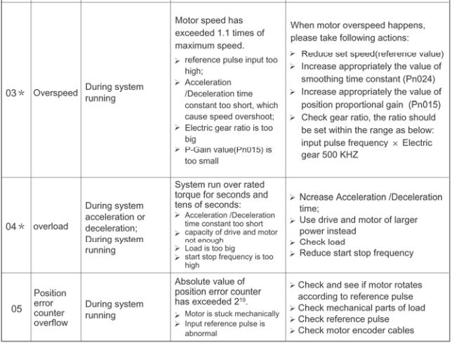
84 Chapter 5 Troubleshooting 5.1 Alarm list A.21* Power loss error A power interruption exceeding one cycle occurred in AC power supply A.25 Watchdog reset System reset by watchdog A.99 〇 Not an error Normal operation status

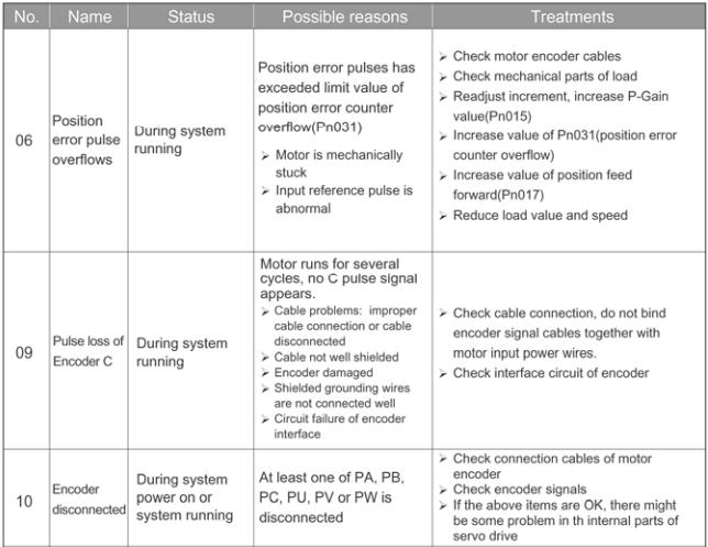
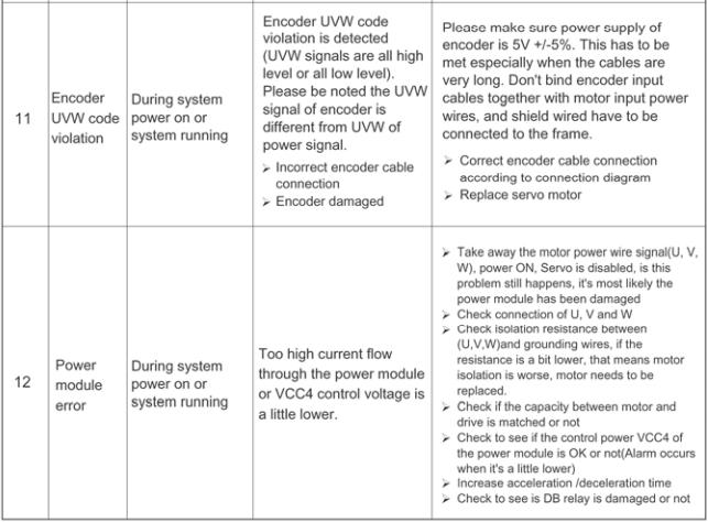
85 5.2 Alarm reasons and Troubleshooting
86 - 86 -
87 - 87 -
88 5.3 Clear alarm Clear current alarm When an alarm occurs, press ENTER for seconds in hand-held panel operator s status display mode, then current alarm is deleted. Besides, the alarm can also be cleared by using 1CN-6(ALM_RST) input signal. Notes: 1. Only current alarms with * sign in 5.2 can be deleted. 2. Eliminate alarm cause first, then input 1CN-6(ALM_RST)signal, current alarm is removed immediately. 3. During effective period of 1CN-6(ALM_RST)signal, motor is in free status, that equals to SERVO OFF status. Clear alarm history In the auxiliary function mode of panel operator, with Fn000, the latest eight (8) alarms can be deleted. Refer to instructions in

89 Chapter 6 Panel Operator 6.1 Basic Function Function description An external panel operator as shown below can be connected to EDC series of servo drives to make parameter setup, status monitoring and auxiliary functions. The description of the keys on the panel operator and their functions are followed by a panel operator on initial display status as an example. Name INC key DEC key MODE key ENTER key Function Press INC key to increase the set value(a long and hold on press will implement fast increasing) Press DEC key to decrease the set value.(a long and hold on press will implement fast decreasing) Press this key to select the status display mode, parameter setup mode, monitor mode, or auxiliary function mode. Press this key to cancel setting when setting the parameters. Press this key to display the parameter settings and set values Reset Servo Alarms In alarm status display mode of the operator, press ENTER key and hold on for seconds to reset current alarm.
90 Refer to 5.1 and clear alarm code. The alarm can also be removed by using 1CN-6(/ALM_RST) input signal. If the power supply is switched OFF due to a servo alarm, then alarm reset operation is not necessary. Note: When any alarm occurs, always remove alarm reasons first before performing alarm reset Display mode selection By toggling among the different basic modes on the panel operator, operations like current running status display and parameter setup can be performed. The operator consists of following basic modes: Status display, Parameter setup, Monitor mode and Auxiliary function mode. Press MODE key to select a display mode in the following order. Power ON Status display mode Parameter setting mode Monitor mode Mode Auxiliary Function
91 6.1.4 Status Display Mode In status display mode, the digits and simple code are used to show the status of servo drive. Selection of Status Display Mode The status display mode is displayed when the power is turned ON. If current mode is not the status display mode, press MODE key to switch to required mode. Contents displayed in Status Display Mode Contents displayed in the mode are different in Position Control Mode and Speed Control Mode. When in Speed Control mode Speed coincidence Digits simple code Standby Control power ON Speed reference being input Rotation detection output Main circuit power supply is ready Torque reference being input Contents of digit display Digit data Description Control power is ON Lamp lights on when control power of servo drive is ON Standby Lamp lights on when servo is on standby; Lamp extinguishes when servo is ON Speed coincidence When offset value between speed reference and actual motor speed is within allowable value, lamp lights on. Allowable value: Pn029 (The standard value is 10 min/r) Rotation detection output Reference speed input is continuing When motor speed exceeds allowable value, lamp is lit. When motor speed is lower than allowable value, lamp goes extinct. Allowable value: 10% of rated speed When reference speed input exceeds allowable value, lamp is lit. When reference speed input is lower than allowable
92 Reference torque input is continuing Main circuit power supply is ready value, lamp goes extinct. Allowable value: 10% of rated speed When reference torque input exceeds allowable value, lamp is lit When reference torque input is lower than allowable value, lamp is extinct. Allowable value: 10% of rated torque Lamp is lit when main circuit power supply is OK; Lamp is extinct when main circuit power supply is OFF. Contents of simple code display Code Meaning On standby; Servo OFF (Servomotor power is OFF) Run Servo ON (motor power is ON) Alarm Blinks the alarm number. When in Position Control mode Speed coincidence Digits simple code Standby Control power ON reference pulse being input Rotation detection output Main circuit power supply is ready Clear signal being input Contents of digit display Digit data Description Control power is ON Lamp lights on when control power of servo drive is ON Standby Lamp lights on when servo is on standby; Lamp extinguishes when servo is ON Speed coincidence When offset value between position reference and actual motor position is within allowable value, lamp lights on. Allowable value: Pn030 (The standard value is
93 Rotation detection output Reference pulse input is continuing Clear signal input is continuing Main circuit power supply is ready pulse) When motor speed exceeds allowable value, lamp is lit. When motor speed is lower than allowable value, lamp goes extinct. Allowable value: 10% of rated speed When reference pulse input is continuing, lamp is lit. When there is no reference pulse input, lamp goes extinct. When clear signal input is continuing, lamp is lit. When there is no clear signal input, lamp goes extinct. Lamp is lit when main circuit power supply is OK; Lamp is extinct when main circuit power supply is OFF. Contents of simple code display: Code Meaning On standby; Servo OFF (motor power is OFF) Running; Servo ON (motor power is ON) Alarm Status The alarm code is displayed Parameter Setting Mode Parameters related to the operation and adjustment of the servomotor are set in this mode. See the Parameter List in Appendix A for details. Change parameters Please see the Parameter List in Appendix A to know exactly the range of parameter change. Following is an operational example of changing the data of Pn 019 from 100 to Press MODE key to select parameter setup mode. 2. Press INC key or DEC key to select parameter number. 3. Press ENTER key to display parameter data selected in step
94 4. Press INC or DEC to change the data to the desired number 85. Hold the button to accelerate the value changing. When the data reaches the Max or Min value, the value will stay unchanged even if INC/DEC key is pressed. 5. Press ENTER, the data glimmers and then the date is saved. 6. Press ENTER again to go back to parameter number display. Plus, if Mode key is pressed during step 3 or step 4, parameter setup operation will go directly to step 6 and no changes will be saved. If the user needs to change any data later, just repeats the operation from step 2 to step 6. If Pn080 needs to be set as , then a decimal point is used on bottom right corner of the top number to show current value is negative. For instance, the value is displayed as below: Monitor Mode The monitor mode can be used for monitoring the external reference values, I/O signal status and internal status of servo drive. User can make changes in Monitor Mode even if motor is running. Following are the operation steps to use Monitor Mode The example as below shows the operation steps for monitoring Data 1500 of Un Press MODE key to select monitor mode. 2.Press INC key or DEC key to select the monitor number to be displayed. 3.Press ENTER to display the monitored data selected in Step 2. 4.Press ENTER again to return to monitor number display
95 Contents of Monitor Mode display Monitor No. Contents Un000 Actual motor speed: r/min Un001 Input speed reference value: r/min Percentage of feedback Un002 torque: % (relative rated torque) Percentage of input Un003 torque: % (relative rated torque) Un004 Number of pulses of Encoder angles Un005 I/O signal monitor Un006 Encoder signal monitor Speed given by pulse Un007 (when electronic gear ratio is 1:1) Un008 Current motor position is 5 digits lower ( 1 pulse) Current motor position is Un009 5 digits higher ( pulse) Position reference is 5 Un010 digits lower ( 1 pulse) Position reference is 5 Un011 digits higher ( pulse) Position offset is 5 digits Un012 lower ( 1 pulse) Position offset is 5 digits Un013 higher ( pulse) Digits to display internal status Notes: 1. Position pulse value is subject to electronic gear ratio of 1:1. 2. Unit of pulse quantity is the internal pulse unit of servo system. Pulse
96 quantity is represented with 5 digits higher + 5 digits lower, whose calculation method is as below: Pulse quantity = value of 5 digits higher value of 5 digits lower Value of pulse quantity will not change any more when it reaches The decimal point at top digit of Un 010, Un 012 and Un 014 means the value is negative. For instance: Un010 is displayed as: It means the value of Un010 is When the speed given by pulse is below electric gear ratio of 1:1, encoder shows the theoretical rotation speed of the gain type 2500 lines of electric motor. 4. Pulse numbers of encoder angles show the rotor s position in relate to stator in one complete revolution, one revolution is regarded as one cycle. 5. As for wire saving encoder motor, its encoder signal only represents the data during power on, the contents of non wire saving encoder signal display is shown in the following table: Monito r No. Un No. of digits I/O Input signal Contents displayed Signal of Encoder W Signal of Encoder V Signal of Encoder U Relevant I/O Signals 2CN-12\13(PG-W) 2CN-5\6(PG-V) 2CN-10\11(PG-U) 6. Contents of I/O terminal signals are in the following table: Monito r No. No. of digits I/O Contents displayed Relevant I/O Signals 0 Input Servo ON 1CN-15 signal (/S-ON) 1 Alarm reset 1CN-6(/ALM_R ST) 2 Clear error counter 1CN-7(/CLR) Un005 Zero position 3 signal 1CN-17(/ZPS) 4,5,6 No display No signal 7 Output Servo alarm 1CN-4 (/ALM) 8 signal Positioning complete(speed achieves) 1CN-3 (/COIN)
97 9 Mechanical braking released 1CN-2 (/BRK) The relative LED is lit to show some I/O signal is active. 6.2 Auxiliary functions In Auxiliary Function Mode, some application operations can be done with the digital operator. The functions details are shown as below: Function No. Content Other Fn000 Display alarm history Fn001 Restore to factory settings Fn002 JOG operation Fn003 Automatic offset-signal adjustment Open operation of motor current detection Fn004 software version of servo Fn005 System runtime Fn006 Software version of panel operator Hidden operation Fn007 Factory test Fn008 Inertia inspection Notes: 1. Open operations refer to the auxiliary functions for general users. 2. Hidden operations: When the panel operator is in simple code menu, press and start to use the auxiliary functions Alarm history display The last ten(10) alarms are displayed in the alarm history library. Take following steps to check the latest alarm. 1. Press MODE key to select auxiliary function mode 2. Press INC or DEC to select function number of alarm history display. 3. Press ENTER key, the latest alarm code is displayed. Alarm No. Alarm code 4. Press INC or DEC key to display other alarm codes occurred recently

98 5. Press ENTER to return to function number display. If an alarm occurs right now, the alarm codes will be updated immediately. The alarm with a serial number of 0 is the current alarm, and the alarm with a serial number of 9 is the last alarm. If the user wants to clear all alarm history data, press ENTER key and hold on for one second while alarm codes are being displayed, then all alarm history is deleted Restore to factory settings This function is used when returning to the factory settings after changing parameter settings. 1. Press MODE key to select auxiliary function mode. 2. Press INC or DEC key to select function number for restoring to factory settings. 3. Press ENTER to enter parameter restoring mode. 4. Press ENTER key and hold on for one second to restore all the parameters to default values. 5. Release ENTER key to return to function number display. 6. In Step 3, the parameter restoring operation can be cancelled and quit current operation by a short press on the ENTER key JOG operation Note: This mode is not available when servo is on or some alarm occurs
.. 4. Press MODE key to enable Servo ON /S-ON.. 5. Press MODE key to turn servo ON and OFF.")
99 Take following operation steps to make JOG operation. 1. Press MODE key to select auxiliary function mode. 2. Press INC or DEC key to select JOG Function number. 3.Press ENTER key to enter JOG mode, meanwhile, servo is OFF(motor power is OFF).. 4. Press MODE key to enable Servo ON /S-ON.. 5. Press MODE key to turn servo ON and OFF. If user wants to run motor, Servo On has to be used. 6. Press INC or DEC key, motor runs when pressing the keys. The servomotor will rotate at the present setting speed as below. During motor s FWD or REV direction, LED display is as below: Forward direction Reverse direction 7. Press ENTER to return to function number display. At this moment, servo motor is turned OFF Automatic offset signals adjustment of motor current detection The servo drive will check motor current detection signals every time the servo is initializing upon power on and will adjust automatically if required, therefore, user needn t do any manual adjustment in normal situations. If the user thinks the torque is a bit too large by judging from motor current offset, user may manually adjust motor current to lower down the torque further or to get higher running accuracy. This section gives a know-how instruction on the operation steps to make offset signal automatic and manual adjustment

100 Note: The offset signal adjustment of motor current detection is only available when servo is OFF. Adjust motor current detection offset signal automatically Take following steps to make automatic offset adjustment. 1. Press Mode key to select auxiliary function mode. 2. Press INC or DEC key to select function number. 3. Press ENTER key and enter automatic adjusting mode. 4. Press MODE and hold on for one second, done is displayed and glimmers, the offset signal is then adjusted automatically. Release the key 5. Press ENTER key to return to function number display Servo software version display Take following steps to display software version of the servo drive. 1. Press MODE key and select Auxiliary Function Mode; 2. Press INC key or DEC key to select function number of software version display. 3. Press ENTER key, current software version is displayed. 4. Press ENTER key again to return to function number display
101 6.2.6 System runtime Take following steps to display system runtime. 1. Press MODE key and select Auxiliary Function Mode 2. Press INC key or DEC key to select function number. 3. Press ENTER key to display system runtime. Following picture shows system runtime is 1 hour and 28 minutes. 4. Press ENTER key again to return to function number display. The displayed time is the runtime after system is started up, the date is not refreshed in real time. If user wants to refresh the data, please repeat the operations in Step 3 and Step Software version of panel operator Activate the hidden functions first before making operations in Section 6.2.7, and Take following steps to display software version of the panel operator. 1. Press MODE key and select Auxiliary Function Mode; 2. Press INC key or DEC key to select function number.. 3. Press ENTER key, current software version is displayed. 4. Press ENTER key again to return to function number display Factory test Inertia inspection Take following steps to make inertia inspection. 1. Press MODE key and select Auxiliary Function Mode; 2. Press INC key or DEC key to select function number
102 3. Press ENTER key and go into inertia inspection page as shown below:. 4. Press Mode key again to start inertia detection. Following page is displayed:. If servo alarm occurs or servo is ON, inertia inspection will not be executed, instead, a message abort is displayed on the panel operator as below. If the user wants to cancel the function during inertia inspection or after entering the function menu, just press ENTER key. 5. When inertia inspection completes, inertia value of load and motor are displayed in the unit of 0.1 Kg m Press ENTER key again to return to function number display page. Notes: 1. Please be very careful during inertia inspection operation, because motor will run forward and reverse for four(4) revolutions, meanwhile, motor is not controlled by external signals. Make sure the running stroke of load is within required range to avoid possible damage to user s equipments. 2. This operation is unavailable if servo is on or servo alarm occurs. Chapter 7 Trial operation 7.1 Inspection and checking before trial operation To ensure safe and correct trial operation, inspect and checking the following items before starting. 1. Wiring All wiring and connections are correct. The correct power supply voltage is being supplied to the main circuit and servomotor. All groundings are good. If trial operation only refers to JOG function, 1CN wiring will not be required. Refer to Check power supply specification and make sure input voltage is correct. 3. Fix servomotor securely Fix servomotor on the base as secure as possible, to avoid the risk of
103 danger which is caused by the counterforce coming from motor speed change. 4. Remove motor load In case servo drive or moving structures are damaged, or indirect person hurt or injury, make sure motor load is removed, including the connector and its accessories on the motor shaft. 7.2 JOG operation No other wiring (such as 1CN)is required for trial JOG operation, it s suggested JOG operation is done with low speed. If motor can run properly in JOG operation, which means motor and servo drive are in good condition, and their connection is correct. If motor cannot run, check connection of UVW and encoder cables. If motor runs improperly, check if the phase order of UVW cables is correct or not. Notes: 1. Before JOG operation, make sure motor load is removed from 1CN. 2. Load default parameters and initializes user parameters to factory settings. 3. Power On again to start trial running. With help of panel operator, follow the steps below and start JOG operation. 1. Turn on servo drive s power supply. Panel operator gives a display as below: 2. Press MODE key. 3. Press MODE key again. 4. Press MODE key a third time to switch onto the menu for auxiliary functions. 5. Press INC key and increase the value to
104 6. Press ENTER key and go into JOG operation mode. 7. Press MODE key and select Servo On. 8. Press INC key, motor runs counterclockwise. Press DEC key, motor runs clockwise. Motor speed depends on Pn032 setting. If the above key is released, motor should stop running. Forward Reverse 9. Press MODE key and select Servo OFF. 10.Press ENTER key and exit JOG operation. 7.3 Trial operation in position control mode 1. Preparation Check if 1CN cable, power cables of servo drive and servomotor, encoder cables are connected in the right way. 2. Operation steps 1) Set Parameter 008 according to output style of servo drive, set Pn041 as 0, then Power On again. 2) When Servo On is enabled(/s-on signal becomes active), motor will keep in excitation status. 3) A low frequency signal is sent from host controller to servo drive, motor is set to run at low speed. 4) Check motor speed with panel operator by its Un000 display, or monitor motor speed with host controller. Make sure feedback speed of servomotor agrees with the setting value. Inspection: When reference pulse stops, motor should stop running. Relation between motor speed and pulse frequency input. Input pulse Motor frequency other frequency(hz) (r/min) pulse+direction

105 500K K K K 300 Electronic gear ratio is 1:1; line number of motor encoder is 2500ppr. Chapter 8 Communication 8.1 RS232 communication hardware structure EDC servo drive supports RS232 communication. Via the RS232 COM function in its front panel, parameters reading out or writing in and system status monitoring are available External connection diagram Following diagram shows external connection between servo drive and PC Cable connection Following illustration shows the plug shape of the RS232 COM port on EDC servo drive. See the signal definition details in the following table: Pitch Signification 1 VCC,internal 5V power supply of servo drive 2 TX,RS232 COM transmission foot
106 3 RX,RS232 COM receiving foot 4 5 GND,grounding of internal power supply of servo drive FG,connect the shield layer of COM to the earth. Following diagram shows how to connect a PC to EDC s COM port. Notes: 1. Depending on different environment situations and communication speeds, effective communication distance also varies. When communication baudrate exceeds 38400bps, a communication cable within one(1) meter long is required to ensure transmission accuracy. 2. Its suggested shielded cables are used for communication, subject to the two shield layers are connected to their own pitches. 3. When external interface is RS422 or RS485, it s required to use external converting module for connection to servo drive. 8.2 Communication relevant parameters When the value 0 is selected as the panel shaft number of EDC servo drive, then servo drive is able to communicate with panel operator and PC via the internal protocol, which has nothing to do with the communication parameters Pn060, Pn061 or Pn062. When the values in the range of 1~E is selected as the panel shaft numbers, MODBUS communication function should also be enabled, then it s available for EDC servo drive to communicate with ESVIEW software. The selected panel shaft number is the communication address. The speed is set according to Pn061 settings, and the communication protocol is set according to Pn
107 settings. Only when the value F is selected as the panel shaft number, shaft number address Pn060 is used by the servo drive. 1 COM address Paramete r Name Unit Setting range Factory setting COM Pn060 1~254 1 address When the dial switch on the drive panel is set as F, this parameter is used as the communication address. 2 COM speed Parameter Name RS232 COM speed Unit Setting rang Factory setting 0 : Pn bit /s 1 : 9600bit /s 2 : 19200b it/s bps 0~2 1 When communication function is used, same communication speed between host controller and servo drive is required. 3 COM protocol Parameter Name RS232 COM protocol Unit Setting rang Factory setting Pn062 0:7,N,2(Modbus, ASCII) 0~
108 1:7,E,1(Modbus, ASCII) 2:7,O,1(Modbus, ASCII) 3:8,N,2(Modbus, ASCII) 4:8,E,1(Modbus, ASCII) 5:8,O,1(Modbus, ASCII) 6:8,N,2(Modbus, RTU) 7:8,E,1(Modbus, RTU) 8:8,O,1(Modbus, RTU) This parameter decides which COM protocol to be used, the number 7 or 8 means digit numbers of data for data transmission is 7 digits or 8 digits. English alphabet N, E and O means odd or even. N means this digit is disabled, E means 1 digit even, O means 1 digit odd, the number 1 or 2 means stop is 1 digit or 2 digits. The communication protocol between host controller and servo drive are required to be the same when communication function is used. 4 COM input IO control When using COM control function, the parameter Pn059 can be used to shield input IO signals if the user does not want external input signals to affect servo
109 drive. When some bit is set as (0)zero, the signal of this bit is then controlled by the external input signal. If the bit is set as 1, then COM control is applied to this bit. Paramet Unit Setting Factory Name er rang setting Pn059 COM input IO control 0~15 0 This parameter is used to set whether the number input of servo drive is controlled by external IO or by COM. When the parameter is set as zero, it means all numerical IO input pitches are controlled by external signals. When it is set as 15, it means all of the four IO inputs are COM controlled, and all external input signals are ignored. Input signal source is decided by value of Pn059: Pn059 Comments on every bit Decides SON ( 1CN-15 ) source of BIT0 signal input: 0:controlled by external input signal 1:controlled by COM Decides ALM-RST(1CN-6)source of BIT1 signal input: 0:controlled by external input signal 1:controlled by COM Decides CLR(1CN-7)source of signal BIT2 input: 0:controlled by external input signal 1:controlled by COM BIT3 Decides ZPS ( 1CN-17 ) source of signal input:
110 0:controlled by external input signal 1:controlled by COM Following are the two ways for COM function to operate on digital input IO signals: 1. Change the value of Pn054 directly, inverts required signal and enables it. 2. Set Pn059 first, to make servo ignore external input signal, then write in corresponding value to the data whose address is 0x00F5 when controlling of external input signal is required. The value of the data whose address is 0x00F5 is not saved after a power interruption. The table below gives an instruction of the value of the data whose address is 0x00F5. Value of data whose address is 0x00F5 Comments on every bit Decides SON(1CN-15)signal: BIT0 0:signal is invalid 1:signal is valid Decides ALM-RST(1CN-6)signal: BIT1 0:signal is invalid,s-off 1:signal is valid Decides CLR(1CN-7)signal: BIT2 0:signal is invalid,s-off 1:signal is valid Decides ZPS(1CN-17)signal: BIT3 0:signal is invalid,s-off 1:signal is valid For example, when COM is used control IO signals of external input, set
111 Pn059 as 15, which means all external digital input IO are controlled by COM. When servo On is required, write in the value 1 to servo drive's 0x00F5 address. 8.3 MODBUS communication protocol When axis number on front panel of EDC servo drive is not selected as zero, MODBUS protocol is used for communication. There're two modes available in MODBUS communication that is ASCII Mode(American Standard Code for information interchange) or RTU(Remote Terminal Unit)mode. See pages below for a simple introduction of these two communication modes Code signification ASCII mode: Each 8-bit data consists of two ASCII characters. Here's an example of a 1-byte data 64H expressed in hex system, if the data is expressed in ASCII mode, it includes ASCII code of 6(36H)and ASCII code of 4(34H). Follow table shows the ASCII code from 0 to 9 and from A to F. Character sign ASCII code 30H 31H 32H 33H 34H 35H 36H 37H Character 8 9 A B C D E F sign ASCII code 38H 39H 41H 42H 43H 44H 45H 46H RTU mode: Each 8-bit data consists of two 4-bit data expressed in hex system. For example, the number 100 in decimal system will be expressed as 64H if RTU data of 1 byte is used. Data structure: 10bit character format( for 7-bit data)
112 11bit character format(for 8-bit data) 8 E 1 Modbus ASCII / RTU Start bit Even parity Stop bit 8-data bits 11- bits character frame 8 O 1 Modbus ASCII / RTU Start bit Odd parity Stop bit 8-data bits 11- bits character frame Communication protocol structure: Data format of communication protocol:
113 ASCII mode: STX Start bit : =>(3AH) ADR CMD End 1 End 0 COM address=>1-byte including two ASCII codes Reference code=>1-byte including two ASCII codes Data contents =>n-word=2n-byte including four ASCII code, no more than 12 Checkout code=>1-byte including two ASCII codes stop bit1=>(0dh)(cr) stop bit0=>(0ah)(lf) RTU mode: STX Freeze time for transmission time of over 4 bytes at current transmission speed ADR COM address=>1-byte CMD DATA(n- 1) DATA(0) LRC DATA(n- 1) DATA(0) CRC End 1 Reference code=>1-byte Data content=>n-word=2n-byte,n is no more than 12 CRC checkout code=>1-byte Freeze time for transmission time of over 4 bytes at current transmission speed See followings for an introduction on data format of COM protocol. STX(COM start) ASCII mode: : byte RTU mode:freeze time for transmission time of over 4 bytes(which varies automatically according to changing of communication speed)
114 ADR(COM address) Range of legal COM address: from 1 to 254 The example below shows communication with a servo whose address is 32, if expressed in hex system the address will be 20. ASCII mode:adr= 2, 0 => 2 =32H, 0 =30H RTU mode:adr=20h CMD(Command reference)and DATA(Data) Data format depends on following command codes: Command code: 03H, when reading N words, maximum value of N is 20. For example, read the first two words from start address 0200H from a servo at the address of 01H. ASCII mode: Reference information: Response information: RTU mode: Reference information: Response information:
 into 01H servo at the")

115 Reference code: 06H, write in one word. For instance, write 100(0064H) into 01H servo at the address of 0200H. ASCII mode: Reference information: Response information: RTU mode: Reference information: Response information:

116 Take following steps to calculate value of LRC(ASCII mode)and CRC (RTU mode). LRC calculation in ASCII mode In ASCII mode, LRC(Longitudinal Redundancy Check) is used. LRC value is calculated according to following way: first make a sum result of the values from ADR to contents of a finishing stroke, then the result is divided by 256, later on, take away the part that goes beyond, after that calculate its fill-in number, final result will be the LRC value. Following example shows the steps to read a word from 01H servo drive at the address of Sum ADR's data from beginning to the last data: 01H+03H+02H+01H+00H01H=08H Take fill-in number of 2 from 08H, therefore LRC is F, 8 CRC calculation in RTU mode

117 CRC(Cyclical Redundancy Check)error detection value is used in RTU mode. Take following steps to calculate CRC error detection value. Step 1: Load in a 16-bit register whose content is FFFFH, which is called CRC register. Step 2: Make OR calculation of the 1 st bit (bit0) of reference information and the low bit (LSB) of 16-bit CRC register, then save the result into CRC register. Step 3: Check lowest (LSB) of CRC register, if this bit is 0, then move the value to the right for one digit. If this bit is 1,then move the value to the right for one digit, after that, make OR calculation with A001H. Step 4: Go back to Step3, when knows Step 3 has been done eight times, moves on to Step5. Step 5: Repeat operations from Step 2 to Step 4 for the next bit of reference information, when knows all bits have been processed in the same way, the wanted CRC error detection value is just the current content in the CRC register. Instruction: After CRC error detection value is calculated, it's required to fill in first the low bit of CRC in reference information, then fill in the high bit of CRC. Refers to the example below. Example: Read two words from 0101H address of 01H servo drive. Final content of CRC register is calculated and turns to be 3794H by summing the date from ADR to last bit, then its reference information is shown below. Please be noticed 94H should be transmitted before 37H. End1 End0(Communication complete) ASCII mode: Communication ends with the character \r carriage return and (0AH) \n new line
118 RTU mode: The freeze time for communication time required by four bytes at a speed exceeding current communication speed means communication comes to an end. For example: Use C language to generate CRC value. This function needs two parameters: unsigned char * data; unsigned char length; This function will transmit back CRC value of unsigned integer. unsigned int crc_chk(unsigned char * data,unsigned char length){ int i,j; unsigned int crc_reg=oxffff; While(length- -){ crc_ reg ^=*data++; for(j=0;j<8;j++){ If(crc_reg & 0x01){ crc_reg=( crc_reg >>1)^0xA001; }else{ crc_reg=crc_reg >>1; } } } } return crc_reg; Communication error handling Error may occur during communication. Normal error sources are as below: When reading and writing parameters, data address is incorrect. When reading parameters, data value is higher than this parameter's maximum value or lower than its minimum value. Communication is disturbed, data transmission error or checking code error. When above communication error occurs, it does not affect running of servo drive, meanwhile, the drive will give a feedback of error frame. The format of error frame is shown in following table. Data frame of host controller: start Slave station address command Data address, references, checkout
119 etc. Servo drive's feedback of error frame: start Slave station Response address code Error code checkout Comments: Error frame response code = Command+80H; Error code=00h:communication is good =01H:servo drive can't identify requested function =02H:given data address in the request does not exist in servo drive =03H:given data in the request is not allowed in servo drive(higher than maximum value or lower than minimum value of the parameter) =04H:servo drive has started processing the request, but unable to finish this request. For example: Let's suppose the axis number of servo drive is 03H, and we want to write data 06H into Parameter Pn002. Because maximum and minimum value of Pn002 are both zero(0), the data which is to be written in will not be accepted, instead, servo drive will feedback an error frame with error code 03. The frame is as below: Data frame of host controller: start Slave station command Data address, address references, etc. 03H 06H 0002H 0006H Servo drive's feedback error frame: start Slave station Response Error code address code 03H 86H 03H checkout checkout Plus, if the slave station address of data frame transmitted by Host
120 controller is 00H, it means this frame of data is broadcasting data, and servo drive will not feedback a frame Parameters, servo status data communication address In MODBUS communication mode, all the communication parameters of EDC servo are shown in the following table: Address of communication data 0000~0078H Meaning Comments Operatio n Parameter area Parameters in corresponding parameter table Readabl e and writable Monitored data 0806~0814H ( consistent with data displayed on handheld operator or drive panel Read only 0806H Speed feedback Unit: r/min read only 0807H Input speed reference value Unit: r/min read only 0808H Percentage of Input torque reference Relatively rated torque read only Percentage of 0809H Internal torque Relatively rated torque read only reference 080AH Pulse number of Encoder rotation read only 080BH input signal status read only 080CH status of encoder signal read only 080DH status of output signal read only 080EH Pulse given read only 080FH Current position low Unit: 1 reference pulse read only 0810H Current position Unit: reference high pulse read only 0811H error pulse counter low 16 position read only
121 0812H 0813H 0814H error pulse counter high 16 position Given pulse counter low Given pulse counter high Unit: 1 reference pulse Unit: reference pulse read only read only read only 0817H Current alarm read only 07F1~07FAH Alarm information storage area 10 History Alarms read only 0900H IO signal of readable No saving in case of Modbus and power interruption Communication writable 0901H Drive status read only 0904H Runtime of servo drive Unit: minute read only 090EH DSP software Version expressed in version number read only 1000H Drive model Host controller reads information from servo drive read only 1021H Reset History Alarm 1022H Reset current alarm 1023H JOG Servo ON 01: Reset 01: Reset 01:enable 00:disable readable and writable readable and writable readable and writable 1024H JOG forward run 01:forward run 00:stop readable and writable 1025H JOG reverse run 01:reverse run 00:stop readable and writable
122 Notes: 1 parameter area(com address is from 0000 to 0078H) Parameters in related parameter table, for example, parameter with 0000H as COM address is expressed as Pn000, parameter with 0065H as COM address is expressed as Pn101, and read-write of data at 0000H is the same as operating on parameterpn000. If data coming from communication is not within the parameter range, the data will be abandoned and servo drive will feedback a message of operation fail. If the parameter is changed successfully, this parameter will be saved automatically after a power interruption. 2 Monitoring data area(0806~0814h) The monitoring data does not correspond totally to display of Un000~Un013on handheld operator. For example, the data that communication reads from address of 0807H is FB16H, then specified speed is r/min. Following table shows the meaning of each monitoring data. Monitore d data Comments 0806H Actual motor speed: r/min 0807H Input speed reference value: r/min Digit of Internal Feedback torque percentage % status 0808H (Relatively rated torque) 0809H 080AH 080BH 080CH 080DH 080EH Input torque percentage % (Relatively rated torque) Encoder angle pulse number input signal monitor Encoder signal monitor Output signal monitor Pulse given speed(when electronic gear ratio is 1:1) 080FH Current motor position is 5 digit low ( 1 pulse) 0810H Current motor position is 5 digit high ( 10000pulse) 0811H position error 5 digit low( 1 pulse)
123 0812H position error 5 digit high( pulse) 0813H Position reference 5 digit low( 1 pulse) 0814H Position reference 5 digit high ( 10000pulse) Monitoring of I/O signals is shown below: Monitorin g No. 080BH Digit IO number Contents Relative IO signal 0 Servo ON 1CN-15 (/S-ON) 1 input alarm reset 1CN-6(/ALM_RST) 2 signal Clear error counter 1CN-7(/CLR) 3 zero position signal 1CN-17(/ZPS) 080DH 0 1 output signal servo alarm positioning complete( speed arrives) 1CN-4 (/ALM) 1CN-3 (/COIN,etc) 2 mechanical brake release 1CN-2 (/BRK,etc) 2 Alarm memory block(07f1~07fah) History Alarm No. 0 Meaning History Alarm 1(Latest alarm) Address 07F1H 1 History Alarm 2 07F2H
124 2 History Alarm 3 07F3H 3 History Alarm 4 07F4H 4 History Alarm 5 07F5H 5 History Alarm 6 07F6H 6 History Alarm 7 07F7H 7 History Alarm 8 07F8H 8 History Alarm 9 07F9H 9 History Alarm 10 07FAH (longest time) 2 Modbus communication IO signal(0900h) Use communication to control input digital IO signals, the data is not saved after power is interrupted. 5 System status(0901h) 1-word shows current system status. The following illustration shows the meaning of each digit. EDC servo drive's default speed is 10% of rated motor speed. 6 Run time(0904h) It means the run time required from servo power on to read this data. It's expressed in decimal system and the unit is minute. If the read data is 00CDH, and it's expressed as 205 in decimal system, then it means current system has run for 3 hours and 25 minutes. 7 DSP Software Version(090EH) DSP software version of servo drive is expressed in numbers. If the read data is 00C9H, and it's expressed as 200 in decimal system, then it means the software version is
125 Notes: 1 After COM address is changed, that is, parameter Pn060 or the dialing switch on drive panel is changed, servo drive will feedback data using current COM address until new COM address is updated and becomes available in around 40ms. 2 After communication speed is changed, that is, parameter Pn061 is changed, servo drive will feedback data using current communication speed until new speed is updated and becomes available in around 40ms. 3 After communication protocol is changed, that is, parameter Pn062 is changed, servo drive will feedback data using current communication protocol until new protocol is updated and becomes available in around 40ms. 4 In RTU communication mode, intervals between data frames are longer than 10ms. Chapter 9 Technical specification and features 9.1 Servomotor Technical specification and features EMS series servomotor specification and model description Rated time: continuous Isolation class: F Vibration class: V15 Withstand voltage: AC1500 V Isolation resistor: 5DC50V 10MΩ (minimum) Protection method: fully-closed, self cooling IP67 (except for shaft opening) Ambient temperature: 0~40 Ambient humidity: 20% to 80% (non-condensing) Excitation: permanent magnet Connection method: direct Mounting: flange mounted EMS type 60 series


126 Motor model EMS- 02AH -Z006 04AH -Z013 Matched drive model 02PS-Z006 EDC- 04PS-Z013 Rated 200 W output 400 Rated N m torque Instantaneo us Peak Torque N m Rated Arms current Rated 3000 rpm speed Max. speed rpm 3600 Rotor inertia Kg m Mechanical 1.52 time ms 1.08 constant Electrical 1.95 time constant ms 2.23 Mess Kg EMS type 80 series Motor model EMH- 05AH -A016 08AH -A024 Matched drive 05PS-A016 model EDC- 08PS-A024 Rated 500 W output


127 Rated 1.59 N m torque 2.39 Instantaneo 4.78 us Peak Torque N m 7.16 Rated 3.14 Arms current 4.71 Rated 3000 rpm speed Max rpm speed Rotor Kg m inertia Mechanic al time constant ms Electrical 2.06 time ms 2.30 constant Mess Kg EMS type 90 series Motor model EMS- 08AH -C024 Matched drive 08PS-C024 model EDC- Rated 750 W output Rated 2.40 N m torque Instantaneo 7.1 us Peak N m Torque Rated Arms

128 current Rated speed Max. speed Rotor inertia Mechanic al time constant Electrical time constant rpm rpm Kg m ms ms Mess Kg Servomotor mounting dimension B A Motor model LA LB LC LE LF L M LZ S LR LL LT A B
129 EMS-02AH -Z00 6 EMS-04AH -Z01 3 EMS-05AH -A01 6 EMS-08AH -A02 4 EMS-08AH -C Φ4.5 Φ4.5 Φ5.5 Φ5.5 Φ6.0 Φ1 4 Φ1 4 Φ1 9 Φ1 9 Φ Servomotor connection diagram Cable specification Motor model Drive model Encoder cable Power cable EMS-02AH -Z006 EDC-04PS-Z00 CMP-ZB26- CDM-ZB18-6 EMS-04AH -Z013 EDC-04PS-Z01 CMP-ZB26- CDM-ZB18-3 EMS-05AH -A016 EDC-05PS-A01 CMP-ZB26- CDM-ZB18-6 EMS-08AH -A024 EDC-08PS-A02 CMP-ZB26- CDM-ZB18-4 EMS-08AH -C024 EDC-08PS-C02 4 CMP-SB26- CDM-SB18- EDC servo drive series and EMJ servo motor series Connection:
 Basic data Speed control mode Operating/ storage 0~55/-20~85 Worki temperature ng Operating/ storage Condi humidity Below 90%RH")
130 9.2 Servo drive Technical specification and model Servo drive model EDC- 01P 02P 05P 08P Applicable servomotor model EMx- 01A 02A 05A 08A + Power supply Single phase AC220V 10 %,50/60Hz 15 Control mode Feedback SVPWM Incremental encoder(2500p/r) Basic data Speed control mode Operating/ storage 0~55/-20~85 Worki temperature ng Operating/ storage Condi humidity Below 90%RH (non-condensing) tion Shock/vibration resistance 4.9m/s 2 /19.6 m/s 2 Structure Base mounted Mass ( approximately) 2kg Speed control range 1:5000 Speed Load Regulation regulatio 0~100%:0.01% below (at rated speed)
131 n Voltage regulation Rated voltage ±10%:0%(at rated speed) Temperature regulation Frequency Characteristics Type 0~40:0.1% below(at rated speed) 250Hz(when J L J M ) SIGN+PULSE train, sin. Pulse phase A and phase B,CCW+CW pulse train Positio n control mode Pulse referen ce Pulse Buffer Pulse Frequency Line driving(+5v level),open collector (+5V +12V +24V level Max. 500Kpps(difference)/ 200 Kpps (collector) I/O signals Built-in functio n Control signals Pulse output signal Sequence control input Sequence control output Dynamic braking Protection COM function LED display CLEAR Phase A, phase B and phase C: line driving output Servo ON, Alarm Reset, error counter clear signal, zero clamp signal. Servo Alarm, positioning complete(speed coincidence), brake release, limiting torque Built-in Power module error, overload, overspeed, voltage error, position error counter overflow, encoder disconnected, parameter damaged, etc. With RS232 interface for communication with host controller's special software, Parameter setting, Run operation and status display can be done in Windows mode. Same functions are enabled using panel operator. Compatible with Modbus communication protocol. CanOpen COM Charge indicator, Power & ALM indicator, five 7 segment tube(on panel operator)
132 9.2.2 Servo drive mounting dimension With cooling fan Without cooling fan Appendix A Parameter list Para. No. Name and Meaning Enable/Disable Servo On input Unit Setting range Factory setting Remar ks signal(/s-on) Pn000 [0] Enable Servo ON input signal(/s-on) [1] Enable internal servo ON 0~
133 Para. No. Name and Meaning Unit Setting range Factory setting Remar ks (/S-ON) Enable/Disable input signal Pn001 prohibited (PN-OT) When 1CN-2 is set as PN-OT signal, limiting direction and enabling are selected according to this parameter. [0]disable input signal prohibited 0~2 0 [1]enable forward run input signal prohibited [2]enable reverse run input signal prohibited Pn002 Reserved 0 0 Select operation upon momentary power interruption [0] Servo alarm output is not Pn003 available(alm) [1] Servo alarm output is available(alm) 0~1 0 Pn004 Pn005 Pn006 Stopping method for servomotor after Servo OFF or alarm occurrence [0] Stop the motor by applying DB (dynamic brake) [1] Stop the motor by coasting [2] Stop the motor by applying DB (dynamic brake), then the motor coasts to a stop [3] Stop the motor by coasting without using DB 0~3 0 Clear error pulse signal is turn ON or not after Servo OFF [0] Turned on 0~1 0 [1] turned off Select rotation direction [0] side view from load of 0~
134 Para. No. Name and Meaning Unit Setting range Factory setting Remar ks servomotor, CCW means forward run [1] side view from load of servomotor, CW means forward run Pn007 Speed control mode selection [0] ADRC control 0~1 0 [1] PI control Pn008 Reference pulse form [0] SIGN + PULSE [1] CW+CCW 0~2 0 [2] Phase A + Phase B ( 4), positive logic Pn009 Reference pulse form [0] does not invert PULSE reference, does not invert SIGN reference [1] does not invert PULSE reference, inverts SIGN reference [2] inverts PULSE reference, 0~3 0 does not invert SIGN reference [3] inverts PULSE reference, inverts SIGN reference Pn010 PG pulse dividing ratio P/R 1~ Pn011 Dividing output phase selection 0~1 0 Pn012 Speed feed forward selection [0] disable - 0~1 0 [1] enable Pn013 Speed loop gain Hz 1~ Pn014 Speed loop integral time constant ms 1~ Pn015 Position loop gain 1/s 1~ Pn016 Speed error r/min 0~300 0 Pn017 Position feed forward % 0~100 0 Pn018 Torque reference filter % 0~ Pn019 Soft start acceleration time ms 0~ Pn020 Soft start deceleration time ms 0~ Pn021 S-shaped acceleration and deceleration time ms 0~ Pn022 Electronic gear ratio 1~
135 Para. No. Name and Meaning Unit Setting range Factory setting Remar ks (numerator) Pn023 Electronic gear ratio (denominator) 1~ Pn024 1 st position reference filter ms 0~ Pn025 Feedback filter ms 0~ Pn026 Forward torque limit % 0~ Pn027 Reverse torque limit % 0~ Pn028 Positioning complete detection filter % 0~500 0 Pn029 Speed coincidence error r/min 0~ Pn030 In position error Reference unit 0~ Pn031 Error counter overflow range 256 reference unit 1~ Pn032 JOG speed r/min 0~ Pn033 reserved 0 0 Pn034 reserved 0 0 Pn035 reserved 0 0 Pn036 reserved 0 0 Pn037 reserved 0 0 Automatic gain adjustment: [0] without automatic gain Pn038 adjustment 0~1 0 [1]after inertia detection, gain is adjusted automatically Pn039 P/PI Switching Terms [0] setting torque [1] error pulse [2] acceleration 0~4 0 [3] motor speed [4] disable mode switch function Pn040 P/PI switching threshold 0~ Pn041 Control mode selection [0] Position control (pulse train reference) [2] position contact control (internal position reference) 0~2 0 [3]Speed control (contact reference) Pn042 Reserved 0 0 Pn043 Waiting time for Servo ON ms 20~
136 Para. Setting Factory Remar Name and Meaning Unit No. range setting ks Pn044 Basic waiting procedure ms 0~ Pn045 Waiting speed for brake signal r/min 10~ Pn046 Waiting time for brake signal ms 10~ Pn047 Position error pulse overflow alarm output [0] disable [1] enable - 0~1 0 Pn048 Run speed of programmed -6000~600 r/min speed Pn049 1CN-2output signal selection 0~3 0 Pn050 1CN-3output signal selection 0~3 1 Pn051 1CN two input signal selection 0~3 0 Pn052 Reserved 0~32 0 Pn053 Input IO signal filter time ms 0~ Pn054 Inverts input signal 0~15 0 Pn055 Inverts output signal 0~7 0 Pn056 2 nd electronic gear numerator 1~ Pn057 Dynamic electronic gear enable 0~1 0 Pn058 reserved 0 0 Pn059 RS232 COM input IO contact control 0~15 0 Pn060 RS232 COM address 1~254 1 RS232 COM baudrate 0:4800bit/s Pn061 1:9600bit/s 2:19200bit/s RS232 COM protocol 0:7,N,2(Modbus, ASCII) bit/s 0~2 1 Pn062 1:7,E,1(Modbus, ASCII) 2:7,O,1(Modbus, ASCII) 3:8,N,2(Modbus, ASCII) 0~8 5 4:8,E,1(Modbus, ASCII) 5:8,O,1(Modbus, ASCII)
137 Para. No. Name and Meaning Unit Setting range Factory setting Remar ks 6:8,N,2(Modbus, RTU) 7:8,E,1(Modbus, RTU) 8:8,O,1(Modbus, RTU) Pn063 CAN COM address 1~127 1 CAN COM baudrate 0:50K 1:100K Pn064 2:125K 3:250K Kbit/s 0~5 2 4:500K 5:1M Pn065 CAN COM selection [0]disable 0~1 0 [1]enable Pn066 Reserved 0 0 Pn067 Reserved 0 0 Pn068 Select cycle run [0]multi-point cycle run 0~1 0 [1]multi-point single run Pn069 Enable/disable P-CON signal as step change signal [0] Enable delay step change 0~1 0 [1] use P-CON signal as step changing signal Pn070 Programming method [0]incremental [1]absolute 0~1 0 Origin searching method Z Y X Pn071 Z=0 : turn off origin search function Z=1: Power on, after the 1 st 0~
138 Para. No. Name and Meaning S-ON, start origin search function automatically. Unit Setting range Factory setting Remar ks Z=2:start origin search function automatically everytime after S-ON. Y=0:Search Pulse C after origin search is done Y=1:don't search Pulse C after origin search is done X=0:forward run origin search ZPS as origin X=1:reverse run origin search ZPS as origin Pn072 Start point of program 0~7 0 Pn073 End point of program 0~7 1 Speed 1 when searching Pn074 Pn075 reference point ( hit STROKE /travel distance switch) Speed 3 when searching reference point ( away from STRKE/travel distance switch) r/min 0~ r/min 0~300 5 Pn076 reserved 0~300 0 Pn077 Cycle number of origin search offset 4 10 reference pulse Pn078 Pulse number of origin search offset 1 pulse Pn079 Reserved 0 0 Pn080 moving distance 0 revolutions 4 10 reference pulse ~
139 Para. No. Name and Meaning Pn081 moving distance 0 Unit 1reference pulse Setting range -9999~999 9 Factory setting 0 Remar ks Pn082 Pn083 moving distance 1 revolution moving distance 1 low 4 10 referenc e pulse 1 reference pulse ~ ~ Pn084 moving distance 2 revolutions Pn085 moving distance 2 low 4 10 reference pulse 1 reference pulse ~ ~ Pn086 moving distance 3 revolutions Pn087 moving distance 3 low 4 10 reference pulse 1 reference pulse ~ ~ Pn088 moving distance 4 revolutions Pn089 moving distance 4 low 4 10 reference pulse 1 reference pulse ~ ~ Pn090 moving distance 5 revolutions Pn091 moving distance 5 low 4 10 referenc e pulse 1 reference pulse ~ ~ Pn092 moving distance 6 revolutions Pn093 moving distance 6 low 4 10 referenc e pulse 1 reference pulse ~ ~ Pn094 moving distance 7 revolutions 4 10 referenc ~ e pulse Pn095 moving distance 7 low 1reference -9999~999 pulse 9 0 Pn096 moving distance 0speed r/min 0~ Pn097 moving distance 1speed r/min 0~
140 Para. Setting Factory Remar Name and Meaning Unit No. range setting ks Pn098 moving distance 2speed r/min 0~ Pn099 moving distance 3speed r/min 0~ Pn100 moving distance 4speed r/min 0~ Pn101 moving distance 5speed r/min 0~ Pn102 moving distance 6speed r/min 0~ Pn103 moving distance 7speed r/min 0~ moving distance 0 first(1st) Pn104 acceleration/deceleration time ms 0~ constant moving distance 1 first(1st) Pn105 acceleration/deceleration time ms 0~ constant moving distance 2 first(1st) Pn106 acceleration/deceleration time ms 0~ constant moving distance 3 first(1st) Pn107 acceleration/deceleration time ms 0~ constant moving distance 4 first(1st) Pn108 acceleration/deceleration time ms 0~ constant moving distance 5 first(1st) Pn109 acceleration/deceleration time ms 0~ constant moving distance 6 first(1st) Pn110 acceleration/deceleration time ms 0~ constant moving distance 7 first(1st) Pn111 acceleration/deceleration time ms 0~ constant Pn112 moving distance 0stop time 50ms 0~ Pn113 moving distance 1stop time 50ms 0~ Pn114 moving distance 2stop time 50ms 0~ Pn115 moving distance 3stop time 50ms 0~ Pn116 moving distance 4stop time 50ms 0~ Pn117 moving distance 5stop time 50ms 0~ Pn118 moving distance 6stop time 50ms 0~ Pn119 moving distance 7stop time 50ms 0~ Pn120 Current feed forward compensation 0~

141 Note: After changing the setting, always turn the power OFF, then Power ON again. This makes the new setting valid. The parameter may vary for motors of different models. Appendix B Alarm list A.21* Power loss error A power interruption exceeding one cycle occurred in AC power supply A.25 Watchdog reset System reset by watchdog A.99 〇 Not an error Normal operation status 〇 :Photo-coupler is ON(ON) :Photo-coupler is OFF (OFF) *:Alarm can be deleted
EDC Series AC servo system
 EDC Series AC servo system User s Manual Operation of Version V. 2.20 Troubleshooting Preface This manual describes the operation of the Estun servo drive type EDC and is meant for operators who are instructed
PKG-EMJ08-EDC08-CBLS System Diagram and Specifications
 PKG-EMJ08-EDC08-CBLS System Diagram and Specifications Included Components: EMJ-08APA22 AC Servo Motor EDC-08APE Servo Driver CDM-JB18-05 Power Cable CMP-JB26-05 Encoder Cable EDC-CSC-CC24A-02 Comm Cable
EDB series AC servo system
 EDB series AC servo system User s Manual V. 2.00 Estun Limited Warranty This manual does not entitle you to any rights. Estun reserves the right to change this manual without prior notice. All rights reserved.
PKG-EML10-EDB10-CBLS System Diagram and Specifications
 PKG-EML10-EDB10-CBLS System Diagram and Specifications Included Components: EML-10APA22 AC Servo Motor EDB-10AMA Servo Driver BDM-GA16-05 Power Cable BMP-GA24-05 Encoder Cable EDB-BSC-CC24A Comm Cable
DS2 series servo drive
 DS2 series servo drive Manual WUXI XINJE ELECTRIC CO., LTD. Data No.: SC209 20110412 1.0 2 Safety notes Confirmation Do not use the drivers that are broken, lack of parts or wrong types. Installation Make
DS2 series 220V servo driver
 DS2 series 220V servo driver Fast reference manual Xinje Electronic Co.,Ltd. Serial NO.SC209 20120312 1.0 2 DS2 series 220V servo driver user manual Safety caution Confirmation when receive products DO
EDC Quick Start Guide
 EDC Quick Start Guide BASIC FUNCTIONS This guide will familiarize the user with the basic functions of the EDC Servo Drive and assist with start up. The guide will cover the following: 1. Restoring Parameters
DS2 series servo drive
 DS2 series servo drive User manual WUXI XINJE ELECTRIC CO., LTD. Serial No. SC2 00 20160526 1.0 All copyrights reserved by WUXI XINJE ELECTRIC CO., LTD. Any copying, transferring or any other usage is
Maxsine AC SERVO. EP100 QuickGuide. Maxsine Electric Co.,Ltd
 Maxsine EP100 QuickGuide AC SERVO Maxsine Electric Co.,Ltd 1.1 Standard wiring Position control Maxsine EP100(B) SERVO DRIVER SERVOMOTOR 3 Phase AC220V NFB MC PE R S T r CN2 U V W PE 14 5V 2 3 4 1 4 Pins
K2 系列 AC Servo Driver User s Manual
 K2 系列 AC Servo Driver User s Manual 2015 V1.0 http://www.acservomotor-xl.com Preface Thank you for purchasing this AC servo driver. This Manual is the user manual for K2 series products. To use this series
Series SGMBH/SGDH USER S MANUAL AC Servodrive (400 V, 22 to 55 kw) SGMBH Servomotor SGDH SERVOPACK
 SGMBH Servomotor SGDH SERVOPACK") Series SGMBH/SGDH USER S MANUAL AC Servodrive (400 V, 22 to 55 kw) SGMBH Servomotor SGDH SERVOPACK YASKAWA YASKAWA MANUAL NO. SIE-S800-32.4 Copyright 2002 YASKAWA ELECTRIC CORPORATION All rights reserved.
Series SGMBH/SGDH USER S MANUAL AC Servodrive (400 V, 22 to 55 kw) SGMBH Servomotor SGDH SERVOPACK YASKAWA YASKAWA MANUAL NO. SIE-S800-32.4 Copyright 2002 YASKAWA ELECTRIC CORPORATION All rights reserved.
(For Rotary Servomotors)
") MECHATROLINK-III Communications Reference SERVOPACKs SGDV- E2 (For Rotary Servomotors) Designations S G D V - 2R9 E 2 A 002 00 0 v Series SGDV SERVOPACKs with DC Power Input st+2nd+ 3rd digits 4th digit
MECHATROLINK-III Communications Reference SERVOPACKs SGDV- E2 (For Rotary Servomotors) Designations S G D V - 2R9 E 2 A 002 00 0 v Series SGDV SERVOPACKs with DC Power Input st+2nd+ 3rd digits 4th digit
User Manual. Serial No. SC
 DS2 Series Servo Driver User Manual Xinje Electronic Co., Ltd. Serial No. SC01 20090706 1.0 DS2 Series Servo Driver User Manual Safety Precautions Content Preface Checking Product and Part Names Installation
For more information on these functions and others please refer to the PRONET-E User s Manual.
 PRONET-E Quick Start Guide PRONET-E Quick Start Guide BASIC FUNCTIONS This guide will familiarize the user with the basic functions of the PRONET-E Servo Drive and assist with start up. The descriptions
Analog monitor cable. Filter Motion control unit. General purpose cable. (Refer to chapter Sigma-II rotary motors) Cables SGMGH, SGMUH, SGMSH, SGMBH
 Cables SGMGH, SGMUH, SGMSH, SGMBH") CHARGE NS A R C N B C N 4 XD-@, XD-@-E Intelligent servo drive. Integrated controller and network connectivity. NCT. Patented non-linear algorithm for tight control Very low tracking error with no overshoot
CHARGE NS A R C N B C N 4 XD-@, XD-@-E Intelligent servo drive. Integrated controller and network connectivity. NCT. Patented non-linear algorithm for tight control Very low tracking error with no overshoot
Series SGDH Indexer Application Module USER'S MANUAL
 YASKAWA Series SGDH Indexer Application Module USER'S MANUAL MODEL: JUSP-NS600 YASKAWA MANUAL NO. SIE-C718-9 Copyright 2002 YASKAWA ELECTRIC CORPORATION All rights reserved. No part of this publication
Copyright 2014 YASKAWA ELECTRIC CORPORATION All rights reserved. No part of this publication may be reproduced, stored in a retrieval system, or
 Copyright 2014 YASKAWA ELECTRIC CORPORATION All rights reserved. No part of this publication may be reproduced, stored in a retrieval system, or transmitted, in any form, or by any means, mechanical, electronic,
Troubleshooting Alarm Displays Warning Displays
 10 10.1 Alarm Displays............................................10-2 10.1.1 List of Alarms...................................................... 10-2 10.1.2 of Alarms............................................
Committed to Premium Quality. AC Servo System Catalog
 Committed to Premium Quality AC Servo System Catalog Company Profile CONTENTS DB100 Series AC Servo System 03 Application fields 04 Servo Driver Product Description 05 Servo Motor Product Description 07
General-Purpose AC Servo. MELSERVO-JE Servo amplifier INSTRUCTION MANUAL (TROUBLE SHOOTING)
") General-Purpose AC Servo MELSERVO-JE Servo amplifier INSTRUCTION MANUAL (TROUBLE SHOOTING) F Safety Instructions Please read the instructions carefully before using the equipment. To use the equipment
General-Purpose AC Servo MELSERVO-JE Servo amplifier INSTRUCTION MANUAL (TROUBLE SHOOTING) F Safety Instructions Please read the instructions carefully before using the equipment. To use the equipment
General-Purpose AC Servo. MELSERVO-JE Servo amplifier INSTRUCTION MANUAL (TROUBLE SHOOTING)
") General-Purpose AC Servo MELSERVO-JE Servo amplifier INSTRUCTION MANUAL (TROUBLE SHOOTING) B Safety Instructions Please read the instructions carefully before using the equipment. To use the equipment
General-Purpose AC Servo MELSERVO-JE Servo amplifier INSTRUCTION MANUAL (TROUBLE SHOOTING) B Safety Instructions Please read the instructions carefully before using the equipment. To use the equipment
MSS-D - AC SERVO SYSTEMS
 MSS-D - AC SERVO SYSTEMS USER MANUAL (V1.11) MasterDrive Contents HOW TO READ THE PARAMETERS?... 6 SAFETY NOTICE... 7 CHAPTER 1 PRODUCT INTRODUCTION... 11 1.1 PRODUCT INSPECTIONS... 11 1.2 PRODUCT MODEL
General-Purpose AC Servo. MELSERVO-JE Servo amplifier INSTRUCTION MANUAL (TROUBLE SHOOTING)
") General-Purpose AC Servo MELSERVO-JE Servo amplifier INSTRUCTION MANUAL (TROUBLE SHOOTING) D Safety Instructions Please read the instructions carefully before using the equipment. To use the equipment
General-Purpose AC Servo MELSERVO-JE Servo amplifier INSTRUCTION MANUAL (TROUBLE SHOOTING) D Safety Instructions Please read the instructions carefully before using the equipment. To use the equipment
SGDV- 01 SGDV- 05. Analog Voltage/Pulse Train Reference Type SERVOPACKs. (For Rotary Servomotors) (For Linear Servomotors)
 (For Linear Servomotors)") Analog Voltage/Pulse Train Reference Type PACKs SGDV- 0 (For Rotary Servomotors) SGDV- 0 (For Linear Servomotors) Model Designations S G D V - R70 A 0 A 000 00 0 v Series SGDV PACK st+nd+ rd digits th
Analog Voltage/Pulse Train Reference Type PACKs SGDV- 0 (For Rotary Servomotors) SGDV- 0 (For Linear Servomotors) Model Designations S G D V - R70 A 0 A 000 00 0 v Series SGDV PACK st+nd+ rd digits th
CL86T. 24~80VDC, 8.2A Peak, Closed-loop, No Tuning. Descriptions. Closed-loop. Stepper. Applications. Datasheet of the Closed-loop Stepper CL86T
 CL86T Closed-loop Stepper 24~80VDC, 8.2A Peak, Closed-loop, No Tuning Closed-loop, eliminates loss of synchronization Broader operating range higher torque and higher speed Reduced motor heating and more
ies-2309 Integrated Easy Servo
 Datasheet of the integrated easy servo motor ies-09 ies-09 Integrated Easy Servo Motor + Drive + Encoder, 0-0VDC, NEMA, 0.9Nm Features Easy servo control technology to combine advantages of open-loop stepper
Integrated Easy Servo
 ies 1706 Integrated Easy Servo Motor + Drive + Encoder, 18 32VDC, NEMA17, 0.6Nm Features Easy servo control technology to combine advantages of open loop stepper systems and brushless servo systems Closed
HA-520 Series Technical Manual
 AC Servo Driver HA-520 Series Technical Manual Thank you very much for your purchasing our HA-520 series servo driver. Be sure to use sufficient safety measures when installing and operating the equipment
Troubleshooting 12. This section explains the items to check when problems occur, and troubleshooting by the use of error displays or operation state.
 Troubleshooting 12 This section explains the items to check when problems occur, and troubleshooting by the use of error displays or operation state. 12-1 Actions for Problems..........................................
HSD2 Series Servo Drive User Manual
 HSD2 Series Servo Drive User Manual HNC Electric Limited I Thank you for purchasing our HSD2 AC servo drives. HSD2 Series AC Servo Drive This manual provides the related information about product installation,
Ambient Conditions Storage Conditions Installation Minimum Clearances and Air Flow...2 3
 CHAPTER INSTALLATION 2 AND WIRING Contents of this Chapter... Ambient Conditions..............................2 2 Storage Conditions...............................2 2 Installation.....................................2
AZ Series. Function Edition. Closed Loop Stepping Motor and Driver Package. Operation. I/O signals. Parameter
 HM-6262 Closed Loop Stepping Motor and Driver Package Operation I/O signals Parameter AZ Series Function Edition Method of control via Modbus RTU (RS-485 communication) Method of control via industrial
ES86 Series Closed-loop Stepper Drive + Motor System (Drive+ Motor/Encoder)
") ES86 Series Closed-loop Stepper Drive + Motor System (Drive+ Motor/Encoder) Traditional stepper motor drive systems operate open loop providing position control without feedback. However, because of this,
ES86 Series Closed-loop Stepper Drive + Motor System (Drive+ Motor/Encoder) Traditional stepper motor drive systems operate open loop providing position control without feedback. However, because of this,
DORNA EPS-B2 SERIES USER MANUAL AC SERVO SYSTEMS (V1.05) 1
 1") DORNA AC SERVO SYSTEMS EPS-B2 SERIES USER MANUAL (V1.05) http://en.dorna.com.cn 1 Contents HOW TO READ THE PARAMETERS?... 6 SAFETY NOTICE... 7 CHAPTER 1 PRODUCT INTRODUCTION... 11 1.1 PRODUCT INSPECTIONS...
DORNA AC SERVO SYSTEMS EPS-B2 SERIES USER MANUAL (V1.05) http://en.dorna.com.cn 1 Contents HOW TO READ THE PARAMETERS?... 6 SAFETY NOTICE... 7 CHAPTER 1 PRODUCT INTRODUCTION... 11 1.1 PRODUCT INSPECTIONS...
DORNA EPS-B1 SERIES USER MANUAL AC SERVO SYSTEMS (V1.11) 1
 1") DORNA AC SERVO SYSTEMS EPS-B1 SERIES USER MANUAL (V1.11) http://en.dorna.com.cn 1 Contents HOW TO READ THE PARAMETERS?... 6 SAFETY NOTICE... 7 CHAPTER 1 PRODUCT INTRODUCTION... 11 1.1 PRODUCT INSPECTIONS...
DORNA AC SERVO SYSTEMS EPS-B1 SERIES USER MANUAL (V1.11) http://en.dorna.com.cn 1 Contents HOW TO READ THE PARAMETERS?... 6 SAFETY NOTICE... 7 CHAPTER 1 PRODUCT INTRODUCTION... 11 1.1 PRODUCT INSPECTIONS...
USER'S MANUAL. Series SGMBH/SGDM/SGDH YASKAWA. AC Servodrive (200 V, 22 to 37 kw) (400 V, 22 to 55 kw) SGMBH Servomotor SGDM/SGDH SERVOPACK YASKAWA
 (400 V, 22 to 55 kw) SGMBH Servomotor SGDM/SGDH SERVOPACK YASKAWA") Series SGMBH/SGDM/SGDH USER'S MANUAL AC Servodrive (200 V, 22 to 37 kw) (400 V, 22 to 55 kw) SGMBH Servomotor SGDM/SGDH SERVOPACK YASKAWA YASKAWA MANUAL NO. SIE-S800-32.4B Copyright 2002 YASKAWA ELECTRIC
Series SGMBH/SGDM/SGDH USER'S MANUAL AC Servodrive (200 V, 22 to 37 kw) (400 V, 22 to 55 kw) SGMBH Servomotor SGDM/SGDH SERVOPACK YASKAWA YASKAWA MANUAL NO. SIE-S800-32.4B Copyright 2002 YASKAWA ELECTRIC
Troubleshooting Alarm Displays Warning Displays
 9 9.1 Alarm Displays..............................................9-2 9.1.1 List of Alarms........................................................ 9-2 9.1.2 of Alarms..............................................
Sigma FSP Amplifier User s Manual
 Sigma FSP Amplifier User s Manual Copyright 2006 by YEA, Yaskawa Electric America, Inc. FSP Amplifier User s Manual Catalog No.YEA-SIA-FSP-3, Revision 0 December, 2006 All rights reserved. No part of this
SGDH Amplifier. Part Number Guide. Quick Reference Guide. Amplifier: SGDH - 15 A E- Motor: SGMGH - 09 A C A 6 C $10
 Quick Reference Guide SGDH Amplifier $ Document TRM--SGEN 9// V..4 Yaskawa Electric America Technical Training Services Part Number Guide Norman Dr. South Waukegan, IL 685-8-YASKAWA Fax: (847) 887-785
RDrive 85 servo motors. User manual
 INTRODUCTION Rozum Robotics has designed its RDrive (RD) servo motors to enable precision motion control in industrial and commercial applications. This manual is intended for technicians and engineers
ES86 Series Closed-loop Stepper Drive + Motor System (Drive+ Motor/Encoder)
") ES86 Series Closed-loop Stepper Drive + Motor System (Drive+ Motor/Encoder) Traditional stepper motor drive systems operate open loop providing position control without feedback. However, because of this,
ES86 Series Closed-loop Stepper Drive + Motor System (Drive+ Motor/Encoder) Traditional stepper motor drive systems operate open loop providing position control without feedback. However, because of this,
Series SGDH Indexer Application Module USER'S MANUAL
 YASKAWA Series SGDH Indexer Application Module USER'S MANUAL MODEL: JUSP-NS600 YASKAWA MANUAL NO. SIE-C718-9B Copyright 2002 YASKAWA ELECTRIC CORPORATION All rights reserved. No part of this publication
Engineering Data AC Servo Drive HA-680
 Engineering Data AC Servo Drive HA-680 QUICKLINK www.harmonicdrive.de/1110 SAFETY GUIDE For FHA series, RSF series, HA series Read this manual thoroughly before designing the application, installation,
This section is specifically about safety matters
 6 4 ) 5 1 5 6 4 1 -, 1 8-4 6-4 1 5 6 4 7 + 6 1 ) 7 ) 5 2 - -,, - 6 - + 6 4. 4. 2 J E? A Thank you for choosing this Mitsubishi transistorized Inverter option. This instruction manual gives handling information
Analog Voltage/Pulse Train Reference Type SERVOPACKs. (For Rotary Servomotors) (For Linear Servomotors) SGDV - R70 A 01 B
 (For Linear Servomotors) SGDV - R70 A 01 B") Analog Voltage/Pulse Train Reference Type SERVOPACKs SGDV- 0 (For Rotary Servomotors) SGDV- 05 (For Linear Servomotors) Model Designations SGDV - R70 A 0 B 002000 Options 002000 Base-mounted, varbish(standard)
Analog Voltage/Pulse Train Reference Type SERVOPACKs SGDV- 0 (For Rotary Servomotors) SGDV- 05 (For Linear Servomotors) Model Designations SGDV - R70 A 0 B 002000 Options 002000 Base-mounted, varbish(standard)
4th digit. 7th digit. digits. Specifications. Interface. MECHATROLINK-2 communications Reference Type (for rotary servomotors)
") MECHATROLINK- Communications Reference Type PACKs SGDV- (For Rotary Servomotors) SGDV- 5 (For Linear Servomotors) Model Designations S G D V - R70 A A 000 00 0 v Series SGDV PACK st+nd+ rd digits 4th digit
MECHATROLINK- Communications Reference Type PACKs SGDV- (For Rotary Servomotors) SGDV- 5 (For Linear Servomotors) Model Designations S G D V - R70 A A 000 00 0 v Series SGDV PACK st+nd+ rd digits 4th digit
Supply voltage Output configuration Resolution (P/R) Model 12 to 24 VDC Complementary output 100, 200, 360, 500, or 600 E6F-CWZ5G 1,000
 Model 12 to 24 VDC Complementary output 100, 200, 360, 500, or 600 E6F-CWZ5G 1,000") Incremental 60-mm-dia. Rotary Encoder E6F-C The Strongest Shaft for Tough Jobs The strongest shaft of any OMRON Incremental Encoder (120 N in the radial direction and 50 N in the thrust direction). Water-
Incremental 60-mm-dia. Rotary Encoder E6F-C The Strongest Shaft for Tough Jobs The strongest shaft of any OMRON Incremental Encoder (120 N in the radial direction and 50 N in the thrust direction). Water-
Sigma II Series Servo System User s Manual
 Sigma II Series Servo System User s Manual WARNING YASKAWA manufactures component parts that can be used in a wide variety of industrial applications. The selection and application of YASKAWA products
AC SERVO DRIVES SERIES. Servopacks. Certified for ISO9001 and ISO14001
 AC SERVO DRIVES SERIES Servopacks Certified for ISO9001 and ISO14001 JQA-0422 JQA-EM0202 CONTENTS SERVOPACKs Single-axis Analog Voltage/Pulse Train Reference SERVOPACKs 326 Single-axis MECHATROLINK-II
Indexer unit JUSP-NS600. System configuration. Smart and simple positioning solution.
 Smart and simple positioning solution. No programming languages are required. Connects directly to the drive Allows serial network control and discrete I/O control Servo axis set-up, actuation and monitoring
TRANSISTORIZED INVERTER -INSTRUCTION MANUAL- ORIENTATION CONTROL / ENCODER FEEDBACK CONTROL / PULSE TRAIN INPUT FR-A5AP
 TRANSISTORIZED INVERTER -INSTRUCTION MANUAL- ORIENTATION CONTROL / ENCODER FEEDBACK CONTROL / PULSE TRAIN INPUT FR-A5AP Thank you for choosing the Mitsubishi transistorized inverter option unit. This instruction
30-80V, 8.2A Peak, No Tuning, Nulls loss of Synchronization
 2-phase Hybrid Servo Drive 30-80V, 8.2A Peak, No Tuning, Nulls loss of Synchronization Closed-loop, eliminates loss of synchronization Broader operating range higher torque and higher speed Reduced motor
User manuel. Hybrid stepper servo drive
 User manuel Hybrid stepper servo drive 1 Overview Hybridstepper servo drive system integrated servo control technology into the digital step driver. It adopts typical tricyclic control method which include
Integrated Servo Motor UCS57
 Integrated Servo Motor Introduction is a new generation of high performance digital integrated servo drive motor, which is a series of low voltage AC servo products integrated with AC servo motor and drive
ES86 Series Closed-loop Stepper Drive + Motor System (ES-D808 Drive+ Motor/Encoder)
") ES86 Series Closed-loop Stepper Drive + Motor System (ES-D808 Drive+ Motor/Encoder) Traditional stepper motor drive systems operate open loop providing position control without feedback. However, because
ES86 Series Closed-loop Stepper Drive + Motor System (ES-D808 Drive+ Motor/Encoder) Traditional stepper motor drive systems operate open loop providing position control without feedback. However, because
DCS Series Brush DC Servo Drive. Datasheet
 DCS Series Brush DC Servo Drive Datasheet Version DCS-2014-01 http://www.primopal.com DCS series Brush DC Servo Drives Description PrimoPal s DCS series Brush DC Servo Drive are fully digital brushed servo
ProNet Series AC Servo User's Manual
 ProNet Series AC Servo User's Manual (Version:V2.04) ESTUN AUTOMATION TECHNOLOGY CO., LTD Revision History Date Rev. No. Section Revised Content Remark 2009-09 V1.00~V1.05 - First edition 2010-02 V1.06
(For Linear Servomotors) S G D V - R70 A 21 A th digit. 7th digit. 5th6th digits
 S G D V - R70 A 21 A th digit. 7th digit. 5th6th digits") MECHATROLINK- Communications Reference Type PACKs SGDV- (For Rotary Servomotors) SGDV- 5 (For Linear Servomotors) Designations S G D V - R70 A A 000 00 0 v Series SGDV PACK st+nd+ rd digits 4th digit 5th6th
MECHATROLINK- Communications Reference Type PACKs SGDV- (For Rotary Servomotors) SGDV- 5 (For Linear Servomotors) Designations S G D V - R70 A A 000 00 0 v Series SGDV PACK st+nd+ rd digits 4th digit 5th6th
ProNet Series AC Servo User's Manual. (Version:V2.20)
") (Version:V2.20) Revision History Date Rev. No. Section Revised Content Remark 2009-09 V1.00~V1.05 - First edition 2010-02 V1.06 All chapters Completely revised 2010-06 V1.07 Appendix A 4.6.5 1 Revision:
(Version:V2.20) Revision History Date Rev. No. Section Revised Content Remark 2009-09 V1.00~V1.05 - First edition 2010-02 V1.06 All chapters Completely revised 2010-06 V1.07 Appendix A 4.6.5 1 Revision:
Installation Servo Drive Dimensions
 Installation Servo Drive Dimensions A B Model R88D WTA3H WTA5H A 55 160 130 50 8 149 75 5 0.8 4 1.25 WT01H WT02H WT04H A 75 160 130 63 8 149.5 75 5 1.1 8 2 WT08HH A 90 160 180 63 8 149.5 75 5 1.7 11 2
ADJUSTABLE SPEED DRIVES. AS1 Drive
 ADJUSTABLE SPEED DRIVES AS1 Drive Toshiba s New ASD Product Line The AS1 drive builds on Toshiba s history of supplying powerful, reliable, and versatile drives. We have combined our best drive features
XtraDrive (XD-) SERIES AC SERVO DRIVER
 SERIES AC SERVO DRIVER") XtraDrive (XD-) SERIES AC SERVO DRIVER Prior to installing the product, read these instructions thoroughly and retain for future reference. Short Form Installation Guide Catalog No. 8U0107 Revision B Introduction
XtraDrive (XD-) SERIES AC SERVO DRIVER Prior to installing the product, read these instructions thoroughly and retain for future reference. Short Form Installation Guide Catalog No. 8U0107 Revision B Introduction
This section is specifically about safety matters
 6 4 ) 1 6 4 1 -, 1 8-4 6-4 1 6 4 7 + 6 1 ) 7 ) 4 ) 6 1-6 6-4. 4. 0 J E? A Thank you for choosing this Mitsubishi transistorized Inverter option. This instruction manual gives handling information and precautions
VECTOR INVERTER -INSTRUCTION MANUAL- POSITION CONTROL FR-V5AP
 VECTOR INVERTER -INSTRUCTION MANUAL- POSITION CONTROL FR-V5AP Thank you for choosing the Mitsubishi vector inverter option unit. This instruction manual gives handling information and precautions for use
About this Manual: Chapter 1 provides a summary of the Servo System and all gains used for the Servo System loops.
 About this Manual: This guide describes the installation and startup procedures of the Servo System so that it can be efficiently put in actual operation in a short time. This guide provides detailed descriptions
USER S MANUAL. OMNUC U SERIES MODELS R88M-U (AC Servo Motors) MODELS R88D-UT (AC Servo Drivers) AC SERVO MOTORS/DRIVERS (1 to 5 kw)
 MODELS R88D-UT (AC Servo Drivers) AC SERVO MOTORS/DRIVERS (1 to 5 kw)") USER S MANUAL OMNUC U SERIES MODELS R88M-U (AC Servo Motors) MODELS R88D-UT (AC Servo Drivers) AC SERVO MOTORS/DRIVERS (1 to 5 kw) Thank you for choosing this OMNUC U-series product. Proper use and handling
USER S MANUAL OMNUC U SERIES MODELS R88M-U (AC Servo Motors) MODELS R88D-UT (AC Servo Drivers) AC SERVO MOTORS/DRIVERS (1 to 5 kw) Thank you for choosing this OMNUC U-series product. Proper use and handling
815-BR SERVO AMPLIFIER FOR BRUSH SERVOMOTORS
 815-BR SERVO AMPLIFIER FOR BRUSH SERVOMOTORS USER GUIDE September 2004 Important Notice This document is subject to the following conditions and restrictions: This document contains proprietary information
Two-phase Digital Stepper Motor Driver SD Low Vibration Low Noise Low Power. Characteristics. Performance Index. Product Codes:
 Two-phase Digital Stepper Motor Driver SD-20403 Product Codes: 001700 Low Vibration Low Noise Low Power Characteristics 32-bit DSP digital control mode Low vibration. low noise. low power Flexible micro-stepping,
DOOSAN SEQUENTIAL 2 AXES AC SERVO MOTOR & DRIVE VISION DVSC - TX Series
 NO.300421-00001 DOOSAN SEQUENTIAL 2 AXES AC SERVO MOTOR & DRIVE VISION DVSC - TX Series L: 0.8KW/1.5KW/2.0KW/2.3KW Operation Manual REV. B DOOSAN INFRACORE Version History Ver. Changed Contents Ver. B
4th digit. 5th+6th digits. 7th digit. Specifications. 8th+9th+10th digits Options (hardware)* 4. Interface
* 4. Interface") MECHATROLINK- Communications Reference Type PACKs SGDV- (For Rotary Servomotors) SGDV- 5 (For Linear Servomotors) Designations S G D V - R70 A A 000 00 0 v Series SGDV PACK st+nd+ rd digits 4th digit 5th+6th
MECHATROLINK- Communications Reference Type PACKs SGDV- (For Rotary Servomotors) SGDV- 5 (For Linear Servomotors) Designations S G D V - R70 A A 000 00 0 v Series SGDV PACK st+nd+ rd digits 4th digit 5th+6th
HBS Series Hybrid Servos
 Hybrid Servos 46 Hybrid Servos From the stepper and servo, but surpass them in many applications! HBS Series Hybrid Servos Closed-loop, eliminates loss of synchronization The HBS series use an encoder
New Servo Concept: Junma
 New Servo Concept: Junma Junma uses the world s premier servo technology to provide unmatched performance with a quick and efficient setup. This totally new plug and play design concept requires no parameter
Operating Instructions
 Operating Instructions Torque Transducer Type CD9515 Series Please read instruction carefully. Important Advice: The torque transducers of type CD9515 are suitable for applications in laboratories (for
Fan and Pump AC Inverter
 Fan and Pump AC Inverter Key Features for Fan and Pump Applications PID and Auto Energy Saving Functions. Input Phase Loss and Output Phase Loss Protection. LCD Keypad can be used to copy parameter settings
THYFREC-VT230S 200V System 0.4 to 90kW 400V System 0.4 to 370kW INSTRUCTION MANUAL
 MEIDEN AC SPEED CONTROL EQUIPMENT THYFREC-VT230S 200V System 0.4 to 90kW 400V System 0.4 to 370kW INSTRUCTION MANUAL NOTICE 1. Read this manual thoroughly before using the VT230S, and store in a safe place
Maximum Value for OEMs SM. CSDJ plus servo. User Manual
 Maximum Value for OEMs SM CSDJ plus servo User Manual Thank you for purchasing Rockwell Samsung Automation CSDJ Plus Servo Drive. This user s manual explains handling method, repair, inspection, error
G series. AC Servo Drive. User s Manual (V1.6), applicable to drives of software version 1.19 or above
, applicable to drives of software version 1.19 or above") G series User s Manual 2016 (V1.6), applicable to drives of software version 1.19 or above Applicable type:all types of G-B and G2A3204 G2A3208 1 Safety Precautions Before product storage, installation,
G series User s Manual 2016 (V1.6), applicable to drives of software version 1.19 or above Applicable type:all types of G-B and G2A3204 G2A3208 1 Safety Precautions Before product storage, installation,
LXM32CD18N4 motion servo drive - Lexium 32 - three-phase supply voltage 208/480V kw
 Product data sheet Characteristics LXM32CD18N4 motion servo drive - Lexium 32 - three-phase supply voltage 208/480V - 1.8 kw Main Range of product Lexium 32 Product or component type Device short name
5-Phase Stepping Motor and Driver Package CSK Series
 Stepping s -Phase Stepping and Package CSK Series Additional Information Technical Reference F- General Information G- Introduction AS AS PLUS ASC RK CFK CSK PMC UMK CSK PKPV PK UIG EMP EMP SG8J SMK Accessories
SCA-SS (70V, 10A)
") Manual SCA-SS-70-10 V 2.3 01/04 page 1 SCA-SS-70-10 (70V, 10A) The servo-amplifier SCA-SS-70-10 is a powerful PWM-module for brushed DC motors with an output range up to 700 Watt. Six operation modes are
Manual SCA-SS-70-10 V 2.3 01/04 page 1 SCA-SS-70-10 (70V, 10A) The servo-amplifier SCA-SS-70-10 is a powerful PWM-module for brushed DC motors with an output range up to 700 Watt. Six operation modes are
(For Rotary Servomotors) (For Linear Servomotors) SGDV - R70 A 01 B Voltage Interface 100 VAC 200 VAC 400 VAC V (Three Phase)
 (For Linear Servomotors) SGDV - R70 A 01 B Voltage Interface 100 VAC 200 VAC 400 VAC V (Three Phase)") MECHATROLINK-III Communications Reference Type s SGDV- (For Rotary Servomotors) SGDV- (For Linear Servomotors) Designations SGDV - R70 A 0 B 00000 Options vseries SGDV Code 00000 Base-mounted, varbish(standard)
MECHATROLINK-III Communications Reference Type s SGDV- (For Rotary Servomotors) SGDV- (For Linear Servomotors) Designations SGDV - R70 A 0 B 00000 Options vseries SGDV Code 00000 Base-mounted, varbish(standard)
SilverMax Datasheet. QuickSilver Controls, Inc. NEMA 23 Servomotors.
 SilverMax Datasheet NEMA 23 Servomotors QuickSilver Controls, Inc. www.quicksilvercontrols.com SilverMax Datasheet - NEMA 23 Servomotors 23 Frame Sizes: 23-3, 23-5, 23H-1, 23H-3, 23H-5 / Series: E, E3,
Sigma-5 servo drive System configuration
 SGDV-@ Sigma- servo drive The High perfomance servo family for motion control. Compact size, reduced space and integrated MECHATROLINK-II. Advance autotuning function Enhanced vibration supression function
Analog Servo Drive. Peak Current 16 A (11.3 A RMS )
") Description The PWM servo drive is designed to drive three phase brushless motors with sine wave current at a high switching frequency. The drive requires two sinusoidal command signals with a 120-degree
Description The PWM servo drive is designed to drive three phase brushless motors with sine wave current at a high switching frequency. The drive requires two sinusoidal command signals with a 120-degree
VFD - D700 Series Specifications. The latest low-cost variable speed control solution for centrifugal pumps.
 VFD - D700 Series Specifications The latest low-cost variable speed control solution for centrifugal pumps. Built-in PID Control to maintain pressure, flow, measured value, and much more 125% overload
AC SERVO DRIVES JUNMA SERIES D E F I JUNMA JUNMA JUNMA JUNMA JUNMA JUNMA JUNMA JUNMA
 AC SERVO DRIVES JUNMA SERIES Pulse Reference Type Mechatrolink-II Network Type GB D E F I JUNMA JUNMA JUNMA JUNMA JUNMA JUNMA JUNMA JUNMA New Servo Concept JUNMA Contents Page 2 About YASKAWA New Servo
ETS Series AC Servo User's Manual. (Version:V1.06)
") (Version:V1.06) Revision History Date Rev. No. Section Revised Content Remark 2014-12 V1.00 ~ V1.02 -- First edition 2015-09 V1.03 Appendix A Revision: Pn840.2 1.1.2 Revision: Servo drive Model Designation
(Version:V1.06) Revision History Date Rev. No. Section Revised Content Remark 2014-12 V1.00 ~ V1.02 -- First edition 2015-09 V1.03 Appendix A Revision: Pn840.2 1.1.2 Revision: Servo drive Model Designation
Σ-V Series. USER'S MANUAL Design and Maintenance. AC Servodrive
 AC Servodrive Σ-V Series USER'S MANUAL Design and Maintenance Rotational Motor Analog Voltage and Pulse Train Reference SGMJV/SGMAV/SGMGV/SGMCS Servomotors SGDV SERVOPACK Outline Panel Operator Wiring
Σ-II Series SGDH PROFIBUS-DP APPLICATION MODULE USER'S MANUAL MODEL: JUSP-NS500 JUSP-NS500-E MANUAL NO. SIE-C718-8C
 Σ-II Series SGDH PROFIBUS-DP APPLICATION MODULE USER'S MANUAL MODEL: USP-NS500 USP-NS500-E MANUAL NO. SIE-C718-8C Copyright 2001 YASKAWA ELECTRIC CORPORATION All rights reserved. No part of this publication
Cable lead-out. Standard. Rear lead-out (Connecter used in models 58 and 65) Variation. Side lead-out is available. (Models 25, 32, and 40) Option
 Variation. Side lead-out is available. (Models 25, 32, and 40) Option") SHA Series The SHA series comprises AC servo actuators that integrate a thin speed reducer HarmonicDrive for precision control and a super flat AC servo motor. The SHA series features an unmatched compact
SHA Series The SHA series comprises AC servo actuators that integrate a thin speed reducer HarmonicDrive for precision control and a super flat AC servo motor. The SHA series features an unmatched compact
200 Watt Passive Shunt Module
 Installation Instructions 200 Watt Passive Shunt Module (Catalog Number 9101-1183) Drives can require external power dissipation when large inertial loads are present. To ensure that faults due to excessive
BLuAC5 Brushless Universal Servo Amplifier
 BLuAC5 Brushless Universal Servo Amplifier Description The BLu Series servo drives provide compact, reliable solutions for a wide range of motion applications in a variety of industries. BLu Series drives
HSV-180D Series AC Servo Drive Unit. User's Manual V Wuhan Huazhong Numerical Control Co., Ltd. Wuhan China
 Series HSV-180D AC Servo Drive User's Manual V2.0 2010.11 Wuhan Huazhong Numerical Control Co., LTD Wuhan China Contents 1. Safety Precautions... 5 1.1 Symbols of Safety Precautions...5 1.2 Meaning of
3DM phase Digital Stepper Drive
 3DM2283 3-phase Digital Stepper Drive 150-220VAC, 0.5-8.2A peak, Auto-configuration, Low Noise Anti-Resonance provides optimal torque and nulls mid-range instability Motor auto-identification and parameter
Analog Servo Drive. Continuous Current. Features
 Description Power Range The PWM servo drive is designed to drive three phase brushless motors with sine wave current at a high switching frequency. The drive requires two sinusoidal command signals with
BLuAC5 Brushless Universal Servo Amplifier
 BLuAC5 Brushless Universal Servo Amplifier Description The BLu Series servo drives provide compact, reliable solutions for a wide range of motion applications in a variety of industries. BLu Series drives
PULSE TRAIN DRIVER P 1. User s Manual RS1 / RS2 / RS3 RS1C / RS2C / RS3C RSD1 / RSD2 / RSD3 RSDG1 / RSDG2 / RSDG3 EUMC KE4. Ver. 2.
 PULSE TRAIN DRIVER P 1 User s Manual RS1 / RS2 / RS3 RS1C / RS2C / RS3C RSD1 / RSD2 / RSD3 RSDG1 / RSDG2 / RSDG3 Ver. 2.00 EUMC181200 KE4 CONTENTS P1 User s Manual Important information before reading
DSM Dynamic Shunt
 DSM Dynamic Shunt 401-30286-00 Installation Manual Part Number 108-31058-00 Giddings & Lewis Controls, Measurement & Sensing NOTE Progress is an on going commitment at Giddings & Lewis. We continually
Datasheet of the Easy Servo Drive ES-D VDC, 8.0A Peak, Closed-loop, No Tuning
 Datasheet of the Easy Servo Drive ES-D508 0-45VDC, 8.0A Peak, Closed-loop, No Tuning Version 1. http://www.leadshine.com Features Step and direction control Closed position loop for no loss of movement