CHAPTER 5 Vertical Control. CE 316 January 2012
|
|
|
- Linda Martin
- 5 years ago
- Views:
Transcription


1 CHAPTER 5 Vertical Control CE 316 January

2 5.1 Introduction Vertical Datums Leveling Techniques and Corrections Bench Mark Design and Construction Bench Mark Data Trigonometric Barometric Leveling Leveling Equipment 138

3 5.1 Introduction 139

4 5.1 Introduction 140
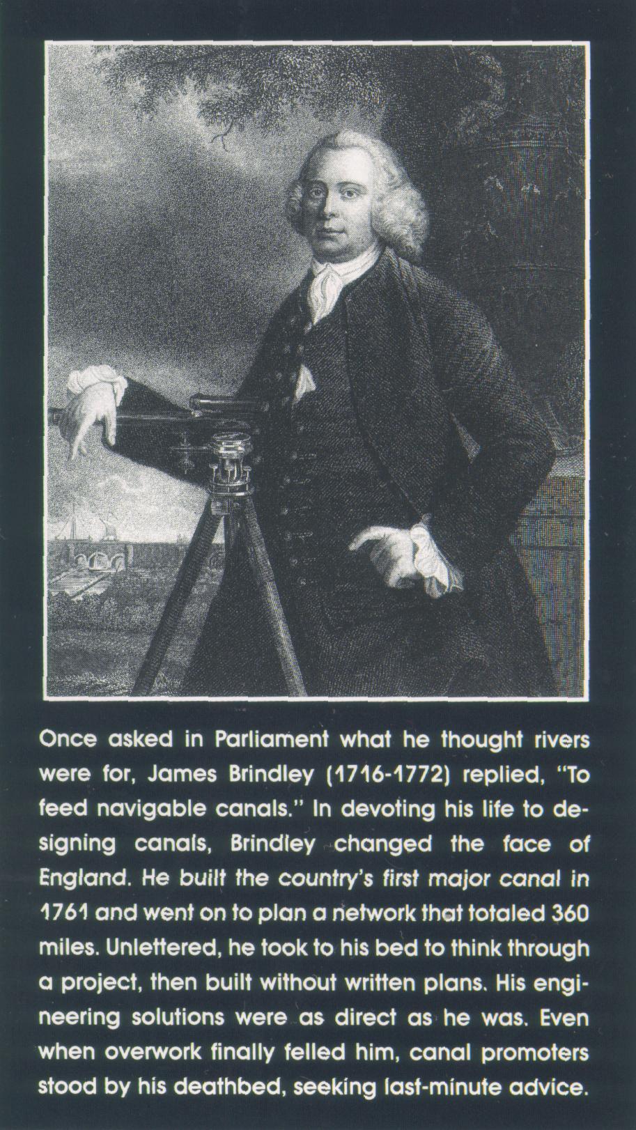
5 5.1 Introduction James Brindley ( ) 141
6 5. Vertical Datums Two. The vertical Datum is not a mathematical surface (i.e. ellipsoid), but referenced to the geoid (equipotential surface of the earth s gravity field closely approximating sea level). Canadian Geodetic vertical datum (CGVD8) [USA (NGVD9)] Since 198, over km of lines have been added to the system Defined in 198, based on only 30,000 km of levelling. There are over 75,000 benchmarks The adjustment of the datum, depended on the tidal stations at Halifax, Yarmouth, and Father Point, on the Atlantic, at Vancouver and Prince Rupert on the Pacific, and on Rouses Point [Quebec]. US National Geodetic Vertical Datum NGVD9 106,75km of levelling constituting 46 closed loops 6 Tidal Stations across North America were used to provide a fixed datum Alaska has own vertical datum 14

7 5. Vertical Datums Map of primary Canadian Vertical Control Network. Consisting of more than 130,000 km of precise leveling to over 75,000 bench marks. Elevations refer to CGVD8 143
8 5. Vertical Datums IGLD 1985 (Canada & U.S.A) Great Lakes Vertical Datum - Completed in 199 This datum was established in 1955 to give more accurate hydrological readings. IGLD was the first common datum for the U.S. and Canada Revised in 1985 and a new reference zero point at Rimouski, Quebec was established. North American Vertical Datum NAVD 88 (Canada & U.S.A) Involved a redefinition and readjustment of the geodetic vertical control networks. In June, 1991 a continental adjustment was carried out This included 77,000 km of levelling in Canada NAVD was referenced to the 1985 IGLD datum 144

9 5. Vertical Datums IMPACT OF VERTICAL ADJUSTMENT NAVD88 minus NAVD9 Approximate shift in vertical datum (in mm) for U.S.A. NOTE: Father s Point, Quebec, only tidal station used today in N.A. for mean sea level determination 145
10 5.3 Levelling Techniques and Corrections Precise elevations are determined relative to the datum by a process known as. Point established are called bench marks (BM) or temporary bench marks Rods are held vertically, A on a point of known elevation and B on a turning point The change in elevation is calculated by subtracting the sum (B.S.) - Sum (F.S.) = D Elevation Accuracy is related to the difference between forward and backward leveling. 146
11 5.3 Levelling Techniques and Corrections Production Varies according to terrain 100 to 00 set-ups per day 3. 8 to 14 km/day Routes Railways, Roads, Rivers, Ice, etc. Special points Balance B.S. s and F.S. s. Line of Sight 0.5 m above grd. Max. length of shots m A B.S. F.S. B D Elev. g D Elev. = D Elev. = + (higher elevation) 147
12 5.3 Levelling Techniques and Corrections Correction for Curvature and Refraction (Cc+r) (Approx.) R R + D + D = ( R = R + C C + C C ) + 0 RC C D RC = C ft. ft. 580 x 580 D mi. mi. C ( ft.) = = C D, for D in miles x 0,890,000 ft. 1 C - R C C 7 C + (ft.) = D, or C + (m) = C R C R 148
13 5.3 Levelling Techniques and Corrections mm Axis of the vial tangent at midpoint R SENSITIVITY ANGLE S = q FOR ARC = mm a a Level rod d Level Line g 149
14 5.3 Levelling Techniques and Corrections d a = ARCSIN a d q = ARC SIN [ where, n = number of mm divisions] a n d p rads q " = [ Note : arc 1" = = ] a ( n) arc 1" 360x60x60 150

15 5.3 Levelling Techniques and Corrections Example For parallel plate micrometer, d = 5 mm when rotated 30 o. Calc. thickness of glass if refractive index =
16 5.3 Levelling Techniques and Corrections t AB = BC = d cosa 1 = sina 1 sin ( 90 + a ) t d = sin ( a1 -a) cosa t d = (sina1 cosa - cosa 1sin a ) cosa d = t (sina 1- cosa - cosa 1sin a ) 1- sin a 1 d = t sina 1 1- n - sin a 1 ( - ) d = t a 1 1 [ in Rads] 15


17 5.3 Levelling Techniques and Corrections Precise Leveling Equipment Parallel plate micrometer 40x magnification /mm sensitivity or better Different Observers Rods Circular levels on rods Foot plates for turning points Sun shade for instrument 153
18 5.3 Levelling Techniques and Corrections Specifications The different orders of vertical control are defined in terms of the allowable discrepancy between independent forward and backward leveling between bench marks as follows: Special First Order First Order ± 4 mm k Second Order ± 8 mm k Third Order ± 4 mm k Fourth Order ± 10 mm k Note: k(kilometers) = One way distance between bench marks along leveling route 154
19 5.3 Levelling Techniques and Corrections U.S. Geodetic Survey Leveling Specifications 155

20 5.4 Bench Marks Design and Construction Defined as fixed reference point whose elevation has been determined and whose position is so described that it may be identified in the future (no vertical movement should take place. Value of level line is a function of the number of properly positioned bench marks. Improperly set bench mark(s) provide totally misleading information Bench marks either permanent or temporary 156
21 Bench Marks Design and Construction V CUT 1 16 DEEP MATERIAL: BRONZE 1 8 DRILL 1 4 DIA. SLOT SURVEY TABLET MARKER TYPE
22 5.4 Bench Marks Design and Construction CONVEX CURVATURE ON TOP BRONZE CAP THREADED TO PIPE PIN TO SECURE CAP TO COLUMN 4 to 8 1 GALVANIZED STEEL PIPE 7 DIA. BASE (CAST IRON) THREADED TO PIPE SURVEY IRON PIPE MARKER WITH BASE TYPE 3 158
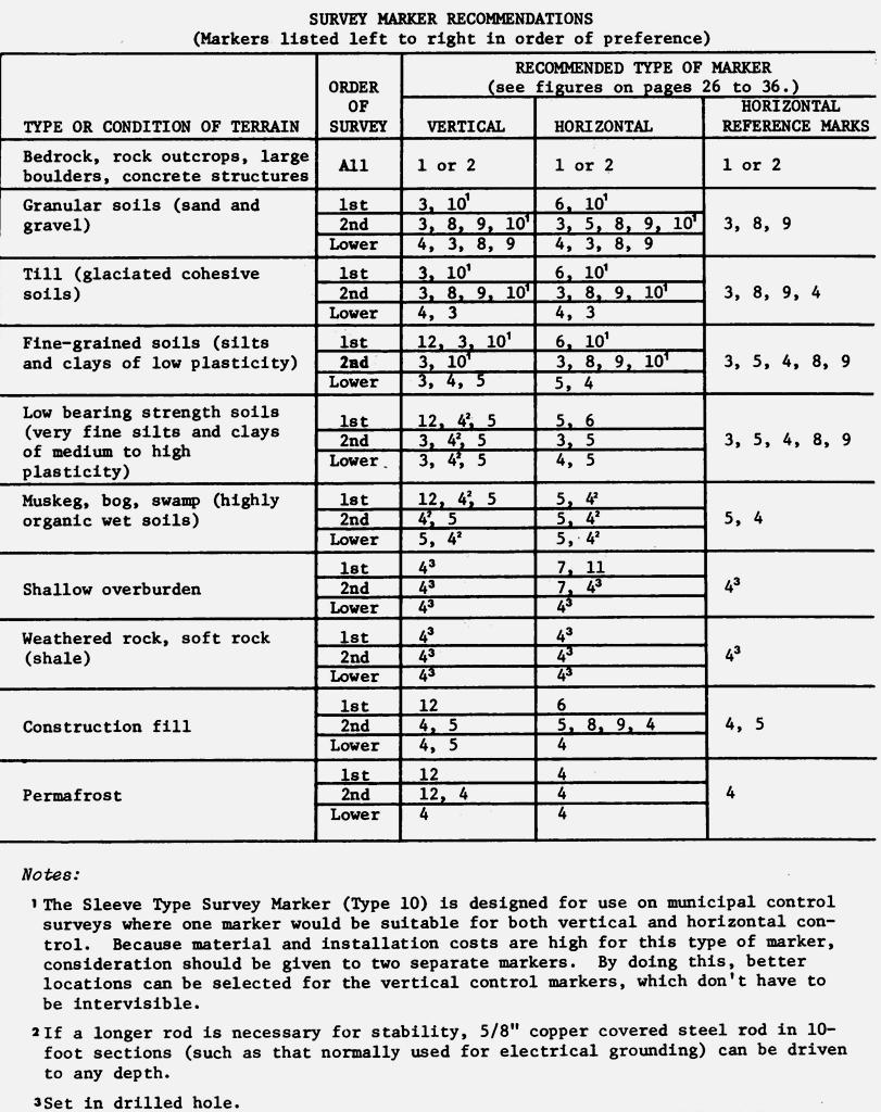
23 5.4 Bench Marks Design and Construction CAST IRON RIM & COVER TYPE 1 OR MARKER UPPER 6 OF PIPE FILLED WITH NON-SHRINKING GROUT GALV. STEEL PIPE DRIVEN TO DESIRED DEPTH EARTH MARKER MAY BE SET WITH BRONZE TABLET FLUSH WITH GROUND LEVEL. PILE DRIVEN SURVEY PIPE MARKER TYPE 5 159
24 5.4 Bench Marks Design and Construction CYLINDRICAL FORM MINIMUM 10 TYPE 1 or MARKER GROUND LEVEL CONCRETE SUBSURFACE ROCK 4-3 REINFORCING STEEL BARS 4 SURVEY MARKER IN SHALLOW OVERBURDEN TYPE 7 160
25 ABOUT 3 ABOUT 3 COMPRE SIBLE SOIL GALVANIZED IRON RIM AND COVER REFUSAL OR BEDROCK CASING LIFTED 1 GALVANIZED STEEL PIPE CASING (COUPLED IN SECTIONS) GALVANIZED STEEL PIPE 3 8 (COUPLED IN SECTIONS) FOOT (see detail) * N.R.C. TYPE DEEP BENCH MARK TYPE 1 * National Research Council 5 STAINLESS STEEL BALL WELDED TO COUPLING ANNUILAR SPACE BETWEEN PIPES FILLED WITH SAE 80 OIL 10 CONCRETE TILE FILLED WITH CRUSHED STONES a = 1 38 a to 1 1 TO FIT 1 PIPE CASING STD. PIPE THREAD 40 TIP CUT OFF MATERIAL - COLD ROLLED STEEL STEEL FOOT DETAIL CASING LIFTED GALVANIZED IRON RIM AND COVER STAINLESS STEEL BALL WELDED TO COUPLING ANNUILAR SPACE BETWEEN PIPES FILLED WITH SAE 80 OIL 10 CONCRETE TILE FILLED WITH CRUSHED STONES COMPRESSIBLE SOIL 1 GALVANIZED STEEL PIPE CASING (COUPLED IN SECTIONS) 3 8 GALVANIZED STEEL PIPE (COUPLED IN SECTIONS) a a = to 1 1 TO FIT 1 PIPE CASING STD. PIPE THREAD STEEL FOOT DETAIL 40 REFUSAL OR BEDROCK FOOT (see detail) N.R.C. TYPE DEEP BENCH MARK * TYPE 1 * National Research Council TIP CUT OFF MATERIAL - COLD ROLLED STEEL 161
26 16
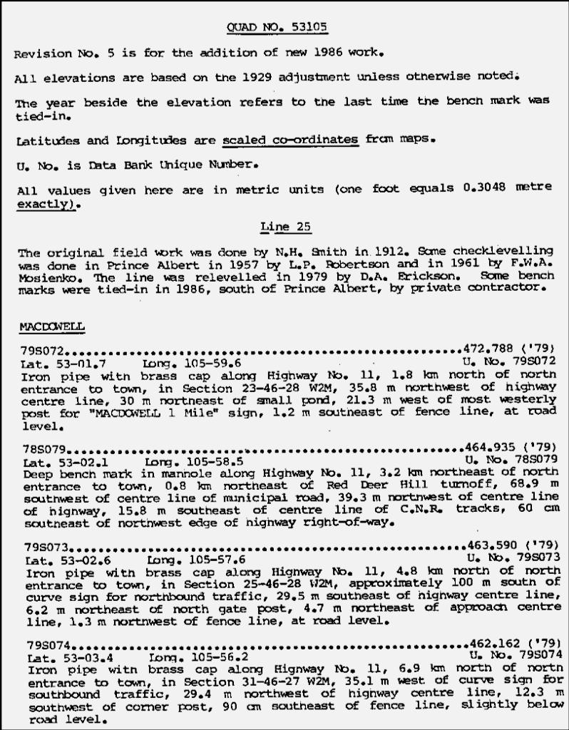
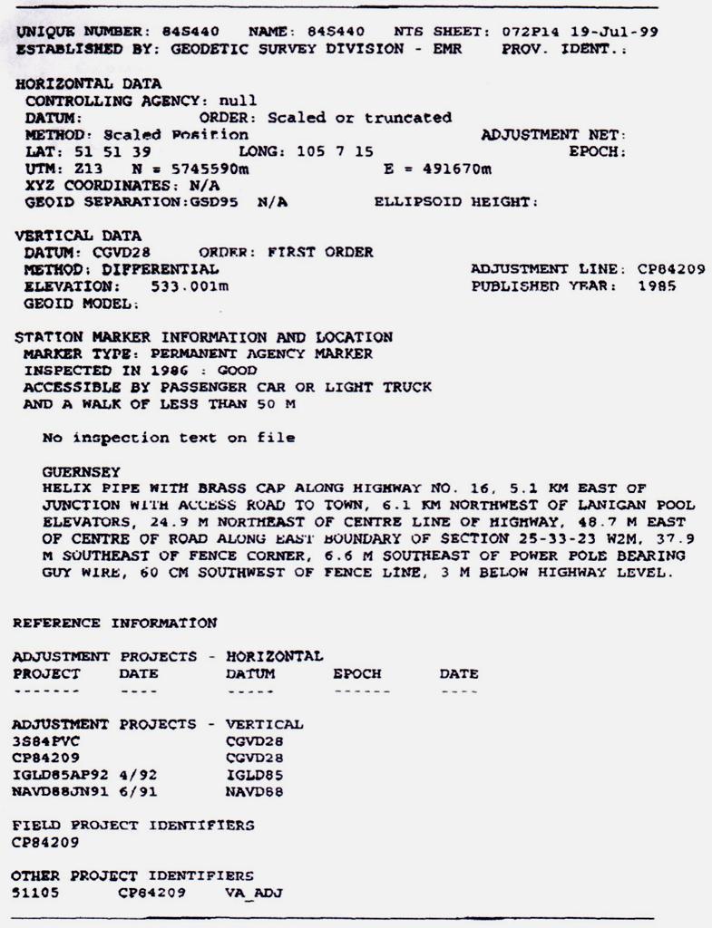
27 163

28 =55 N =53 N

29 3 3 3S Scale 1:500,000 QUAD NO
30 166
31 5.5. WWW OPDS: World Wide Web Online Product Delivery Service WWW OPDS replaced the Canadian Geodetic Bulletin Board Service (CGBBS) early in 1999, to allow Geodetic clients direct access to Geodetic products and services. The following Products are available through CSRS: Primary Vertical and Horizontal Networks Products (survey station data) Direct access to the Canadian Spatial Reference System (CSRS) via the Canadian Active Control System (CACS) Geodetic Software and Related Data Products Publications Coordinates issued by the Division for horizontal networks are based on the North American Datum 1983 (NAD83), which is compatible with the World Geodetic System 1984 (WGS84). 167
32 5.5. WWW OPDS: World Wide Web Online Product Delivery Service Computer listings of horizontal and/or vertical survey stations are available in the following formats: Long: Short: Geographics, UTM's, cartesians, height and undulation, station monumentation, location description and inspection data. Geographics, UTM's, cartesians, height and undulation. Geolist: Geolist-UTM: Geographics, height, marker class and condition. Same as GEOLIST with UTM coordinates. For guest users of the CSRS on-line data only the geolist format is available and the elevations of the stations are rounded off
33 169
34 5.6 Trigonometric Leveling CD = DE tan a DF = (C & R) ED DH = AE + DF + DE tana - BC AB DH = AE + DF + EC sina - BC AB 170

35 5.7 Barometric Levelling 3 methods of survey Single barometer Three barometers (two fixed, one higher & one lower) 171
LEVELING. Definitions
 Definitions An elevation of a point : The vertical distance between the point and the reference level surface ( datum ),the most commonly used datum is the mean sea level (MSL ). Leveling : The process
Overview of New Datums NOAA s National Geodetic Survey
 Overview of New Datums NOAA s National Geodetic Survey February 3, 2015 1 NGS s Mission and Role NGS Mission: To define, maintain, and provide access to the National Spatial Reference System to meet our
determining the relative height of different
 Levelling & Contouring Principle of levelling Principle:-The principle of levelling is to obtain horizontal line of sight with respect to which vertical distances of the points above or below this line
Geodesy, Geographic Datums & Coordinate Systems
 Geodesy, Geographic Datums & Coordinate Systems What is the shape of the earth? Why is it relevant for GIS? 1/23/2018 2-1 From Conceptual to Pragmatic Dividing a sphere into a stack of pancakes (latitude)
Geodetic Positioning Refresher
 Geodetic Positioning Refresher by Joan Yau PhD ABCLS AGM 2016, Kimberley BC Contents Horizontal / Vertical Datums and Epochs used in BC and Canada How do we reference our project coordinates to BC datums
Appendix A Lower Columbia River Chart Datum Modeling
 Appendix A Lower Columbia River Chart Datum Modeling David Evans and Associates, Inc. David Evans and Associates, Inc. 2801 SE Columbia Way, Ste. 130 Vancouver, WA 98661 (360) 314-3200 1.0 Vertical Datum
Foundation Specifications for 5.6-Meter Modular Earth Station Antennas
 Installation Instructions Bulletin 237029 Foundation Specifications for 5.6-Meter Modular Earth Station Antennas Revision A Introduction This document specifies typical foundation characteristics, designs,
Foundation Specifications for 7.6-Meter Modular Earth Station Antennas
 Installation Instructions Foundation Specifications for 7.6-Meter Modular Earth Station Antennas Bulletin 237186A Revision A Introduction This document specifies typical foundation characteristics, designs,
Leveling. Double-Rodded Leveling. Illustrative Problem. Double-Rodded Leveling 8/17/2014
 Double-Rodded Leveling Double-Rodded Leveling A method of determining the differences in elevation between points by employing two level routes simultaneously Two turning points are established such that
An NGS Illustrated Guide to Geodesy for GIS Professionals
 An NGS Illustrated Guide to Geodesy for GIS Professionals Michael Dennis, RLS, PE michael.dennis@noaa.gov Esri User Conference San Diego Convention Center July 14-18, 2014 San Diego, CA Why should we care
Lecture # 7 Coordinate systems and georeferencing
 Lecture # 7 Coordinate systems and georeferencing Coordinate Systems Coordinate reference on a plane Coordinate reference on a sphere Coordinate reference on a plane Coordinates are a convenient way of
8/17/2014. Process of directly or indirectly measuring vertical distances to determine the elevation of points or their differences in elevation
 Process of directly or indirectly measuring vertical distances to determine the elevation of points or their differences in elevation Leveling results are used: To design highways, railroads, canals, sewers,
Map Basics: Datums and Coordinate Systems
 Map Basics: Datums and Coordinate Systems ESRM 304 Autumn 2015 Contributors: Phil Hurvitz, Peter Schiess, Eric Turnblom 1 of 39 Datums, land division systems, & coordinate systems Datums (from Wikipedia)
International Journal of Scientific & Engineering Research, Volume 7, Issue 9, September ISSN
 International Journal of Scientific & Engineering Research, Volume 7, Issue 9, September-2016 769 Leveling By Differential Global Position System (Case Study) Assistant Lecturer Bashar Halleem Muhsen Al-Yasery
Datums for a Dynamic Earth
 Datums for a Dynamic Earth Based on a paper given at the American Society of Agricultural and Biological Engineers (ASABE) Conference in Reno, Nevada June 2009 Rollin StrohmanPh.D. Tom Mastin L.S Background
Overview of New Datums
 Overview of New Datums Scott Lokken NC Advisor NOAA s National Geodetic Survey 9/4/2015 1 New Datums are Coming in 2022! Both a new geometric and a new geopotential (vertical) datum will be released in
The several methods for making linear measurements are quite simple and straightforward. They are described below:
 INTRODUCTION TO LINEAR MEASUREMENTS Many pay items are measured on the basis of linear measurements - items such as guardrail, pipe culvert, curb and gutter, fencing, etc. These measurements usually are
ELEMENTS OF THE NATIONAL SPATIAL REFERENCE SYSTEM
 Dave Doyle NGS Chief Geodetic Surveyor dave.doyle@noaa.gov 301-713-3178 ELEMENTS OF THE NATIONAL SPATIAL REFERENCE SYSTEM ESRI SURVEY SUMMIT San Diego, CA June 17, 2007 ftp://ftp.ngs.noaa.gov/dist/daved/esri
2. Remove from the Standard Plate manual: Standard Plate Index, Sheets 1-4 of 4, Numerical Index of Standard Plates (August 31, 2012)
") MINNESOTA DEPARTMENT OF TRANSPORTATION DEVELOPED BY: Design Standards ISSUED BY: Office of Program Management & Technical Support, Design Support Section TRANSMITTAL LETTER NO. (12-04) MANUAL: Standard
MINNESOTA DEPARTMENT OF TRANSPORTATION DEVELOPED BY: Design Standards ISSUED BY: Office of Program Management & Technical Support, Design Support Section TRANSMITTAL LETTER NO. (12-04) MANUAL: Standard
Suveying Lectures for CE 498
 Suveying Lectures for CE 498 SURVEYING CLASSIFICATIONS Surveying work can be classified as follows: 1- Preliminary Surveying In this surveying the detailed data are collected by determining its locations
Introduction to Datums James R. Clynch February 2006
 Introduction to Datums James R. Clynch February 2006 I. What Are Datums in Geodesy and Mapping? A datum is the traditional answer to the practical problem of making an accurate map. If you do not have
Overview of Tides and Water Levels
 Overview of Tides and Water Levels www.tidesandcurrents.noaa.gov New Orleans, Baton Rouge, Lafayette, LA March 2009 Gerald Hovis, NOAA - National Ocean Service William Sweet, NOAA - National Ocean Service
3. GENERAL TIDAL DATUM COMPUTATION PROCEDURES
 3. GENERAL TIDAL DATUM COMPUTATION PROCEDURES 3.1 Datum Computation Procedures Overview A vertical datum is termed a tidal datum when it is defined by a certain phase of the tide. Tidal datums are local
Typical Drawings for Schools
 0.85 1.7 0.85 3 3 0.6 3 3 0.85 1.7 0.85 0.3 4 4 1 1 2 2 0.425 0.425 0.425 0.425 1.2 2.4 1.2 0.6 0.6 4 4 1 1 3 3 0.4 0.6 0.3 0.3 3 3 4 4 0.4 4 4 1 1 2 2 Detail of (W 1.2 x 0.4 m) Detail of (W0.6 x 0.4 m)
U.S. Army Corps of Engineers: Review of Progress Toward Consistent Vertical Datums. by Jim Garster and Mark Huber
 U.S. Army Corps of Engineers: Review of Progress Toward Consistent Vertical Datums by Jim Garster and Mark Huber i ii Abstract A vertical datum is the most important part of any geospatial data, no matter
CHAPTER 2 GEODESY AND DATUMS IN NAVIGATION
 CHAPTER 2 GEODESY AND DATUMS IN NAVIGATION GEODESY, THE BASIS OF CARTOGRAPHY 200. Definition Geodesy is the application of mathematics to model the size and shape of the physical earth, enabling us to
33/3527A. Devices covered by these instructions: 33/3527A-F (Fire) Surface Vertical Rod Exit Device
 Surface Vertical Rod Exit Device") *911403-00* 911403-00 Surface Vertical Rod Exit Device 33/3527A Installation Instructions Devices covered by these instructions: 33/3527A Surface Vertical Rod Exit Device 33/3527A-F (Fire) Surface Vertical
*911403-00* 911403-00 Surface Vertical Rod Exit Device 33/3527A Installation Instructions Devices covered by these instructions: 33/3527A Surface Vertical Rod Exit Device 33/3527A-F (Fire) Surface Vertical
TYPICAL SECTIONS TYPICAL NO. 1 (MAINLINE) STA TO STA STA TO STA ROUNDING DETAIL TYPICAL NO.
 STA TO STA STA TO STA ROUNDING DETAIL TYPICAL NO.") FILL SECTION TYPICAL NO. 1 (MAINLINE) STA. 2434. TO STA. 244035.16 STA. 244396.83 TO STA. 2449. CUT SECTION ROUNDING DETAIL FILL SECTION TYPICAL NO. 3 (DETOUR) CUT SECTION STA. 242849.86 TO STA. 2453.88
FILL SECTION TYPICAL NO. 1 (MAINLINE) STA. 2434. TO STA. 244035.16 STA. 244396.83 TO STA. 2449. CUT SECTION ROUNDING DETAIL FILL SECTION TYPICAL NO. 3 (DETOUR) CUT SECTION STA. 242849.86 TO STA. 2453.88
FACULTY OF CIVIL ENGINEERING & EARTH RESOURCES ENGINEERING SURVEY FIELDWORK. LEVELING (Standard Of Procedure)
") FACULTY OF CIVIL ENGINEERING & EARTH RESOURCES ENGINEERING SURVEY FIELDWORK LEVELING (Standard Of Procedure) Subject Code Date Group Number Student Name & ID Number Group Member Name & ID Number 1 2 Lecturer
FACULTY OF CIVIL ENGINEERING & EARTH RESOURCES ENGINEERING SURVEY FIELDWORK LEVELING (Standard Of Procedure) Subject Code Date Group Number Student Name & ID Number Group Member Name & ID Number 1 2 Lecturer
Midwest Roadside Safety Facility
 B 64" 1626 602'-8 1/16" 183695 548'-0" 167030 1 2 3 4 5 6 7 8 9 10 11 12 14 15 16 17 18 20 21 22 23 24 25 26 27 28 29 30 31 32 33 34 35 36 373839 40 25 IMPACT 1500A 48" 12 27'-5" 8355 [] 3x7 CL A Galvanized
LocoGear. Technical Bulletin - 14 November 28, 2003 Copyright 2003 by LocoGear LIVE STEAM CASTINGS. Tech Bulletin - 14
 LIVE STEAM CASTINGS LocoGear Tech Bulletin - 14 John D.L. Johnson 3879 Woods Walk Blvd Lake Worth, FL 33467-2359 jjohnson@locogear.com www.locogear.com Technical Bulletin - 14 November 28, 2003 Copyright
Instruction with Hands-on Practice: Creating a Bathymetric Database & Datum Conversion
 Instruction with Hands-on Practice: Creating a Bathymetric Database & Datum Conversion Tanya Beck Coastal and Hydraulics Laboratory Engineer Research and Development Center May 17, 2010 US Army Corps of
Determining Accurate Elevations: Datums & Tools, Today & Tomorrow
 Determining Accurate Elevations: Datums & Tools, Today & Tomorrow Association of State Floodplain Managers Annual Meeting Grand Rapids, MI Christine Gallagher June 21, 2016 Overview NGS Mission Important
GNSS 101 Bringing It Down To Earth
 GNSS 101 Bringing It Down To Earth Steve Richter Frontier Precision, Inc. UTM County Coordinates NGVD 29 State Plane Datums Scale Factors Projections Session Agenda GNSS History & Basic Theory Coordinate
Using GPS to Establish the NAVD88 Elevation on Reilly The A-order HARN Station at NMSU
 Using GPS to Establish the NAVD88 Elevation on Reilly The A-order HARN Station at NMSU Earl F. Burkholder, PS, PE New Mexico State University Las Cruces, NM 88003 July 005 Introduction GPS has become an
NATIONAL VDATUM -- THE IMPLEMENTATION OF A NATIONAL VERTICAL DATUM TRANSFORMATION DATABASE
 NATIONAL VDATUM -- THE IMPLEMENTATION OF A NATIONAL VERTICAL DATUM TRANSFORMATION DATABASE Bruce Parker, Dennis Milbert, Kurt Hess, and Stephen Gill National Ocean Service, NOAA The National Ocean Service
Definition and use of the New Zealand Vertical Datum Matt Amos Senior Advisor Geodesy
 Definition and use of the New Zealand Vertical Datum 2009 Matt Amos Senior Advisor Geodesy NZIS Continuing Professional Development Programme, November 2009 Overview Height Theory Heights in New Zealand
GNSS & Coordinate Systems
 GNSS & Coordinate Systems Matthew McAdam, Marcelo Santos University of New Brunswick, Department of Geodesy and Geomatics Engineering, Fredericton, NB May 29, 2012 Santos, 2004 msantos@unb.ca 1 GNSS GNSS
Basic Geodetics. Bobby Saleh Guidon Energy April 13, 2017
 Experts in Geomatics, Surveying, Positioning, Geospatial Data, and Mapping Sciences Basic Geodetics Bobby Saleh Guidon Energy b.saleh@guidonenergy.com April 13, 2017 The Earth is NOT flat Q: So what does
FieldGenius Technical Notes GPS Terminology
 FieldGenius Technical Notes GPS Terminology Almanac A set of Keplerian orbital parameters which allow the satellite positions to be predicted into the future. Ambiguity An integer value of the number of
Gable HomeshedsTM INSTALLATION BEFORE YOU START TOOLS REQUIRED GUIDE LARGE SPAN. Council Approval. Before Starting
 INSTALLATION GUIDE Gable HomeshedsTM LARGE SPAN BEFORE YOU START Council Approval It is important to contact your local council before building your Stratco Gable Homeshed. You will have already received
Manhole or Catch Basin Type A & B Cone Sections Precast - Design F Manhole or Catch Basin Cover (Reducer Cone Section Precast) Design D
 Design D") MINNESOTA DEPARTMENT OF TRANSPORTATION DEVELOPED BY: Design Standards ISSUED BY: Office of Program Management and Technical Support, Design Support Section TRANSMITTAL LETTER NO. (14-02) MANUAL: Standard
MINNESOTA DEPARTMENT OF TRANSPORTATION DEVELOPED BY: Design Standards ISSUED BY: Office of Program Management and Technical Support, Design Support Section TRANSMITTAL LETTER NO. (14-02) MANUAL: Standard
Rodney Hunt. A GA Industries Company Glydaseal Gates
 Rodney Hunt A GA Industries Company Glydaseal Gates GUIDE BRONZE GUIDE BAR FRAME NUT POCKET SEAT FACING RESILIENT INVERT SEAT DISC GUIDE BAR ADJUSTMENT BOLT WITH LOCK NUT GUIDE BAR ATTACHING BOLT The Glydaseal
Guidelines for Laying Targets for Ground Control Points
 Guidelines for Laying Targets for Ground Control Points Overview of target requirements: Three to four unambiguous ground survey targets, recognizable in the satellite photo, are requested. The survey
Standard Plate 7036 is discontinued. It is replaced by Standard Plan Pedestrian Curb Ramp Details.
 DEVELOPED BY: Design Standards ISSUED BY: Office of Program Management & Technical Support, Design Support Section TRANSMITTAL LETTER NO. (12-02) MANUAL: Standard Plates DATED: May 11, 2012 SUBJECT: Standard
INTERAPID Small Bench SHE.30 or SHE.35
 0 to 0 mm Mobile measuring bolt mounted on a plain bearing, also fitted with a semi-circular releasing disc plate. Measuring inserts supplied in pairs. One is tighten on the measuring bolt, the other on
Active and Passive Microwave Remote Sensing
 Active and Passive Microwave Remote Sensing Passive remote sensing system record EMR that was reflected (e.g., blue, green, red, and near IR) or emitted (e.g., thermal IR) from the surface of the Earth.
Pipe Product Catalog Table of Contents
 Pipe Product Catalog Table of Contents Section A: Drawing #: Page Description A1 Reinforced Concrete Pipe A3 Storm Manhole Sizing Chart (48" - 96") A3.1 Storm Manhole Sizing Chart (108" - 144") A4 48"
SURVEYING 1 CE 215 CHAPTER -3-
 Civil Engineering Department SURVEYING 1 CE 215 CHAPTER -3- PROFILE AND CROSS SECTION LEVELING 1 2 1 3 4 2 5 6 3 7 8 4 9 10 5 11 12 6 13 14 7 15 16 8 17 18 9 19 20 10 21 22 11 23 24 12 25 26 13 27 28 14
Coordinates, Datums, and Map Projection
 Coordinates, Datums, and Map Projection Two views on the World Intersect at 90 o angles Latitude/ Longitude is a Spherical System Acceptable latitudes/longitudes i) W125 o 27 33 ii) N92 o 45 12 iii)
TO O L K IT. Public Bike Repair
 TO O L K IT Public Bike Repair The Dero Tool Kit includes all the necessary tools to perform most routine maintenance and adjustments on most bikes. All the tools are securely fastened with stainless steel
CertainTeed INSTALLATION GUIDE SIMTEK FENCE PRODUCTS. Fence Installation Guide 3', 4' & 6' High
 CertainTeed INSTALLATION GUIDE SIMTEK FENCE PRODUCTS Fence Installation Guide 3', 4' & 6' High INSTALLATION GUIDE These instructions are designed to assist both professional installers and do-it-yourselfers
PART XIII: HYDRAULIC/ HYDROLOGY SURVEYS
 PART XIII: HYDRAULIC/ HYDROLOGY SURVEYS 13.1 Purpose and Scope Hydraulic surveys are required for flow analysis to determine bridge and culvert design characteristics. A hydraulic survey is usually but
98/9927. Devices covered by these instructions: Surface Vertical Rod Exit Device
 911375-00 Surface Vertical Rod Exit Device 98/9927 Installation Instructions Devices covered by these instructions: 98/9927 Surface Vertical Rod Exit Device 98/9927-F (Fire) Surface Vertical Rod Exit Device
STATE UNIVERSITY CONSTRUCTION FUND
 DIRECTIVE 1C-12 Issue date: August 2012 1. General SURVEY, MAPPING AND UTILITY LOCATING This Directive has been developed as a general guide for the survey and mapping effort required for Fund projects.
MANHOLES PART I: GENERAL. A. Precast Concrete Manholes
 MANHOLES PART I: GENERAL A. Precast Concrete Manholes 1) Manholes shall be made of precast concrete sections of which the top section shall be eccentric or flat slab top. The bottom section shall be a
Survey Requirements. Design Guidelines and Standards. June Office of the University Architect
 Design Guidelines and Standards Survey Requirements June 2004 Office of the University Architect Construction Management P.O. Box 210181 Cincinnati, Ohio 45221-0181 Table of Contents Survey Requirements
Course Instructions. 3 Easy Steps to Complete the Course: 1.) Read the Course PDF Below.
 Read the Course PDF Below.") Course Instructions NOTE: The following pages contain a preview of the final exam. This final exam is identical to the final exam that you will take online after you purchase the course. After you purchase
Course Instructions NOTE: The following pages contain a preview of the final exam. This final exam is identical to the final exam that you will take online after you purchase the course. After you purchase
SURVEYOR S REPORT VERTICAL CONTROL FOR CONSTRUCTION C-44 PROJECT
 Post Office Box 1469 Palm City, FL 34991 Martin: 772.286.8083 Fax: 772.283.6174 Statewide: 800.386.1066 www.gcyinc.com SURVEYOR S REPORT VERTICAL CONTROL FOR CONSTRUCTION C-44 PROJECT The purpose of this
24" B B Joint X501 Joint See MARKINGS Note PCB-RXX-350-TL3 " X501 Y301 (Typ.) " A PLAN (reinforced casting option shown) A " dia. Hinge Bar (Typ.) NOT
 A PLAN (reinforced casting option shown) A dia. Hinge Bar (Typ.) NOT") B B Joint Joint See MARKINGS Note PCB-RXX-350-TL3 " Y301 (Typ.) " A PLAN (reinforced casting option shown) A " dia. Hinge Bar (Typ.) NOTES GENERAL: This barrier may be manufactured with reinforcing steel
B B Joint Joint See MARKINGS Note PCB-RXX-350-TL3 " Y301 (Typ.) " A PLAN (reinforced casting option shown) A " dia. Hinge Bar (Typ.) NOTES GENERAL: This barrier may be manufactured with reinforcing steel
1.1 SUMMARY. A. This Section includes the following: 1. Loose steel lintels. 2. Shelf angles. 3. Metal floor plate. 4. Pipe bollards.
 PART 1 - GENERAL 1.1 SUMMARY A. This Section includes the following: 1. Loose steel lintels. 2. Shelf angles. 3. Metal floor plate. 4. Pipe bollards. B. See Division 5 Section "Pipe and Tube Railings"
Determining Accurate Elevations: Datums & Tools, Today & Tomorrow
 Determining Accurate Elevations: Datums & Tools, Today & Tomorrow Maryland Association Floodplain and Stormwater Managers Linthicum Heights, MD Christine Gallagher Oct. 20, 2016 Overview NGS Mission Important
J... K' -ITJ::l/..,HE J) / ~ L ~ I ( ... )i' s.o THEASTERN. -. 'u J. If... 1f. wiseo - P. LAN 'N,LN G. eommiss 0'1\1
 / ~ L ~ I ( ... )i' s.o THEASTERN. -. 'u J. If... 1f. wiseo - P. LAN 'N,LN G. eommiss 0'1\1") J... II K' -ITJ::l/..,HE J) / ~ L ~ I ( t I~,/... -. 'u J )i' s.o THEASTERN ~ wiseo - If... 1f P. LAN 'N,LN G eommiss 0'1\1 SOUTHEASTERN WISCONSIN REGIONAL PLANNING COMMISSION KENOSHA COUNTY Leon T. Dreger
J... II K' -ITJ::l/..,HE J) / ~ L ~ I ( t I~,/... -. 'u J )i' s.o THEASTERN ~ wiseo - If... 1f P. LAN 'N,LN G eommiss 0'1\1 SOUTHEASTERN WISCONSIN REGIONAL PLANNING COMMISSION KENOSHA COUNTY Leon T. Dreger
Current Standard Plates including Transmittal Letters are available on the web at:
 MINNESOTA DEPARTMENT OF TRANSPORTATION DEVELOPED BY: Design Standards ISSUED BY: Office of Project Management and Technical Support, Design Support Section TRANSMITTAL LETTER NO. (17-04) MANUAL: Standard
Mueller Gas Products. Mueller H17800 Curb Stop Tee No Blo Curb Stop Tee Weld x Weld 1440 PSI
 Mueller Gas Products Distributed by: Mountain States Pipe and Supply Colorado Springs, Colorado 80903 1 800 777 7173 Mueller H17800 Curb Stop Tee No Blo Curb Stop Tee Weld x Weld 1440 PSI MUELLER NO-BLO
SURVEYING I CENG 383
 SURVEYING I CENG 383 9/21/2011 2 Introduction Definition An art of collecting data for mapping the relative positions of points above, below or on the surface of the earth. Surveying also includes the
Helical Pier Frequently Asked Questions
 Helical Pier Basics Q: What is a Helical Pier? A: A helical pier or pile is an extendable deep foundation system with helical bearing plates welded to a central steel shaft. Load is transferred from the
Datums and Tools to Connect Geospatial Data Accurately
 Datums and Tools to Connect Geospatial Data Accurately Pamela Fromhertz Colorado State Geodetic Advisor National Geodetic Survey National Oceanic and Atmospheric Administration GIS-T April 18, 2012 Loveland,
VERTICAL DATUM TRANSFORMATIONS FOR KINEMATIC GPS HYDROGRAPHIC SURVEYS. Kurt W. Hess, Dennis G. Milbert, Stephen K. Gill, and Daniel R.
 VERTICAL DATUM TRANSFORMATIONS FOR KINEMATIC GPS HYDROGRAPHIC SURVEYS Kurt W. Hess, Dennis G. Milbert, Stephen K. Gill, and Daniel R. Roman National Ocean Service, NOAA ABSTRACT Kinematic Global Positioning
Installation Instructions
 Column & Beam Units with Debris Netting Installation Instructions Laminated Wood Systems, Inc. Seward, Nebraska 800-949-3526 2015 LWS, INC. AVR-NET INSTALL 05-12-16 AVR Installation Notes 1 Safety The
Utility Structures. Utility vaults, trenches, transformer pads Electrical Pole Bases and switching cubicles
 Utility Structures Utility vaults, trenches, transformer pads Electrical Pole Bases and switching cubicles PRODUCT GUIDE & TECHNICAL REFERENCE MANUAL Providing the right solutions. UTILITY STRUCTURES Perfect
33/3547A. Special tools needed: #10-24 tap Drill bits: #25, 5/16, 13/32, 1/2
 911404-00 Concealed Vertical Rod Exit Device 33/3547A Installation Instructions Devices covered by these instructions: 33/3547A and 33/3548A Concealed Vertical Rod Exit Device 33/3547A-F and 33/3548A-F
YES 40 FS/FI Storefront System Installation Manual
 Installation Manual 2014 YKK AP America Inc. is a subsidiary of YKK Corporation of America. TABLE OF CONTENTS Installation Notes... Page ii PARTS DESCRIPTION YES 40 FS Framing Members... Page 1 YES 40
INSTRUCTIONS: 1. Record the transmittal letter number, date, and subject on the transmittal record sheet located in the front of the manual.
 MINNESOTA DEPARTMENT OF TRANSPORTATION DEVELOPED BY: Design Standards ISSUED BY: Office of Technical Support Design Services Section TRANSMITTAL LETTER NO. (0-03) MANUAL: Standard Plates DATED: September
CHAPTER 3. BASIC GEODESY
 CHAPTER 3. BASIC GEODESY SECTION I. THE GEODETIC SYSTEM A geodetic system serves as a framework for determining coordinates on the Earth s surface with respect to a reference ellipsoid and the geoid. It
.98M Ku-BAND Rx/Tx ANTENNA SYSTEM
 Revision C January 2, 2002 ASSEMBLY MANUAL ANTENNA SYSTEM PRODELIN CORPORATION 1500 Prodelin Drive Newton NC 28658 ANTENNA SYSTEM C Revised Series text B Revised Address 1/2/02 RAH A Revise and Update
HOME STRENGTHENING GUIDE HOW TO ECONOMICALLY STRENGTHEN YOUR HOUSE AGAINST EARTHQUAKES AND HURRICANES
 HOME STRENGTHENING GUIDE HOW TO ECONOMICALLY STRENGTHEN YOUR HOUSE AGAINST EARTHQUAKES AND HURRICANES Grenville W Phillips II BSc, BEng, MASc, MURP, CEng, FIStructE, FCIHT, MAPM, MCSCE, MBAPE Chartered
GEODESY LESSON PLAN Meet Geodesy
 Meet Lesson Plan GEODESY LESSON PLAN Meet Focus Introduction to geodesy Grade Level 9-12 Focus Question What is geodesy, and why is it important? Learning Objectives Students will be able to define geodesy.
5/16" Flange nut. Bolt Keeper Plate (8" Sq. SYS.) (3) 1/2" x 3" Hex head connector zinc plated bolt w/ washers and nut. Anchor 3" sq. 7 Ga.
 (3) 1/2 x 3 Hex head connector zinc plated bolt w/ washers and nut. Anchor 3 sq. 7 Ga.") 2 1/2" x 2 1/2" x 10 Ga. 6" 5" 4" Variable Slipbase (8" Sq. SYS.) 5/16 Corner Bolt W/ nut 5/16" Flange nut Stub Insert (8" Sq. SYS.) Bolt Keeper Plate (8" Sq. SYS.) (3) 1/2" x 3" Hex head connector zinc
2 1/2" x 2 1/2" x 10 Ga. 6" 5" 4" Variable Slipbase (8" Sq. SYS.) 5/16 Corner Bolt W/ nut 5/16" Flange nut Stub Insert (8" Sq. SYS.) Bolt Keeper Plate (8" Sq. SYS.) (3) 1/2" x 3" Hex head connector zinc
SUBJECT: Standard Plates 4132, 4155, Drainage Structures and Castings Info
 MINNESOTA DEPARTMENT OF TRANSPORTATION DEVELOPED BY: Design Standards ISSUED BY: Office of Project Management and Technical Support, Design Support Section TRANSMITTAL LETTER NO. (18-01) MANUAL: Standard
What makes the positioning infrastructure work. Simon Kwok Chairman, Land Surveying Division Hong Kong Institute of Surveyors
 What makes the positioning infrastructure work The experience of the Hong Kong Satellite Positioning Reference Station Network Simon Kwok Chairman, Land Surveying Division Hong Kong Institute of Surveyors
Modeling, Analyzing and Fabrication of Lifting SPRhook for Borewell Pipe
 2014 IJEDR Volume 2, Issue 1 ISSN: 2321-9939 Modeling, Analyzing and Fabrication of Lifting SPRhook for Borewell Pipe 1 S.Prithiviraj, 2 S.Ravikumar 1 Post Graduate Student, 2 Assistant Professor Department
SUBJECT: Standard Plate 9102 Turf Establishment Areas At Pipe Culvert Ends
 MINNESOTA DEPARTMENT OF TRANSPORTATION DEVELOPED BY: Design Standards ISSUED BY: Office of Project Management and Technical Support, Design Support Section TRANSMITTAL LETTER NO. (17-03) MANUAL: Standard
SECTION STEEL LIGHTING STANDARDS. 1. Electrical conduit and fittings; Section
 02760-1 of 5 SECTION 02760 STEEL LIGHTING STANDARDS 02760.01 GENERAL A. Description Steel lighting standards shall include, but not necessarily be limited to, furnishing and installing steel lighting poles,
INTEGRATING BATHYMETRY, TOPOGRAPHY, AND SHORELINE, AND THE IMPORTANCE OF VERTICAL DATUMS
 INTEGRATING BATHYMETRY, TOPOGRAPHY, AND SHORELINE, AND THE IMPORTANCE OF VERTICAL DATUMS Bruce Parker, Dennis Milbert, Kurt Hess, and Stephen Gill National Ocean Service, NOAA 1315 East-West Highway Silver
Department of Civil and Environmental Engineering
 Department of Civil and Environmental Engineering CEE213L Surveying & Introduction to GIS Lab SURVEYING LABORATORY NORTH SOUTH UNIVERSITY Center of Excellence in Higher Education The First Private University
Utilizing A GNSS Network Solution for Utility Applications
 Utilizing A GNSS Network Solution for Utility Applications David Newcomer, PE, PLS GPServ, Inc. newcomer@ (407) 601-5816 AGENDA Types and accuracies of data collection o Autonomous o Meter + o Sub-meter
1. Enumerate the most commonly used engineering materials and state some important properties and their engineering applications.
 Code No: R05310305 Set No. 1 III B.Tech I Semester Regular Examinations, November 2008 DESIGN OF MACHINE MEMBERS-I ( Common to Mechanical Engineering and Production Engineering) Time: 3 hours Max Marks:
Midwest Roadside Safety Facility
 19'-11 1/2" 6083 239'-11 1/2" 73139 Impact 1100C 25 43 5/16" 1100 upstream from the upstream face of the first shear fender downstream of the joint between barrier nos. 7 and 8 Upstream End Downstream
Trade of Toolmaking. Module 3: Milling Unit 9: Precision Vee Block Assembly Phase 2. Published by. Trade of Toolmaking Phase 2 Module 3 Unit 9
 Trade of Toolmaking Module 3: Milling Unit 9: Precision Vee Block Assembly Phase 2 Published by SOLAS 2014 Unit 9 1 Table of Contents Document Release History... 3 Unit Objective... 4 Introduction... 4
Installation Guide. Capped Cellular PVC Fencing. Table of Contents. Storage and Handling Tools Needed Fence Layout and Locating Posts
 Capped Cellular PVC Fencing Installation Guide Table of Contents Storage and Handling Tools Needed Fence Layout and Locating Posts Installation instructions 4 x 4 Over Sleeve Post - 3.5 Rail Privacy Shadowbox
Distribution Restriction Statement Approved for public release; distribution is unlimited.
 CECW-EP Engineer Manual 1110-1-1005 Department of the Army U.S. Army Corps of Engineers Washington, DC 20314-1000 Engineering and Design TOPOGRAPHIC SURVEYING Distribution Restriction Statement Approved
Traffic and Roadway Improvements - Rte 123 (Belmont Street) Brockton, MA Client: BETA Group, Inc.
 Brockton, MA Client: BETA Group, Inc.") HIGHWAY PROJECT EXPERIENCE Traffic and Roadway Improvements - Rte 123 (Belmont Street) Brockton, MA Client: BETA Group, Inc. Alpha provided survey services to prepare a base plan of an approximately 2900
HIGHWAY PROJECT EXPERIENCE Traffic and Roadway Improvements - Rte 123 (Belmont Street) Brockton, MA Client: BETA Group, Inc. Alpha provided survey services to prepare a base plan of an approximately 2900
Current Standard Plates including Transmittal Letters are available on the web at:
 MINNESOTA DEPARTMENT OF TRANSPORTATION DEVELOPED BY: Design Standards ISSUED BY: Office of Project Management and Technical Support, Design Support Section TRANSMITTAL LETTER NO. (15-03) MANUAL: Standard
Section Member. H (in.) WT. lb./ft. Pull Out Strength Slip Resistance Torque Size / Thread All Series
 WT. lb./ft. Pull Out Strength Slip Resistance Torque Size / Thread All Series") Design Data Channel TABLE 1 Elements of Sections Properties for Design Single Channels Nominal Thickness (inches) ga = 0.105 ga = 0.075 16 ga = 0.060 Double Channels LEGEND I Moment of inertia S Section
Design Data Channel TABLE 1 Elements of Sections Properties for Design Single Channels Nominal Thickness (inches) ga = 0.105 ga = 0.075 16 ga = 0.060 Double Channels LEGEND I Moment of inertia S Section
BILL HENNING, Prof LS. ACRONYMS
 BILL HENNING, Prof LS. ACRONYMS US 1 WIKIPEDIA: Also known as geodetics, geodetic engineering or geodetics engineering a branch of applied mathematics [2] and earth sciences, is the scientific discipline
Standard for the Australian Survey Control Network
 Standard for the Australian Survey Control Network Special Publication 1 Intergovernmental Committee on Survey and Mapping (ICSM) Geodesy Technical Sub-Committee (GTSC) 30 March 2012 Table of contents
Application of GPS heights to Bay of Fundy multibeam data
 GEOLOGICAL SURVEY OF CANADA OPEN FILE 6658 Application of GPS heights to Bay of Fundy multibeam data David W. Dodd 2010 GEOLOGICAL SURVEY OF CANADA OPEN FILE 6658 Application of GPS heights to Bay of Fundy
F-4 FURNITURE. Contents
 Contents F-4-1 Public Art Pole F-4-2 Banner Pole F-4-3 Typical Banner Installation F-4-4a Banner/Flower Basket Pole F-4-4b Banner/Flower Basket Pole F-4-5 Flower Basket Brackets F-4-6 TTC Station Sign
Applications and Setups
 1 Applications and Setups Manhole stake This section describes three fundamentals for using the Model DG813/613 to install gravity flow pipe; they are Grade, Elevation, and Line otherwise known as G-E-L.