Building a Greek pool. This lesson will continue with the push/pull and off set tools. You will also be using exact measurements and changing the
|
|
|
- Martin Warren
- 5 years ago
- Views:
Transcription

1 Building a Greek pool. This lesson will continue with the push/pull and off set tools. You will also be using exact measurements and changing the sides of a polygon. A new tool will be introduced called the follow me tool.

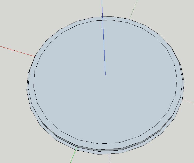
2 Make a circle with 24 sides and a radius of 30 Make an off set of 1

3 Push pull 2 up Off set 2
4 Push pull up 2 Add a 3 rd tier, off set 2 and push pull 2


5 Turn on hidden geometry Use the line tool to trace both side of the stairs, start at the green axis.


6 Other side of stairs Line tool on the top of two stairs


7 Push pull 3 stair up 1 each Erase the bottom circle so the last stair sticks out.

8 Use point at center for the top circle to get a point in the center for our rotation of the stairs. Select just the stairs and orbit to see the top circle. Select the rotate+option and make a copy 45 degrees and 7x. You will now have 8 stairs.


9 Create an off set of 5 Make it a group


10 Make a column on top that is not part of the group. Start with a circle that has 12 sides and push pull it up 12. You also need to add an off set to the bottom and top and push pull them 1. It should look like the following. Select all of the column and make it a group. Move a copy to the other side of the stairs. Stay on the red axis. Set your camera to top and parallel and make sure they look right.

11 Select both columns and rotate them 45 degrees and enter 7x. You should have the following. If you don t have the following stop, undo a few times and try again. Rome wasn t built in a day
12 Select the bases outring (you have it as a group) right click and select edit group. Select the outer ring on the floor and Move+option a copy to the top of the column. Use the red pointer to inference at the top of the colum. Press the UP cursor key once to keep your movement on the blue axis.


13 Push pull this new section 2 Use the line tool and trace the edge of only one of the segments and the circle will close


14 Make sure your still in edit group mode, draw two lines that intersect at the blue axis

15 Make a line from the point of intersection up the blue axis; start drawing the line up the blue axis and enter the exact measurement of 18. Turn off the axis (view/axes) so you can see your line.


16 Draw a rectangle and use the end point to help you get it to snap into place. Zoom in and use the arc tool to draw a profile of the dome.


17 Erase these 3 extra lines Erase the outside of the profile of the dome.

18 We are going to learn a new tool called follow me you need to have the large tool set open: go to the menu and select view/tool pallets/large tool set. 1. Use select and click on the surface of the circle 2. Then click the follow me tool and click the profile of the dome.


19 Clean up any lines by the stairs. Use the eraser. If the eraser makes a hole in your modle then right click the line and select soften.


20 Put the man at the top. Set your camera to parallel projection to help you and switch between top and front (or left or right). Switch your camera back to perspective when done. Rotate to the bottom and draw a line on a segment to fill it in.
21 Finish coloring, have fun. Add the pool in the middle. Remember to use push/pull+option to push the pool down. Use the style window to adjust the sky and ground color.
How to draw the CB South Kerf Bent Clock:
 How to draw the CB South Kerf Bent Clock: Open sketch up, use the Product Design and Woodworking template with Inches as the units. If there is a person in the drawing space, you can delete him/her. When
Sketch-Up Project Gear by Mark Slagle
 Sketch-Up Project Gear by Mark Slagle This lesson was donated by Mark Slagle and is to be used free for education. For this Lesson, we are going to produce a gear in Sketch-Up. The project is pretty easy
SketchUp Training Notes By Professional CAD Systems Ltd Ph
 SketchUp Training Notes By Professional CAD Systems Ltd Ph 07 847 2268 Coffee Table: Using the Rectangle tool, draw a rectangle which is 1100mmx550mm to form the Top of the coffee table. You will need
Diane Burton, STEM Outreach.
 123D Design Tutorial: LED decoration Before using these instructions, it is very helpful to watch this video screencast of the CAD drawing actually being done in the software. Click this link for the video
Using Google SketchUp
 Using Google SketchUp Opening sketchup 1. From the program menu click on the SketchUp 8 folder and select 3. From the Template Selection select Architectural Design Millimeters. 2. The Welcome to SketchUp
SolidWorks Part I - Basic Tools SDC. Includes. Parts, Assemblies and Drawings. Paul Tran CSWE, CSWI
 SolidWorks 2015 Part I - Basic Tools Includes CSWA Preparation Material Parts, Assemblies and Drawings Paul Tran CSWE, CSWI SDC PUBLICATIONS Better Textbooks. Lower Prices. www.sdcpublications.com Powered
Sketch-Up Guide for Woodworkers
 W Enjoy this selection from Sketch-Up Guide for Woodworkers In just seconds, you can enjoy this ebook of Sketch-Up Guide for Woodworkers. SketchUp Guide for BUY NOW! Google See how our magazine makes you
Google SketchUp Assignment 5
 Google SketchUp Assignment 5 This advanced design project uses many of SketchUp s drawing tools, and involves paying some attention to the exact sizes of what you re drawing. You ll also make good use
This section will take you through the process of drawing an oblique block. Your entire part, in all views, should look like Figure 1.
 Oblique Block Preface This section will take you through the process of drawing an oblique block. Your entire part, in all views, should look like Figure 1. Figure 1 68 / 3D Scripted Drawings: Oblique
1. Creating geometry based on sketches 2. Using sketch lines as reference 3. Using sketches to drive changes in geometry
 4.1: Modeling 3D Modeling is a key process of getting your ideas from a concept to a read- for- manufacture state, making it core foundation of the product development process. In Fusion 360, there are
Autodesk AutoCAD 2013 Fundamentals
 Autodesk AutoCAD 2013 Fundamentals Elise Moss SDC P U B L I C AT I O N S Schroff Development Corporation Better Textbooks. Lower Prices. www.sdcpublications.com Visit the following websites to learn more
Tutorial Building the Nave Arcade
 Tutorial: Digital Gothic AH C117B (Winter 2017) Tutorial Building the Nave Arcade Overview: Step 1: Determining and Drawing The Arch (Quinto Arch) Step 2: Extrude Molding Profile Step 3: Adding Walls Step
CAD Tutorial 24: Step by Step Guide
 CAD TUTORIAL 24: Step by step CAD Tutorial 24: Step by Step Guide Level of Difficulty Time Approximately 40 50 minutes Lesson Objectives To understand the basic tools used in SketchUp. To understand the
The Revolve Feature and Assembly Modeling
 The Revolve Feature and Assembly Modeling PTC Clock Page 52 PTC Contents Introduction... 54 The Revolve Feature... 55 Creating a revolved feature...57 Creating face details... 58 Using Text... 61 Assembling
After completing this lesson, you will be able to:
 LEARNING OBJECTIVES After completing this lesson, you will be able to: 1. Create a Circle using 6 different methods. 2. Create a Rectangle with width, chamfers, fillets and rotation. 3. Set Grids and Increment
1. Create a 2D sketch 2. Create geometry in a sketch 3. Use constraints to position geometry 4. Use dimensions to set the size of geometry
 2.1: Sketching Many features that you create in Fusion 360 start with a 2D sketch. In order to create intelligent and predictable designs, a good understanding of how to create sketches and how to apply
AutoCAD 2020 Fundamentals
 Autodesk AutoCAD 2020 Fundamentals ELISE MOSS Autodesk Certified Instructor SDC PUBLICATIONS Better Textbooks. Lower Prices. www.sdcpublications.com Powered by TCPDF (www.tcpdf.org) Visit the following
AutoCAD 2018 Fundamentals
 Autodesk AutoCAD 2018 Fundamentals Elise Moss SDC PUBLICATIONS Better Textbooks. Lower Prices. www.sdcpublications.com Powered by TCPDF (www.tcpdf.org) Visit the following websites to learn more about
Advance Concrete. Tutorial
 Advance Concrete Tutorial Table of contents About this tutorial... 9 How to use this guide... 10 Lesson 1: Creating a building grid... 11 Step 1: Create a default building grid... 11 Step 2: Set the distances
AutoCAD 2D. Table of Contents. Lesson 1 Getting Started
 AutoCAD 2D Lesson 1 Getting Started Pre-reqs/Technical Skills Basic computer use Expectations Read lesson material Implement steps in software while reading through lesson material Complete quiz on Blackboard
Chapter 7 Isometric Drawings
 Chapter 7 Isometric Drawings In this assignment, we are going to look at creating isometric drawings with AutoCAD. These drawing appear to be three dimensional but they are not. An AutoCAD isometric drawing
Getting Started. with Easy Blue Print
 Getting Started with Easy Blue Print User Interface Overview Easy Blue Print is a simple drawing program that will allow you to create professional-looking 2D floor plan drawings. This guide covers the
An Intermediate Google SketchUp Final-Project
 An Intermediate Google SketchUp Final-Project In this installment we will complete the cabriole legs we started in Part 5A. As an example of tables that use the cabriole leg I made a quick and dirty modification
Module 1C: Adding Dovetail Seams to Curved Edges on A Flat Sheet-Metal Piece
 1 Module 1C: Adding Dovetail Seams to Curved Edges on A Flat Sheet-Metal Piece In this Module, we will explore the method of adding dovetail seams to curved edges such as the circumferential edge of a
This section will take you through the process of drawing a fixture base. Your entire part, in all views, should look like Figure 1.
 Fixture Base Preface This section will take you through the process of drawing a fixture base. Your entire part, in all views, should look like Figure 1. Figure 1 92 / Scripted 3D Drawings: Fixture Base
SolidWorks Tutorial 1. Axis
 SolidWorks Tutorial 1 Axis Axis This first exercise provides an introduction to SolidWorks software. First, we will design and draw a simple part: an axis with different diameters. You will learn how to
Walls. Section. Walls. When you finish this section, you should understand the following:
 GOLDMC03_132283433X 8/24/06 2:23 PM Page 123 Section 3 Walls When you finish this section, you should understand the following: How to place a wall object. How to change walls by dynamically pulling on
Architecture 2012 Fundamentals
 Autodesk Revit Architecture 2012 Fundamentals Supplemental Files SDC PUBLICATIONS Schroff Development Corporation Better Textbooks. Lower Prices. www.sdcpublications.com Tutorial files on enclosed CD Visit
MAKING THE FAN HOUSING
 Our goal is to make the following part: 39-245 RAPID PROTOTYPE DESIGN CARNEGIE MELLON UNIVERSITY SPRING 2007 MAKING THE FAN HOUSING This part is made up of two plates joined by a cylinder with holes in
J. La Favre Fusion 360 Lesson 5 April 24, 2017
 In this lesson, you will create a funnel like the one in the illustration to the left. The main purpose of this lesson is to introduce you to the use of the Revolve tool. The Revolve tool is similar to
Module 1H: Creating an Ellipse-Based Cylindrical Sheet-metal Lateral Piece
 Inventor (10) Module 1H: 1H- 1 Module 1H: Creating an Ellipse-Based Cylindrical Sheet-metal Lateral Piece In this Module, we will learn how to create an ellipse-based cylindrical sheetmetal lateral piece
Lesson 6 2D Sketch Panel Tools
 Lesson 6 2D Sketch Panel Tools Inventor s Sketch Tool Bar contains tools for creating the basic geometry to create features and parts. On the surface, the Geometry tools look fairly standard: line, circle,
Drawing a Living Room and Family Room Floorplan
 Appendix C Drawing a Living Room and Family Room Floorplan In this chapter, you will learn the following to World Class standards: Draw a Living Room and Family Room Floorplan Draw the Walls and Stairs
Isometric Drawings. Figure A 1
 A Isometric Drawings ISOMETRIC BASICS Isometric drawings are a means of drawing an object in picture form for better clarifying the object s appearance. These types of drawings resemble a picture of an
Welcome to Corel DESIGNER, a comprehensive vector-based package for technical graphic users and technical illustrators.
 Workspace tour Welcome to Corel DESIGNER, a comprehensive vector-based package for technical graphic users and technical illustrators. This tutorial will help you become familiar with the terminology and
SolidWorks 95 User s Guide
 SolidWorks 95 User s Guide Disclaimer: The following User Guide was extracted from SolidWorks 95 Help files and was not originally distributed in this format. All content 1995, SolidWorks Corporation Contents
Drawing with precision
 Drawing with precision Welcome to Corel DESIGNER, a comprehensive vector-based drawing application for creating technical graphics. Precision is essential in creating technical graphics. This tutorial
SDC. AutoCAD LT 2007 Tutorial. Randy H. Shih. Schroff Development Corporation Oregon Institute of Technology
 AutoCAD LT 2007 Tutorial Randy H. Shih Oregon Institute of Technology SDC PUBLICATIONS Schroff Development Corporation www.schroff.com www.schroff-europe.com AutoCAD LT 2007 Tutorial 1-1 Lesson 1 Geometric
Creo Extrude Tutorial 2: Cutting and Adding Material
 Creo Extrude Tutorial 2: Cutting and Adding Material 1. Open Creo Parametric 2. File > Open > extrudeturial (From Creo Extrude Tutorial 1) 3. Cutting Material a. Click Extrude Icon > Select the following
Creo Revolve Tutorial
 Creo Revolve Tutorial Setup 1. Open Creo Parametric Note: Refer back to the Creo Extrude Tutorial for references and screen shots of the Creo layout 2. Set Working Directory a. From the Model Tree navigate
FastCAM Reference Manual Supplement. How to Draw A Part
 FastCAM Reference Manual Supplement How to Draw A Part WIDGET Here you will go through the process of drawing a part in FastCAM based upon a scaled part drawing. For example you might receive a drawing
Introducing SolidWorks
 Introducing SolidWorks SAAST Robotics 2008 SolidWorks Software Visually-based 3-D Mechanical design software Engineers and Designers use it to: Quickly sketch out ideas Experiment with features, dimensions
Autodesk AutoCAD 2012: Fundamentals. Elise Moss. autodesk authorized publisher SDC PUBLICATIONS
 Autodesk AutoCAD 2012: Fundamentals Elise Moss autodesk authorized publisher SDC PUBLICATIONS www.sdcpublications.com Schroff Development Corporation Autodesk AutoCAD 2012: Fundamentals Lesson 3.0 Drawing
Engineering & Computer Graphics Workbook Using SolidWorks 2014
 Engineering & Computer Graphics Workbook Using SolidWorks 2014 Ronald E. Barr Thomas J. Krueger Davor Juricic SDC PUBLICATIONS Better Textbooks. Lower Prices. www.sdcpublications.com Powered by TCPDF (www.tcpdf.org)
Tutorial 3: Drawing Objects in AutoCAD 2011
 Tutorial 3: Drawing Objects in AutoCAD 2011 Audience: Users new to AutoCAD Prerequisites: None Time to complete: 15 minutes In This Tutorial Please complete the lessons in this tutorial in order. The earlier
with MultiMedia CD Randy H. Shih Jack Zecher SDC PUBLICATIONS Schroff Development Corporation
 with MultiMedia CD Randy H. Shih Jack Zecher SDC PUBLICATIONS Schroff Development Corporation WWW.SCHROFF.COM Lesson 1 Geometric Construction Basics AutoCAD LT 2002 Tutorial 1-1 1-2 AutoCAD LT 2002 Tutorial
Applied Precast Concrete Detailing
 Applied Precast Concrete Detailing Tekla Structures 11.0 August 30, 2005 Copyright 2005 Tekla Corporation Copyright 2005 Tekla Corporation Applied Precast Concrete Detailing i Copyright 2005 Tekla Corporation
GEOMETRY TOOLS. Contents
 Contents 1. Contents 2. Expand Line, Intersect, Parallel line 1, 2, 3 3. Parallel line 3, 4, 5 4. Mid Point 1, 2, Normal Line 1, 2 5. Normal line 3, Perpendicular Bisector, Angle Bisector, Symmetry Angle
Engineering & Computer Graphics Workbook Using SOLIDWORKS
 Engineering & Computer Graphics Workbook Using SOLIDWORKS 2017 Ronald E. Barr Thomas J. Krueger Davor Juricic SDC PUBLICATIONS Better Textbooks. Lower Prices. www.sdcpublications.com Powered by TCPDF (www.tcpdf.org)
2809 CAD TRAINING: Part 1 Sketching and Making 3D Parts. Contents
 Contents Getting Started... 2 Lesson 1:... 3 Lesson 2:... 13 Lesson 3:... 19 Lesson 4:... 23 Lesson 5:... 25 Final Project:... 28 Getting Started Get Autodesk Inventor Go to http://students.autodesk.com/
Beginner s Guide to SolidWorks Alejandro Reyes, MSME Certified SolidWorks Professional and Instructor SDC PUBLICATIONS
 Beginner s Guide to SolidWorks 2008 Alejandro Reyes, MSME Certified SolidWorks Professional and Instructor SDC PUBLICATIONS Schroff Development Corporation www.schroff.com www.schroff-europe.com Part Modeling
New Sketch Editing/Adding
 New Sketch Editing/Adding 1. 2. 3. 4. 5. 6. 1. This button will bring the entire sketch to view in the window, which is the Default display. This is used to return to a view of the entire sketch after
J. La Favre Fusion 360 Lesson 4 April 21, 2017
 In this lesson, you will create an I-beam like the one in the image to the left. As you become more experienced in using CAD software, you will learn that there is usually more than one way to make a 3-D
AutoCAD LT 2009 Tutorial
 AutoCAD LT 2009 Tutorial Randy H. Shih Oregon Institute of Technology SDC PUBLICATIONS Schroff Development Corporation www.schroff.com Better Textbooks. Lower Prices. AutoCAD LT 2009 Tutorial 1-1 Lesson
AutoCAD LT 2012 Tutorial. Randy H. Shih Oregon Institute of Technology SDC PUBLICATIONS. Schroff Development Corporation
 AutoCAD LT 2012 Tutorial Randy H. Shih Oregon Institute of Technology SDC PUBLICATIONS www.sdcpublications.com Schroff Development Corporation AutoCAD LT 2012 Tutorial 1-1 Lesson 1 Geometric Construction
Appendix B: Autocad Booklet YR 9 REFERENCE BOOKLET ORTHOGRAPHIC PROJECTION
 Appendix B: Autocad Booklet YR 9 REFERENCE BOOKLET ORTHOGRAPHIC PROJECTION To load Autocad: AUTOCAD 2000 S DRAWING SCREEN Click the start button Click on Programs Click on technology Click Autocad 2000
Constructing a Wedge Die
 1-(800) 877-2745 www.ashlar-vellum.com Using Graphite TM Copyright 2008 Ashlar Incorporated. All rights reserved. C6CAWD0809. Ashlar-Vellum Graphite This exercise introduces the third dimension. Discover
BEST PRACTICES COURSE WEEK 14 PART 2 Advanced Mouse Constraints and the Control Box
 BEST PRACTICES COURSE WEEK 14 PART 2 Advanced Mouse Constraints and the Control Box Copyright 2012 by Eric Bobrow, all rights reserved For more information about the Best Practices Course, visit http://www.acbestpractices.com
Advance Steel. Tutorial
 Advance Steel Tutorial Table of contents About this tutorial... 7 How to use this guide...9 Lesson 1: Creating a building grid...10 Step 1: Creating an axis group in the X direction...10 Step 2: Creating
Table of Contents. Lesson 1 Getting Started
 NX Lesson 1 Getting Started Pre-reqs/Technical Skills Basic computer use Expectations Read lesson material Implement steps in software while reading through lesson material Complete quiz on Blackboard
BEST PRACTICES COURSE WEEK 16 Roof Modeling & Documentation PART 8-B - Barrel-Vault Roofs in ArchiCAD 15 and Later
 BEST PRACTICES COURSE WEEK 16 Roof Modeling & Documentation PART 8-B - Barrel-Vault Roofs in ArchiCAD 15 and Later Hello, this is Eric Bobrow. In this lesson, we'll take a look at how you can create barrel-vaulted
TOY TRUCK. Figure 1. Orthographic projections of project.
 TOY TRUCK Prepared by: Harry Hawkins The following project is of a small, wooden toy truck. This exercise will provide you with the procedure for constructing the various parts of the design then assembling
AutoCAD Lab 1 Basics and Drawing Fundamentals. EGS 1007 Engineering Concepts and Methods
 AutoCAD Lab 1 Basics and Drawing Fundamentals EGS 1007 Engineering Concepts and Methods Will the Computer Ever REPLACE Pencil and Paper Drawings? Maybe someday When a computer becomes as light, small,
Introduction to CATIA V5
 Introduction to CATIA V5 Release 17 (A Hands-On Tutorial Approach) Kirstie Plantenberg University of Detroit Mercy SDC PUBLICATIONS Schroff Development Corporation www.schroff.com Better Textbooks. Lower
Digital Photography 1
 Digital Photography 1 Photoshop Lesson 3 Resizing and transforming images Name Date Create a new image 1. Choose File > New. 2. In the New dialog box, type a name for the image. 3. Choose document size
Evaluation Chapter by CADArtifex
 The premium provider of learning products and solutions www.cadartifex.com EVALUATION CHAPTER 2 Drawing Sketches with SOLIDWORKS In this chapter: Invoking the Part Modeling Environment Invoking the Sketching
Unit. Drawing Accurately OVERVIEW OBJECTIVES INTRODUCTION 8-1
 8-1 Unit 8 Drawing Accurately OVERVIEW When you attempt to pick points on the screen, you may have difficulty locating an exact position without some type of help. Typing the point coordinates is one method.
< Then click on this icon on the vertical tool bar that pops up on the left side.
 Pipe Cavity Tutorial Introduction The CADMAX Solid Master Tutorial is a great way to learn about the benefits of feature-based parametric solid modeling with CADMAX. We have assembled several typical parts
Copyrighted. Material. Copyrighted. Material. Copyrighted. Material. Copyrighted. Material
 ENGINEERING & COMPUTER GRAPHICS WORKBOOK Using SolidWorks 2005 Ronald E. Barr Thomas J. Krueger Theodore A. Aanstoos Davor Juricic SDC PUBLICATIONS Schroff Development Corporation www.schroff.com www.schroff-europe.com
06/17/02 Page 1 of 12
 Understanding the Graphical User Interface When you start AutoCAD, the AutoCAD window opens. The window is your design work space. It contains elements that you use to create your designs and to receive
NX 7.5. Table of Contents. Lesson 3 More Features
 NX 7.5 Lesson 3 More Features Pre-reqs/Technical Skills Basic computer use Completion of NX 7.5 Lessons 1&2 Expectations Read lesson material Implement steps in software while reading through lesson material
MEASUREMENT CAMERA USER GUIDE
 How to use your Aven camera s imaging and measurement tools Part 1 of this guide identifies software icons for on-screen functions, camera settings and measurement tools. Part 2 provides step-by-step operating
Getting Started. Right click on Lateral Workplane. Left Click on New Sketch
 Getting Started 1. Open up PTC Pro/Desktop by either double clicking the icon or through the Start button and in Programs. 2. Once Pro/Desktop is open select File > New > Design 3. Close the Pallet window
Basic 2D drawing skills in AutoCAD 2017
 Basic 2D drawing skills in AutoCAD 2017 This Tutorial is going to teach you the basic functions of AutoCAD and make you more efficient with the program. Follow all the steps so you can learn all the skills.
Part 8: The Front Cover
 Part 8: The Front Cover 4 Earpiece cuts and housing Lens cut and housing Microphone cut and housing The front cover is similar to the back cover in that it is a shelled protrusion with screw posts extruding
Photoshop 1. click Create.
 Photoshop 1 Step 1: Create a new file Open Adobe Photoshop. Create a new file: File->New On the right side, create a new file of size 600x600 pixels at a resolution of 300 pixels per inch. Name the file
Activity 1 Modeling a Plastic Part
 Activity 1 Modeling a Plastic Part In this activity, you will model a plastic part. When completed, your plastic part should look like the following two illustrations. While building this model, take time
Constructions. Unit 9 Lesson 7
 Constructions Unit 9 Lesson 7 CONSTRUCTIONS Students will be able to: Understand the meanings of Constructions Key Vocabulary: Constructions Tools of Constructions Basic geometric constructions CONSTRUCTIONS
Revit Structure 2012 Basics:
 SUPPLEMENTAL FILES ON CD Revit Structure 2012 Basics: Framing and Documentation Elise Moss autodesk authorized publisher SDC PUBLICATIONS www.sdcpublications.com Schroff Development Corporation Structural
AutoCAD Tutorial First Level. 2D Fundamentals. Randy H. Shih SDC. Better Textbooks. Lower Prices.
 AutoCAD 2018 Tutorial First Level 2D Fundamentals Randy H. Shih SDC PUBLICATIONS Better Textbooks. Lower Prices. www.sdcpublications.com Powered by TCPDF (www.tcpdf.org) Visit the following websites to
GIMP Layers. Creating a Blank Image
 GIMP Layers One of the most powerful features of modern imaging software is the ability to work with layers. If an image is made of layers, we can work on the part that is in one layer without affecting
UNIT 1 SIMILARITY, CONGRUENCE, AND PROOFS Lesson 3: Constructing Polygons Instruction
 rerequisite Skills This lesson requires the use of the following skills: using a compass copying and bisecting line segments constructing perpendicular lines constructing circles of a given radius Introduction
Assignment 12 CAD Mechanical Part 2
 Assignment 12 CAD Mechanical Part 2 Objectives In this assignment you will learn to apply the hidden lines, isometric snap, and ellipses commands along with commands previously learned.. General Hidden
Dimensioning the Rectangular Problem
 C h a p t e r 3 Dimensioning the Rectangular Problem In this chapter, you will learn the following to World Class standards: 1. Creating new layers in an AutoCAD drawing 2. Placing Centerlines on the drawing
LABORATORY MANUAL COMPUTER AIDED DESIGN LAB
 LABORATORY MANUAL COMPUTER AIDED DESIGN LAB Sr. No 1 2 3 Experiment Title Setting up of drawing environment by setting drawing limits, drawing units, naming the drawing, naming layers, setting line types
PATHTRACE MANUAL. Revision A Software Version 5.4 MatDesigner
 PATHTRACE MANUAL Revision A Software Version 5.4 MatDesigner Wizard International, Inc., 4600 116th St. SW, PO Box 66, Mukilteo, WA 98275 888/855-3335 Fax: 425/551-4350 wizardint.com NOTES: B- MatDesigner
ARC By default AutoCAD will draw an ARC through three selected points. Options can be set at the start and within the command.
 DFTG 1309 Final Review Notes I. Draw commands: LINE (draws a series of lines) Valid input: Pick button Cartesian coordinates Absolute (2,3) Relative rectangular (@2,3) Relative polar (@ 2
Tutorial Guide to AutoCAD 2014
 Tutorial Guide to AutoCAD 2014 2D Drawing, 3D Modeling Shawna Lockhart SDC P U B L I C AT I O N S For Microsoft Windows Better Textbooks. Lower Prices. www.sdcpublications.com Visit the following websites
Introduction to AutoCAD 2012
 Page 1 Introduction to AutoCAD 2012 Alf Yarwood Chapter 12 Exercise 1 3. Click on Top in the ViewCube. 4. Call the Polyline tool from the Home/Draw panel and construct the pline outline. 5. Call the Polysolid
Alibre Design Tutorial: Loft, Extrude, & Revolve Cut Loft-Tube-1
 Alibre Design Tutorial: Loft, Extrude, & Revolve Cut Loft-Tube-1 Part Tutorial Exercise 5: Loft-Tube-1 [Complete] In this Exercise, We will set System Parameters first, then part options. Then, in sketch
Tutorial Guide to AutoCAD 2013
 Tutorial Guide to AutoCAD 2013 2D Drawing, 3D Modeling Shawna Lockhart SDC P U B L I C AT I O N S Schroff Development Corporation For Microsoft Windows Better Textbooks. Lower Prices. www.sdcpublications.com
Copyrighted. Material. Copyrighted. Material. Copyrighted. Material. Copyrighted. Material
 ENGINEERING & COMPUTER GRAPHICS WORKBOOK Using SolidWorks 2008 Ronald E. Barr Thomas J. Krueger Theodore A. Aanstoos Davor Juricic SDC PUBLICATIONS Schroff Development Corporation www.schroff.com Better
Revit Structure 2013 Basics
 Revit Structure 2013 Basics Framing and Documentation Elise Moss Supplemental Files SDC P U B L I C AT I O N S Schroff Development Corporation Better Textbooks. Lower Prices. www.sdcpublications.com Tutorial
CAD/CAM Lamp Project using 2D Design and the X-660 Laser Cutter
 CAD/CAM Lamp Project using 2D Design and the X-660 Laser Cutter Paul Tate 2008 Booklet Version 2 Getting Started the preliminaries The Laser cutter which is going to cut out your acrylic bases and polypropylene
Release Notes - Fixes in Tekla Structures 2016i PR1
 Release Notes - Fixes in Tekla Structures 2016i PR1, you can now set the to either or. is modified., the ID of the connection plate is not changed anymore when the connection now uses normal rebar groups