CAD Tutorial 24: Step by Step Guide
|
|
|
- Allen Sullivan
- 5 years ago
- Views:
Transcription


1 CAD TUTORIAL 24: Step by step CAD Tutorial 24: Step by Step Guide Level of Difficulty Time Approximately minutes
2 Lesson Objectives To understand the basic tools used in SketchUp. To understand the advantages of using CAD To be able to successfully use CAD independently to complete a range of tutorials in 2D and 3D To develop advanced skills and problem solving skills when using SketchUp 2
3 Lesson Outcomes By the end of this tutorial you will be able to Use the push pull and move tool Learn about centre lines Create, Move and Rotate components Use the offset tool to make objects and add detail Shape and form your design Colour and render your design 3
4 Skills to be used in this project Basic Skills Zoom tool Orbit tool Pan tool Line tool Rectangle tool Circle tool Eraser tool Push/Pull tool New and Higher Skills Rotate tool Move tool Offset tool Arc tool Follow Me tool Paint Bucket tool 3D Text tool Making Components Basic skills are those required to do very basic drawings and are detailed as part of this presentation. New and higher skills may be new to the novice and are the focus for learning in this presentation. 4

5 Learning Styles Visual : Presentation Auditory: Video Kinaesthetic: Demonstration 5
6 Sketchup Help Guide:. Computer Aided Engineering: 15. Drawing and Modification Commands Drawing and Modification Tools image Description Advantages Modifying Tool 1. Pencil tool Modifying Tool 2. Trim tool Modifying Tool 3. Push/pull Modifying Tool 4. Move Tool Modifying Tool 5. Dimensions tool Modifying Tool 6 Extrusion Tool (follow me) Modifying Tool 7. Arch tool Modifying Tool 8. Circle tool Modifying Tool 9. Orbit tool Modifying Tool 10. Tape measure tool used to draw lines in X, Y and Z direction. Can draw simple or complex shapes very quickly.. allows the user to remove overlapping elements. tool used to turn solid objects into 3D objects instantaneously. Typing a size allows a user to extrude or pull an object to a certain size or height used to move entire shapes or pull lines on a drawing. used to show sizes and radius of drawn objects allows the user to highlight a path that turns blue. A chosen shape will then follow the chosen path You can use the arch tool to draw a radius from two given points. Can be used to draw corners etc.. allows the user to draw different sized radius circles and chamfered corners You can use the Orbit tool to change the angle that you are viewing your design from. You can do the same by pressing the middle wheel of your mouse allows the user to draw guide lines to given sizes and mark out radius etc. Allows user to draw or modify shapes very quickly and can be used to construct 3D objects faster than traditional hand drawings Allows user to erase overlapping lines and edges to draw complex 3D shapes very quickly. Allows user to draw or modify 3D shapes very quickly faster than traditional hand drawings. You can click on a face (plane) and adjust. Can be used to extrude shapes on 3D objects already drawn. Allows user to draw or modify shapes very quickly and can be used to construct unusual 3D shapes quickly Allows user to draw or modify 3D shapes very quickly faster than traditional hand drawings to correct size if drawn incorrectly. Drawing can be transferred onto the CNC machines directly Allows user to draw profiles of shapes and follow the path to draw complex 3D shapes very quickly. Allows user to rotate and position shapes quickly to draw complex 3D shapes very quickly. Allows user to draw profiles of shapes and follow the path to draw complex 3D shapes very quickly. Allows user to rotate and see all angles of their design quickly Allows user to draw guides of shapes and draw complex 3D shapes very quickly.
7 Sketchup Help Guide:. Computer Aided Engineering: 15. Drawing and Modification Commands Drawing and Modification Tools image Description Advantages Modifying Tool 11. Square tool Modifying Tool 12. Offset tool Modifying Tool 14. Rotate Tool used to draw squares and rectangles.. You can use the contour tool to draw parallel lines or lines within lines. used to move rotate parts of a shape or entire shapes on x, y and Z co-ordinates. Allows user to draw guides of shapes and draw complex 3D shapes very quickly. Allows user to draw duplicate lines and position them within shapes quickly to draw complex 3D shapes very quickly. Allows user to draw or modify shapes very quickly and can be used to construct unusual 3D shapes quickly Modifying Tool 15 Scale Tool Modifying Tool 16 Paint Bucket Tool allows the user to select an object or part of an object and increase its sixe from the base point. allows the user to select a colour or materials to produce photo-realistic drawing of their object. Shadows etc. can be added. Allows user to quickly resize objects to draw complex 3D shapes very quickly. Allows user to quickly draw objects life like using materials, textures etc... Modifying Tool 17 Pan Tool Modifying Tool 18 Text Tool You can use the Pan tool to grab and move your object around the screen. Alternatively, you can pan by pressing the Shift key and holding down the mouse's middle wheel. You can use the text tool to add text to your object. Allows user to move and position their object quickly Allows user to add 3D text by clicking on the extrude button or 2D text Modifying Tool 19 Zoom Extents Tool You can use this tool to automatically zoom into your entire project. Allows user to quickly navigate to the entire drawing if they get lost. Modifying Tool 20 View Tool You can use the view tool to quickly look at front side and top views as well as 3D views Allows user to complete working drawings quickly as well as enabling them to show a top view for exporting onto the laser cutter.


8 1. Open Library /Designoutthebox.com/ CAD Skills/ Lesson 24 / Step by Step Guide Open the sketch up drawing. Once you have opened SketchUp, go to Window and select Model Info 2. Select Units and choose Decimal Millimetres. We are using this template because we are doing a product design. Note: It is often necessary to start a new file to use the new template. Go to File then New. 8
 and the side (Large Tool Set)")
9 3. Now select the View then toolbars and ensure Getting Started and Large Tool Set are ticked 3a Select View 3b Tick Getting Started 3c Tick Large Tool Set Note: this will place a tool bar across the top (getting started) and the side (Large Tool Set) 9

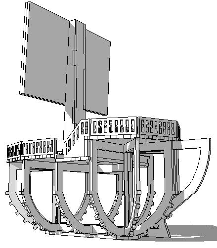
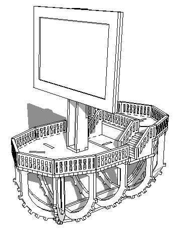
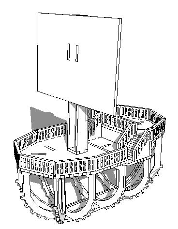
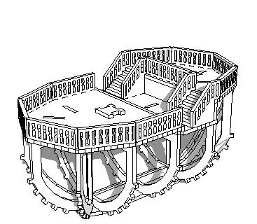
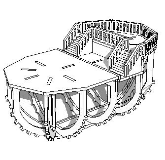
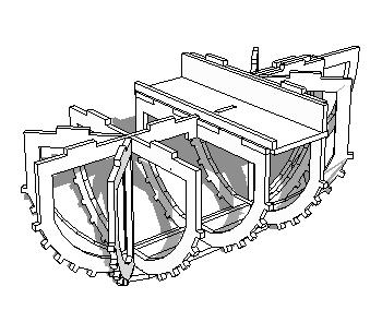
10 4. This tutorial shows how you can take a final product apart and layout a detailed step by step guide to constructing it. NB: This only works if you have correctly drawn all the pieces and grouped them so they can be flat packed for manufacture 5. Maximise the drawing clicking on the zoom extents tool. Then click on View Animation add scene 10


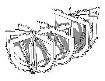
11 6. Click on the orbit tool. Then move around the boat slightly. Then click on View Animation Add scene 7. Click on the orbit tool. Then move around the boat slightly. Then click on View Animation Add scene 11


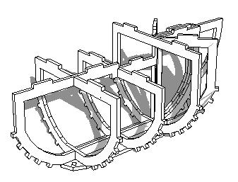
12 8. Click on the orbit tool. Then move around the boat slightly. Then click on View Animation Add scene Complete a 360 rotation all the way around your product. Adding a scene each time. The last scene should be a good view where you can see most of the product and its parts 12

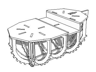
13 9. You are now going to take your product apart in reverse order with the last piece you would put on being the first one you will take off. 10. Using the select tool click on the first piece you are going to take off, it will indicate you have selected it by going blue. 11. Right click on the mouse and select hide. Then click on View Animation Add scene 13

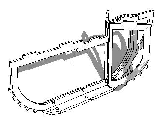
14 12. Using the select tool click on one of the next pieces you wish to take off. 13. You can take more that one piece of at a time. In the case of this product we are going to take whole strips off. 14. Hold the shift key down 15. Click on the other pieces that you wish to highlight to remove. 14
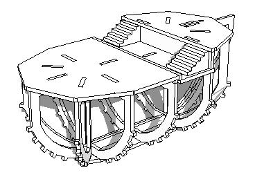
15 16. Right click on the mouse and select hide. Then click on View Animation Add scene 17. Using the select tool click the next pieces you wish to take off. Remember you can take more that one piece of at a time (follow step 12). 18. Right click on the mouse and select hide. Then click on View Animation Add scene 15
16 19. Repeat steps 17 and 18 on all the pieces until you have only one left remaining. You will probably have a lot of scenes at the top of your screen 16
17 17
18 18
19 19
20 20

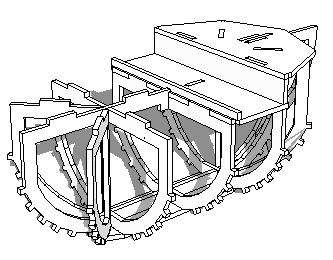
21 20. You will probably have a lot of scenes at the top of your screen 21. Starting with the furthest far right number this is the beginning of your step by step guide. Clicking from left to right will build your product. In this drawing I have changed the numbers so 1 is on the far right hand side. 22. Print screen each image and crop and place in your folder to complete your step by step guide. 21
Using Google SketchUp
 Using Google SketchUp Opening sketchup 1. From the program menu click on the SketchUp 8 folder and select 3. From the Template Selection select Architectural Design Millimeters. 2. The Welcome to SketchUp
SketchUp Training Notes By Professional CAD Systems Ltd Ph
 SketchUp Training Notes By Professional CAD Systems Ltd Ph 07 847 2268 Coffee Table: Using the Rectangle tool, draw a rectangle which is 1100mmx550mm to form the Top of the coffee table. You will need
Modeling an Airframe Tutorial
 EAA SOLIDWORKS University p 1/11 Difficulty: Intermediate Time: 1 hour As an Intermediate Tutorial, it is assumed that you have completed the Quick Start Tutorial and know how to sketch in 2D and 3D. If
Model House Exercise-( Extrude)
") -( Extrude) Prerequisite knowledge Focus of the lesson Commands Used This lesson requires an understanding of using the sketch commands including Inserting a new sketch Adding sketch geometry Understanding
-( Extrude) Prerequisite knowledge Focus of the lesson Commands Used This lesson requires an understanding of using the sketch commands including Inserting a new sketch Adding sketch geometry Understanding
Cube in a cube Fusion 360 tutorial
 Cube in a cube Fusion 360 tutorial n Before using these instructions, it is helpful to watch this video screencast of the CAD drawing actually being done in the software. Click to link to the video tutorial.
Creo Revolve Tutorial
 Creo Revolve Tutorial Setup 1. Open Creo Parametric Note: Refer back to the Creo Extrude Tutorial for references and screen shots of the Creo layout 2. Set Working Directory a. From the Model Tree navigate
SolidWorks Part I - Basic Tools SDC. Includes. Parts, Assemblies and Drawings. Paul Tran CSWE, CSWI
 SolidWorks 2015 Part I - Basic Tools Includes CSWA Preparation Material Parts, Assemblies and Drawings Paul Tran CSWE, CSWI SDC PUBLICATIONS Better Textbooks. Lower Prices. www.sdcpublications.com Powered
1. Creating geometry based on sketches 2. Using sketch lines as reference 3. Using sketches to drive changes in geometry
 4.1: Modeling 3D Modeling is a key process of getting your ideas from a concept to a read- for- manufacture state, making it core foundation of the product development process. In Fusion 360, there are
Sketch-Up Guide for Woodworkers
 W Enjoy this selection from Sketch-Up Guide for Woodworkers In just seconds, you can enjoy this ebook of Sketch-Up Guide for Woodworkers. SketchUp Guide for BUY NOW! Google See how our magazine makes you
Modeling Basic Mechanical Components #1 Tie-Wrap Clip
 Modeling Basic Mechanical Components #1 Tie-Wrap Clip This tutorial is about modeling simple and basic mechanical components with 3D Mechanical CAD programs, specifically one called Alibre Xpress, a freely
Product Modelling in Solid Works
 Product Modelling in Solid Works In the following exercise you will use solid works to construct the computer mouse shown opposite. In this exercise you will use a number of advanced features to achieve
Using Siemens NX 11 Software. The connecting rod
 Using Siemens NX 11 Software The connecting rod Based on a Catia tutorial written by Loïc Stefanski. At the end of this manual, you should obtain the following part: 1 Introduction. Start NX 11 and open
Siemens NX11 tutorials. The angled part
 Siemens NX11 tutorials The angled part Adaptation to NX 11 from notes from a seminar Drive-to-trial organized by IBM and GDTech. This tutorial will help you design the mechanical presented in the figure
CAD tutorial for the drinking straw support
 CAD tutorial for the drinking straw support Having tried a number of different designs, this one worked best on the greatest variety of glasses straight sided glass, angled glass and even a champagne flute.
Engineering & Computer Graphics Workbook Using SolidWorks 2014
 Engineering & Computer Graphics Workbook Using SolidWorks 2014 Ronald E. Barr Thomas J. Krueger Davor Juricic SDC PUBLICATIONS Better Textbooks. Lower Prices. www.sdcpublications.com Powered by TCPDF (www.tcpdf.org)
The Revolve Feature and Assembly Modeling
 The Revolve Feature and Assembly Modeling PTC Clock Page 52 PTC Contents Introduction... 54 The Revolve Feature... 55 Creating a revolved feature...57 Creating face details... 58 Using Text... 61 Assembling
EXERCISE ONE: BEACH BUGGY.
 EXERCISE ONE: BEACH BUGGY. Prerequisite knowledge Students should have completed Exercises from the file: Introduction to Assemblies Concept Mates Focus of lesson Commands Used This lesson will focus on
AEROPLANE. Create a New Folder in your chosen location called Aeroplane. The four parts that make up the project will be saved here.
 AEROPLANE Prerequisite Knowledge Previous knowledge of the following commands is required to complete this lesson. Sketching (Line, Rectangle, Arc, Add Relations, Dimensioning), Extrude, Assemblies and
Lab 3 Introduction to SolidWorks I Silas Bernardoni 10/9/2008
 1 Introduction This lab is designed to provide you with basic skills when using the 3D modeling program SolidWorks. You will learn how to build parts, assemblies and drawings. You will be given a physical
Table of Contents. Lesson 1 Getting Started
 NX Lesson 1 Getting Started Pre-reqs/Technical Skills Basic computer use Expectations Read lesson material Implement steps in software while reading through lesson material Complete quiz on Blackboard
Engineering & Computer Graphics Workbook Using SOLIDWORKS
 Engineering & Computer Graphics Workbook Using SOLIDWORKS 2017 Ronald E. Barr Thomas J. Krueger Davor Juricic SDC PUBLICATIONS Better Textbooks. Lower Prices. www.sdcpublications.com Powered by TCPDF (www.tcpdf.org)
10/14/2010. Chevy Malibu. Vehicle Design with Solidworks. Start SolidWorks Create a New SolidWorks Document. Miles, Rowardo B
 Chevy Malibu Vehicle Design with Solidworks Start SolidWorks Create a New SolidWorks Document Miles, Rowardo B 1 Click: Part and then OK Now you are ready to make a Part. 2 Right Toolbar: Document Properties:
Introduction to Circular Pattern Flower Pot
 Prerequisite Knowledge Previous knowledge of the sketching commands Line, Circle, Add Relations, Smart Dimension is required to complete this lesson. Previous examples of Revolved Boss/Base, Cut Extrude,
Diane Burton, STEM Outreach.
 123D Design Tutorial: LED decoration Before using these instructions, it is very helpful to watch this video screencast of the CAD drawing actually being done in the software. Click this link for the video
SolidWorks Tutorial 1. Axis
 SolidWorks Tutorial 1 Axis Axis This first exercise provides an introduction to SolidWorks software. First, we will design and draw a simple part: an axis with different diameters. You will learn how to
The project focuses on the design for a Pencil holder, but could be adapted to any simple assembly.
 Introduction - Teacher Notes Fig 1. The project focuses on the design for a Pencil holder, but could be adapted to any simple assembly. Pro/DESKTOP enables pupils (and teachers) to communicate and model
Assignment 12 CAD Mechanical Part 2
 Assignment 12 CAD Mechanical Part 2 Objectives In this assignment you will learn to apply the hidden lines, isometric snap, and ellipses commands along with commands previously learned.. General Hidden
Module 1G: Creating a Circle-Based Cylindrical Sheet-metal Lateral Piece with an Overlaying Lateral Edge Seam And Dove-Tail Seams on the Top Edge
 Inventor (10) Module 1G: 1G- 1 Module 1G: Creating a Circle-Based Cylindrical Sheet-metal Lateral Piece with an Overlaying Lateral Edge Seam And Dove-Tail Seams on the Top Edge In Module 1A, we have explored
Digital Camera Exercise
 Commands Used New Part This lesson includes Sketching, Extruded Boss/Base, Extruded Cut, Fillet, Chamfer and Text. Click File, New on the standard toolbar. Select Part from the New SolidWorks Document
CAD Orientation (Mechanical and Architectural CAD)
") Design and Drafting Description This is an introductory computer aided design (CAD) activity designed to give students the foundational skills required to complete future lessons. Students will learn all
Design and Drafting Description This is an introductory computer aided design (CAD) activity designed to give students the foundational skills required to complete future lessons. Students will learn all
2809 CAD TRAINING: Part 1 Sketching and Making 3D Parts. Contents
 Contents Getting Started... 2 Lesson 1:... 3 Lesson 2:... 13 Lesson 3:... 19 Lesson 4:... 23 Lesson 5:... 25 Final Project:... 28 Getting Started Get Autodesk Inventor Go to http://students.autodesk.com/
Pull Down Menu View Toolbar Design Toolbar
 Pro/DESKTOP Interface The instructions in this tutorial refer to the Pro/DESKTOP interface and toolbars. The illustration below describes the main elements of the graphical interface and toolbars. Pull
Wireless Mouse Surfaces
 Wireless Mouse Surfaces Design & Communication Graphics Table of Contents Table of Contents... 1 Introduction 2 Mouse Body. 3 Edge Cut.12 Centre Cut....14 Wheel Opening.. 15 Wheel Location.. 16 Laser..
When you complete this assignment you will:
 Objjectiives When you complete this assignment you will: 1. Set-up menus and drawing for designing modeling problems. 2. become familiar with the Sketch menu tools and commands. 3. Produce a three-dimensional
Drawing Layouts Paper space & Model Space
 Drawing Layouts Paper space & Model Space Users of Bricscad will have seen the tabs at the bottom left of the drawings area labelled: Model, Layout1, Layout2 but may not know how to use them or what they
AutoCAD 2D. Table of Contents. Lesson 1 Getting Started
 AutoCAD 2D Lesson 1 Getting Started Pre-reqs/Technical Skills Basic computer use Expectations Read lesson material Implement steps in software while reading through lesson material Complete quiz on Blackboard
Revit Structure 2013 Basics
 Revit Structure 2013 Basics Framing and Documentation Elise Moss Supplemental Files SDC P U B L I C AT I O N S Schroff Development Corporation Better Textbooks. Lower Prices. www.sdcpublications.com Tutorial
TOY TRUCK. Figure 1. Orthographic projections of project.
 TOY TRUCK Prepared by: Harry Hawkins The following project is of a small, wooden toy truck. This exercise will provide you with the procedure for constructing the various parts of the design then assembling
Create a Simple Architectural Structure (Architectural CAD)
") Description In this activity the teacher will demonstrate how to transform the 2D floor plan into a 3D structure, using the plan created in the Drawing of a Simple Building activity. Lesson Objectives
Description In this activity the teacher will demonstrate how to transform the 2D floor plan into a 3D structure, using the plan created in the Drawing of a Simple Building activity. Lesson Objectives
Appendix B: Autocad Booklet YR 9 REFERENCE BOOKLET ORTHOGRAPHIC PROJECTION
 Appendix B: Autocad Booklet YR 9 REFERENCE BOOKLET ORTHOGRAPHIC PROJECTION To load Autocad: AUTOCAD 2000 S DRAWING SCREEN Click the start button Click on Programs Click on technology Click Autocad 2000
Getting Started. Right click on Lateral Workplane. Left Click on New Sketch
 Getting Started 1. Open up PTC Pro/Desktop by either double clicking the icon or through the Start button and in Programs. 2. Once Pro/Desktop is open select File > New > Design 3. Close the Pallet window
Name: Date Completed: Basic Inventor Skills I
 Name: Date Completed: Basic Inventor Skills I 1. Sketch, dimension and extrude a basic shape i. Select New tab from toolbar. ii. Select Standard.ipt from dialogue box by double clicking on the icon. iii.
When you complete this assignment you will:
 Objjectiives When you complete this assignment you will: 1. sketch and dimension circles and arcs. 2. cut holes in the model using the cut feature of the extrusion command. 3. create Arcs using the trim
Autodesk Inventor. In Engineering Design & Drafting. By Edward Locke
 Autodesk Inventor In Engineering Design & Drafting By Edward Locke Engineering Design Drafting Essentials Working Drawings: Orthographic Projection Views (multi-view, auxiliary view, details and sections)
Drawing and Assembling
 Youth Explore Trades Skills Description In this activity the six sides of a die will be drawn and then assembled together. The intent is to understand how constraints are used to lock individual parts
SolidWorks Design & Technology
 SolidWorks Design & Technology Training Course at PHSG Ex 5. Lego man Working with part files 8mm At first glance the Lego man looks complicated but I hope you will see that if you approach a project one
PRODIM CT 3.0 MANUAL the complete solution
 PRODIM CT 3.0 MANUAL the complete solution We measure it all! General information Copyright All rights reserved. Apart from the legally laid down exceptions, no part of this publication may be reproduced,
Getting Started. Chapter. Objectives
 Chapter 1 Getting Started Autodesk Inventor has a context-sensitive user interface that provides you with the tools relevant to the tasks being performed. A comprehensive online help and tutorial system
Sheet Metal OverviewChapter1:
 Sheet Metal OverviewChapter1: Chapter 1 This chapter describes the terminology, design methods, and fundamental tools used in the design of sheet metal parts. Building upon these foundational elements
Adobe Photoshop CC 2018 Tutorial
 Adobe Photoshop CC 2018 Tutorial GETTING STARTED Adobe Photoshop CC 2018 is a popular image editing software that provides a work environment consistent with Adobe Illustrator, Adobe InDesign, Adobe Photoshop,
Chapter 2. Modifying, Extruding and Revolving the Sketches. Learning Objectives. Commands Covered AMMODDIM AMEXTRUDE AMREVOLVE
 Chapter 2 Modifying, Extruding and Revolving the Sketches Learning Objectives After completing this chapter, you will be able to: Modify the desired sketch using the AMMODDIM command. Extrude the desired
Introduction to IntelliCAD 6
 Introduction to IntelliCAD 6 These notes explain the basic concepts and techniques for doing 2D line drawings, with dimensions, arranged onto sheets for printing, using the 6.4 or 6.6 versions of IntelliCAD
Build the clerestory of Chartres Cathedral
 Build the clerestory of Chartres Cathedral Overview: Step 1. Create a new Design Layer Step 2. Build the wall Step 3. Build the lancets Step 4. Build the rose window Step 5. Build the rose window quatrefoils
Dean Muccio AutoCAD Interior Designer. for the. AutoCAD for Mac and PC SDC. Better Textbooks. Lower Prices.
 Dean Muccio AutoCAD 2020 for the Interior Designer AutoCAD for Mac and PC SDC P U B L I C AT I O N S Better Textbooks. Lower Prices. www.sdcpublications.com Powered by TCPDF (www.tcpdf.org) Visit the following
SolidWorks Navigation
 SolidWorks Basics SolidWorks Navigation Command Bar Feature Tree Model Window Simple Box Select the Front plane Create a new sketch Create a Center Rectangle from the origin Smart Dimension the length
AutoCAD Lab 1 Basics and Drawing Fundamentals. EGS 1007 Engineering Concepts and Methods
 AutoCAD Lab 1 Basics and Drawing Fundamentals EGS 1007 Engineering Concepts and Methods Will the Computer Ever REPLACE Pencil and Paper Drawings? Maybe someday When a computer becomes as light, small,
Introduction to solid modeling using Onshape
 Onshape is a CAD/solid modeling application. It provides powerful parametric and direct modeling capabilities. It is cloud based therefore you do not need to install any software. Documents are shareable.
Tutorial Building the Nave Arcade
 Tutorial: Digital Gothic AH C117B (Winter 2017) Tutorial Building the Nave Arcade Overview: Step 1: Determining and Drawing The Arch (Quinto Arch) Step 2: Extrude Molding Profile Step 3: Adding Walls Step
Sketch-Up Project Gear by Mark Slagle
 Sketch-Up Project Gear by Mark Slagle This lesson was donated by Mark Slagle and is to be used free for education. For this Lesson, we are going to produce a gear in Sketch-Up. The project is pretty easy
Sheet Metal OverviewChapter1:
 Sheet Metal OverviewChapter1: Chapter 1 This chapter describes the terminology, design methods, and fundamental tools used in the design of sheet metal parts. Building upon these foundational elements
Introduction to Autodesk Inventor for F1 in Schools (Australian Version)
") Introduction to Autodesk Inventor for F1 in Schools (Australian Version) F1 in Schools race car In this course you will be introduced to Autodesk Inventor, which is the centerpiece of Autodesk s Digital
Introduction to Autodesk Inventor for F1 in Schools (Australian Version) F1 in Schools race car In this course you will be introduced to Autodesk Inventor, which is the centerpiece of Autodesk s Digital
Engineering Innovation Center Autodesk Fusion 360
 Engineering Innovation Center Autodesk Fusion 360 Introduction The Engineering Innovation Center is a large academic maker space with plenty of tools and equipment. In order to use these items you must
Inventor-Parts-Tutorial By: Dor Ashur
 Inventor-Parts-Tutorial By: Dor Ashur For Assignment: http://www.maelabs.ucsd.edu/mae3/assignments/cad/inventor_parts.pdf Open Autodesk Inventor: Start-> All Programs -> Autodesk -> Autodesk Inventor 2010
Dean Muccio. AutoCAD 2018 for the. Interior Designer. AutoCAD for Mac and PC SDC. Better Textbooks. Lower Prices.
 Dean Muccio AutoCAD 2018 for the Interior Designer AutoCAD for Mac and PC SDC P U B L I C AT I O N S Better Textbooks. Lower Prices. www.sdcpublications.com Powered by TCPDF (www.tcpdf.org) Visit the following
Principles and Applications of Microfluidic Devices AutoCAD Design Lab - COMSOL import ready
 Principles and Applications of Microfluidic Devices AutoCAD Design Lab - COMSOL import ready Part I. Introduction AutoCAD is a computer drawing package that can allow you to define physical structures
Designing in the context of an assembly
 SIEMENS Designing in the context of an assembly spse01670 Proprietary and restricted rights notice This software and related documentation are proprietary to Siemens Product Lifecycle Management Software
Clock Exercise (Inserting Planes)
") Clock Exercise (Inserting Planes) Prerequisite Knowledge To complete this exercise you will need to be familiar with Sketching, Applying relations, Extrude Boss/ Base, Extrude cut, Applying Textures, Renaming
Clock Exercise (Inserting Planes) Prerequisite Knowledge To complete this exercise you will need to be familiar with Sketching, Applying relations, Extrude Boss/ Base, Extrude cut, Applying Textures, Renaming
Drawing a Living Room and Family Room Floorplan
 Appendix C Drawing a Living Room and Family Room Floorplan In this chapter, you will learn the following to World Class standards: Draw a Living Room and Family Room Floorplan Draw the Walls and Stairs
Introducing SolidWorks
 Introducing SolidWorks SAAST Robotics 2008 SolidWorks Software Visually-based 3-D Mechanical design software Engineers and Designers use it to: Quickly sketch out ideas Experiment with features, dimensions
Introduction to Sheet Metal Features SolidWorks 2009
 SolidWorks 2009 Table of Contents Introduction to Sheet Metal Features Base Flange Method Magazine File.. 3 Envelopment & Development of Surfaces.. 14 Development of Transition Pieces.. 23 Conversion to
Revit Structure 2014 Basics
 Revit Structure 2014 Basics Framing and Documentation Elise Moss Authorized Author SDC P U B L I C AT I O N S Better Textbooks. Lower Prices. www.sdcpublications.com Powered by TCPDF (www.tcpdf.org) Visit
Computer Assisted Drafting (CAD) Level I & II
 Level I & II") Computer Assisted Drafting (CAD) Level I & II Program Description: Level I The Computer Assisted Drafting program prepares students for successful careers beginning as entry level design drafters in Architectural,
Computer Assisted Drafting (CAD) Level I & II Program Description: Level I The Computer Assisted Drafting program prepares students for successful careers beginning as entry level design drafters in Architectural,
Tools for Design. with VEX Robot Kit: Randy H. Shih Oregon Institute of Technology SDC PUBLICATIONS
 Tools for Design with VEX Robot Kit: AutoCAD 2011 and Autodesk Inventor 2011 2D Drawing 3D Modeling Hand Sketching Randy H. Shih Oregon Institute of Technology INSIDE: SUPPLEMENTAL FILES ON CD SDC PUBLICATIONS
CAD/CAM Lamp Project using 2D Design and the X-660 Laser Cutter
 CAD/CAM Lamp Project using 2D Design and the X-660 Laser Cutter Paul Tate 2008 Booklet Version 2 Getting Started the preliminaries The Laser cutter which is going to cut out your acrylic bases and polypropylene
Constructing a Wedge Die
 1-(800) 877-2745 www.ashlar-vellum.com Using Graphite TM Copyright 2008 Ashlar Incorporated. All rights reserved. C6CAWD0809. Ashlar-Vellum Graphite This exercise introduces the third dimension. Discover
and Engineering Graphics
 SOLIDWORKS 2018 and Engineering Graphics An Integrated Approach Randy H. Shih SDC PUBLICATIONS Better Textbooks. Lower Prices. www.sdcpublications.com Powered by TCPDF (www.tcpdf.org) Visit the following
06/17/02 Page 1 of 12
 Understanding the Graphical User Interface When you start AutoCAD, the AutoCAD window opens. The window is your design work space. It contains elements that you use to create your designs and to receive
Building a Greek pool. This lesson will continue with the push/pull and off set tools. You will also be using exact measurements and changing the
 Building a Greek pool. This lesson will continue with the push/pull and off set tools. You will also be using exact measurements and changing the sides of a polygon. A new tool will be introduced called
Hydro Hull. Chapter 21. Boat. A. Save as "HYDRO". Step 1. Open your HULL MID PLANE file (Chapter 2).
.") Chapter 21 Boat Hydro Hull A. Save as "HYDRO". Step 1. Open your HULL MID PLANE file (Chapter 2). Step 2. Click File Menu > Save As. Step 3. Key-in HYDRO for the filename and press ENTER. B. Delete Loft1,
Chapter 21 Boat Hydro Hull A. Save as "HYDRO". Step 1. Open your HULL MID PLANE file (Chapter 2). Step 2. Click File Menu > Save As. Step 3. Key-in HYDRO for the filename and press ENTER. B. Delete Loft1,
Advance Concrete. Tutorial
 Advance Concrete Tutorial Table of contents About this tutorial... 9 How to use this guide... 10 Lesson 1: Creating a building grid... 11 Step 1: Create a default building grid... 11 Step 2: Set the distances
DEPARTMENT OF MECHANICAL AND INDUSTRIAL ENGINEERING NORTHEASTERN UNIVERSITY
 DEPARTMENT OF MECHANICAL AND INDUSTRIAL ENGINEERING NORTHEASTERN UNIVERSITY CAPSULE PROGRAM Funded by NSF grant #0833636 Tutorial 02 3D Part Modeling SolidWorks 2010 Copyright 2010 Prof. Zeid 3D Part Modeling
SOLIDWORKS 2015 and Engineering Graphics
 SOLIDWORKS 2015 and Engineering Graphics An Integrated Approach Randy H. Shih SDC PUBLICATIONS Better Textbooks. Lower Prices. www.sdcpublications.com Powered by TCPDF (www.tcpdf.org) Visit the following
Solidworks Tutorial Pencil
 The following instructions will be used to help you create a Pencil using Solidworks. These instructions are ordered to make the process as simple as possible. Deviating from the order, or not following
Copyrighted. Material. Copyrighted. Material. Copyrighted. Material. Copyrighted. Material
 ENGINEERING & COMPUTER GRAPHICS WORKBOOK Using SolidWorks 2008 Ronald E. Barr Thomas J. Krueger Theodore A. Aanstoos Davor Juricic SDC PUBLICATIONS Schroff Development Corporation www.schroff.com Better
Sash Clamp. Sash Clamp SW 2015 Design & Communication Graphics Page 1.
 Sash Clamp 1 Introduction: The Sash clamp consists of nine parts. In creating the clamp we will be looking at the improvements made by SolidWorks in linear patterns, adding threads and in assembling the
Straw support Fusion 360
 Straw support Fusion 360 Before using these instructions, watch the video screencast of the CAD drawing actually being done in the software. Click this link for video tutorial This design works on a variety
Creo Extrude Tutorial 2: Cutting and Adding Material
 Creo Extrude Tutorial 2: Cutting and Adding Material 1. Open Creo Parametric 2. File > Open > extrudeturial (From Creo Extrude Tutorial 1) 3. Cutting Material a. Click Extrude Icon > Select the following
Design for fireplace setting by Ross Ubergang rossu.com.au. gcadplus User Guide v gcad +
 This chapter focuses on the use of common drawing tools needed to create typical landscape drawings. You will learn to use these draw tools by making an accurate, full-size model of a proposal for a space
UNIT 11: Revolved and Extruded Shapes
 UNIT 11: Revolved and Extruded Shapes In addition to basic geometric shapes and importing of three-dimensional STL files, SOLIDCast allows you to create three-dimensional shapes that are formed by revolving
Ornamental Pro 2004 Instruction Manual (Drawing Basics)
") Ornamental Pro 2004 Instruction Manual (Drawing Basics) http://www.ornametalpro.com/support/techsupport.htm Introduction Ornamental Pro has hundreds of functions that you can use to create your drawings.
Ornamental Pro 2004 Instruction Manual (Drawing Basics) http://www.ornametalpro.com/support/techsupport.htm Introduction Ornamental Pro has hundreds of functions that you can use to create your drawings.
How to draw the CB South Kerf Bent Clock:
 How to draw the CB South Kerf Bent Clock: Open sketch up, use the Product Design and Woodworking template with Inches as the units. If there is a person in the drawing space, you can delete him/her. When
gmodeller : User Guide
 gmodeller : User Guide CONTENTS 1. gmodeller HOW TO MODEL YOUR BUILDING 1.1. Introduction 1.2. Level of detail required 1.3. Revising Floor Plans 1.3.1. Simplifying 1.3.2. Zoning 1.3.3. 2D CAD imports
Version 8 Tutorial
 Version 8 Tutorial 800-989-4243 214-340-9436 support@vertigraph.com www.vertigraph.com 1 Table of Contents A. Overview... 4 B. About the SiteWorx/OS Window... 4 C. File Types Raster, Vector and PDF...
Pro/DESKTOP Tutorial Drafting Bow Compass
 Pro/DESKTOP Tutorial Drafting Bow Compass Michael Flowers 2005 1 Objectives: To develop confidence with the Pro/DESKTOP software. To learn to utilize extrude, project, revolve, round, and chamfer features.
Creating a 3D Assembly Drawing
 C h a p t e r 17 Creating a 3D Assembly Drawing In this chapter, you will learn the following to World Class standards: 1. Making your first 3D Assembly Drawing 2. The XREF command 3. Making and Saving