Drawing output in imos ix 2017 SR2. Date of creation: March 2018; last changes Version used: ix 2017 SR2
|
|
|
- Abel Norton
- 5 years ago
- Views:
Transcription

1 Drawing output in imos ix 2017 SR2 Date of creation: March 2018; last changes Version used: ix 2017 SR2
2 We make every effort to ensure the content of this document is complete, accurate and up to date. However, continuous development of the described software means it is not possible to guarantee the information is complete, accurate and up to date at all times. We shall endeavor to incorporate in subsequent versions of this document corrections to any errors or omissions we either become aware of or which are reported to us. imos does not accept any liability for direct, indirect or consequential damages or loss resulting from the use of or failure to use the information provided or resulting from the use of incorrect or incomplete information. The descriptions in this document are subject to change without notice imos AG. All rights reserved. This document was produced by the imos AG Planckstraße Herford
3 Content 1. Foreword Part Views Workflow Understanding how it works and settings Dimensioning principles Examples ( best practices ) Default settings Dimensioning Positioning and quadrant/origin Order of dimension chains Grouping Dimensioning points Filter conditions Optimizing group Information about generating panels Indexing / annotate drawings Workflow Placing & scaling Configuration indexing Machining and edge indices Table styles Creating/using detail blocks Annotate view Workflow Understanding how it works and settings Example Creating annotation blocks (DWG) Special characteristic Creating blocks in imos OEM (AutoCAD OEM)
4 4.4.3 Creating blocks in imos CAD (AutoCAD full version) Borders Differences to SR Loading & editing drawing border Editing drawing border Save border Configure attributes Save changes in drawing border Defining a viewport View direction Visual Styles Scale Label viewport Creating new drawing borders Creating and editing page setups Customer paper sizes Document Manager Overview Call up and workflow Understanding how it works and settings Layouts Output formats Viewports Functions available depending on the object level File name Best practice Output format for tall cabinets Adapt fuzzy images via reports of PC3 files - suitable paper size Message informing it is not necessary to produce a drawing for the selected objects Additional information imos attributes Information text formats
5 7.2.1 Defaults Drillings / grooves Lineboring Rectangular Pockets / Circular Pockets Edges Inside contours Attributes to define detail blocks This document is based on the imos version ix 2017 SR2. 5
6 1. Foreword This document contains a description of the new functions relating to the output of drawings included in the imos versions ix 2017 SR1 SR2. 2. Part Views In imos ix 2017 part dimensioning and the underlying dimensioning principle have been developed from scratch. The dimensioning principle of the new part dimensioning function (part views) is located in the Element Manager. Here it is possible to determine precisely which machining types are to be dimensioned and how. In other words, it is possible to configure the dimensioning style, dimensioning type, positioning and the dimensioning objects according to requirements. At the same time a view of each side of the part in which a machining type is assigned is created and dimensioned. Redundant dimensions are eliminated automatically. Workflow Workflow

7 2.1 Workflow The function to create dimensioned part views is called up via the ribbon menu Drawing views / Part views. Workflow Workflow

8 When the function is called, the dialog box Section Options opens. In addition, a prompt is displayed requesting you to select an object. You can directly select a part to be dimensioned. In this case, imos uses the last used dimensioning principle. Note If the function is started for the first time you must first press ENTER before you pick a part. Workflow Workflow
9 The Element Manager then displays the dimensioning principles and it is possible to select a principle. After you click Apply you must then select the corresponding part in the drawing. That creates dimensioned part views, which can then be dropped into the model space. Workflow Workflow

10 2.2 Understanding how it works and settings Dimensioning principles It is possible to (fully) dimension a drawing of a part via the dimensioning principle in the Element Manager. The individual positions to be dimensioned are assembled and added to a dimension/dimension chain. No limits are placed on the number of dimensions/dimension chains it is possible to define in a principle. It is possible to define the appearance (dimension type, dimension style) and position (inside, outside, left, right, etc.) of each dimension/dimension chain. Workflow Understanding how it works and settings
11 Default settings The general setting options are contained in the Default settings of the dimensioning principles. Description Type Offset dimension to object Offset dimension to dimension line Position / origin Free editable text field Defines the type for which this dimensioning principle is valid. Part dimensioning must currently be set here. Defines the spacing between the part and the first dimension line in mm. Defines the spacing between two dimension lines in mm. Defines the origin to which the dimension refers. Workflow Understanding how it works and settings


12 Dimensioning The individual dimensions are defined below the node Dimensioning. Each row in the grid of a dimensioning principle defines a dimension chain. At the same time, it is also possible to create groups and use these to influence the appearance of the dimensioning. Tip It is possible to copy, insert, duplicate and delete rows via the sandwich button. Workflow Understanding how it works and settings
13 Sequence Determines the sequence in which the dimensions/dimension chains are arranged (1 to n). The first row ( 1 ) is the most inner dimensioning/dimension chain and the last row ( n ) is the furthest away. Of course, irrespective of this sequence inside dimensions are positioned inside of outside dimensions. Description Dimension type Dimension Style Free editable text field Defines the dimension type (baseline, chain, ordinate dimensioning, etc.) and if the witness lines are to be drawn up to the machining detail to be dimensioned or end at the boundaries of the part (with a small gap, which must be set in the AutoCAD dimension style). Assigns an AutoCAD dimension style to the dimension/dimension chain. Workflow Understanding how it works and settings
14 Grouping When dimensioning is being defined, an option is available to group the dimensions according to certain criteria. "Grouping" creates a corresponding number of dimension chains, see Grouping rules. Position This is where it is defined where the dimensioning/dimension chain is to be applied (inside, outside, left, right, etc.). A couple of examples for different position settings for a drilling with X = 50, Y = 100 in a 600x400mm panel, in which Position/origin is set Center center : Outside, right : The dimension goes from Y= 0 to Y = 100 to the right of the right edge of the part. Workflow Understanding how it works and settings
15 Inside, top : The dimension goes from X = 0 to X = 50 in the part, but above the machining detail. Inside, to origin, t/b. As the origin is above the machining detail (has a greater Y value), to origin means the same as to top for THIS machining step and the same dimension results as in the previous case. Outside the nearest sides : The drilling is nearer to the left than the right side and nearer to the bottom than the top side; consequently, a dimension is generated below and left of the part. When Outside the nearest sides is selected the general rule applicable to linear dimensions is that dimensioning is applied in X AND Y directions; however, in all other cases just one dimension is created in X OR Y direction. Workflow Understanding how it works and settings
16 Optimizing group Optimizing in this case refers only to leaving out redundant dimensions. For example, if five drillings have the Y-coordinates 100 normally just one dimension should be created and not five. In fact, five are initially created internally - and then four are omitted. You can further influence this with the setting Optimizing group, because two dimensions are never regarded as redundant if they are in different optimizing groups. Dimensions with different styles are also never regarded as redundant! Do not under any circumstances mistake optimizing groups for grouping, they are both completely separate! Dimensioning points Filter Conditions Defines which points are to be included. Further restricts the selection of points captured via conditions. Workflow Understanding how it works and settings


17 Grouping rules Radius, baseline and angle dimensioning contain no chains; consequently, it is always assumed in the following that the dimension type in all principles is set as chain dimensioning or ordinate dimensioning. Dimensions from different dimensioning rows are never chained in the principle; in other words, there are at least as many dimension chains as there are dimensioning rows. However, due to grouping there can be more dimension chains than rows! If one dimension is above and the other below, they are never chained. If the value is Standard, then all dimensions from this dimensioning are chained. The values By radius / By X / By Y / By Z mean the dimensions will be chained if the corresponding value is matched. This refers to the X / Y / Z of the machining in the part. Workflow Understanding how it works and settings
18 When By type, radius, depth and X or Y are chosen, the first three values between two dimensions must match for them to be chained. The type is drilling, circular pocket, groove, inner contour, etc. At the same time, for example, a distinction is made between individual drillings and those in workgroups. Moreover, new chains are created for machining procedures with completely different coordinates. Grouping has two effects: For the setting Continuous dimension or Ordinate dimension : The dimensions belonging to a chain are in a straight line. If there is another chain, which would collide with this one, this is pulled further outward. For the setting Continuous dimension : The chain is extended up to the edge. If, for example, the chain consists of the dimensions and below the part another dimension or even 350 part width is added. Which of the two directions is extended depends on Position/Origin. Workflow Understanding how it works and settings

19 In contrast, the optimizing group (see 2.3.8) affects neither the number of chains nor the chains at the edge extension but rather only if dimensions are omitted as redundant Dimensioning points It is possible to set via the submenu which points of each dimensioning/dimension chain are to be captured. These can be further restricted via Filter Conditions. Workflow Understanding how it works and settings
")
20 2.3 Examples ( best practices ) In the following, succinct examples are provided to explain the different setting options for dimensioning Default settings You begin initially with an empty principle or rather you create a new principle and all existing settings are deleted. The following settings are then made below Default settings: Workflow Examples ( best practices )
21 2.3.2 Dimensioning Add a dimensioning via the + button. Select Baseline dimensioning for the Dimension type Select IMOS_DIM as Dimension style Leave Grouping set to Standard Set Position to Outside the nearest sides In the Optimizing group the setting should be 0 Save the principle and carry out an initial test on an example part. (for example on a case partition).. Workflow Examples ( best practices )

22 To do so, call up the function Part views in the ribbon Drawing Views and press ENTER to confirm. Workflow Examples ( best practices )

23 Then select the newly created dimensioning principle in the Element Manager; click Apply to exit the Element Manager again. Then pick the part in the drawing for which the part view is to be created. Surprisingly, you obtain a non-dimensioned part view. Workflow Examples ( best practices )

24 The reason is that in the dimensioning principle you merely set how the dimension chain is to look and how it is to be positioned. You did not set what is to be dimensioned. Consequently, this is still to be set in the dimensioning principle. To do so, click the red + button in the dimensioning principle. Now you can add so-called dimensioning points. They are the points that are to be captured in the dimension chain. Now select Part size in the combo box Dimensioning points. This is how you obtain the outside dimensions of the part: Save the changes and then test the principle again. You will get the result shown at the left. Workflow Examples ( best practices )


25 Note Here visualization is 1:1 in the model space. If the scale is changed, you will need to update the section. That results in the dimension lines adapting to one another. Workflow Examples ( best practices )
. There is no lateral dimensioning (Y values).")
26 2.3.3 Positioning and quadrant/origin To understand the position settings, first change the position setting in the dimensioning principle from Outside the nearest sides to Outside, top. As a result, you will see that there are only dimensions above the part views (X values). There is no lateral dimensioning (Y values). That is because the dimension chain position has now been forced outside and to the top. To now also obtain Y values you will need to create a second dimension chain whose position is set, for example, to Outside, left. Workflow Examples ( best practices )

27 To create a second dimension chain duplicate the existing one via the sandwich button at the end of the row. A new row is created with precisely the same settings and dimensioning points. Alter the position of this row to Outside, left. The next test will then deliver the following result. Workflow Examples ( best practices )
: Create a new dimensioning principle for this part by copying the newly")
28 The connection between positioning and origin is shown below based on a straightforward part. The part has the dimensions 300x500x19 with a drilling (x=120; y=200): Create a new dimensioning principle for this part by copying the newly created principle. Workflow Examples ( best practices )

29 Then extend the new principle so that drillings are also captured. To do so, insert two new dimensioning lines. Set the dimension type for both lines to Chain up to machining Set the position for the first line to Inside, to origin, l/r and for the second line to Inside, to origin, t/b That means to say: Dimension drillings inside and align the dimension chains towards the origin. Set the dimensioning points to Drilling insertion point As a result you obtain the following dimensioning. Workflow Examples ( best practices )
30 If you change the position in the dimensioning principle from Inside, to origin to Inside, away from origin, the dimension chains are drawn away from the origin. Workflow Examples ( best practices )

31 You can see how the settings affect the origin, if you change the setting from Center center to Left top Workflow Examples ( best practices )
32 or change the origin to Right bottom : This allows you to precisely control in which direction the dimensions are to be drawn. Workflow Examples ( best practices )

33 2.3.4 Order of dimension chains Note As a rule, the dimensions are defined from inside to outside. The first line in the dimensioning principle defines the most inner dimension and the last line defines the most outer dimension. Consequently, it makes sense, for example, to define the part dimensions as the last line in the principle and position the machinings that are inside a part further up. Workflow Examples ( best practices )

34 If you again use the dimensioning principle from the example (Start_1) and set the positioning settings for the drillings from Inside... to Outside..., then you will recognize that the order Outside needs to be adapted in the principle. Workflow Examples ( best practices )

35 If you have now adapted the order you will obtain the following result: Workflow Examples ( best practices )
36 2.3.5 Grouping Grouping settings make it possible to group machinings according to certain criteria. Each group is then dimensioned by a dedicated dimension chain. To make this setting clearer, insert further drillings in X and Y in the test part: Workflow Examples ( best practices )
: Workflow Examples ( best practices")
37 First of all, take a look at the result with the following dimensioning principle (origin = Right bottom ): Workflow Examples ( best practices )

38 Now change the grouping of Y dimensions ( Outside, left ) of the drillings from Standard to By Y. You can see by the result that now three dimension chains have been created instead of one dimension chain. A dimension chain has been created for each different Y value: Workflow Examples ( best practices )

39 Change the settings for the X values of the drillings and use By X for grouping. As a result you also obtain a discrete dimension chain for each different X value of the drillings. Workflow Examples ( best practices )

40 Instead of X/Y values it is also possible to group By radius, for example. To test this setting you must assign different radii to the drillings in the test part: Set the grouping for the drillings to By radius in the dimensioning principle so that you can see that drillings with identical radii are grouped together in their own dimension chain. Workflow Examples ( best practices )
41 The other groupings ( By Z, By type, radius, depth and X or Y ) behave correspondingly! Workflow Examples ( best practices )
 to a dimensioning line via the + button.")
42 2.3.6 Dimensioning points In the previous examples, only one dimensioning point has been defined per dimensioning line. However, it is also possible to add several dimensioning points (drillings, lineborings, grooves, etc.) to a dimensioning line via the + button. Now add the dimensioning points for the grooves to the first two dimensioning lines for the drillings: Workflow Examples ( best practices )

43 Of course, you will have to add a groove to the test part so that you are able to see the effect this has: Workflow Examples ( best practices )
44 The result is that the groove is now also dimensioned in the dimension chain of the drillings. Workflow Examples ( best practices )

45 However, the present settings mean that only X aligned grooves are dimensioned. If you create and align a groove in Y direction it will not be dimensioned. The reason for this is the setting of the dimensioning points. The settings made in the dimensioning principle were such that the Groove width is to be dimensioned Outside, left and the Groove length Outside, top. With a groove positioned in Y direction both dimensions would result in 0 and would not be displayed as a consequence. Workflow Examples ( best practices )


46 Therefore, it is recommended that you always set the lengths and widths in a dimension chain when defining the dimensioning points. That ensures that the lengths and widths are always dimensioned no matter what the alignment. Tip To prevent the dimensionings being grouped, you will need to set the grouping for all dimensionings back to Standard again in the dimensioning principle used. Workflow Examples ( best practices )
: How filter conditions work will be explained in the following using the drillings as an example.")
47 2.3.7 Filter conditions Define the dimensioning points that are to capture machinings with a dimension chain. These can be further refined with filter conditions (for example, diameter, insertion points, etc.): How filter conditions work will be explained in the following using the drillings as an example. First, create two conditions for drillings. One for Drillings less or equal to 5mm and one for Drillings greater than 5mm. Click the [ ] button in the combo box to access the conditions principles: Workflow Examples ( best practices )


48 In the Conditions principles, first create a new principle with the name Drilling_less_equal_05 and select the machining PXM- Drill as the Type. In the submenu Conditions create an AND condition with the following settings; then save the principle: Workflow Examples ( best practices )
49 Create a second condition Drilling_greater_05 with the following settings. Save the principle, then click Apply : Workflow Examples ( best practices )


50 You are now back in the dimensioning principle again; here you see that Drilling_greater_05 is entered in the Filter Condition field. Add the same filter condition for the drillings to the second dimension chain of the dimensioning principle. Workflow Examples ( best practices )

51 Save and then test the dimensioning principle. As you can see, only drillings are dimensioned that are greater than 5mm. Add two new dimensioning lines for the drillings to the dimensioning principle. Steps Create a new dimensioning line via the + symbol below Dimensioning Select dimension type, dimension style and position via the pull-down menu Open the submenu dimensioning point, then define a new dimensioning point via the + symbol Define the dimensioning point (object) and the filter condition via the pull-down menu Move the new dimensioning line to the top of the list Workflow Examples ( best practices )


52 See the graphics below for the definition of the new dimensioning lines: As a result you obtain the following output: As you can see, the drillings with a diameter less or equal to 5mm are dimensioned on the inside. Workflow Examples ( best practices )

53 2.3.8 Optimizing group The optimizing group affects the behaviour regarding the omission of dimensions. All dimensions in the same Optimizing group are checked for redundancy and omitted as the case may be. This is shown clearly in the following example: Create a new dimensioning principle containing two dimensioning lines. Define only drillings (without filter conditions) in the dimensioning lines. One dimensioning line should be dimensioned Outside, left, the other Outside, right. Both dimensioning lines are assigned to the same optimizing group ( 0 in this case). Test the principle. You can see that only the left dimension chain has been created. You are entitled to expect that two dimension chains would be created. One should be on the right, the other on the left. However, as both dimension chains are in the same optimizing group, imos omits the right chain completely because this would have contained redundant dimensions. Workflow Examples ( best practices )
54 Nevertheless, if you wish to force both dimension chains to be created in all cases, then you will need to assign one of the dimension chains to another optimizing group. To do so, all you need to do is simply enter a different number in the Optimizing group field. Workflow Examples ( best practices )

55 2.3.9 Information about generating panels The number of generated panels when creating part views is determined according to the machinings of the part and according to the dimensioning points. For example, if there are machinings from the top and bottom in the part then two panels are always generated with a top view and a bottom view respectively. Workflow Examples ( best practices )

56 If the Partsize is defined as the dimensioning point, then at least one panel is always generated for the side view and the top view. Workflow Examples ( best practices )
57 3. Indexing / annotate drawings In addition to annotating plan views, views and sections, an indexing function has been implemented especially for the new part views. This includes all machining types and edges. Identical machining types and edges receive the same index. This is then mapped in a table with the corresponding information about machinings and edges. This ensures the part views and dimensions remain visible and are not concealed by superimposed info texts. It is also possible to attach an annotation principle when calling up the indexing function via ENTER. That means it is possible to display detail symbols for custom machinings (for example, countersink or step drillings), which are also indexed. These symbols are displayed only if a part is assigned a corresponding machining. Workflow Examples ( best practices )
58 Note The new annotation principle serves to annotate plan views, views and sections. The annotate and index part commands have been allocated their own function calls (see next chapter); they use the annotation principle only to display machining details. Indexing of part machinings and edges is executed independent of the annotation principle. Indexing of part machinings and edges is executed independent of the annotation principle. The configuration is implemented using the file imosdimindex.dwg. It is stored in <imos>\library\attdwg\. Workflow Examples ( best practices )
 you must access the corresponding command Part Annotation via the ribbon menu: After calling up the function, the user is offered additional options via the AutoCAD command line.")
59 3.1 Workflow Precondition A part view must be generated before a part can be annotated. Annotating or rather indexing of machinings and edges when dimensioning a part (see chapter. ) you must access the corresponding command Part Annotation via the ribbon menu: After calling up the function, the user is offered additional options via the AutoCAD command line. Workflow Workflow
60 The following options are available for selection: a) Indexing with the last used annotation principle b) Indexing without additional annotation principle [-] c) Indexing with previously selected annotation principle ENTER Option A) you do not have to enter any further details. Instead you can directly select the part panels to be indexed. In this case the last used annotation principle is automatically applied in addition to indexing. Indexing only will be implemented if no annotation principle was selected previously. Workflow Workflow
![Option B) [-] an indexing step is carried out without](/docs-images/90/103487057/images/61-2.jpg "additional annotation (detail blocks).")
61 Option B) [-] an indexing step is carried out without additional annotation (detail blocks). Workflow Workflow


62 Option C), after conforming with ENTER, first the Element Manager opens. Here you select an annotation principle that has been created specifically for annotating parts. After you click Apply select the corresponding part panels in the CAD system that are to be indexed. In addition to indexing, the detail blocks created in the annotation principle for the applicable machinings are also displayed. Note You find a detailed description about the definition of the detail blocks, respectively the annotation principles in chapter 4.2 and 7.2. Workflow Workflow


63 3.2 Placing & scaling It is then still possible to manually move the generated annotation blocks and detail blocks retrospectively to the required position as well as use the AutoCAD function Scale to size them accordingly. Workflow Placing & scaling
 Table styles (_TABLESTYLE) Workflow Configuration")
64 3.3 Configuration indexing Indexing settings are defined using the file imosdimindex.dwg in the directory <Library>\AttDWG. This contains: Machining and edge indices (style, numbering, info text format) Table styles (_TABLESTYLE) Workflow Configuration indexing

65 3.3.1 Machining and edge indices When you open the imosdimindex.dwg it contains machining indices for drilling, lineboring, groove, macro/rectangular pocket, circular pocket and inner contour as well as an edge index. Workflow Configuration indexing
 (see chapter 7.")
66 It is possible to define the color, text style, size, index numbering and the info text format via Properties of an index (right-click Properties) (see chapter 7.2 Workflow Configuration indexing

67 3.3.2 Table styles It is equally possible to adapt the composition of indexing tables. You can adapt text styles, sizes and colors as well as the title and column headers. Table styles are stored in the imosdimindex.dwg. The name of the table style for machinings is imosdimindex, the table style for edges imosedgeindex. The best way to adapt a table style is as follows: 1. In the open imosdimindex.dwg call up the function TABLE. Workflow Configuration indexing

68 2. Select the table style that is to be edited and click OK to insert it into the drawing. Select the table if you wish to edit it. In other words, you can edit the title and the columns as well as the color and the text styles. Note When you select a table in the drawing the composition of the ribbon menu changes to offer you functions that will allow you to edit the table. Workflow Configuration indexing

69 3. To edit the table style, call up the AutoCAD function TABLE STYLE. 4. Now select the table style to be changed and click the Modify button. Workflow Configuration indexing

70 5. In the dialog box that opens click the button containing the x (1) to delete the Starting table. 6. Click the adjacent button (2) to define a new Starting table. 7. Now pick the adapted table in the CAD area: The altered table is now saved as the Starting table. 8. Click OK and Close to close the dialog box. 9. Use the keyboard shortcut CTRL+S to save the changes in the imosdimindex.dwg. 10. Close the DWG. Workflow Configuration indexing

71 3.3.3 Creating/using detail blocks How to create and edit detail blocks is described in chapter. 0: Workflow Configuration indexing
72 Creating annotation blocks (DWG). Workflow Configuration indexing

73 4. Annotate view imos X 2017 SR1 offers a new function to annotate plan views, views and sections. Using the new annotation principle it is possible to define precisely how a section is to be annotated. In this case DWG blocks serve as annotation, which can be created or adapted to suit user-specific requirements. It is possible to use pure texts, imos attributes, symbols through to dynamic blocks. With this function it is possible to annotate a whole section with a single command. 4.1 Workflow Precondition It is only possible to annotate existing sections (for example a 2D plan view)! The annotation function for views is accessed via the ribbon menu Drawing views -> Annotate view. Workflow Workflow


74 When the function is called up the Element Manager opens and it is possible to select an annotation principle. After you click Apply select the corresponding section and the section will be annotated accordingly. Tip If the annotation is too big or too small, it can be scaled using the corresponding AutoCAD function. To do so simply select the required scale in the bottom status bar. Workflow Workflow
75 Workflow Workflow
76 4.2 Understanding how it works and settings The new annotation principle functions as follows: Description Object Type Function Condition Vertikal Position Free editable text field Indicates which object is to be annotated (article, part, etc.) Standard: This is the standard annotation function. Each object that fulfils the conditions (in other words, object type and condition) is annotated. Indexing (detail): This is a custom function used to annotate parts (indexing). With this function it is possible to create custom symbols for certain machining processes or edges, which are then placed when annotating (indexing) parts. It is possible to select from the list of previously created conditions. To understand the effect see Function. Defines the position at which the block is to be inserted in relation to the object to be annotated. Workflow Understanding how it works and settings
77 Ref. Point Defines or rather overwrites the block insertion point. That is important to be able to position the block as desired. Distance X It is possible to additionally move the block in Y+ or Y- directions. You can also use variable for the definition. Distance Y It is possible to additionally move the block in Y+ or Y- directions. You can also use variable for the definition. DWG-Block Indicates the DWG blocks to be used. At this point a dialog box opens in which you select a DWG file. (the DWG must be stored in the directory imos\<library>\attdwg.) Workflow Understanding how it works and settings


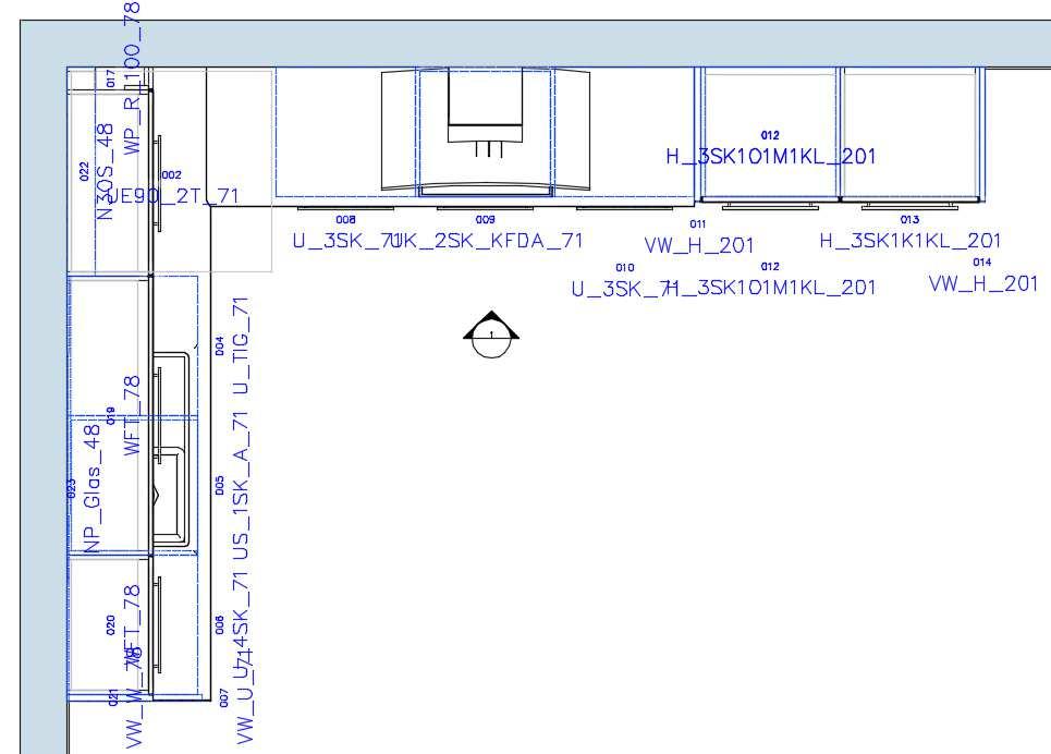
78 4.3 Example The annotation principle Plan_View was used for the following planning. It is defined in this principle that the DWG block Article_PosName should be used for the cabinets. The following attributes are defined in the Article_PosName.dwg: Workflow Example


79 The following information is then displayed for a tall cabinet in the annotation view: That corresponds to the details of the article for Position hierarchy and article name. You can also see that the font size is defined via the DWG too. Workflow Example
80 4.4 Creating annotation blocks (DWG) To create your own annotation blocks it is recommended that you open an existing annotation DWG in the directory <Library>\AttDWG, then save a copy of the file using the command Save as... That has the advantage that the data in this DWG has already been purged and does not contain any contents from the DWT template. In addition, the annotation blocks used to annotate plan views already have the property Annotation. (see following chapter) This property is retained when the file is saved using the command Save as.... The contents of the DWG can now be changed as desired. Possible usable imos attributes are described in the chapter 7.1 imos attributes. Workflow Creating annotation blocks (DWG)

81 4.4.1 Special characteristic It is possible to create blocks that are defined via the properties as Annotations. When annotating plan views, imos treats these in a special manner: Blocks created as Annotation are always orientated according to the coordinate system of the article. Tip To ensure that the text is never upside down, it is necessary that there is also a correspondingly mirrored DWG with the same designation but with the suffix _r added. For example, there is another DWG for Article_PosName.dwg with the name Article_PosName_r.dwg. This is used if the article in the plan view exceeds a certain degree of rotation. The next chapter contains a detailed description. Workflow Creating annotation blocks (DWG)

82 4.4.2 Creating blocks in imos OEM (AutoCAD OEM) Limitation / options Creating blocks for annotation purposes in imos OEM/AutoCAD OEM is limited: There is no command BLOCK, with which it is possible to define a block and, for example, allocate it the property annotation. There is no block editor [BBEARB], with which it is possible to create dynamic blocks or parametric blocks. In the OEM version there is merely the option of creating normal DWGs and then to use these as blocks. It is possible to: Use imos attribute definitions (for example, position numbers, names, etc.) Draw freehand (for example symbols) Fix texts etc. Workflow Creating annotation blocks (DWG)


83 Example You create a new drawing and enter the command IMOSATTDEF. Select the attribute you want from the list of imos attributes and click the green tick to insert it into the drawing. In Properties you can adapt the font size, style, color, etc., to meet your requirements. Workflow Creating annotation blocks (DWG)

84 Then save the file using the command SAVEAS. Note Select <Library>\AttDWG as the target path. It is now possible to use this DWG in the annotation principle. When used, the respective article name is displayed in the annotation. Note The DWG created here is not scaled automatically using the set scale. As mentioned previously, it is not possible to add the property annotation to a DWG in the OEM version. However, it is possible to use a DWG that already has the property annotation (for example, one included with the delivery data) as a template. All you need to do is open Workflow Creating annotation blocks (DWG)
85 the file in question and save it as a new file using the command Save as... Now it is possible to clear/delete the contents and define it from scratch. If you now save this DWG, it will still have the property annotation Creating blocks in imos CAD (AutoCAD full version) You basically create blocks in the AutoCAD full version in precisely the same way as in the OEM version (see above). However, the full AutoCAD version offers additional options: Using the command BLOCK it is possible to create blocks as annotation. That allows the blocks to be scaled automatically according to the set scale. It is possible to create dynamic blocks and parametric blocks with the aid of the AutoCAD block editor. Workflow Creating annotation blocks (DWG)
86 Creating scalable blocks The advantage of scalable blocks is that they react when the scale is altered and adapt accordingly. To create scalable blocks, proceed as follows: 1. Create a new drawing 2. Insert either an attribute with the command IMOSATTDEF 3. or simply just a drawing 4. If required, adapt the attribute properties (see also 7.3 Attributes to define detail blocks) 5. Call up the command BLOCK Workflow Creating annotation blocks (DWG)
 Select the check box Annotative d) Select the check box Open in block editor 7. Click OK to exit the dialog box.")
87 6. You must configure the following settings in the dialog box that opens: a) Name for the block b) Select objects (in the CAD) that are to be saved as blocks c) Select the check box Annotative d) Select the check box Open in block editor 7. Click OK to exit the dialog box. Workflow Creating annotation blocks (DWG)


88 8. If there is an attribute in the drawing, the Edit Attributes dialog box opens to facilitate editing the attributes. 9. Click OK to exit the dialog box; the Block editor then opens. Workflow Creating annotation blocks (DWG)
89 10. To save the block click the Open/save arrow on the far left of the ribbon menu. 11. Then select Save block as. Workflow Creating annotation blocks (DWG)

90 12. Enter a name for the block and select the check box Save block definition to drawing file in the dialog box that then opens. 13. Save the DWG in the directory AttDWG. 14. This block now has the property annotation and is scaled automatically when the scale is altered. Workflow Creating annotation blocks (DWG)
91 Creating dynamic blocks Note The AutoCAD block editor is required to create dynamic blocks or parametric blocks. This is only contained in the full version of AutoCAD. This feature is not available in the imos OEM version. The description below describes the structure and the creation of data of the existing Article_contour.dwg in the directory AttDWG. To create a dynamic block proceed as follows: 1. Create a new (empty) drawing. 2. Enter the AutoCAD command BEDIT to open the block editor. Workflow Creating annotation blocks (DWG)


92 3. Select <Current Drawing> 4. Click OK to exit the dialog box. 5. The ribbon menu Block editor opens. To configure a dynamic block, imos currently offers the following parameters for articles: ImosDepth ImosWidth ImosHeight Workflow Creating annotation blocks (DWG)


93 Using the parameters ImosDepth and ImosWidth it is possible to depict article contours for rectangular articles in plan views, for example. To do so, it suffices to draw a rectangle and to dimension it parametrically. The process continues as follows: 6. Draw a poly line so that you create a square measuring 100mmx100mm. 7. Fix the position of the vertical line in the zero point. To do so, call up the function Fixed in the ribbon menu. Workflow Creating annotation blocks (DWG)


94 8. Then pick the line. The line is then marked with a padlock. 9. Define constraints for all lines. To do so, call up the function Vertical in the ribbon menu of the block editor. 10. First pick the right vertical line and then, moving in a clockwise direction, the following top line. Continue in the same manner for the remaining lines. Workflow Creating annotation blocks (DWG)


95 11. Now open the Parameter Manager in the Block editor. 12. Now create a new user parameter. 13. Assign the desired imos parameter as the name. Workflow Creating annotation blocks (DWG)


96 14. Repeat the process and specify the Expression 500, so that the result, for example, looks as follows. 15. Dimension the square you drew. To do so, call up the function Horizontal in the ribbon menu. Workflow Creating annotation blocks (DWG)


97 16. Then first pick the left top corner point and then the right top corner point. 17. Move dimension line to the desired position. Workflow Creating annotation blocks (DWG)


98 18. The display switches over once you have defined the position so you are able to enter the value ImosWidth after the = character. 19. The width of the square changes automatically to the value 500 (=ImosWidth) after you click ENTER to confirm your setting. Workflow Creating annotation blocks (DWG)

99 20. Repeat the process for vertical dimensioning so that the following situation is created when you are finished. 21. As a consequence, the Parameter Manager now looks as follows: Workflow Creating annotation blocks (DWG)
100 22. To save the block click the Open/save arrow on the far left of the ribbon menu. 23. Then select Save block as. Workflow Creating annotation blocks (DWG)
101 24. Enter a name for the block and select the check box Save block definition to drawing file in the dialog box that then opens. 25. Save the DWG in the directory AttDWG. Workflow Creating annotation blocks (DWG)


102 Note When you use this block the definition of the insertion point or rather the reference point and the position setting are important. In this case it is recommended that you set the Insertion point top/left, because in imos this point is the standard insertion point for imos articles. That guarantees that the block is always suitably inserted in relation to the article. Workflow Creating annotation blocks (DWG)
103 5. Borders 5.1 Differences to SR1 Since ix 2017 version the drawing borders are saved in the database. Thus the border.dwg (<Library>\border\) used up to now is no longer necessary for using borders. Note The existing border.dwg is transferred to the database when you update your version; consequently, manual conversion is not necessary. Workflow Differences to SR1
 Load a drawing border If you wish to use a drawing border or modify a drawing border solely in the open order, select the drawing border you require and then click Apply")
104 5.2 Loading & editing drawing border To load a drawing border call up the function Load Border in the ribbon menu Output. That opens the Element Manager. Here you have two options: a) Load a drawing border If you wish to use a drawing border or modify a drawing border solely in the open order, select the drawing border you require and then click Apply to exit the dialog box. Edit a drawing border If you wish to make global changes to the drawing border, select the required drawing border and then click the Edit function symbol. Workflow Loading & editing drawing border
105 In case a) the drawing border is loaded it is inserted into the opened order as a new layout; its name is displayed below the graphic representation. If the drawing border is to be edited (case b), the drawing border is opened as a DWT and the file name is displayed with the prefix DmLayout_ in the tab at the top with an asterisk *. Note The function Save Border is only available if changes are made to the drawing border using the Edit function. If changes to the drawing border are saved directly in the order, it is not possible to save the changes globally. Workflow Loading & editing drawing border
106 5.3 Editing drawing border To edit an existing drawing border, first call up the function Load Border. Then select the required principle in the dialog box followed by the function Edit. That opens the selected border as DWT. Workflow Editing drawing border
107 5.3.1 Save border If you wish to save the changes under a different name, click with a right mouse click on the layout below the new name. Select the function Rename in the context menu and enter the new name in the blue highlighted field. Then click Save Border to save the drawing border. That creates a new drawing border with the new name. Workflow Editing drawing border

 To edit existing attributes, select Modify.")
108 5.3.2 Configure attributes To configure the attribute fields of the drawing border, click the Configure Attributes symbol in the ribbon menu. Select the output field with the mouse. The composition of the ribbon menu changes and the additional tab Configure Attributes is displayed. a) To edit existing attributes, select Modify. b) To add a new attribute to the attribute field, select Add. Workflow Editing drawing border
 Select Apply to apply the changes from the output field.")
109 Both functions open the dialogue imos Attribute. a) Select Apply to apply the changes from the output field. b) Select Cancel to leave the tab. Workflow Editing drawing border
.")

110 5.3.3 Save changes in drawing border a) If you have made changes to a drawing border loaded in an active order, in other words it is not loaded as a DWT, then save the changes in the order (Save). b) If you have opened the drawing border via Edit (as DWT) to make global changes, then save the changes via Save Border. That writes the changes to the database. Workflow Editing drawing border

111 5.4 Defining a viewport It is possible to set the following settings separately in the DWT of a drawing border for each viewport; they are important for outputs via the Document Manager: View direction Visual Styles Scale Label Tip Remember to save the changes in the DWT View direction To set the view direction in the viewport set the corresponding view via the ViewCube. Workflow Defining a viewport

112 5.4.2 Visual Styles To set the visual style, select the viewport and then set the desired visual style via the menu in the top row. Note In the OEM version it is possible to make this setting via the ribbon menu. Workflow Defining a viewport

113 5.4.3 Scale To set the scale, select the viewport and then define the scale via the AutoCAD toolbar. Note The scale set here will only be considered in the Document Manager output if fix scale is defined in the principle for the scale. For more information, see "6.3.3 Viewports". Workflow Defining a viewport
 Load the drawing border.")
114 5.4.4 Label viewport Note It is only necessary to label viewports to define the layout in Document Manager 2.0. If you wish to check if the viewports have already been labeled in the drawing border being used, proceed as follows: a) Load the drawing border. b) Call up the function Label viewport in the ribbon menu. If they have already been labeled, the respective name will be displayed in the viewports in red. Workflow Defining a viewport
115 Note If you do not label the viewports, they cannot be used later in the Document Manager. If you wish to rename the viewports of a drawing border, proceed as follows: c) Edit the drawing border (see chapter "1.3"). d) Call up the function Label viewport in the ribbon menu. e) Click <unnamed> with the mouse pointer in the appropriate viewport. Workflow Defining a viewport
116 f) Type in the label name and click ENTER to confirm your choice. g) If you wish to label more viewports, click the next viewport and proceed as above h) To abort the process, press ESC. i) Then click Save border to save the changes. j) Close the DWT. k) The viewport is now available to be selected in the Document Manager. Tip To check, simply call up the function Label viewport again. Workflow Defining a viewport
117 5.5 Creating new drawing borders If you wish to create a new drawing border by using an existing drawing border as a template, call up the function Load Border. Then select the required principle in the dialog box followed by the function Edit. That opens the selected border as DWT. Workflow Creating new drawing borders
118 The name of the layout / drawing border is displayed below. Right-click the desired layout and then select Rename. Type in the new name into the name box highlighted blue. Workflow Creating new drawing borders

119 Make the required modifications (see "1.3.2 Editing drawing borders") and select Save Border in the ribbon menu. Close the opened DWT without saving any further changes. If you now load the drawing borders again, the newly created drawing border is available for selection in the list. Workflow Creating new drawing borders

120 5.6 Creating and editing page setups Note The description below will be of most interest to customers who use the Document Manager, which contains output formats other than DWG. The page setup must be carried out for each drawing border separately. If you wish to use custom paper sizes, you can define these via the PC3 plotter driver. They are administrated in the Page Setup Manager. To call up the Page Setup Manager right-click the desired layout, then select Page Setup Manager in the shortcut menu. Workflow Creating and editing page setups
 and which paper size are to be used.")

121 The Page Setup Manager is an AutoCAD dialog box in which it is possible to create named page setups, edit page setups or import page set-ups from other drawings. In other words, it is possible to define which printer (e.g., PDF, PNG, JPG or a real printer) and which paper size are to be used. All page setups created for this drawing border are available in the list. These are so-called PC3 files (Plotter Configuration Files). Note These are saved solely as user-specific files; for example, they are not available for exporting. To create a new page setup, click New. To setup a new page, enter a name. Select a paper size to use as a template from the list. Then click OK to exit the dialog box. Workflow Creating and editing page setups


122 A new dialog box will open. Now select the desired output format or rather the printer/plotter for the name. Select the paper size in the same dialog. Workflow Creating and editing page setups

123 Then click OK. You have created a new page setup. Close the Page Setup dialog box, then save the drawing border. Workflow Creating and editing page setups
, then you have the option of creating custom")

124 5.7 Customer paper sizes If the paper size you require is not available in the picklist when configuring the page setup (or the right pixel resolution for PNG/JPG), then you have the option of creating custom paper sizes. To do so, click Properties in the Page Setup dialog box. The Plotter Configuration Editor opens. This is where you define the paper sizes. Select Custom Paper Sizes then click Add. Workflow Customer paper sizes


125 On the start page of the Custom Paper Size wizard select the On the Media bounds dialog box select the option Millimeters from the Units list. Note If you plot a non-dimensional raster image (for example, a BMP or TIFF file), then the size of the plot is specified in pixels not inches or millimeters. Enter the desired values in the Width and Height lists. Click Next. Workflow Customer paper sizes

126 Note The maximum printable area of a plotter is determined by the paper feed roller and how far the pen shuttle is able to reach. If you create a paper size that exceeds the paper sizes offered in the Custom Paper Size wizard, you will need to determine if it is within the maximum printable area of the plotter. Tip When defining the size in pixels, you must take into consideration that the number of pixels depends on the resolution being used. Pixels at 300 dpi Pixels at 150 dpi ISO DIN A x x 7022 ISO DIN A x x 4967 ISO DIN A x x 3508 ISO DIN A x x 2480 ISO DIN A x x 1754 Workflow Customer paper sizes


127 Enter a name for the paper size on the Paper Size Name page. Click Next. Specify on the Finish page if the paper source is sheet fed or roller fed. Click Finish to exit the Custom Paper Size wizard. Then you return back to the Plotter Configuration Editor. Select Save as. Workflow Customer paper sizes


128 The default path to the folder where configuration files are saved is displayed in the Save as dialog box. Enter a user-specific file name for the file. Click Save to exit the dialog box. Click OK to exit the Plotter Configuration Editor. The configuration file is now available for plotting. Workflow Customer paper sizes
129 6. Document Manager 2.0 It is possible to create automated drawing outputs with the aid of the Document Manager. In comparison with the previous version Document Manager 2.0 has been completely revised according to a new concept; it is now managed in the Element Manager. Note For existing installations For reasons of compatibility the new Document Manager is not activated automatically, but needs to be activated manually. Please contact imos Support if you have any questions. For new installations In case of a new imos installation the new Document Manager is enabled from the beginning. There are representative sample data in the delivery data that can be used. Workflow Customer paper sizes


130 6.1 Overview With the new Document Manager it is now possible to use and configure several viewports in a layout. Visual style, orientation and scale ratio are configured directly in the viewport of the layout. Layouts and viewports must be labeled first before they can be used in the Document Manager principle. Please read also Workflow Overview
131 Label viewport. Workflow Overview

132 The content and functions to be used are then set in the Document Manager principle. Another advantage of the Document Manager 2.0 is the option to output different file formats via the AutoCAD plotter driver. It is possible to configure these via individual page setups. For instance, it is possible to create formats such as PDF, PNG, JPG and so forth in various quality levels and resolutions. Workflow Overview
133 Key facts Integrated in Element Manager Several viewports possible in a single layout Several layouts configurable per principle User determines visual style, orientation and scale ratio User determines contents of viewports New part dimensioning and indexing functions integrated Plotter/printer driver supports other output formats (PDF, PNG, JPG, etc.) Output paths and file names configurable Workflow Overview


134 6.2 Call up and workflow The workflow required to call up the Document Manager has mostly remained the same. 1. Open the order for which the Document Manager process run is to be started, or rather save the order. 2. Start the Document Manager via the function Output format in the ribbon menu. 3. The Element Manager opens on the Document Manager Principle level. 4. Select the desired principle. Note The structure of the old Document Manager has been replicated for the Document Manager principles DM_Article_Preview and DM_PartDimensioning. If the Document Manager is to be issued via the reports, you must use the DM principle DM_PartDimensioning. Workflow Call up and workflow


135 5. Click on Apply. 6. Click and hold the mouse button, then drag the mouse pointer over the articles that are to be processed by the Document Manager. 7. Right-click the chosen articles and select Confirm in the shortcut menu. Workflow Call up and workflow


136 8. The Document Manager processes the selected articles when you confirm your action. The progress bar indicates how many drawings have been processed. You can carry on working in the CAD system as soon as the progress bar reaches 100 per cent. The other output formats, such as PDF, PNG, etc., are plotted in the background until complete. 9. By default, the created files are saved in the subfolder DOC of the order directory. However, it is also possible to define a user-specific file drop path. Read also File name Workflow Call up and workflow
137 Graphics of the article and dimensioned articles are generated as an example in the Document Manager process run depicted here. Note The process run depicted here was opened as a PDF file via the directory. Workflow Call up and workflow

138 The new part dimensioning with indexing functions is used for the parts. 10. To complement the Document Manager example, the delivery data contains an executable report created for this principle. Workflow Call up and workflow

139 The report puts the outputs in order so that the dimensioned article is displayed first followed by its parts. They are followed by the next article, which is in turn followed by its parts. Tip It is also possible to start the Document Manager process run via the Save as dialog box. To do so, you must select the required principle from the list of available principles. The Document Manager process run is started immediately when you click the green check mark to exit the dialog box. All of the articles contained in the order are then processed (there is no need to select them manually). Workflow Call up and workflow
. 6.3.")
140 6.3 Understanding how it works and settings A description of the individual settings and configuration options for the Document Manager is offered below. The availability of suitable drawing borders is a fundamental requirement (see 5.2 Loading & editing drawing border) Layouts The grid for the layouts or rather the drawing borders is located on the top level of the Document Manager principle. The picklist contains all previously created drawing borders. Please refer to 5.2 Loading & editing drawing border. It is possible to use several layouts for a principle. Click the small + symbol at the beginning of the row to access further settings options to configure output formats, viewports and file names. More information is provided in the next chapters. Workflow Understanding how it works and settings
141 6.3.2 Output formats It is possible to define the desired output formats for each layout. Select the check box Black-and-white to set all layer colors to black-and-white during the process run of the Document Manager. In other words, all layer colors are ignored when this function is active. Note When the check box Output DWG is cleared all DWGs are deleted after the selected output formats are generated and the Document Manager process run is finished. Workflow Understanding how it works and settings


142 It is possible to generate formats other than DWGs. The list of formats, the so-called page setups, depends on the layout and is individually configurable. For more information, see chapter 5.6 pp. If, for example, the principle JPG_1218x1576 was saved in the DWT of the drawing border DinA0_article via the Page Setup Manager, then this principle for the layout is available in the list of page setups Viewports It is possible to define the depicted contents for the individual viewports of each layout. Note To do so, the viewports must be labeled. Please read also 0 Workflow Understanding how it works and settings


143 Label viewport. The Name list consists of the labeled viewports that are available in the selected drawing border. Workflow Understanding how it works and settings
 Fix scale The AutoCAD scale of the viewport is used Best scale")

144 There are three options available when selecting the scale: Zoom extents This depicts all objects in a scene (zoom all) Fix scale The AutoCAD scale of the viewport is used Best scale The most suitable scale is chosen from the list of available scales. Note If zoom extents is selected, be aware that annotations are not scaled. Workflow Understanding how it works and settings

145 The Object level defines which object is to be processed in the viewport. Depending on this selection, different functions are made available. Tip If, for example, planposition is selected as the object level in the layout but the order does not contain a planposition, a message is displayed informing that it is not possible to generate an output for the selected objects. The Object sequence defines the order in which the objects are sorted When Same object is selected the same object is depicted in each viewport of a drawing border (e.g., an article) When Next object is selected the next object is depicted in each viewport of a drawing border (e.g., an article) Workflow Understanding how it works and settings


146 The Functions available depend on the selected Object level; they define further options regarding what is depicted in the viewports. Workflow Understanding how it works and settings


147 Depending on the chosen function there are different Attributes available for selection (see screenshots left). Workflow Understanding how it works and settings

148 6.3.4 Functions available depending on the object level Note View direction, visual style and scale are determined by the settings in the viewport of the drawing border being used. Object level - planposition Show object The complete planposition is depicted. However, it is a precondition that the order contains a planposition! Workflow Understanding how it works and settings

149 Object level - article Size dimensioning The outside dimensions of the article are dimensioned. Dimension frame face The face frame are dimensioned. A corresponding object filter has to be selected. Otherwise an error message is displayed! The dimensioning principles are the old dimensioning principles. Workflow Understanding how it works and settings

150 Part references All parts of the article are referenced. This function makes it possible to define an attribute block to be used for referencing via Attributes. Show object The complete article is depicted. Workflow Understanding how it works and settings

151 Object level - group Size dimensioning The outside dimensions of the individual imos groups are dimensioned. Workflow Understanding how it works and settings


152 Drawer dimensioning Drawer dimensioning makes it possible to define different dimensioning principles via the attributes for connectors and identifiers. Show object This makes it possible to define the explosion factor via Attributes. The drawing is depicted exploded when the explosion factor is set to 1. Workflow Understanding how it works and settings
153 Object level - part Part dimensioning (automatic) With this function it is possible to define via Attributes if an indexing table is to be inserted or not. Indexing was used in the graphic depicted opposite! When selecting this function, you should always use a viewport that uses top view! Part referencing in the article Depicts the position of the part in the article. Workflow Understanding how it works and settings

154 6.3.5 File name It is possible to determine a user-specific file drop path when defining the file name. Note If no details are defined, the generated files are saved to the subfolder DOC of the order directory! An example is used below to explain the possible definitions: Order name: WhatsNew_04 Article name: U_1T1SK_71 fixed text \..\ A subdirectory is created in the order directory Then the definition is configured Complete length of the feature Article ID The name of the subdirectory begins with the article ID. In this example fixed text_ An underscore (_) is used for the name following the article ID. Complete length of the feature construction principle The article name is used fixed text \ Ends the definition of the directory name fixed text PERSP Name of the files - in this case: PERSP Workflow Understanding how it works and settings
155 6.4 Best practice Output format for tall cabinets The task is to create a drawing output for tall cabinets. The result should look as follows: Workflow Best practice
156 To achieve this, you must first define the drawing border. This requires: Drawing border in DIN A3 format 6 viewports with different attributes The six viewports must be labeled! The following attributes must be defined for the individual viewports: Top view View from top Display as 2D Wireframe Definition of a fixed scale of 1:16 Workflow Best practice

157 Left Left View Display as 2D Wireframe Definition of a fixed scale of 1:16 Front Front View Display as 2D Wireframe Definition of a fixed scale of 1:16 Right Right View Display as 2D Wireframe Definition of a fixed scale of 1:16 Workflow Best practice

158 Explosion Isometric view southeast Display grey shaded Article Isometric view southeast Display grey shaded To ensure that only tall cabinets are depicted in the drawing border, you must first define the following condition via the Element Manager: In this case, a tall cabinet is easily defined via the height setting: greater than or equal to 1000 mm. Workflow Best practice

159 Note The width of the article is not taken into consideration. The following attributes must now be defined in the Document Manager principle: Assign the created drawing border via the Layout name. Workflow Best practice
: The created condition must be")

160 As a first step, the following definition must be made for the viewports (see screenshot opposite): The created condition must be assigned to all viewports. This ensures only tall cabinets are depicted; in other words, articles with a height > 1000 mm. Workflow Best practice


161 An explosion factor 1 must be defined for the viewport Explosion. The representation and degree of detail are determined via the Visualization Level. Workflow Best practice

162 6.4.2 Adapt fuzzy images via reports of PC3 files - suitable paper size PNG format is defined for the output. When the drawing is opened it is obvious that the title block is fuzzy. The reason is that an unsuitable page setup has been selected/exists. In this example, a PNG format was used with a pixel resolution of 1576 x However, it is recommended that you use a pixel resolution of 2480 x 3508 for an output of 300 dpi for DIN A4. Pixels at 300 dpi Pixels at 150 dpi ISO DIN A x x 7022 ISO DIN A x x 4967 ISO DIN A x x 3508 ISO DIN A x x 2480 ISO DIN A x x 1754 Workflow Best practice

163 6.4.3 Message informing it is not necessary to produce a drawing for the selected objects If the message opposite is displayed at the beginning of a Document Manager process run, a possible reason could be that an element was defined in the Document Manager principle for the output format that does not exist in the order, for example, a planposition. Workflow Best practice
164 7. Additional information 7.1 imos attributes The field definitions are required to annotate plan views, views and sections. A list containing all of the field definitions is available in the imos Online Help under Attribute names. 7.2 Information text formats Information text formats are relevant for the indexing function of part dimensioning (imosdimindex.dwg) Defaults The following definitions are entered in the imosdimindex.dwg for the different types: Drilling: Drilling Dia={D}mm, {T{Depth=} {Through}} {R{ } {Bottom}} Lineboring: Lineboring R={LR}, Dia={D}, {T{Depth=} {Through}} {R{ } {Bottom}} Number:{LN} Workflow imos attributes
165 Groove: Groove width={b}, {T{Depth=} {Through}} {R{ } {Bottom}} Inner Contour: Inner Contour h={t}, {NAME} Circular Pocket: Circular Pocket Depth={T} Rectangular Pocket /Macro: Rectangular Pocket Depth={T}, R={ER} Edge: Profile Name={NAME},Thickness={D} Note Ford data in inches, the unit has to be defined as /in. Mm are used as default. Example: Hole = "Hole Ø={D/in}, {{T=} {through}} {R{ } {bottom}/in}" Workflow Information text formats


166 Example If you open the imosdimindex.dwg and take a look at the properties of the attribute Groove, you will see the following definition below Text/prompt: In the output that means the following information is issued about a groove: Workflow Information text formats
imos Getting Started
 imos 12.0 - Getting Started June 2015 imos Aktiengesellschaft Planckstraße 24 D-32052 Herford Tel. +49(0)5221.976-0 Fax +49(0)5221.976-123 info@imos3d.com www.imos3d.com This document is provided just
1: INTRODUCTION TO AUTOCAD
 AutoCAD syllabus 1: INTRODUCTION TO AUTOCAD Starting AutoCAD AutoCAD Screen Components Drawing Area Command Window Navigation bar Status bar Invoking Commands in AutoCAD Keyboard Ribbon Application Menu
Drawing Layouts Paper space & Model Space
 Drawing Layouts Paper space & Model Space Users of Bricscad will have seen the tabs at the bottom left of the drawings area labelled: Model, Layout1, Layout2 but may not know how to use them or what they
AutoCAD Tutorial First Level. 2D Fundamentals. Randy H. Shih SDC. Better Textbooks. Lower Prices.
 AutoCAD 2018 Tutorial First Level 2D Fundamentals Randy H. Shih SDC PUBLICATIONS Better Textbooks. Lower Prices. www.sdcpublications.com Powered by TCPDF (www.tcpdf.org) Visit the following websites to
Autodesk Advance Steel. Drawing Style Manager s guide
 Autodesk Advance Steel Drawing Style Manager s guide TABLE OF CONTENTS Chapter 1 Introduction... 5 Details and Detail Views... 6 Drawing Styles... 6 Drawing Style Manager... 8 Accessing the Drawing Style
Training CAD/ Part Designer: Designing with Angled Parts
 Training CAD/ Part Designer: Designing with Angled Parts We have attempted to keep the content of this document complete, accurate and under permanent review. However, due to the continuous development,
Advance Steel. Drawing Style Manager s guide
 Advance Steel Drawing Style Manager s guide TABLE OF CONTENTS Chapter 1 Introduction...7 Details and Detail Views...8 Drawing Styles...8 Drawing Style Manager...9 Accessing the Drawing Style Manager...9
Chapter 6 Title Blocks
 Chapter 6 Title Blocks In previous exercises, every drawing started by creating a number of layers. This is time consuming and unnecessary. In this exercise, we will start a drawing by defining layers
AutoCAD LT 2012 Tutorial. Randy H. Shih Oregon Institute of Technology SDC PUBLICATIONS. Schroff Development Corporation
 AutoCAD LT 2012 Tutorial Randy H. Shih Oregon Institute of Technology SDC PUBLICATIONS www.sdcpublications.com Schroff Development Corporation AutoCAD LT 2012 Tutorial 1-1 Lesson 1 Geometric Construction
Introduction to Autodesk Inventor for F1 in Schools (Australian Version)
") Introduction to Autodesk Inventor for F1 in Schools (Australian Version) F1 in Schools race car In this course you will be introduced to Autodesk Inventor, which is the centerpiece of Autodesk s Digital
Introduction to Autodesk Inventor for F1 in Schools (Australian Version) F1 in Schools race car In this course you will be introduced to Autodesk Inventor, which is the centerpiece of Autodesk s Digital
Create all plan and profile sheets in the current drawing. Create all plan and profile sheets in individual drawings.
 NOTES Module 18 Roadway Plan Production In this module, you learn how to work with Roadway Plan Production tools in AutoCAD Civil 3D. The Plan Production tools are used to automate the generation of plan
Lesson 6 2D Sketch Panel Tools
 Lesson 6 2D Sketch Panel Tools Inventor s Sketch Tool Bar contains tools for creating the basic geometry to create features and parts. On the surface, the Geometry tools look fairly standard: line, circle,
Revit Structure 2012 Basics:
 SUPPLEMENTAL FILES ON CD Revit Structure 2012 Basics: Framing and Documentation Elise Moss autodesk authorized publisher SDC PUBLICATIONS www.sdcpublications.com Schroff Development Corporation Structural
06/17/02 Page 1 of 12
 Understanding the Graphical User Interface When you start AutoCAD, the AutoCAD window opens. The window is your design work space. It contains elements that you use to create your designs and to receive
Getting Started Guide
 SOLIDWORKS Getting Started Guide SOLIDWORKS Electrical FIRST Robotics Edition Alexander Ouellet 1/2/2015 Table of Contents INTRODUCTION... 1 What is SOLIDWORKS Electrical?... Error! Bookmark not defined.
Revit Structure 2013 Basics
 Revit Structure 2013 Basics Framing and Documentation Elise Moss Supplemental Files SDC P U B L I C AT I O N S Schroff Development Corporation Better Textbooks. Lower Prices. www.sdcpublications.com Tutorial
Existing and Design Profiles
 NOTES Module 09 Existing and Design Profiles In this module, you learn how to work with profiles in AutoCAD Civil 3D. You create and modify profiles and profile views, edit profile geometry, and use styles
An Introduction to Dimensioning Dimension Elements-
 An Introduction to Dimensioning A precise drawing plotted to scale often does not convey enough information for builders to construct your design. Usually you add annotation showing object measurements
with MultiMedia CD Randy H. Shih Jack Zecher SDC PUBLICATIONS Schroff Development Corporation
 with MultiMedia CD Randy H. Shih Jack Zecher SDC PUBLICATIONS Schroff Development Corporation WWW.SCHROFF.COM Lesson 1 Geometric Construction Basics AutoCAD LT 2002 Tutorial 1-1 1-2 AutoCAD LT 2002 Tutorial
Principles and Applications of Microfluidic Devices AutoCAD Design Lab - COMSOL import ready
 Principles and Applications of Microfluidic Devices AutoCAD Design Lab - COMSOL import ready Part I. Introduction AutoCAD is a computer drawing package that can allow you to define physical structures
Revit Structure 2014 Basics
 Revit Structure 2014 Basics Framing and Documentation Elise Moss Authorized Author SDC P U B L I C AT I O N S Better Textbooks. Lower Prices. www.sdcpublications.com Powered by TCPDF (www.tcpdf.org) Visit
[EC202 AutoCAD Topic Dimension] DEC 2010
![[EC202 AutoCAD Topic Dimension] DEC 2010](/thumbs/75/71849153.jpg "[EC202 AutoCAD Topic Dimension] DEC 2010") DIMENSIONING OBJECTIVES At the end of the unit you will be able to: Create linear dimensions with DIMLINEAR, DIMCONTINUE, DIMBASELINE, DIMALIGNED. Create radial dimensions with DIMDIAMETER and DIMRADIUS.
DIMENSIONING OBJECTIVES At the end of the unit you will be able to: Create linear dimensions with DIMLINEAR, DIMCONTINUE, DIMBASELINE, DIMALIGNED. Create radial dimensions with DIMDIAMETER and DIMRADIUS.
Assignment 13 CAD Mechanical Part 2
 Assignment 13 CAD Mechanical Part 2 Objectives In this assignment you will learn to apply the hatch and break commands along with commands previously learned. General Instructions Hatching 1. When AutoCAD's
SDC. AutoCAD LT 2007 Tutorial. Randy H. Shih. Schroff Development Corporation Oregon Institute of Technology
 AutoCAD LT 2007 Tutorial Randy H. Shih Oregon Institute of Technology SDC PUBLICATIONS Schroff Development Corporation www.schroff.com www.schroff-europe.com AutoCAD LT 2007 Tutorial 1-1 Lesson 1 Geometric
Geometry Controls and Report
 Geometry Controls and Report 2014 InnovMetric Software Inc. All rights reserved. Reproduction in part or in whole in any way without permission from InnovMetric Software is strictly prohibited except for
Dimensioning the Rectangular Problem
 C h a p t e r 3 Dimensioning the Rectangular Problem In this chapter, you will learn the following to World Class standards: 1. Creating new layers in an AutoCAD drawing 2. Placing Centerlines on the drawing
Assignment 5 CAD Mechanical Part 1
 Assignment 5 CAD Mechanical Part 1 Objectives In this assignment you will apply polyline, offset, copy, move, and rotated dimension commands, as well as skills learned in earlier assignments. Getting Started
Tutorial 2: Setting up the Drawing Environment
 Drawing size With AutoCAD all drawings are done to FULL SCALE. The drawing limits will depend on the size of the items being drawn. For example if our drawing is the plan of a floor 23.8m X 15m then we
Advance Concrete. Tutorial
 Advance Concrete Tutorial Table of contents About this tutorial... 9 How to use this guide... 10 Lesson 1: Creating a building grid... 11 Step 1: Create a default building grid... 11 Step 2: Set the distances
Chapter 2. Drawing Sketches for Solid Models. Learning Objectives
 Chapter 2 Drawing Sketches for Solid Models Learning Objectives After completing this chapter, you will be able to: Start a new template file to draw sketches. Set up the sketching environment. Use various
AutoCAD LT 2009 Tutorial
 AutoCAD LT 2009 Tutorial Randy H. Shih Oregon Institute of Technology SDC PUBLICATIONS Schroff Development Corporation www.schroff.com Better Textbooks. Lower Prices. AutoCAD LT 2009 Tutorial 1-1 Lesson
Section 1. Introduction and Review. Objectives: Log on to the computer Launch AutoCAD Create, open, and save a drawing Review AutoCAD basics
 Section 1 Introduction and Review Objectives: Log on to the computer Launch AutoCAD Create, open, and save a drawing Review AutoCAD basics Drawing Assignments: NCAA Basketball Court Plot Style Table (Check-off)
NEORSD. Cad Standards and Procedures Manual
 NEORSD Cad Standards and Procedures Manual This Manual is being provided to you on loan from the NEOSRD and is the property of the NEOSRD. Periodic updates will be provided and you are responsible for
Making an Architectural Drawing Template
 C h a p t e r 8 Addendum: Architectural Making an Architectural Drawing Template In this chapter, you will learn the following to World Class standards:! Starting from Scratch for the Last time! Creating
Advance Steel. Tutorial
 Advance Steel Tutorial Table of contents About this tutorial... 7 How to use this guide...9 Lesson 1: Creating a building grid...10 Step 1: Creating an axis group in the X direction...10 Step 2: Creating
User s Manual ❿ Drawings-Detailing
 User s Manual ❿ Drawings-Detailing 2 CONTENTS I. THE NEW UPGRADED INTERFACE of SCADA Pro 4 1. UNITS 5 1.1 Drawings-Detailing 5 I. Files 6 II. Drawing 25 III. Formworks 30 IV. Edit 45 V. View 58 VI. Layers
Architecture 2012 Fundamentals
 Autodesk Revit Architecture 2012 Fundamentals Supplemental Files SDC PUBLICATIONS Schroff Development Corporation Better Textbooks. Lower Prices. www.sdcpublications.com Tutorial files on enclosed CD Visit
GstarCAD Mechanical 2015 Help
 1 Chapter 1 GstarCAD Mechanical 2015 Introduction Abstract GstarCAD Mechanical 2015 drafting/design software, covers all fields of mechanical design. It supplies the latest standard parts library, symbols
7.0 - MAKING A PEN FIXTURE FOR ENGRAVING PENS
 7.0 - MAKING A PEN FIXTURE FOR ENGRAVING PENS Material required: Acrylic, 9 by 9 by ¼ Difficulty Level: Advanced Engraving wood (or painted metal) pens is a task particularly well suited for laser engraving.
Assignment 6 CAD Mechanical Part 1 Editing Tools Objectives
 Assignment 6 CAD Mechanical Part 1 Editing Tools Objectives In this assignment you will apply the explode and rectangular array commands, as well as skills learned in earlier assignments. Getting Started
Getting Started. with Easy Blue Print
 Getting Started with Easy Blue Print User Interface Overview Easy Blue Print is a simple drawing program that will allow you to create professional-looking 2D floor plan drawings. This guide covers the
Advanced Topics Using the Sheet Set Manager in AutoCAD
 Advanced Topics Using the Sheet Set Manager in AutoCAD Sam Lucido Haley and Aldrich, Inc. GEN15297 Do you still open drawings one at a time? Do you print drawings one at a time? Do you update the index
Release Notes - Fixes in Tekla Structures 2016i PR1
 Release Notes - Fixes in Tekla Structures 2016i PR1, you can now set the to either or. is modified., the ID of the connection plate is not changed anymore when the connection now uses normal rebar groups
Making a Drawing Template
 C h a p t e r 8 Addendum: Metric Making a Drawing Template In this chapter, you will learn the following to World Class standards: 1. Starting from Scratch 2. Creating New Layers in an progecad Drawing
COURSE UNIT 3. Plan Creation. Messerli EliteCAD Version
 Messerli EliteCAD Version 13 27.09.2013 COURSE UNIT 3 Plan Creation Switzerland: Austria: Germany: Messerli Informatik AG Messerli Informatik GmbH Messerli Informatik GmbH Pfadackerstrasse 6 Hamoderstraße
AutoCAD Civil 3D 2009 ESSENTIALS
 AutoCAD Civil 3D 2009 ESSENTIALS SDC PUBLICATIONS Schroff Development Corporation www.schroff.com Better Textbooks. Lower Prices. Alignments and Profiles Section 2: Profiles In this section you learn how
CBCL Limited Sheet Set Manager Tutorial 2013 REV. 02. CBCL Design Management & Best CAD Practices. Our Vision
 CBCL Limited Sheet Set Manager Tutorial CBCL Design Management & Best CAD Practices 2013 REV. 02 Our Vision To be the most respected and successful Atlantic Canada based employeeowned firm, delivering
Appendix B: Autocad Booklet YR 9 REFERENCE BOOKLET ORTHOGRAPHIC PROJECTION
 Appendix B: Autocad Booklet YR 9 REFERENCE BOOKLET ORTHOGRAPHIC PROJECTION To load Autocad: AUTOCAD 2000 S DRAWING SCREEN Click the start button Click on Programs Click on technology Click Autocad 2000
User Guide V10 SP1 Addendum
 Alibre Design User Guide V10 SP1 Addendum Copyrights Information in this document is subject to change without notice. The software described in this document is furnished under a license agreement or
ARCHICAD Introduction Tutorial
 Starting a New Project ARCHICAD Introduction Tutorial 1. Double-click the Archicad Icon from the desktop 2. Click on the Grey Warning/Information box when it appears on the screen. 3. Click on the Create
Template Drawings. Template Drawings. AutoCAD Essentials
 AutoCAD Essentials Starting a new drawing using any CAD software requires a series of steps. Measurement units, sheet size, layer designations, text fonts and text sizes plus many more items must be set.
Table of Contents. Lesson 1 Getting Started
 NX Lesson 1 Getting Started Pre-reqs/Technical Skills Basic computer use Expectations Read lesson material Implement steps in software while reading through lesson material Complete quiz on Blackboard
Modeling Basic Mechanical Components #1 Tie-Wrap Clip
 Modeling Basic Mechanical Components #1 Tie-Wrap Clip This tutorial is about modeling simple and basic mechanical components with 3D Mechanical CAD programs, specifically one called Alibre Xpress, a freely
Learning Guide. ASR Automated Systems Research Inc. # Douglas Crescent, Langley, BC. V3A 4B6. Fax:
 Learning Guide ASR Automated Systems Research Inc. #1 20461 Douglas Crescent, Langley, BC. V3A 4B6 Toll free: 1-800-818-2051 e-mail: support@asrsoft.com Fax: 604-539-1334 www.asrsoft.com Copyright 1991-2013
Working With Drawing Views-I
 Chapter 12 Working With Drawing Views-I Learning Objectives After completing this chapter you will be able to: Generate standard three views. Generate Named Views. Generate Relative Views. Generate Predefined
AutoCAD 2018 Fundamentals
 Autodesk AutoCAD 2018 Fundamentals Elise Moss SDC PUBLICATIONS Better Textbooks. Lower Prices. www.sdcpublications.com Powered by TCPDF (www.tcpdf.org) Visit the following websites to learn more about
House Design Tutorial
 House Design Tutorial This House Design Tutorial shows you how to get started on a design project. The tutorials that follow continue with the same plan. When you are finished, you will have created a
AutoCAD 2020 Fundamentals
 Autodesk AutoCAD 2020 Fundamentals ELISE MOSS Autodesk Certified Instructor SDC PUBLICATIONS Better Textbooks. Lower Prices. www.sdcpublications.com Powered by TCPDF (www.tcpdf.org) Visit the following
CAD Orientation (Mechanical and Architectural CAD)
") Design and Drafting Description This is an introductory computer aided design (CAD) activity designed to give students the foundational skills required to complete future lessons. Students will learn all
Design and Drafting Description This is an introductory computer aided design (CAD) activity designed to give students the foundational skills required to complete future lessons. Students will learn all
for Solidworks TRAINING GUIDE LESSON-9-CAD
 for Solidworks TRAINING GUIDE LESSON-9-CAD Mastercam for SolidWorks Training Guide Objectives You will create the geometry for SolidWorks-Lesson-9 using SolidWorks 3D CAD software. You will be working
An Introduction to Autodesk Inventor 2011 and AutoCAD Randy H. Shih SDC PUBLICATIONS. Schroff Development Corporation
 An Introduction to Autodesk Inventor 2011 and AutoCAD 2011 Randy H. Shih SDC PUBLICATIONS www.sdcpublications.com Schroff Development Corporation An Introduction to Autodesk Inventor 2011 and AutoCAD 2011
Getting Started with. Vectorworks Architect
 Getting Started with Vectorworks Architect Table of Contents Introduction...2 Section 1: Program Installation and Setup...6 Installing the Vectorworks Architect Program...6 Exercise 1: Launching the Program
Exercise 1: The AutoCAD Civil 3D Environment
 Exercise 1: The AutoCAD Civil 3D Environment AutoCAD Civil 3D Interface Object Base Layer Object Component Layers 1-1 Introduction to Commercial Site Grading Plans AutoCAD Civil 3D Interface AutoCAD Civil
Making Standard Note Blocks and Placing the Bracket in a Drawing Border
 C h a p t e r 12 Making Standard Note Blocks and Placing the Bracket in a Drawing Border In this chapter, you will learn the following to World Class standards: Making standard mechanical notes Using the
DRAFT Solid Edge ST4 Update Training Draft
 DRAFT Solid Edge ST4 Update Training Draft Presented by: Steve Webb Topics Parts List Table Titles Column Headers Headers Merging Header Rotate Cell Aspect Ratio Cell Formatting Overriding Disabled Cells
SMALL OFFICE TUTORIAL
 SMALL OFFICE TUTORIAL in this lesson you will get a down and dirty overview of the functionality of Revit Architecture. The very basics of creating walls, doors, windows, roofs, annotations and dimensioning.
TABLE OF CONTENTS INTRODUCTION...4
 Starting Guide TABLE OF CONTENTS INTRODUCTION...4 Advance Steel... 4 Where to find information?... 5 INSTALLATION... 5 System requirements... 5 Starting the installation... 5 STARTING ADVANCE STEEL...
COMPUTER AIDED DRAFTING LAB (333) SMESTER 4
 SMESTER 4") COMPUTER AIDED DRAFTING LAB (333) SMESTER 4 Introduction to Computer Aided Drafting: The method of preparing engineering drawing by using the computer software is known as Computer Aided Drafting (CAD).
COMPUTER AIDED DRAFTING LAB (333) SMESTER 4 Introduction to Computer Aided Drafting: The method of preparing engineering drawing by using the computer software is known as Computer Aided Drafting (CAD).
Autodesk AutoCAD 2013 Fundamentals
 Autodesk AutoCAD 2013 Fundamentals Elise Moss SDC P U B L I C AT I O N S Schroff Development Corporation Better Textbooks. Lower Prices. www.sdcpublications.com Visit the following websites to learn more
Dimension Styles. EDT Chapter 18 - Basic Dimensioning Practices 1
 Dimension Styles EDT 310 - Chapter 18 - Basic Dimensioning Practices 1 Dimension Styles The appearance of dimensions is controlled by over 70 different settings. Dimension Styles are saved configurations
Release Notes - Fixes in Tekla Structures 2016i SP1
 Release Notes - Fixes in Tekla Structures 2016i SP1 is modified., the ID of the connection plate is not changed anymore when the connection now uses normal rebar groups instead of tapered groups., the
ACAD-BAU TUTORIAL For BricsCAD platform
 ACAD-BAU TUTORIAL WWW.ARHINOVA.SI For BricsCAD platform August 06 WORKSPACE ACAD-BAU RIBBON ACAD-BAU CONTROL BAR F ACAD-BAU PALETTES BASIC SETTINGS Use New command and open the template called ACB_International.DWT.
All About Object Designer
 All About Object Designer Documentation and manual of the imos Object Designer on the basis of the construction example "Sales counter" Juli 2010 Object Designer 24.09.12 1 / 47 Inhalt 1. General functions...
Sheet Metal OverviewChapter1:
 Sheet Metal OverviewChapter1: Chapter 1 This chapter describes the terminology, design methods, and fundamental tools used in the design of sheet metal parts. Building upon these foundational elements
Toothbrush Holder. A drawing of the sheet metal part will also be created.
 Prerequisite Knowledge Previous knowledge of the following commands is required to complete this lesson; Sketch (Line, Centerline, Circle, Add Relations, Smart Dimension,), Extrude Boss/Base, and Edit
A Quick Spin on Autodesk Revit Building
 11/28/2005-3:00 pm - 4:30 pm Room:Americas Seminar [Lab] (Dolphin) Walt Disney World Swan and Dolphin Resort Orlando, Florida A Quick Spin on Autodesk Revit Building Amy Fietkau - Autodesk and John Jansen;
GEO/EVS 425/525 Unit 2 Composing a Map in Final Form
 GEO/EVS 425/525 Unit 2 Composing a Map in Final Form The Map Composer is the main mechanism by which the final drafts of images are sent to the printer. Its use requires that images be readable within
Sheets Happen! Using the Sheet Set Manager
 Sheets Happen! Using the Sheet Set Manager Westwood Professional Services June 2007 Using AutoCAD s Sheet Set Manager Introduction The Sheet Set Manager organizes, displays, and manages sheet sets, a named
Siemens NX11 tutorials. The angled part
 Siemens NX11 tutorials The angled part Adaptation to NX 11 from notes from a seminar Drive-to-trial organized by IBM and GDTech. This tutorial will help you design the mechanical presented in the figure
State of Florida Department of Transportation. FDOT Traffic Plans. Signing & Pavement Markings (CE ) Signalization (CE ) Lighting
 Signalization (CE ) Lighting") State of Florida Department of Transportation FDOT Traffic Plans Signing & Pavement Markings (CE-11-0117) Signalization (CE-11-0119) Lighting (CE-11-0118) User Training Manual October 2017 PRODUCTION SUPPORT
State of Florida Department of Transportation FDOT Traffic Plans Signing & Pavement Markings (CE-11-0117) Signalization (CE-11-0119) Lighting (CE-11-0118) User Training Manual October 2017 PRODUCTION SUPPORT
ENGINEERING CO., LTD.
 Software RIP RasterLinkPro5 IP Reference Guide For UJF Series For JF Series For JFX Series This guide explains about features of RasterLinkPro5 IP for the UV Inkjet printer UJF Series, JF Series and JFX
Optimizing Digital Drawing Files and BIM Models for Measurement and Estimating
 Optimizing Digital Drawing Files and BIM Models for Measurement and Estimating Simon Lovegrove MRICS, AAIQS - Exactal CM4228 Drawing file formats issued for measurement and estimating purposes range from
Using Dynamic Views. Module Overview. Module Prerequisites. Module Objectives
 Using Dynamic Views Module Overview The term dynamic views refers to a method of composing drawings that is a new approach to managing projects. Dynamic views can help you to: automate sheet creation;
Drawing 8e CAD#11: View Tutorial 8e: Circles, Arcs, Ellipses, Rotate, Explode, & More Dimensions Objective: Design a wing of the Guggenheim Museum.
 Page 1 of 6 Introduction The drawing used for this tutorial comes from Clark R. and M.Pause, "Precedents in Architecture", VNR 1985, page 135. Stephen Peter of the University of South Wales developed the
Virtual components in assemblies
 Virtual components in assemblies Publication Number spse01690 Virtual components in assemblies Publication Number spse01690 Proprietary and restricted rights notice This software and related documentation
Unit. Drawing Accurately OVERVIEW OBJECTIVES INTRODUCTION 8-1
 8-1 Unit 8 Drawing Accurately OVERVIEW When you attempt to pick points on the screen, you may have difficulty locating an exact position without some type of help. Typing the point coordinates is one method.
ARC By default AutoCAD will draw an ARC through three selected points. Options can be set at the start and within the command.
 DFTG 1309 Final Review Notes I. Draw commands: LINE (draws a series of lines) Valid input: Pick button Cartesian coordinates Absolute (2,3) Relative rectangular (@2,3) Relative polar (@ 2
Create styles that control the display of Civil 3D objects. Copy styles from one drawing to another drawing.
 NOTES Module 03 Settings and Styles In this module, you learn about the various settings and styles that are used in AutoCAD Civil 3D. A strong understanding of these basics leads to more efficient use
CONTENT INTRODUCTION BASIC CONCEPTS Creating an element of a black-and white line drawing DRAWING STROKES...
 USER MANUAL CONTENT INTRODUCTION... 3 1 BASIC CONCEPTS... 3 2 QUICK START... 7 2.1 Creating an element of a black-and white line drawing... 7 3 DRAWING STROKES... 15 3.1 Creating a group of strokes...
Customized Foam for Tools
 Table of contents Make sure that you have the latest version before using this document. o o o o o o o Overview of services offered and steps to follow (p.3) 1. Service : Cutting of foam for tools 2. Service
Tools for Design. with VEX Robot Kit: Randy H. Shih Oregon Institute of Technology SDC PUBLICATIONS
 Tools for Design with VEX Robot Kit: AutoCAD 2011 and Autodesk Inventor 2011 2D Drawing 3D Modeling Hand Sketching Randy H. Shih Oregon Institute of Technology INSIDE: SUPPLEMENTAL FILES ON CD SDC PUBLICATIONS
Photoshop CS2. Step by Step Instructions Using Layers. Adobe. About Layers:
 About Layers: Layers allow you to work on one element of an image without disturbing the others. Think of layers as sheets of acetate stacked one on top of the other. You can see through transparent areas
Mastering AutoCAD 2D
 Course description: Mastering AutoCAD 2D Design and shape the world around you with the powerful, flexible features found in AutoCAD software, one of the world s leading 2D design applications. With robust
Version 9 Tutorial and User Guide
 Version 9 Tutorial and User Guide 800-989-4243 214-340-9436 support@vertigraph.com www.vertigraph.com 1 Table of Contents A. Overview... 4 B. About the SiteWorx/OS Window... 4 C. File Types Raster, Vector
House Design Tutorial
 Chapter 2: House Design Tutorial This House Design Tutorial shows you how to get started on a design project. The tutorials that follow continue with the same plan. When we are finished, we will have created
Introduction to AutoCAD 2012
 Page 1 Introduction to AutoCAD 2012 Alf Yarwood Answers to Multiple choice questions Chapter 1 1. The toolbar at the top of the AutoCAD 2012 window is: (a) The Draw toolbar (b) The Modify toolbar (c) The
Apex v5 Assessor Introductory Tutorial
 Apex v5 Assessor Introductory Tutorial Apex v5 Assessor Apex v5 Assessor includes some minor User Interface updates from the v4 program but attempts have been made to simplify the UI for streamlined work
Version 8 Tutorial
 Version 8 Tutorial 800-989-4243 214-340-9436 support@vertigraph.com www.vertigraph.com 1 Table of Contents A. Overview... 4 B. About the SiteWorx/OS Window... 4 C. File Types Raster, Vector and PDF...
Evaluation Chapter by CADArtifex
 The premium provider of learning products and solutions www.cadartifex.com EVALUATION CHAPTER 2 Drawing Sketches with SOLIDWORKS In this chapter: Invoking the Part Modeling Environment Invoking the Sketching
Assignment 12 CAD Mechanical Part 2
 Assignment 12 CAD Mechanical Part 2 Objectives In this assignment you will learn to apply the hidden lines, isometric snap, and ellipses commands along with commands previously learned.. General Hidden